Article

Assembly Deviation Analysis of New Integrated TBM Disc Cutter and Design of the Supporting Cutter-Changing Robot End-Effector

School of Mechanical Engineering, Dalian University of Technology, Dalian 116024, China
*
Author to whom correspondence should be addressed.
Appl. Sci. 2022, 12(19), 9549; https://doi.org/10.3390/app12199549
Submission received: 16 August 2022 / Revised: 15 September 2022 / Accepted: 16 September 2022 / Published: 23 September 2022

Abstract

:
At present, the replacement of disc cutters of the tunnel boring machine (TBM) is a very important and difficult manual operation. It is meaningful to study disc cutters of TBM replacement with a robot. In this paper, the machining and assembly deviation of the new integrated disc cutter developed by our research group is modeled and analyzed using the improved Jacobian–Torsor model, and the analysis results are verified by experiments. On this basis, aiming at the possible radial deviation and angle deviation in the working process of a robot replacing TBM disc cutters, a cutter-changing robot end-effector composed of a guiding mechanism, a flexible connecting mechanism and a universal wrench is designed for the disassembly and assembly of the new integrated disc cutter, and scaled-down models were made for the experiment. The test results show that when there is a radial deviation of 19.21% or an angle deviation of 11° between the fastening bolt and the end-effector of the robot, the robot end-effector can complete the docking with the fastening bolt.

1. Introduction

The tunnel boring machine (TBM) is the main equipment for tunnel construction at present. The disc cutters installed on the cutter head of TBM are the direct rock-breaking tool, which needs to be replaced frequently. At present, the disc cutters are mainly replaced manually, which is dangerous, inefficient and difficult. The rise of the robot industry provides a new way of replacing TBM disc cutters. Since Bouygues company [1] of France first proposed using robots to replace disc cutters for TBM in 2007, researchers in Germany, Japan, China, and other countries have successively developed robots to replace disc cutters for TBM in the following ten years [2,3,4]. However, most of them are experimental products, and the working effect of a few products applied in practical engineering cannot meet the actual needs [4].
The application of integrated disc cutters is the premise for the robot to replace the disc cutters for TBM. To this end, the research team designed a new type of integrated disc cutter. The purpose of this paper is to design the end-effector of the cutter-changing robot for an integrated disc cutter developed by our research team. The main function of the robot is to dock and twist the fastening bolts of the integrated disc cutter.
Many researchers have carried out relevant research on the use of robots to assemble and disassemble bolts. Chu et al. [5] designed a bolt connection device for steel beam assembly on the construction site. The robotic bolting device consists of a bolting end-effector and a gantry-type robotic manipulator, which places the bolts to each bolting position. Zhang et al. [6] designed a bolt-screwing tool based on a pneumatic slip ring structure, which can realize two-DOF motion of clamping–releasing and rotating. The tool consists of a pneumatic slip ring with a sealed structure and a cylinder-driven gripper. Li et al. [7] present a novel spiral search technique developed to improve the rate of successful engagement between the robot end-effector and the screw heads despite uncertainties in the location of the screws. DiFilippo and Jouaneh [8] introduced a robotic system that combines force and visual sensors to help remove screws from laptops. Their work focuses on building and testing computer vision modules that automatically find screws. Zhang et al. [9] proposed a novel approach for flexible manipulator conducting screwing task based on robot–environment contact classification. They used the logistic regression method to classify the contact state according to the force signal to judge whether the bolt is tightened.
Most of the above studies are aimed at the design of the robot end-effector or the development of the related control strategies and computer vision algorithms, and there is no deviation analysis of the robot’s working object. However, the applicability of the robot end-effector is an important factor affecting the performance of the robot. The targeted design of the robot end-effector according to the deviation analysis results of the robot’s working object can greatly improve the applicability of the robot.
To compensate for the positioning deviation of the end of the robot and ensure the function of the designed end fault-tolerant mechanism, it is necessary to first analyze the tolerance modeling of the integrated hob. Tolerance modeling is the accurate representation of tolerance, tolerance zone and geometric elements after change by the mathematical model. The 3D tolerance analysis technology is very suitable for the deviation analysis of complex assembly [10,11]. Common 3D tolerance analysis models include the Small Displacement Torsor model [12,13], T-Map model [14,15], Matrix model [16], Unified Jacobian–Torsor model, SDT [17,18] and DLM (Direct Linearization Method) [10,19]. The Jacobian–Torsor model combines the small displacement spinor theory and the Jacobian matrix in robotics. Through the mathematical representation of the change of geometric elements by the small displacement spinor, the deviation of functional elements is transmitted by the Jacobian matrix to be transformed into the change of functional requirements.
The end-effector of the cutter-changing robot is a typical docking mechanism. Docking mechanisms are mostly used in aerospace and underwater technology fields. Common docking mechanisms include the rod-cone typed docking mechanism [20], the androgynous peripheral docking mechanism [21], low-impact docking system [22], etc. In this paper, the improved rod-cone typed docking mechanism is used to design the docking mechanism of the cutter-changing robot end-effector.
To realize the automatic replacement of the new integrated TBM disc cutter designed by our research group, this paper firstly introduces the new integrated disc cutter and then analyzes its machining and assembly deviation by the improved Jacobian–Torsor model to improve the fault tolerance of the end-effector of the cutter-changing robot. According to the deviation analysis results, the matching cutter-changing robot end-effector is designed and experimented with.

2. New Integrated TBM Disc Cutter

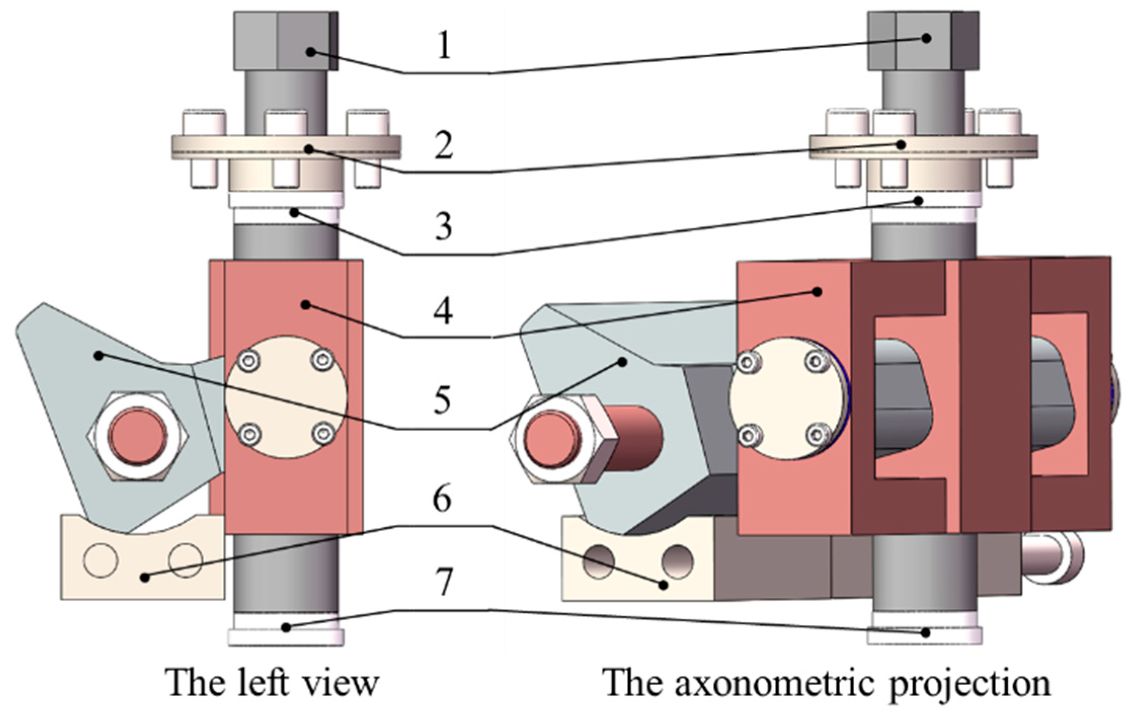
A traditional disc cutter has many unconnected parts, and it is difficult for robots to disassemble and assemble. To realize rapid cutter change by the robot, an integrated disc cutter suitable for robot operation should be designed first. To this end, an integrated disc cutter was designed. The disc cutter is mainly composed of one cutter box, two cutter holders, one disc cutter, two clamping blocks, two cushion blocks, two shift forks, two lifting rods, two thread fastening systems, etc., as shown in Figure 1.
The fastening bolt is installed on the cutter holder through bearings, the fastening bolts and the shift forks are connected by threads, the clamping blocks and the shift forks are hinged, and rotating the fastening bolts can make the clamping blocks swing, as shown in Figure 2. We rotated the fastening bolts to drive the shift forks to move upward along the fastening bolts and then pushed the clamping blocks to swing outwards until they are tightly pressed into the grooves on the cutter holder, and the disc cutter is fixed on the cutter head. Reverse rotation of the fastening bolts can remove the disc cutter from the cutter head.
To implement the assembly and disassembly of the new integrated disc cutter by the robot, it is the first condition to ensure accurate docking between the end-effector of the robot and the fastening bolts of the disc cutter system. To this end, the machining and assembly deviation of the disc cutter system were analyzed, and then, the error capacity of the robot end-effector was designed according to the analysis results.

3. Deviation Analysis of New Integrated TBM Disc Cutter

Position deviation of fastening bolts of the new integrated disc cutter system is the main source of the deviation in the connection of the robot end-effector and the disc cutter fastening bolt. Accurate calculation of the position deviation of the fastening bolts is the basis for the structural design of the cutter-changing end-effector. The deviation sources affecting assembly accuracy include the deviation of geometric location and orientation, variation of geometric form and deviation of part location and orientation [23].
The position deviations of the two fastening bolts of the new integrated disc cutter system mainly come from the following five parts: assembly deviation of the threaded fastening system, FRb; the assembly deviation between the cutter holders and the disc cutter, FRt; the dimensional deviation of the cutter holders and the disc cutter in the direction of the cutter axis, A0; the installation deviation between the cutter holders and the cutter box, FRh; and the welding deviation between the cutter box and the mounting hole of the cutter head, N. Therefore, the position deviations of the fastening bolts can be described as shown in Equation (1).
E = F R b + F R t + A 0 + F R h + N
The deviation FRb can be expressed as:
F R b = u 1 v 1 w 1 α 1 β 1 γ 1 T
where u, v, and w are the translation vector parameters of the axes x, y, and z, respectively. α, β, and γ are the rotation vectors of the x, y, and z axes, respectively. The same goes for the following.
The deviation FRt can be expressed as:
F R t = u 2 v 2 w 2 α 2 β 2 γ 2 T
The deviation A0 can be expressed as:
A 0 = 0 0 w 3 0 0 0 T
The deviation FRh can be expressed as:
F R h = 0 v 4 0 0 0 γ 4 T
The deviation N can be expressed as:
N = 0 0 0 0 β 5 γ 5 T
In summary, the position deviation of the fastening bolts is:
E = u v w α β γ = u 1 + u 2 v 1 + v 2 + v 4 w 1 + w 2 + w 3 α 1 + α 2 β 1 + β 2 + β 5 γ 1 + γ 2 + γ 4 + γ 5

3.1. Analysis of Assembly Deviation of Threaded Fastening System

The deviation of the bolt fastening system is mainly reflected in the angle deviation fα and position deviation fΣ between the actual position and the ideal position of the central axis of the fastening bolt. The main influencing factors are the position and verticality of the fastening bolt mounting hole on the cutter holder, clearance between shaft and hole, etc. To be consistent with the final test model, the disc cutter system model whose size is 1/3 of the actual size is analyzed.

3.1.1. Establishing the Dimensional Chain of the Threaded Fastening System

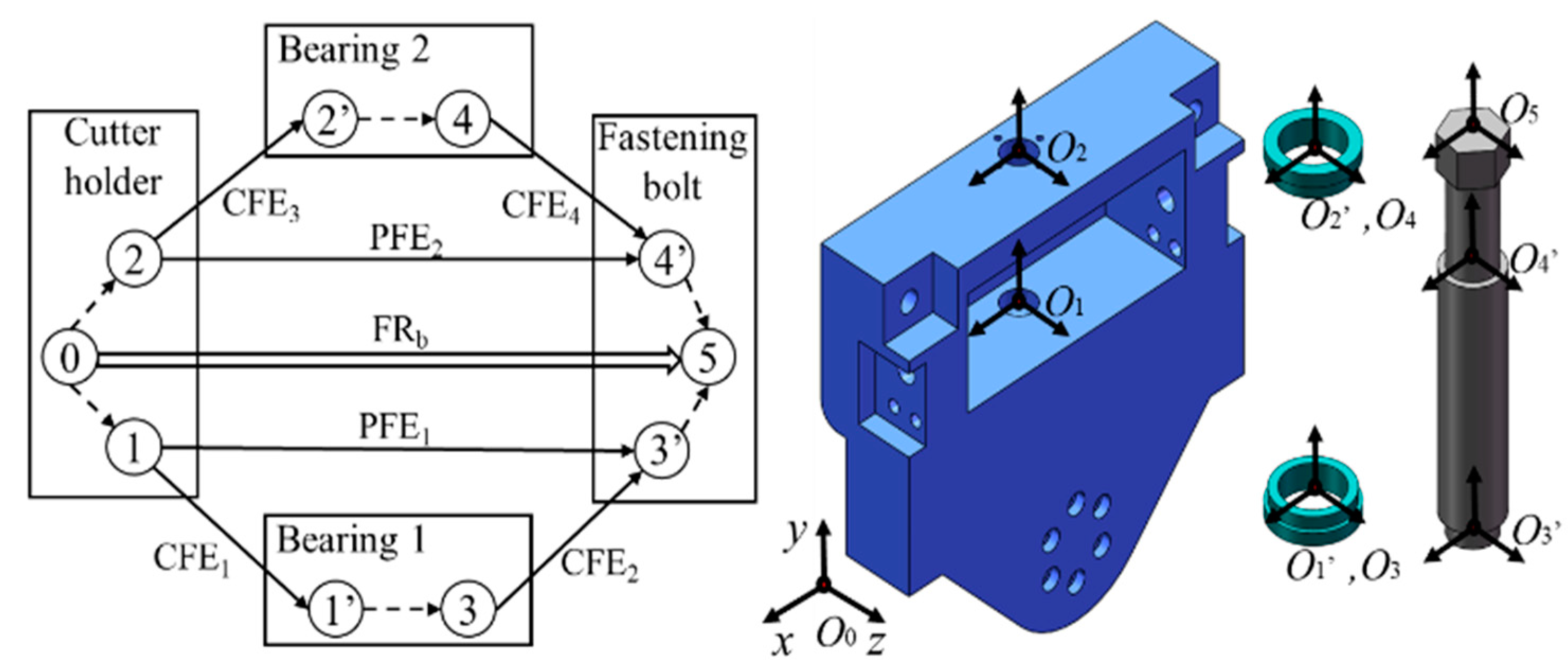
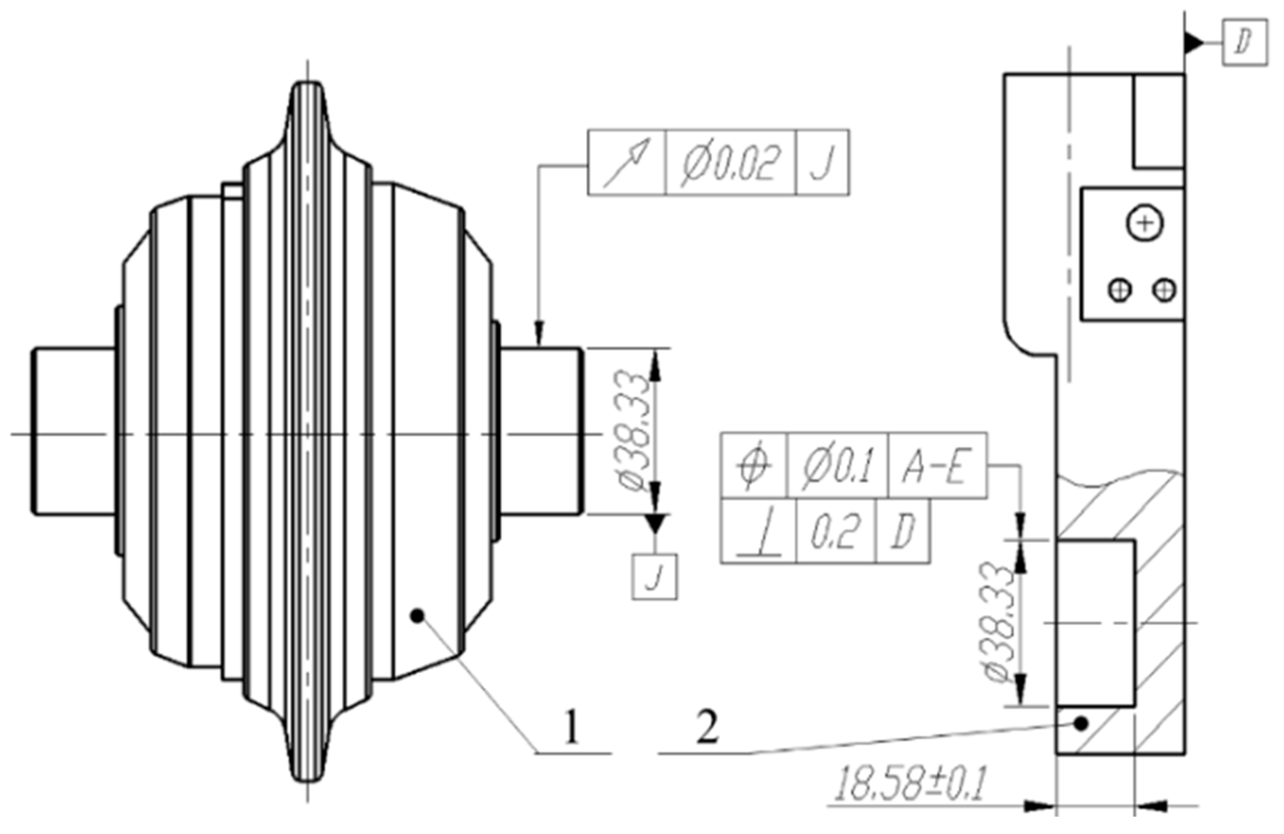
The dimension chain of the thread fastening system was established as shown in Figure 3. The thread fastening system assembly drawing and part tolerances are shown in Figure 4.
As shown in Figure 3, let FRb be the deviation of the fastening bolt in the reference coordinate system 0. The system contains six internal connecting pairs (FE0, FE1), (FE0, FE2), (FE1′, FE3), (FE2′, FE4), (FE3′, FE5), (FE4′, FE5) and four external connecting pairs (FE1, FE1′), (FE2, FE2′), (FE3, FE3′), (FE4, FE4′). Because the load acts on the inner ring of the bearing and the load direction remains unchanged, there is an interference between the inner ring of the bearing and the fastening bolt, and there is a clearance between the outer ring of the bearing and the cutter holder. Clearances are between the bearing outer rings and the cutter holder, i.e., (FE1, FE1′), (FE2, FE2′). Set the dimension chain between the fastening bolt, bearing 1 and the cutter holder as dimension chain 1, i.e., (FE0→FE1→FE1′→FE3→FE3′→FE5). Set the dimension chain between the fastening bolt, bearing 2 and the cutter holder as dimension chain 2, i.e., (FE0→FE2→FE2′→FE4→FE4′→FE5).

3.1.2. Spinor Representation of Tolerance Zone of the Dimension Chains

(1)
Dimension chain 1
① Between bearing 1 and cutter holder
There are two parallel sub-connecting pairs between bearing 1 and the cutter holder. The lower end face of bearing 1 and the end face of the hole on the cutter holder form a face-to-face connecting pair, T1. The clearance between the outer ring of bearing 1 and the hole’s wall on the cutter holder is matched to form a cylindrical surface to the cylindrical surface connecting pair, T2.
According to the accuracy requirements, the tolerance field spinor of T1 is as follows.
u C 1 = w C 1 = 0.022 + 0.015 + 0.02 + 0.02 2 = 0.0385 v C 1 = 0 α C 1 = δ C 1 = 0.022 + 0.015 + 0.02 + 0.02 2.25 = 0.0342 β C 1 = 0
So,
T 1 = 0.0385 0 0.0385 0.0342 0 0.0342 T
According to the accuracy requirements, the tolerance field spinor of T2 is as follows.
u P 2 = w P 2 = 0 v P 2 = 0.02 + 0.02 = 0.0400 α P 2 = δ P 2 = 0.02 + 0.02 10.667 = 0.00375 β P 2 = 0
So,
T 2 = 0 0.0400 0 0.00375 0 0.00375 T
According to the solution method of the local parallel dimension chain [18], the union operation is performed on the three translation parameters of two parallel sub-connecting pairs, and the intersection operation is performed on the three rotation parameters.
So,
C F E 1 = 0.0385 0.0400 0.0385 0.00375 0 0.00375 T
② Between bearing 1 and fastening bolt
There is an interference fit between bearing 1 and the fastening bolt. Therefore, only the surface connection pair composed of the upper-end face of bearing 1 and the shoulder end face of the fastening bolt is considered, and its tolerance field spinor is as follows.
u P 2 = w P 2 = 0 v P 1 = 0.02 + 0.2 + 0.1 = 0.32 α P 1 = δ P 1 = 0.02 + 0.2 + 0.1 8.75 = 0.0366 β P 1 = 0
So,
C F E 2 = 0 0.320 0 0.0366 0 0.0366 T
Then, the Jacobian–Torsor model of dimension chain 1 is as follows.
P F E 1 = J C F E 1 J I F E 3 J C F E 2 T C F E 1 I F E 3 C F E 2 = 0.0385 0.36 0.0385 0.0416 0 0.0416
where
J C F E 1 = diag ( 1 , 1 , 1 , 1 , 1 , 1 ) C F E 1 J C F E 2 = diag ( 1 , 1 , 1 , 1 , 1 , 1 ) C F E 2 J I F E 3 = diag ( 1 , 1 , 1 , 1 , 1 , 1 ) I F E 3 I F E 3 = 0
(2)
Dimension chain 2
① Between bearing 2 and cutter holder
There is a clearance fit between the outer ring of bearing 2 and the mounting hole of the cutter base, so it forms a cylindrical to cylindrical connecting pair. According to the accuracy requirements, its tolerance field spinor is as follows.
u C 3 = w C 3 = 0.022 + 0.015 + 0.02 + 0.02 2 = 0.0385 α C 3 = δ C 3 = 0.022 + 0.015 + 0.02 + 0.02 2.5 = 0.0308
So,
C F E 3 = 0.0385 0 0.0385 0.0308 0 0.0308 T
② Between bearing 2 and fastening bolt
There is an interference fit between the inner ring of bearing 2 and the fastening bolt. Therefore, only the surface connection pair composed of the lower end face of bearing 2 and the end face of the shoulder of the fastening bolt is considered. According to the accuracy requirements, its tolerance field spinor is as follows.
u C 2 = w C 2 = 0.2 + 0.1 + 0.02 2 = 0.160 α C 2 = δ C 2 = 0.2 + 0.1 + 0.02 1.25 = 0.256
So,
C F E 4 = 0.160 0 0.160 0.256 0 0.256 T
So, the Jacobian–Torsor model of dimension chain 2 is as follows.
P F E 2 = J C F E 3 J I F E 5 J C F E 4 T C F E 3 I F E 5 C F E 4 = 0.199 0.0400 0.199 0.261 0 0.261
where
J C F E 3 = diag ( 1 , 1 , 1 , 1 , 1 , 1 ) C F E 3 J C F E 4 = diag ( 1 , 1 , 1 , 1 , 1 , 1 ) C F E 4 J I F E 5 = diag ( 1 , 1 , 1 , 1 , 1 , 1 ) I F E 5 I F E 5 = 0
To sum up, variations of torsor models of the thread-fastening system are shown in Table 1.

3.1.3. Establish Jacobian–Torsor Model

The Jacobian–Torsor model of the local coordinate system 5 of the fastening bolt in the reference coordinate system 0 of the cutter base is established. The local coordinate origin O5 is the center of the upper end face of the fastening bolt.
T a 11 = 0.304 0 0.304 0.00496 0 0.00496 T
J O 0 O 5 = 1 0 0 0 0 35.75 0 1 0 0 0 0 0 0 1 35.75 0 0 0 0 0 1 0 0 0 0 0 0 1 0 0 0 0 0 0 1
F R b = J O 0 O 5 [ T a 11 ] = 0.127 0 0.481 0.00496 0 0.00496

3.2. Calculation of Assembly Deviation between Disc Cutter and Cutter Holders

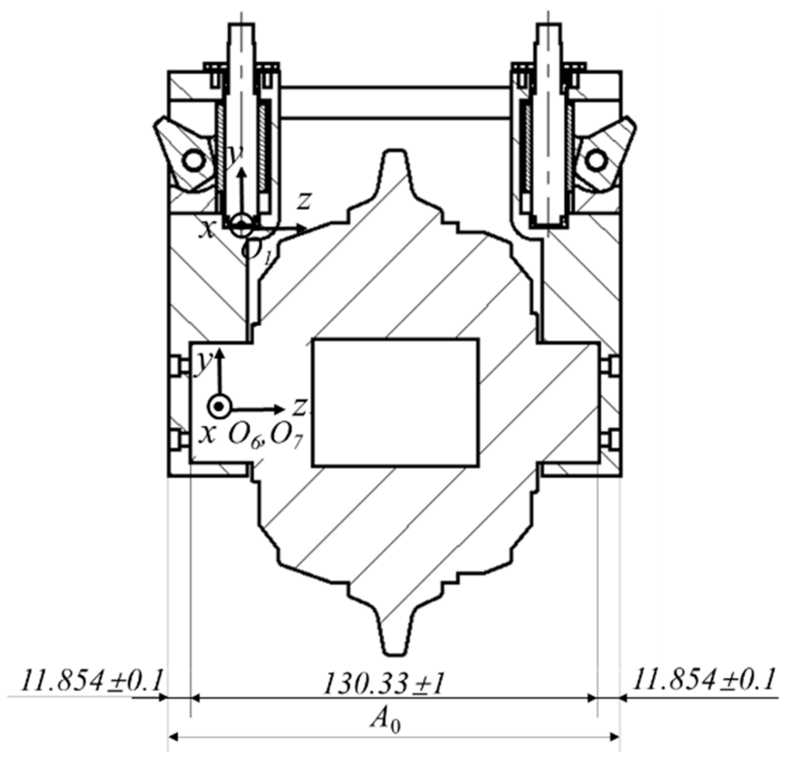
There is a clearance between the disc cutter mounting hole on the cutter holder and the disc cutter shaft, and the two are fastened by bolts. The fit deviation will affect the distance and posture between the two fastening bolts. The deviation is shown in Figure 5. Due to the symmetry of the new integrated disc cutter system, only the right-side matching pair is calculated. The local coordinates are shown in Figure 6.
There are two parallel sub-connection pairs between the mounting hole on the cutter holder and the disc cutter. The cylindrical surface-cylindrical surface connection pair is formed by the inner wall of the mounting hole and the shaft surface of the disc cutter, which is set to T3. The face-face connection pair is formed by the end face of the mounting hole and the end face of the disc cutter shaft, which is set to T4.
According to the accuracy requirements, the tolerance field spinor of T3 is as follows.
u C 6 = w C 6 = 0.033 + 0.021 + 0.1 + 0.2 2 = 0.177 α C 6 = δ C 6 = 0.033 + 0.021 + 0.1 + 0.2 13.94 = 0.0254 v C 6 = β C 6 = 0
So,
T 3 = 0.177 0 0.177 0.0254 0 0.0254 T
According to the accuracy requirements, the tolerance field spinor of T4 is as follows.
u P 5 = w P 5 = 0 v P 5 = 0.02 + 0.02 = 0.0400 α P 5 = δ P 5 = 0.02 + 0.02 28.75 = 0.00139 β P 5 = 0
So,
T 4 = 0 0.0400 0 0.00139 0 0.00139 T
Same with CFR1.
C F R 7 = 0.177 0.0400 0.177 0.00139 0 0.00139 T
The Jacobian–Torsor model of the local coordinate system 7 of the disc cutter in the local coordinate system 1 of the cutter holder is established. According to the relative position of the two, the Jacobian matrix is as follows.
The Jacobian–Torsor model is as follows.
F R t = J C F E 7 [ C F E 7 ] = 0.117 0.0332 0.237 0.00139 0 0.00139
where
J C F E 7 = 1 0 0 0 4.875 43.275 0 1 0 4.875 0 0 0 0 1 43.275 0 0 0 0 0 1 0 0 0 0 0 0 1 0 0 0 0 0 0 1 C F E 7
Then, the assembly deviation between disc cutter and cutter holder is calculated by the extreme value method, and the tolerance is shown in Figure 6.
According to the loop method, all dimensions are added rings. So,
A 0 = [ 0 0 ± 1.2 0 0 0 ] T

3.3. Calculation of Assembly Deviation between Cutter Holders and Cutter Box

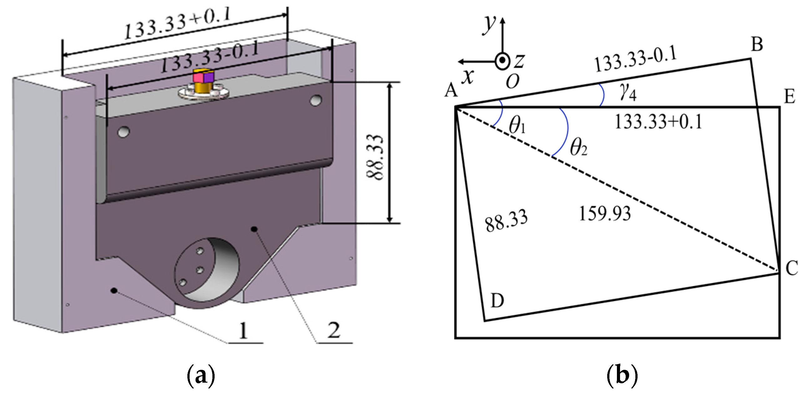
The tolerance of the cutter holder and cutter box is shown in Figure 7a. The clearance fit between the cutter holder and cutter box may cause displacement deviation and angle deviation. The geometric model of angle deviation is shown in Figure 7b.
According to geometric relations, the maximum deviation between the cutter holder and the cutter box is as follows.
F R h = 0.1 0 0 0 0 0.132 T

3.4. Calculation of Welding Deviation between Cutter Box and Cutter Head

The cutter box of the new integrated disc cutter system needs to be welded in the directional mounting hole on the cutter head. The welding seam will cause deviations in the position of the cutter box on the cutter head, which will affect the position of the cutter box in the global coordinate system. The overall dimensions of the cutter box are shown in Figure 8a.
We assume that in the global coordinate system 0, the gap between the cutter box and the mounting hole on the cutter head in the x-axis direction is x, and the gap in the z-axis direction is z. The geometric model is shown in Figure 8b.
In the actual situation, the installation gap between the installation hole on the cutter head and the cutter box is about 10 mm. In the scaled-down disc cutter model, the installation gap is calculated as 3.3 mm, that is, x2max = x3max = 3.3 mm. So, the calculation of welding deviation between the cutter box and the cutter head is as follows.
N = [ 0 0 0 0 1.302 1.304 ] T

3.5. Calculation of Comprehensive Deviation of Fastening Bolt

Through the above analysis and calculation, the various Jacobian–Torsor models in Table 2 can be obtained.
When calculating the comprehensive deviation of the integrated disc cutter system, each spinor parameter takes the maximum value, and the direction of each local coordinate system is consistent with the global coordinate system. The comprehensive spinor of the fastening bolt system of the new integrated disc cutter system can be obtained, as shown in Equation (35).
E = ± 0.344 ± 0.0335 ± 1.918 ± 0.00635 ± 1.302 ± 1.442

3.6. Comprehensive Deviation Envelope Circle of Fastening Bolt Head

Based on the analysis of the assembly deviation of the fastening bolt system, the possible area of the hexagon head of the fastening bolt is studied. The actual fastening bolts of the disc cutter system are non-standard parts, whose specification is M32. In the model reduced by 1:3, we use standard M10 bolts.
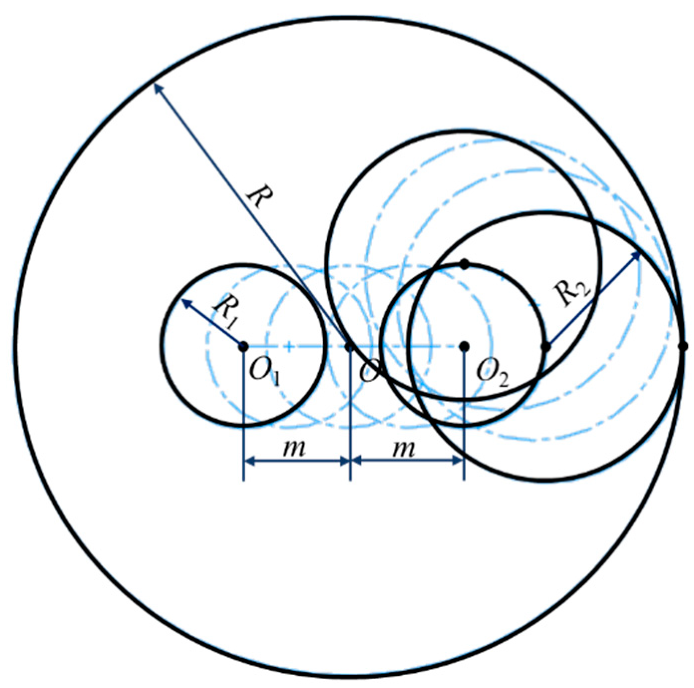
The possible area of the hexagon head of the fastening bolt is a circular area with the ideal position of the bolt’s central axis as the center and R as the radius. The comprehensive deviation envelope circle is shown in Figure 9.
R = m + R 1 + R 2
where m is the assembly deviation between the cutter holder and the disc cutter in the direction of the disc cutter’s central axis, m = ±0.6 mm.
R1 is the larger of the components u1 and (w1m) of the composite deviation FRb of the disc cutter system, R1 = max{u1, w1m} = 1.351 mm.
R2 is the circumscribed radius of the hexagon head of the fastening bolt, R2 = 9.24 mm.
So, R = m + R1 + R2 = 11.191 mm.

3.7. The Measurement of the Position Deviation of the Fastening Bolts of the New Integrated Disc Cutter System

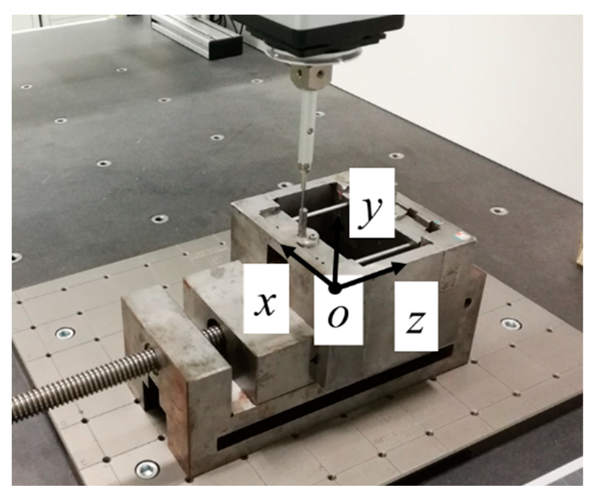
We use the coordinate measuring machine to measure the scaled-down model of the new integrated disc cutter system. We establish the coordinate system as shown in Figure 10. The position and angle deviations in the y-axis direction are not considered. The ideal position and angle deviation of the two fastening bolts’ center axis are as follows.
101.100 0 36.700 0 0 0 T
101.100 0 154.01 0 0 0 T
Ignore the welding deviation between the cutter box and the cutter head. The theoretical position deviation of fastening bolts is as follows.
± 0.344 0 ± 1.918 ± 0.00635 0 ± 0.138 T
After measuring the coordinate position of each point of the disc cutter system, according to the spatial coordinate value of these points, through mathematical calculations, the actual position and angle deviations of the two fastening bolts’ center axis can be obtained.
100.875 0 37.804 0.00517 0 0.131 T
101.287 0 153.497 0.00419 0 0.145 T
Compared to the ideal state, the deviation of position and angle deviations of the two fastening bolts’ center axis are as follows.
+ 0.225 0 + 1.104 0.00517 0 0.131 T
0.187 0 0.513 0.00419 0 0.145 T
The results show that the angular deviation of fastening bolt 2 as it winds around the z-axis is more than 5% of the theoretical calculation range. The rest are within the theoretical range. Therefore, the deviation analysis method is reasonable.

4. Design of the End-Effector of Supporting Cutter-Changing Robot

For the above-mentioned integrated disc cutter, the end-effector of the robot has been designed, that is, a universal wrench for fastening bolts. There is a relative position deviation between the axis of the robot end-effector and the axis of the fastening bolt (Deviation 1), and there is a phase deviation between the head of the fastening bolt and the universal wrench (Deviation 2). For these two kinds of deviations, the end-effector of the cutter-changing robot needs to complete the radial and circumferential automatic positioning.

4.1. Overall Structure Design of End Effector of Cutter-Changing Robot

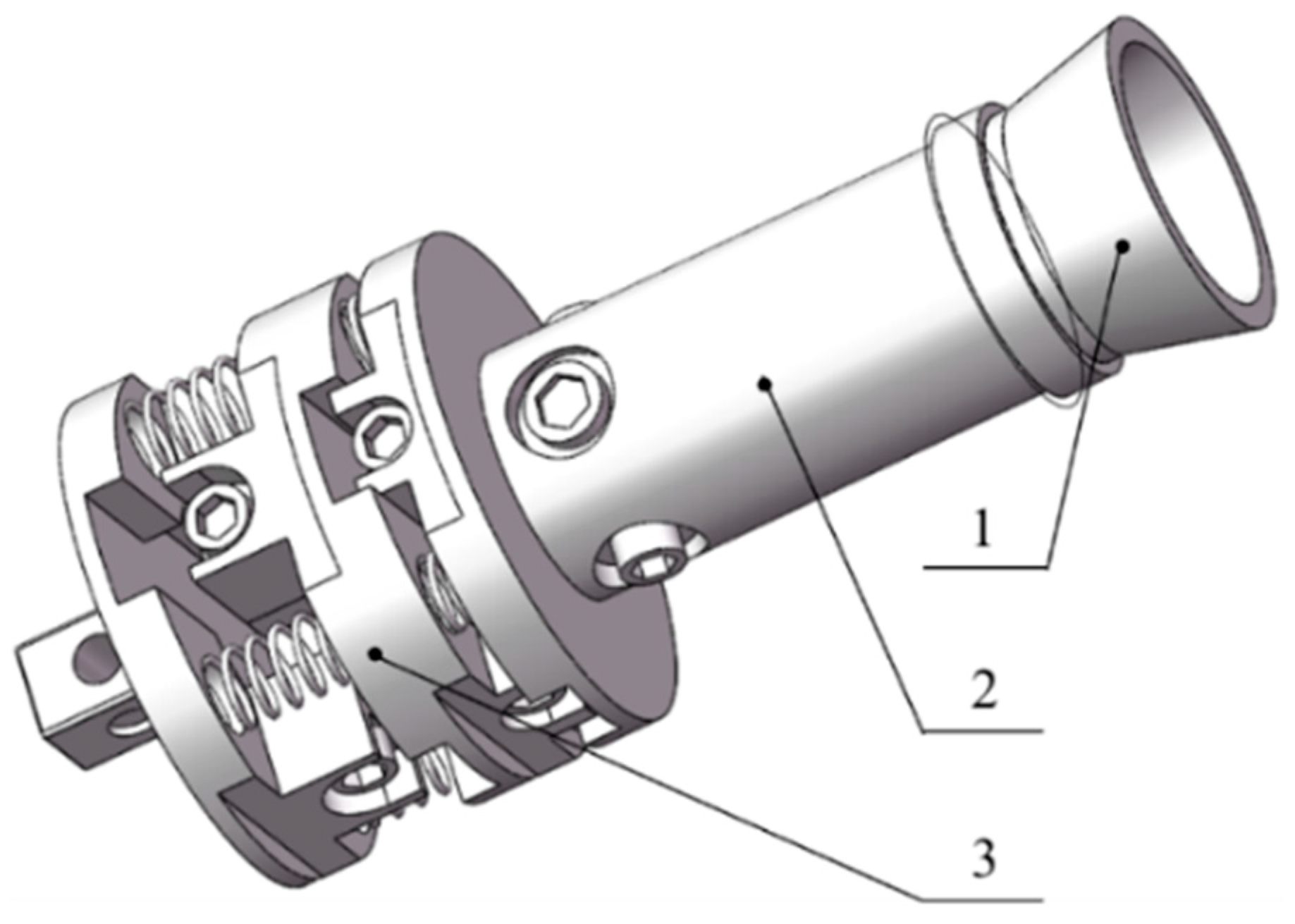
The structure of the cutter-changing robot end-effector is shown in Figure 11.
Aiming at Deviation 1, a cone-shaped guiding mechanism is designed. The guiding mechanism is similar to the horn type. When working, the head of the disc cutter fastening bolt enters from the trumpet-shaped big end of the guiding mechanism, slides along its inner wall to the small end of the guiding mechanism, and reaches the main body of the universal wrench. The guiding mechanism can contain a certain degree of relative position deviation between the axis of the universal wrench and the axis of the fastening bolt through the conical structure.
When the universal wrench at the end of the robot rotates the bolt, the above Deviation 1 will cause the universal wrench rotation eccentrically. Therefore, a flexible terminal connecting mechanism is designed. The mechanism consists of two universal joints, which can achieve a certain degree of eccentric transmission.
Aiming at the above Deviation 2, a universal wrench is designed. The universal wrench is composed of a sleeve and multiple steel bars. When working, the steel bars in contact with the end face of the bolt are pressed down, and the steel bars around the bolt fix the head of the bolt to apply torque to the bolt. The mechanism can accommodate fastening bolts at any angle.

4.2. Parametric Design of End-Effector of Supporting Cutter-Changing Robot

According to the assembly deviation analysis results of the new integrated disc cutter system, the parametric design of the universal wrench is carried out.

4.2.1. Parametric Design of the Guiding Mechanism

The basic parameters of the guiding mechanism include the diameter of the big end a, the diameter of the small end b, and the length l, as shown in Figure 12a.
(1)
The diameter of the big end a
The diameter of the big end of the guiding mechanism shall be greater than the diameter of the comprehensive deviation envelope circle of the fastening bolt head of the disc cutter system, D3, taking the safety factor of 1.2, then, a = 1.2D3 = 16.8594 mm.
(2)
The diameter of the small end b
The diameter of the small end of the guiding mechanism is equal to the diameter of the circumscribed circle of the regular hexagon with the circumscribed circle of the fastening bolt head as the inscribed circle, as shown in Figure 12b.
b = 2 R 2 cos 30 °
R2 is the circumscribed radius of the fastening bolt head, R2 = 9.24 mm.
(3)
The length of the guiding mechanism l
The length of the guiding mechanism shall not affect the swing angle of the universal joint of the flexible connecting mechanism.

4.2.2. Parametric Design of the Universal Wrench

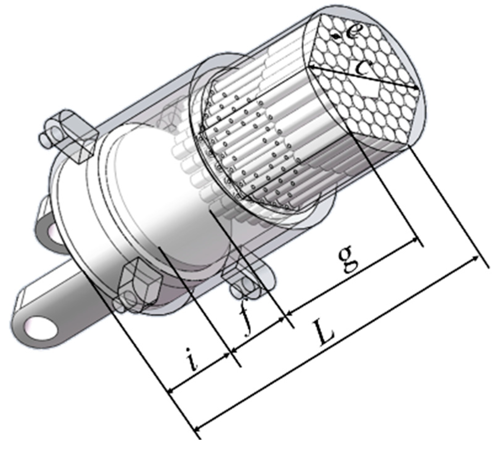
The basic structural parameters of the universal wrench include the diameter of the circumscribed circle of the hexagonal inner hole c, the diameter of the steel bar e, the working depth of the steel bar f, the telescopic distance of the steel bar h, the length of the steel bar g, the height of the base i, and the total length of the universal wrench L, as shown in Figure 13.
(1)
The diameter of the circumscribed circle of the hexagonal inner hole, c
The diameter of the circumscribed circle of the hexagonal inner hole of the universal wrench c is equal to the diameter of the small end of the guiding mechanism, b.
c = b = 2 R 2 cos 30 °
(2)
The diameter of the steel bar, e
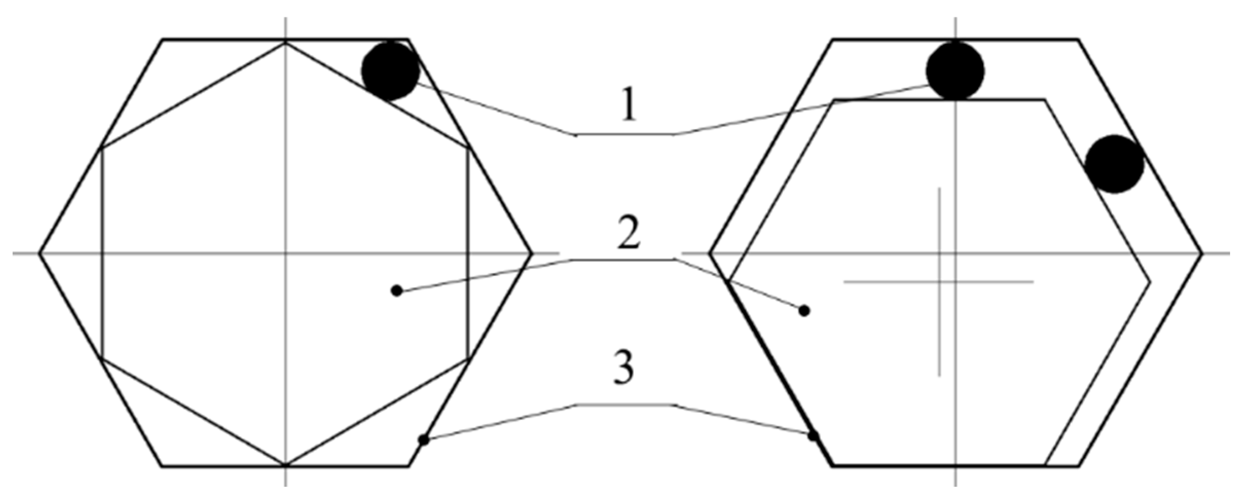
The diameter of the steel bar should satisfy that the universal wrench can clamp the bolt at any angle, as shown in Figure 14. It can be obtained from geometric relations.
e = R 2 ( 3 + tan 30 ° ) × cos 30 °
(3)
The working depth of the steel bar, f
The working depth of the steel bar refers to the distance that the hexagonal head of the disc cutter system fastening bolt pushes the telescopic steel bar.
The working depth of the steel bar should be slightly less than the length of the bolt head. Set the length of the fastening bolt head of the scaled-down disc cutter system model as lB, lB = 6.4 mm.
f = l B 2
(4)
The telescopic distance of the steel bar, h
The retractable distance of the steel bar shall be slightly greater than the working depth of the steel bar, f.
h = f + 2
(5)
The length of the steel bar, g
The steel bar includes the following three parts: the front part for clamping the bolt head, the back part that is fixed on the sleeve, and the middle part between them. Its lengths are set as g1, g2, and g3, respectively, as shown in Figure 15.
The g1 should be slightly longer than the working depth of the steel bar, f.
g 1 = f + 2
The g2 shall be slightly longer than the working depth of the steel bar, f, and the sum of the installation thickness of the steel bar p.
g 2 = f + p + 2
The g3 shall ensure that the steel bar is stably fixed and less than the working depth of the steel bar f.
So,
g = g 1 + g 2 + g 3 = 2 f + p + 4 + g 3
(6)
The height of the base, i
The height of the base shall ensure sufficient strength requirements.
(7)
The total length of the universal wrench, L
The length of the universal wrench includes the length of the steel bar g, the working depth of the steel bar f, and the height of the limit base i.
L = g + f + i

4.2.3. Parametric Design of the Flexible Connecting Mechanism

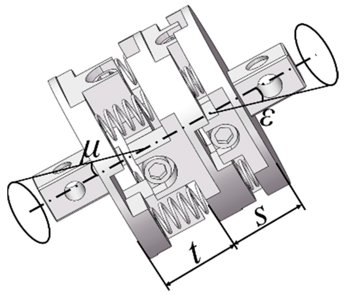
The flexible connecting mechanism consists of two universal joints. Let the rod length of universal joint 1 be s and the angle be ε. Let the rod length of universal joint 2 be t and the angle be μ, as shown in Figure 16.
When the universal wrench is butted with the fastening bolt, the deviation includes radial deviation z and angular deviation θ1.
Z = R 1 + L + m
θ 1 = max { α , β } + θ y
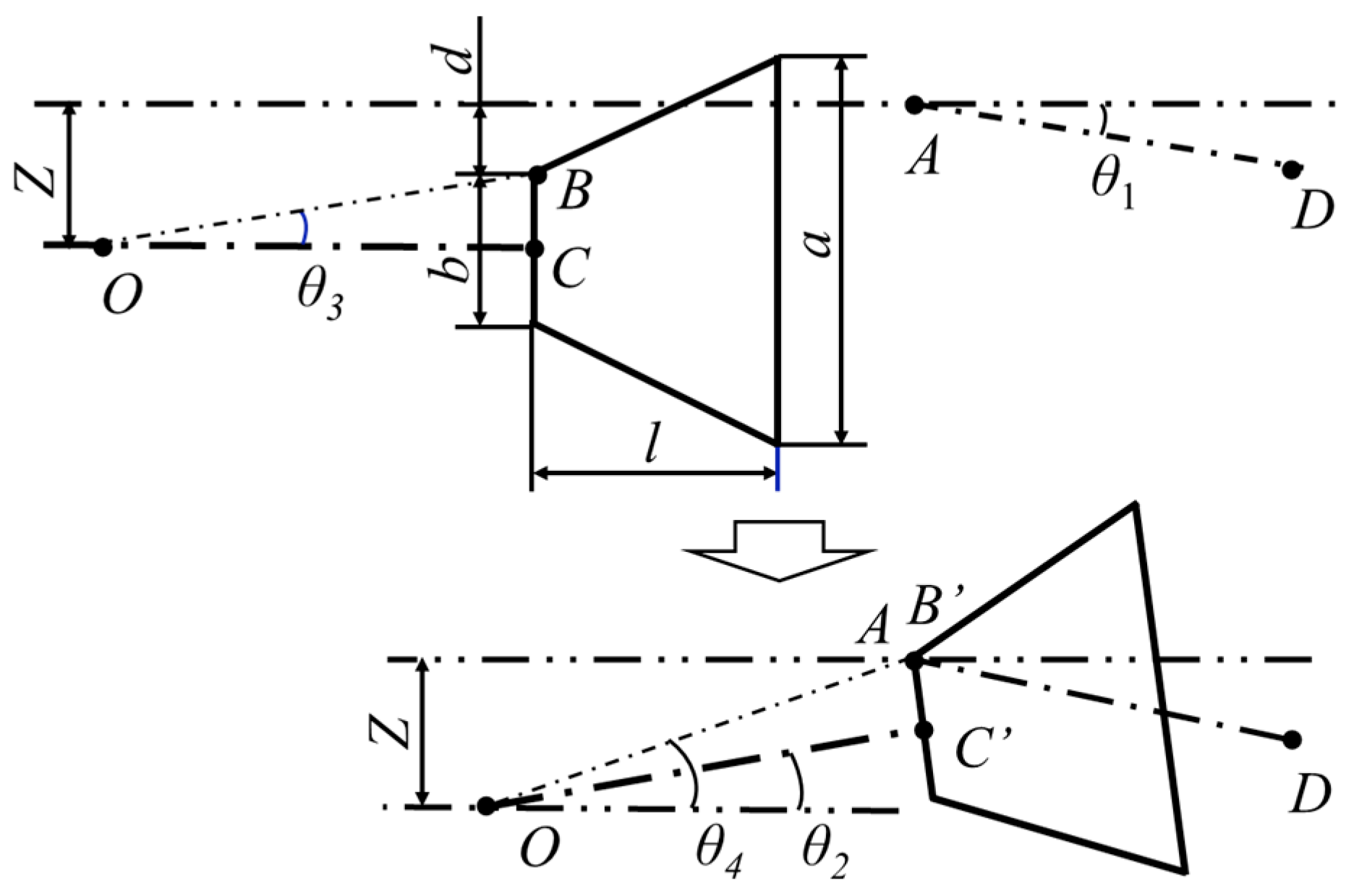
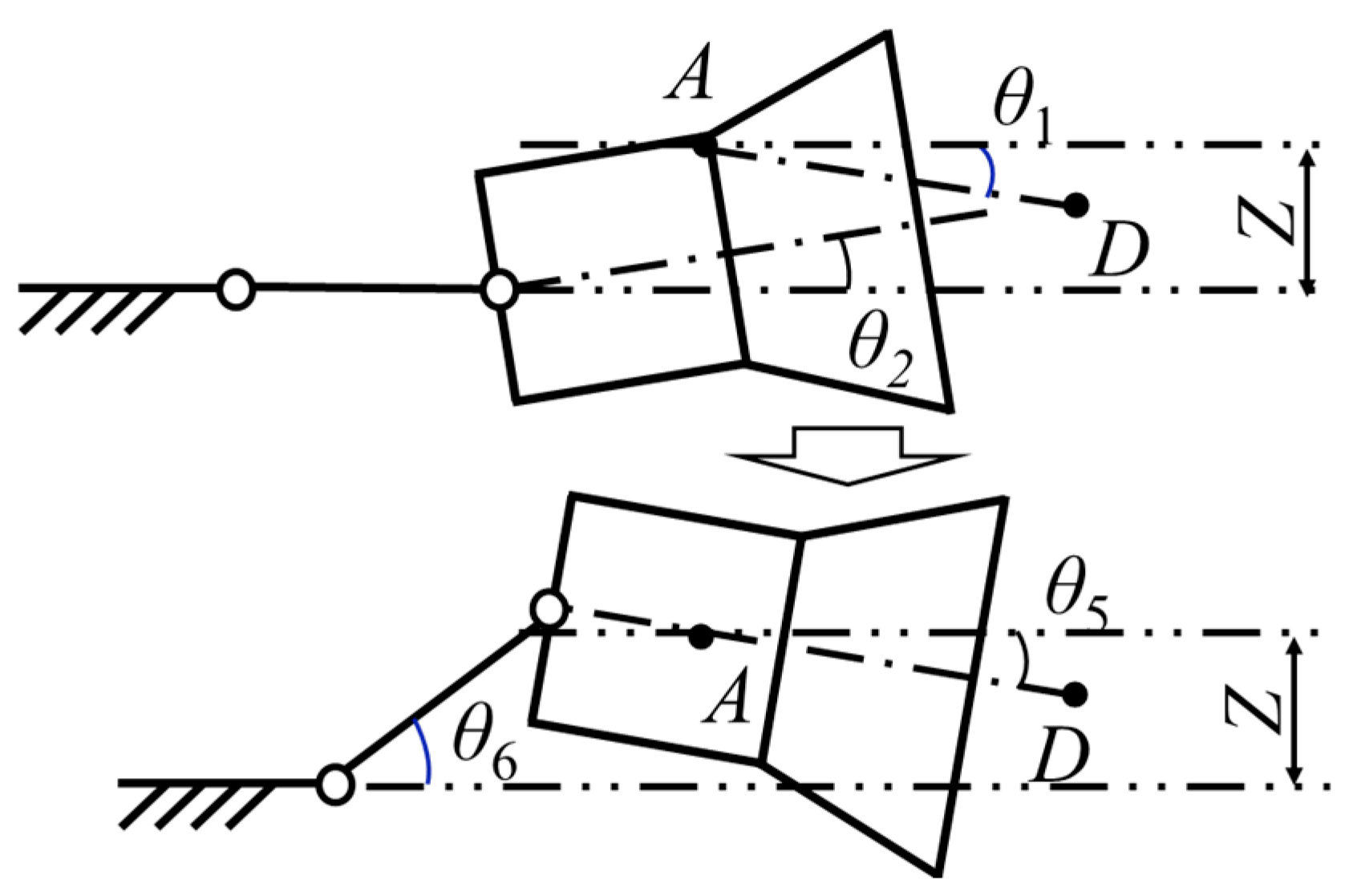
When the universal wrench is docked with the fastening bolt, the fastening bolt enters the guiding mechanism. Due to the radial deviation and the angle deviation, the axes of the two are not collinear and not parallel, and the guiding mechanism will rotate around the universal joint 1 by an angle of θ2. During the process of the universal wrench jamming the bolt, the flexible connecting mechanism rotates to eliminate this angle deviation.
(1)
Determination of the rotation angle of the universal joint 1, ε
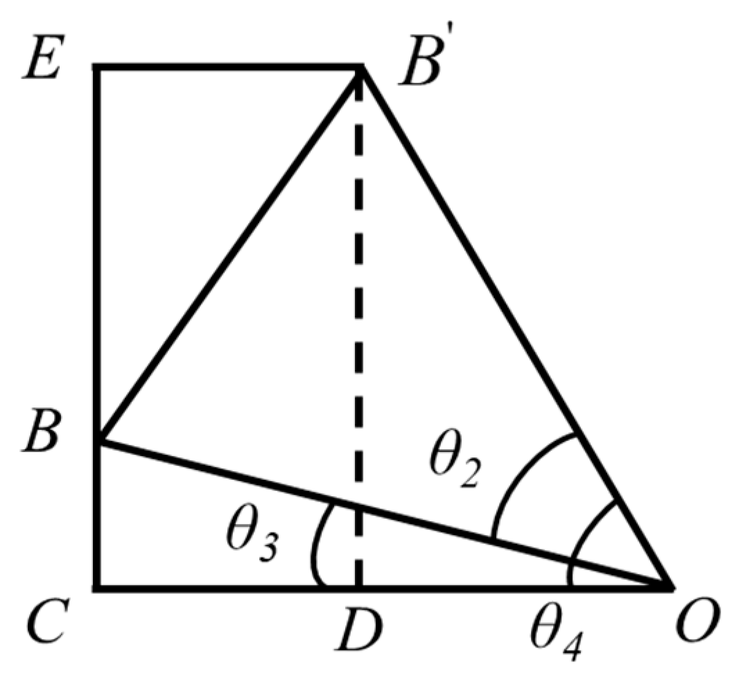
The connecting process of the guiding mechanism and the fastening bolt is shown in Figure 17, and the geometric relationship of each parameter is shown in Figure 18.
Suppose the distance from the small end section of the guiding mechanism to the center of rotation of the universal joint 1 is OB = j. The radius of the small end of the guide cone is BC. In the figure, AD is the axis of the disc cutter tightening bolt.
To ensure reliability, take the safety factor of 1.2. Then, according to the geometry:
ε = 1.2 × max θ 1 , θ 2 = 1.2 × max max α , β , arcsin max u , v - m + m j arcsin R 2 j × cos 30
(2)
Determination of the rotation angle of the universal joint 2, μ
The process of connecting the end-effector of the cutter-changing robot with the bolt is shown in Figure 19. In this process, the universal joint 2 rotates at an angle θ6, and the universal joint 1 rotates at an angle θ5 in a reverse direction so that the axis of the tightening bolt is parallel to the axis of the universal wrench. There are two cases of eccentricity and non-eccentricity, and the eccentric distance k is the radius of the steel bar, that is, k = e/2.
Under the condition that there is no eccentricity between the universal wrench and the fastening bolt, the schematic diagram of the universal wrench and the bolt is shown in Figure 20a. When there is an eccentricity k between the universal wrench and the fastening bolt, the schematic diagram of the universal wrench and the bolt is shown in Figure 20b.
In the figure, HI is equal to the working depth of the universal wrench steel bar, f. To ensure reliability, take the safety factor of 1.2, then,
μ = 1.2 × max θ 6 ,   θ 6 = 1.2 × max arc   sin ( L   +   s     f )   ×   sin ( max α ,   β )   +   max u ,   v - m   +   m t , ( L   +   s   +   f ) sin ( max α ,   β )   +   max u ,   v - m   +   m     e 2   ×   cos ( max α ,   β ) t

4.3. The Simulation Analysis of End-Effector of the Cutter-Changing Robot

4.3.1. Function Simulation Analysis of End Effector

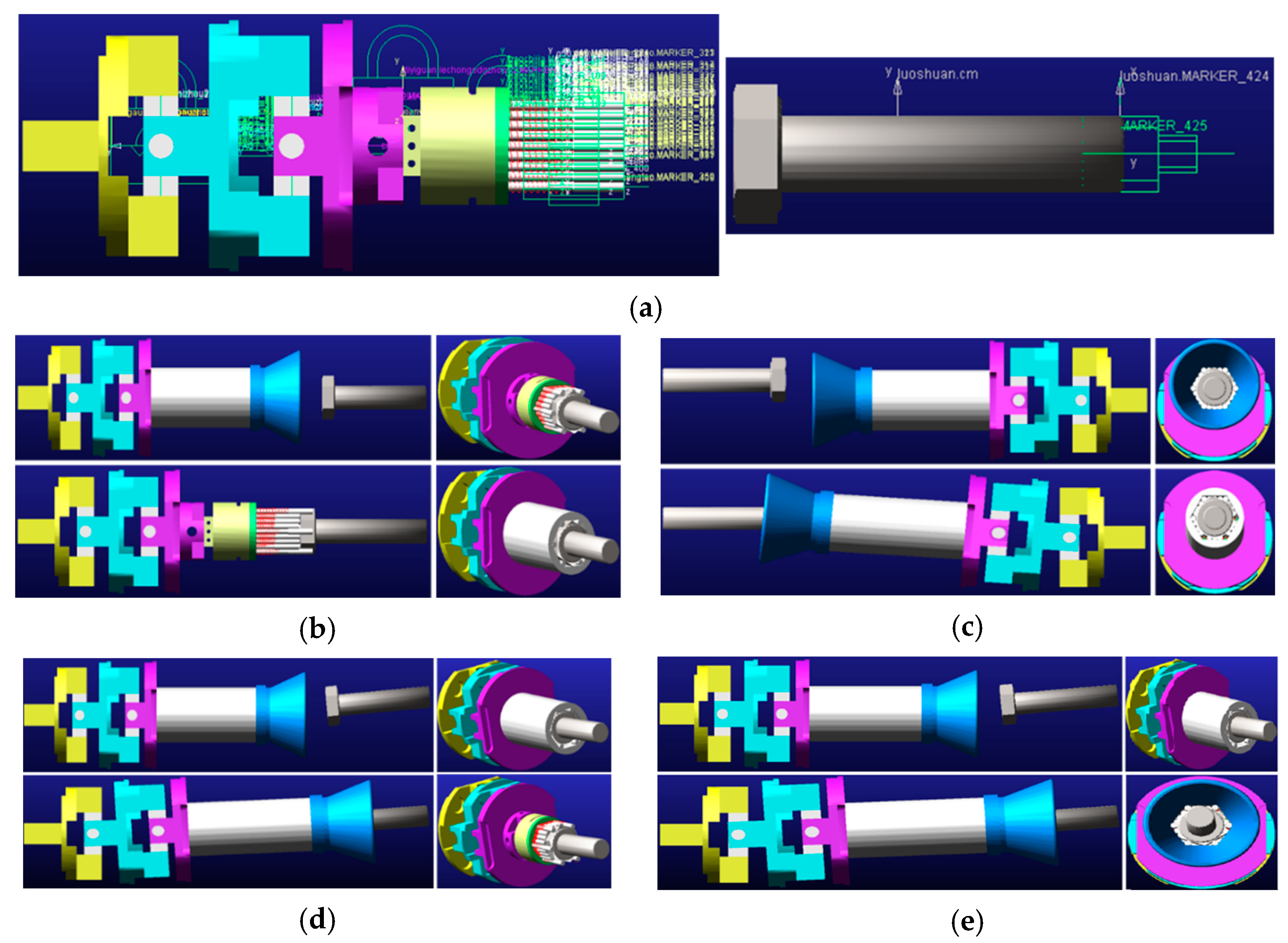
Verify the docking function of the end-effector based on ADAMS software. Add connecting kinematic pairs and forces according to the actual situation, as shown in Figure 21a, and conduct docking simulation without initial error, single radial displacement error, single angular displacement error and comprehensive error, as shown in Figure 21b–e. In the comprehensive error envelope circle of the end with a radius of 13.48 mm, the maximum deviation angle of the axis of 8.65° can be docked successfully, which verifies the docking function of the end-effector.

4.3.2. Simulation Analysis of Mechanical Properties of Key Structures

When the end effector of the cutter-changing robot works, the universal wrench is the most loaded part, and the flexible connecting mechanism is one of the weak parts. Therefore, the finite element analysis is mainly carried out in these two parts. The material of the universal wrench is 35CrMo, and its performance parameters are shown in Table 3. The flexible connection mechanism is made of 20CrMnTi, and its mechanical properties are shown in Table 4.
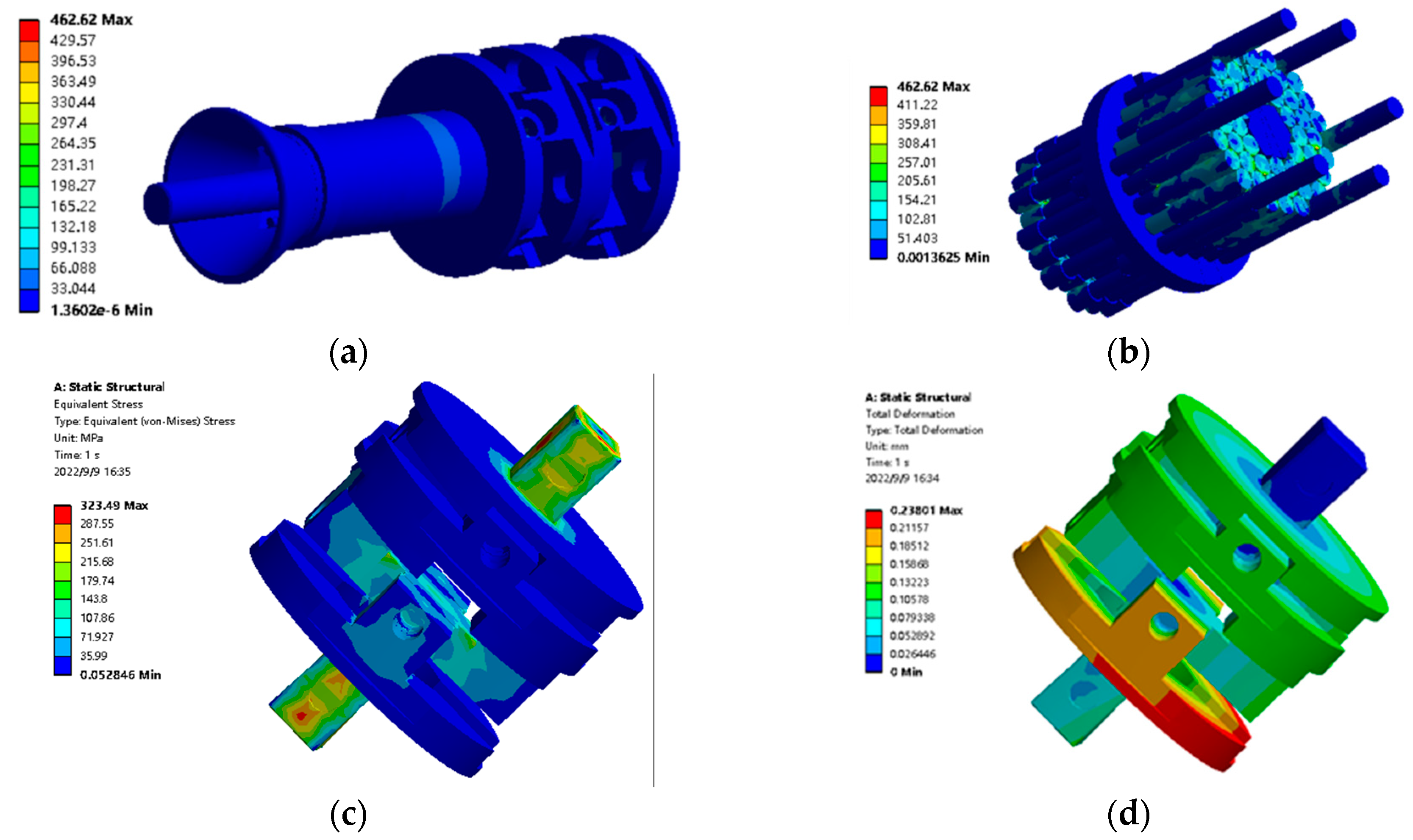
After the necessary simplification of the flexible connection mechanism model established by SolidWorks, it is imported into ANSYS/workbench, given materials and meshed. A fixed constraint is imposed on one end of the end effector installed on the robot based on the actual contact type between the components. Friction contact is set between the bolt and the movable steel bar, and the friction coefficient is set to 0.2. Apply fixing constraints to the bolts. The scale model of the new TBM integrated hob adopts 6.8 grade M10 standard bolts. According to the mechanical design manual, the tightening torque of bolts is required to be 33–45 N∙m. A moment of 45 nm is applied to the second joint driving shaft of the flexible connection structure. The final analysis results are shown in Figure 22.
Through the finite element analysis results, it can be found that under the torque of 45 N∙m, the maximum stress of the universal wrench is 462.62 MPa. It is located in the movable steel bar structure inside the universal sleeve, and the safety factor of the structure can reach 1.8. The maximum stress of the flexible connection mechanism is 323.49 MPa and the maximum strain is 0.238 mm, which is less than the yield strength (835 MPa), which can meet the requirements. Therefore, the structural performance of the universal cone sleeve designed can meet the actual working conditions of the disc cutter changing.

4.4. The Universal Wrench Performance Test

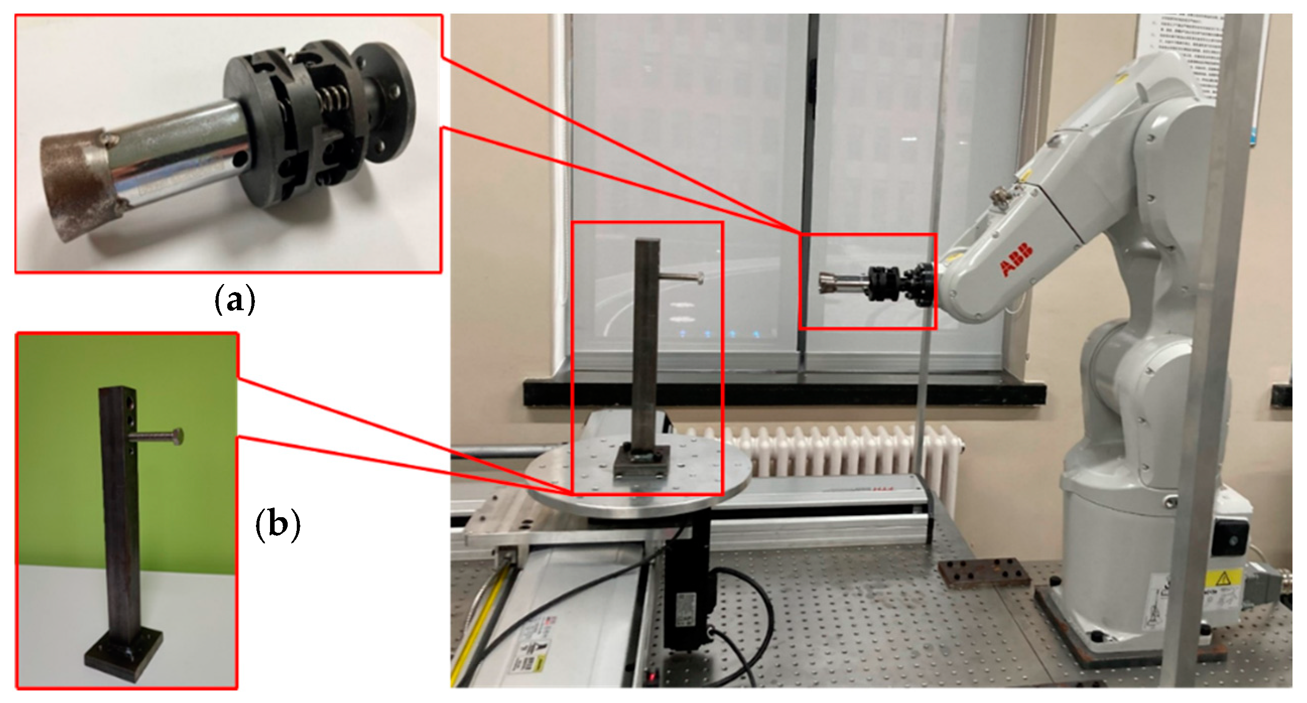
To verify the designed end-effector of the cutter-changing robot in this paper and whether it can meet the functional requirements, a model of the cutter-changing robot end-effector for the scaled-down model of the disc cutter system is made. The disc cutter system is simplified. The cutter-changing robot end-effector and the simplification device of the fastening bolt were mounted on the test bench, as shown in Figure 23.
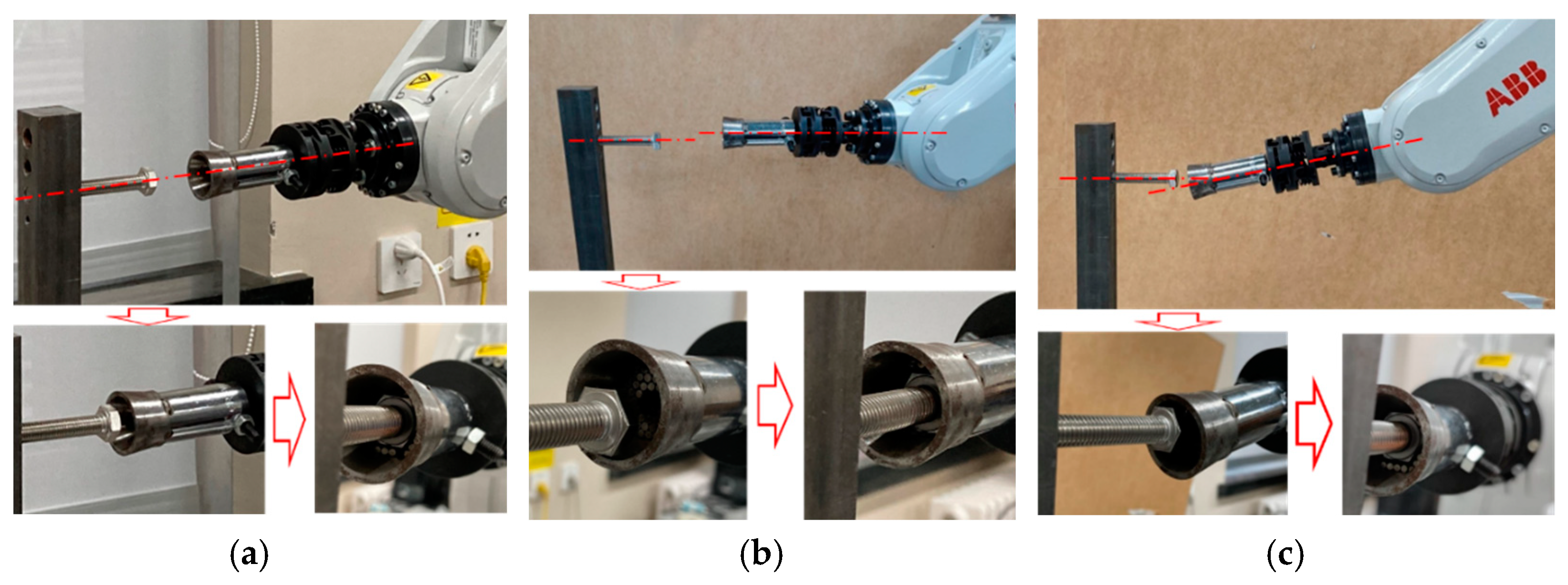
Taking the axis of the fastening bolt as the test benchmark, by adjusting the pose of the end effector of the cutter-changing robot, the docking conditions are set to no deviation, radial displacement deviation, and angular deviation, as shown in Figure 24. The size of the docking deviation is determined through the robot posture displayed on the robot operation panel.
First, carry out the docking experiment without deviation, and adjust the experimental device to the ideal state; that is, the bolt axis and the end effector axis are collinear, as shown in Figure 24a.
Next, the butt joint experiment with radial deviation was carried out, as shown in Figure 24b. Since the deviation is relative, the posture of the bolt is kept unchanged, and the radial deviation is set by adjusting the posture of the end of the robot. Starting from no deviation, after the first docking is successful, the deviation gradually increases until the docking failure, and the maximum radial deviation tolerance of the end-effector is obtained.
Figure 24c is a docking experiment with angular deviation. Start from the position without deviation, and then gradually increase the included angle between the bolt axis and the end-effector axis by changing the robot’s end attitude. A total of several docking experiments were carried out until the docking could not be completed to measure the maximum angular deviation tolerance of the robot end effector.
The experimental results show that when there is a radial deviation of 3.55 mm between the cutter-changing robot end-effector and the bolt, which accounts for 19.21% of the diameter of the circumscribed circle of the hexagon head of the bolt, the reduced scaled-down universal wrench can fully butt with the fastening bolt. The same result is obtained when there is an 11° angle deviation between the two, which can meet the actual engineering requirements.
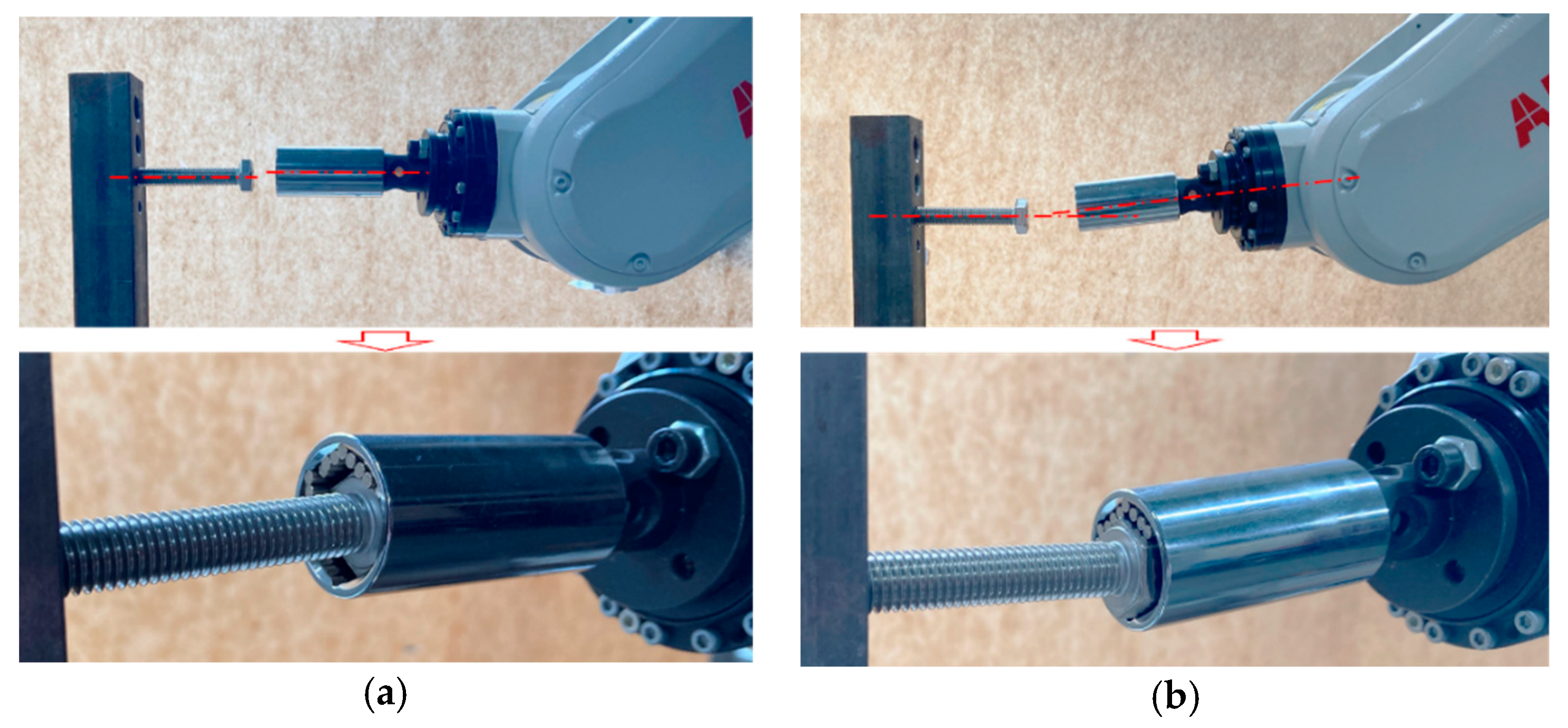
Figure 25 shows the docking of the traditional universal wrench and the bolt. The experimental process is the same as the above-mentioned experimental process for the end-effector of the cutter-changing robot. The maximum radial deviation that the traditional universal wrench can accommodate is 2 mm. When the angle deviation is greater than 5°, the traditional universal wrench and bolt cannot be docked. Therefore, it can be found that compared with the traditional universal wrench, the performance of the end-effector of the cutter-changing robot mentioned in this paper is much better, and it can better meet the performance requirements of using a robot to change the TBM disc cutter.

5. Conclusions

(1)
In this paper, the improved Jacobian–Torsor model is used to analyze the deviation of a new integrated disc cutter system of TBM developed by our research group. The experiment results show that the deviation analysis method is reasonable and accurate. Among the 10 deviation components tested, only one exceeds the theoretical calculation range by 5%.
(2)
Based on deviation analysis of the new integrated TBM disc cutter, an end-effector of a cutter-changing robot matched was designed, and a scaled-down sample was made for the test. The functions of each part of the end-effector of the cutter-changing robot can meet the expected requirements. The scaled-down cutter-changing robot end-effector can accommodate a radial deviation of 3.55 mm and an angular deviation of 11°.

Author Contributions

Funding acquisition, J.H.; Investigation, F.Y.; Methodology, H.L.; Project administration, J.H.; Validation, H.C.; Writing—original draft, H.C. and H.L.; Writing—review and editing, B.Y. All authors have read and agreed to the published version of the manuscript.

Funding

This work was supported by the National key R & D plan of China (Grant No. 2018YFB1306701) and the National Natural Science Foundation of China (Grant No. 51875076).

Institutional Review Board Statement

Not applicable.

Informed Consent Statement

Not applicable.

Data Availability Statement

The data presented in this study are available on request from the authors.

Conflicts of Interest

The authors declare no conflict of interest.

References

  1. Camus, T.; Manacorda, G. European Project NeTTUN–Making it happen. In ITA WTC 2015 Congress and 41st General Assembly; Lacroma Valamar Congress Center: Dubrovnik, Croatia, 2015. [Google Scholar]
  2. Derycke, J.N.; Rubrecht, S. Method for Replacing a Tunnel Boring Machine Disk Cutter, Handling Device and Disk Cutter Suited to Such a Method. U.S. Patent US20130045055A1, 30 August 2016. [Google Scholar]
  3. Mansard, N.; Khatib, O.; Kheddar, A. A unified approach to integrate unilateral constraints in the stack of tasks. IEEE Trans. Robot. 2009, 25, 670–685. [Google Scholar] [CrossRef]
  4. Camus, T.; Moubarak, S. Maintenance robotics in TBM tunnelling. In ISARC. Proceedings of the International Symposium on Automation and Robotics in Construction; IAARC Publications: Berlin, Germany, 2015. [Google Scholar]
  5. Chu, B.; Jung, K.; Ko, K.H.; Hong, D. Mechanism and analysis of a robotic bolting device for steel beam assembly. In Proceedings of the ICCAS 2010, Gyeonggi-do, Korea, 27–30 October 2010. [Google Scholar]
  6. Zhang, Q.; Xie, Z.; Liu, Y.; Liu, H. Development of Bolt Screwing Tool Based on Pneumatic Slip Ring. In 12th International Conference on Intelligent Robotics and Applications (ICIRA); Springer International Publishing Ag: Shenyang, China, 2019. [Google Scholar]
  7. Li, R.; Pham, D.T.; Huang, J.; Tan, Y.; Qu, M.; Wang, Y.; Kerin, M.; Jiang, K.; Su, S.; Ji, C.; et al. Unfastening of Hexagonal Headed Screws by a Collaborative Robot. IEEE Trans. Autom. Sci. Eng. 2020, 17, 1455–1468. [Google Scholar] [CrossRef]
  8. DiFilippo, N.M.; Jouaneh, M.K. A System Combining Force and Vision Sensing for Automated Screw Removal on Laptops. IEEE Trans. Autom. Sci. Eng. 2018, 15, 887–895. [Google Scholar] [CrossRef]
  9. Zhang, Q.; Xie, Z.; Liu, Y.; Zhao, X.; Gu, Y.; Liu, H. A novel approach for flexible manipulator conducting screwing task based on robot-environment contact classification. Proc. Inst. Mech. Eng. Part C-J. Mech. Eng. Sci. 2021, 235, 1357–1367. [Google Scholar] [CrossRef]
  10. Chen, H.; Jin, S.; Li, Z.; Lai, X. A comprehensive study of three dimensional tolerance analysis methods. Comput.-Aided Des. 2014, 53, 1–13. [Google Scholar] [CrossRef]
  11. Hong, Y.; Chang, T. A comprehensive review of tolerancing research. Int. J. Prod. Res. 2002, 40, 2425–2459. [Google Scholar] [CrossRef]
  12. Clement, A.; Riviere, A. Tolerancing versus nominal modeling in next generation CAD/CAM system. In Proceedings of the 3rd CIRP Seminar on Computer Aided Tolerancing, ENS de Cachan, Cachan, France, 27–28 April 1993. [Google Scholar]
  13. Laifa, M.; Sai, W.B.; Hbaieb, M. Evaluation of machining process by integrating 3D manufacturing dispersions, functional constraints, and the concept of small displacement torsors. Int. J. Adv. Manuf. Technol. 2014, 71, 1327–1336. [Google Scholar] [CrossRef]
  14. Davidson, J.; Mujezinovic, A.; Shah, J. A new mathematical model for geometric tolerances as applied to round faces. J. Mech. Des. 2002, 124, 609–622. [Google Scholar] [CrossRef]
  15. Jaishankar, L.N.; Davidson, J.K.; Shah, J.J. Tolerance analysis of parallel assemblies using tolerance-maps® and a functional map derived from induced deformations. In ASME International Design Engineering Technical Conferences and Computers and Information in Engineering Conference (IDETC/CIE); American Society of Mechanical Engineers: Portland, OR, USA, 2013. [Google Scholar]
  16. Barbero, B.R.; Azcona, J.P.; Pérez, J.G. A tolerance analysis and optimization methodology. The combined use of 3D CAT, a dimensional hierarchization matrix and an optimization algorithm. Int. J. Adv. Manuf. Technol. 2015, 81, 371–385. [Google Scholar] [CrossRef]
  17. Jin, S.; Chen, H.; Li, Z.; Lai, X. A small displacement torsor model for 3D tolerance analysis of conical structures. Proc. Inst. Mech. Eng. Part C J. Mech. Eng. Sci. 2015, 229, 2514–2523. [Google Scholar] [CrossRef]
  18. Zeng, W.; Rao, Y.; Wang, P.; Yi, W. A solution of worst-case tolerance analysis for partial parallel chains based on the Unified Jacobian-Torsor model. Precis. Eng.-J. Int. Soc. Precis. Eng. Nanotechnol. 2017, 47, 276–291. [Google Scholar] [CrossRef]
  19. Gao, J.; Chase, K.W.; Magleby, S.P. Generalized 3-D tolerance analysis of mechanical assemblies with small kinematic adjustments. IIE Trans. 1998, 30, 367–377. [Google Scholar] [CrossRef]
  20. Liu, Y. Typical Russian space docking mechanism and its characteristics. Spacecr. Eng. 1994, 3, 33–38. [Google Scholar]
  21. Günther, H.; Knoop, H.U. Implication and usefulness of spacecraft servicing at the ISS using the pilot case of the large X-ray facility XEUS. Acta Astronaut. 2003, 53, 645–650. [Google Scholar] [CrossRef]
  22. Zhang, L.; Shao, J.; Zhou, H. Analysis and Optimization of Force Transmissibility and Kinematic Performance of Low Impact Docking Mechanism. Manned Spacefl. 2015, 21, 462–467. [Google Scholar]
  23. Liu, W. Mechanism Analysis of Deviation Sourcing and Propagation for Mechanical Assembly. J. Mech. Eng. 2012, 48, 156–168. [Google Scholar] [CrossRef]
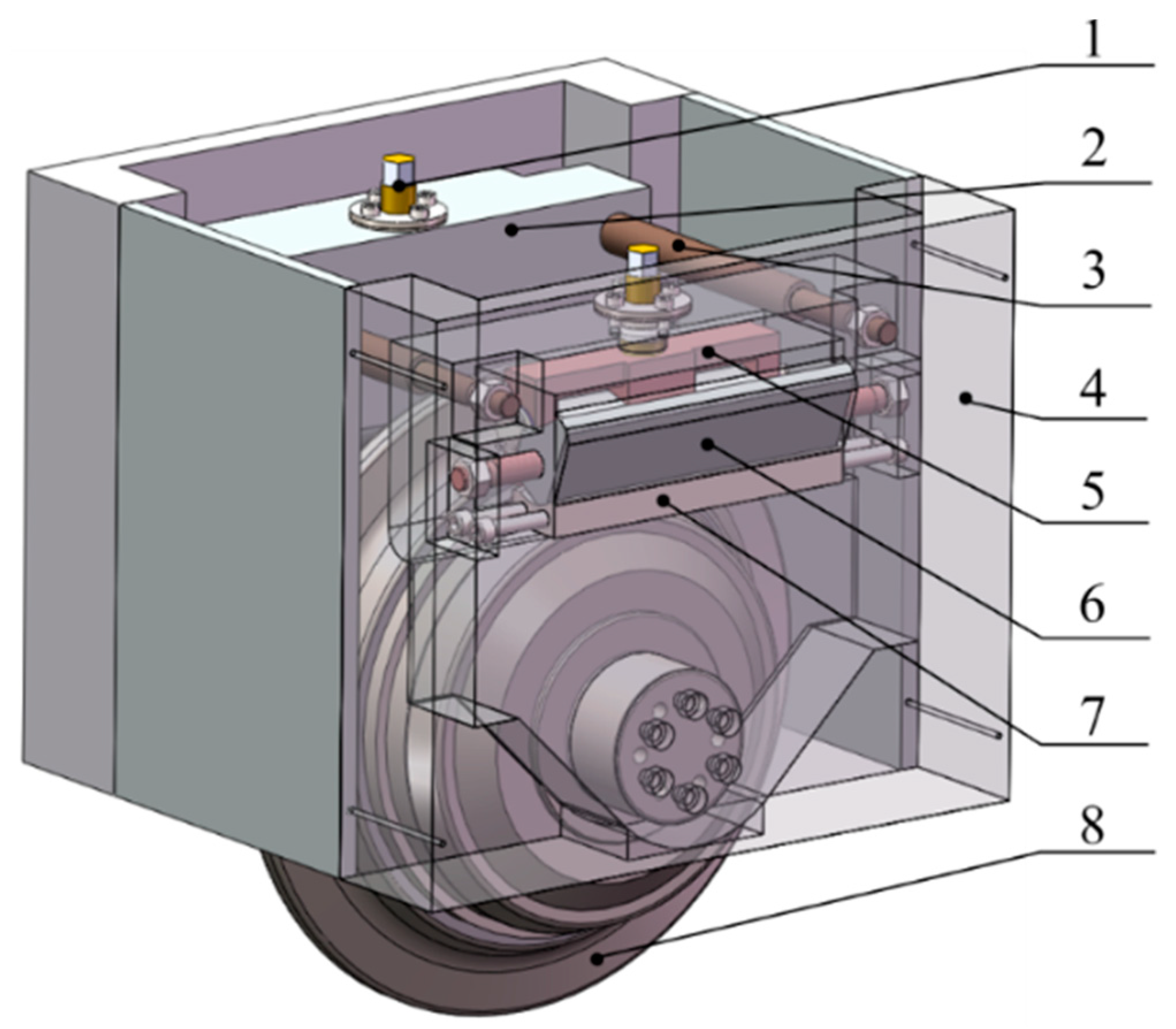
Figure 1. New integrated TBM disc cutter. 1—Thread fastening system, 2—Cutter holder, 3—Lifting rod, 4—Cutter box, 5—Shift fork, 6—Clamping block, 7—Cushion block, 8—Disc cutter.
Applsci 12 09549 g001
Figure 2. Thread fastening system. 1—Fastening bolt, 2—Bearing cap, 3—Bearing, 4—Shift forks, 5—Clamping block, 6—Cushion block, 7—Bearing.
Applsci 12 09549 g002
Figure 3. Dimensional chains of threaded fastening system.
Applsci 12 09549 g003
Figure 4. Part tolerances of thread fastening system. 1—Fastening bolt, 2—Cutter holder.
Applsci 12 09549 g004
Figure 5. Tolerance of disc cutter and cutter holder. 1—Disc cutter, 2—Cutter holder.
Applsci 12 09549 g005
Figure 6. Local coordinates of cutter holder and disc cutter.
Applsci 12 09549 g006
Figure 7. Assembly deviation between cutter holders and cutter box. (a) Dimensions of cutter holder and cutter box. 1—Cutter box, 2—Cutter holder. (b) The geometric model of angle deviation between cutter holder and cutter box.
Applsci 12 09549 g007
Figure 8. The welding deviation between cutter box and cutter head. (a) Overall dimensions of the cutter box. (b) The geometric model of angle deviation between the cutter box and the mounting hole of the cutter head.
Applsci 12 09549 g008
Figure 9. The comprehensive deviation envelope circle of the fastening bolt head of the new integrated disc cutter system.
Applsci 12 09549 g009
Figure 10. Reference coordinate system.
Applsci 12 09549 g010
Figure 11. The end-effector of the cutter-changing robot. 1—The guiding mechanism, 2—The universal wrench, 3—The flexible connecting mechanism.
Applsci 12 09549 g011
Figure 12. Parametric design of the guiding mechanism. (a) Parameters of the guiding mechanism. (b) Diameter of the guiding mechanism’s small end.
Applsci 12 09549 g012
Figure 13. Structural parameters of the universal wrench.
Applsci 12 09549 g013
Figure 14. Matching relation between steel bars and bolt. 1—The steel bar, 2—The bolt, 3—The guiding mechanism’s small end.
Applsci 12 09549 g014
Figure 15. Component of steel bar.
Applsci 12 09549 g015
Figure 16. Parameters of the flexible connecting mechanism.
Applsci 12 09549 g016
Figure 17. The connecting process of the guiding mechanism and the fastening bolt.
Applsci 12 09549 g017
Figure 18. The geometric relationship between the guiding mechanism and the fastening bolt.
Applsci 12 09549 g018
Figure 19. The process of connecting the universal wrench with the bolt.
Applsci 12 09549 g019
Figure 20. The schematic diagram of connecting the universal wrench with the bolt. (a) No eccentricity. (b) Eccentricity.
Applsci 12 09549 g020
Figure 21. Function simulation analysis of end effector. (a) Add motion pair and force. (b) Docking without initial deviation. (c) Docking with radial deviation. (d) Docking with an angular deviation. (e) Docking with comprehensive deviation.
Applsci 12 09549 g021
Figure 22. Finite element analysis results. (a) Global stress distribution of end-effector. (b) Stress distribution of steel bars. (c) Stress distribution of flexible connecting mechanism. (d) Strain distribution of flexible connecting mechanism.
Applsci 12 09549 g022
Figure 23. The test bench. (a) The universal wrench. (b) The fastening bolt simplification device.
Applsci 12 09549 g023
Figure 24. Docking tests. (a) The docking condition without deviation. (b) The docking condition with radial deviation. (c) The docking condition with angle deviation.
Applsci 12 09549 g024
Figure 25. Docking experiment of traditional universal wrench and bolt. (a) The docking condition with radial deviation. (b) The docking condition with angle deviation.
Applsci 12 09549 g025
Table 1. Variations of torsor models of the thread-fastening system.
ParameterTolerance Zone
CFE1 ± 0.0385 ± 0.0400 ± 0.0385 ± 0.00375 0 ± 0.00375 T
CFE2 0 ± 0.320 0 ± 0.0366 0 ± 0.0366 T
CFE3 ± 0.0385 0 ± 0.0385 ± 0.0308 0 ± 0.0308 T
CFE4 ± 0.160 0 ± 0.160 ± 0.256 0 ± 0.256 T
PFE1 ± 0.0385 ± 0.360 ± 0.0385 ± 0.0416 0 ± 0.0416 T
PFE2 ± 0.1985 ± 0.0400 ± 0.1985 ± 0.261 0 ± 0.261 T
Table 2. Jacobian–Torsor models of the deviation of each part of the new integrated disc cutter system.
ParametersPhysical SignificanceTolerance Zone
FRbAssembly deviation between fastening bolt and cutter holder [ ± 0.127 0 ± 0.481 ± 0.00496 ± 0 ± 0.00496 ] T
FRtAssembly deviation between disc cutter and cutter holders [ ± 0.117 ± 0.0332 ± 0.237 ± 0.00139 ± 0 ± 0.00139 ] T
A0The deviation between cutter holders and disc cutter in the direction of cutter shaft [ 0 0 ± 1.20 0 0 0 ] T
FRhAssembly deviation between cutter holders and cutter box [ ± 0.1 0 0 0 0 ± 0.132 ] T
NWelding deviation between cutter box and cutter head [ 0 0 0 0 ± 1.302 ± 1.304 ] T
Table 3. The mechanical properties of 20CrMnTi.
Density
(kg/m3)
Elastic Modulus
(GPa)
Poisson RatioTensile Strength
(MPa)
Yield Strength
(MPa)
78002070.251080835
Table 4. The mechanical properties of 35CrMo.
Density
(kg/m3)
Elastic Modulus
(GPa)
Poisson RatioTensile Strength
(MPa)
Yield Strength
(MPa)
78502100.31080835
Publisher’s Note: MDPI stays neutral with regard to jurisdictional claims in published maps and institutional affiliations.