Article

Temperature Effect on Electrical Resistivity Measurement Using an Embedded Sensor to Estimate Concrete Water Content

1
MAST-LAMES, Campus de Nantes, Univ Gustave Eiffel, F-44344 Bouguenais, France
2
LMDC (Laboratoire Matériaux et Durabilité des Constructions), INSA, UPS, Université de Toulouse, 135, Avenue de Rangueil, CEDEX 04, F-31077 Toulouse, France
3
L2MGC, CY Cergy Paris Université, F-95000 Cergy, France
4
Andra, French National Radioactive Waste Management Agency, F-92298 Chatenay-Malabry, France
*
Author to whom correspondence should be addressed.
Appl. Sci. 2022, 12(19), 9420; https://doi.org/10.3390/app12199420
Submission received: 11 July 2022 / Revised: 11 August 2022 / Accepted: 18 August 2022 / Published: 20 September 2022
(This article belongs to the Special Issue The State of the Art in Non-destructive Evaluation of Concrete)

Abstract

:
Concrete resistivity measurements strongly depend on the temperature and the water content of the structure. In this paper, a study of the effect of the temperature and saturation degree on electrical resistivity measurement is carried out using an embedded printed circuit board sensor to estimate water content profiles in concrete structures. Resistivity measurements are performed at temperatures between 20 and 60 °C. Experimental results are presented and analyzed in light of well-established empirical models. Calibration curves that link the electrical resistivity to the degree of saturation at a given temperature are discussed. Arrhenius laws that depend on the degree of saturation can be used to fit our data. In the perspective of the instrumentation and monitoring of concrete structure in real conditions, it is important to master the temperature correction laws of resistivity measurement to evaluate the gradients of water saturation degree.

1. Introduction

The optimized monitoring of a structure must be considered from the design of the structure and carried out as soon as it is built. One of the phenomena to be monitored to ensure its physical durability is the mechanical strength of the concrete structure [1]. Thus, the delayed ettringite formation, deleterious to mechanical properties of thick structures, is provoked by an excessive temperature increase at an early age and by a high ambient water content [2] which must be measured for effective durability modeling [3]. Meanwhile, corrosion of the reinforcements is the main degradation factor of reinforced concrete structures and is a consequence of a number of causes which may not always be independent. These can be carbonation, the penetration of chloride ions, or internal swelling reactions. The parameter conditioning their development is the water content of the concrete; therefore, this is considered as one of the main parameters governing the durability of reinforced concrete structures [1].
Several non-destructive techniques, such as electromagnetic methods, are used to characterize the water content in concrete [4,5,6,7,8]. Among these methods, the DC-electrical resistivity technique [9,10,11] is proven to be highly sensitive to the water content as described by Archie’s law [12]. Other factors can affect the electrical resistivity measurements, among which we can cite the formulation and microstructure of the concrete (pore structure, connectivity and tortuosity of the porosity, water–cement ratio, cementitious content, etc.), the presence of metallic reinforcements [10,13,14,15], and the variations in environmental measurement conditions (temperature, relative humidity, etc.) [14,16,17].
Rasch and Hinrichsen [18] showed that the temperature has a notable effect on concrete resistivity; thus, controlling the temperature is necessary [19]. The temperature of the concrete influences the concentration and mobility of the ions and the ion–ion and ion–solid interactions [20]; therefore, it affects the measured resistivity [21,22], as well the electromagnetic permittivity [23]. These interactions can be different for cements of different chemical composition (e.g., slag or fly ash). This influence varies according to the concrete water content [14]. For a constant relative humidity (RH), an increase in the temperature of the concrete implies a decrease in the resistivity [14].
For simplicity, it can be assumed that, in the range of temperature between 0 °C and 40 °C, the resistivity doubles when temperature decreases by 20 °C, or that the resistivity varies, either from 3% to 5% per °C (per 1.8 °F) [21,24] or from 1.8% to 2.2–3% per °C in geophysical applications [19,25]. In controlled laboratory conditions, resistivity is affected by the temperature at which the measurement is taken. On site, seasonal changes lead to temperature variation in the concrete structures exposed to various environmental conditions, affecting the resistivity of the structures. Therefore, it is necessary to consider the temperature effect to enhance the relevance of the resistivity measurement in thick concrete structures.
This article presents a study of the effect of concrete temperature on the electrical resistivity measurement using a novel multi-electrode embedded sensor. This sensor was developed by Badr et al. [26] in order to monitor the water content gradient through the thickness of radioactive waste storage tunnels for the French national radioactive waste management agency (Andra). The coupled influence of the temperature and the degree of saturation on the resistivity measurements is studied for the sensor embedded along the entire structure thickness.
For this purpose, several experiments were carried out on cylindrical specimens having a diameter of 11 cm and a length of 22 cm (standard specimen geometry) and made from the same concrete formulation and procedure. The sensor allows a large quantity of experimental data to be collected. It scans the concrete vertically every centimeter and allows two measurement configurations. Electrical resistivity measurements were carried out at different temperatures and degrees of saturation to establish calibration curves that link the electrical resistivity with the degree of saturation at different temperatures. Wide ranges of temperature [20–60 °C] and of saturation degree [34–95%] were studied, corresponding to the need dictated by the application long-term monitoring in radioactive waste storage tunnels with exothermic reactions. The correlation between resistivity and temperature was analyzed using the Arrhenius law. A validation for this methodology was conducted for various degrees of saturation.

2. Methods and Materials

In this section, we present the measurement method with an embedded sensor of resistivity, temperature correction models, and the experimental process of this study.

2.1. Electrical Resistivity Measurements

The electrical resistivity characterizes the ability of the material to oppose the flow of electric current. A method for measuring the resistivity of a medium is the four-point electrodes method where the current I (A) is injected via two electrodes and the potential drop ΔV (V) is measured between two other electrodes. The resistivity is connected to the electrical resistance (ΔV/I) by a geometric factor G (m) that depends on the geometry of the structure as well as the configuration of the electrodes. The factor G is numerically determined by a finite element calculation using COMSOL Multiphysics® in a homogeneous medium. In the case of a medium with moisture gradients, an “apparent” resistivity ρa (Ω.m) is inferred for each of the electrode’s configuration, using Equation (1):
ρ a = G Δ V I   .
In this study, we considered all the specimens in homogeneous moisture and temperature conditions; thus, the resistivity was assumed to be constant within the specimens and the measured apparent resistivities provided a good approximation of the resistivity (ρa = ρ).
To make an electrical resistivity measurement, it is possible to carry out either a surface measurement [27,28] or a measurement in depth using an embedded device [4,29]. The use of embedded sensors offers the possibility of evaluating the concrete resistivity throughout a large thickness of the structure without the inherent loss of resolution with depth. In this study, electrical resistivity measurements were conducted using an embedded printed circuit board (PCB) sensor developed by Badr et al. [26]. The PCB sensor has a ladder-like shape which improves the anchorage of the electrodes in the concrete. In this study, we used 19 electrodes, each with dimensions of 3 × 1.5 mm2, placed on either side of the sensor with an inter-electrode spacing of 2 cm on each side (Figure 1).
Two measurement configuration modes are considered for this PCB sensor [26]. The first mode is the transmission configuration where I is injected on two stainless steel grids (Ø = 10 cm) placed on either side of the sensor and ΔV is measured between all pairs of consecutive electrodes located on the same side of the sensor (E1E3, E2E4, E3E5, …, E17E19) (Figure 1). The second mode is the Wenner configuration, where the quadrupole measurements C1P1P2C2 (where electrodes C1 and C2 are used for current injection, and electrodes P1 and P2 are used for potential drop measurements) are successively E1E3E5E7, E2E4E6E8, E3E5E7E9, …, E13E15E17E19 (Figure 1).
For both configurations, Badr et al. [26] showed that the apparent resistivity is a good estimation of the true resistivity at the middle of the electrodes where the potential is measured. Therefore, the measurements obtained along the sensor length can be seen as a resistivity profile with depth in concrete. Since all specimens are in homogeneous moisture and temperature conditions in this study, we expected measured resistivity profiles to exhibit flat trends over depth with comparable values between the two measurement configurations, assuming that there is no structural variability in each specimen.

2.2. Temperature Correction Models

Several temperature correction models have been published. In one approach, a linear relationship applicable to electrolytic solutions can be used to describe the temperature effect on concrete resistivity [30,31]:
ρ T = ρ T 0 [ 1 + α ( T 0 T ) ]
where ρT (Ω.m) is the resistivity of the material measured at a temperature T (°C), ρT0 (Ω.m) is the resistivity of the material measured at a reference temperature T0 (°C), and α (°C−1) is a temperature coefficient depending on the nature of the material. Values of α for concrete have been reported ranging from 0.022 to 0.035 °C−1 [30,31]. Some authors advocate that a linear law such as Equation (2) is the most convenient to standardize resistivity measurements in practical applications [16,20].
In another approach, Arrhenius types of relations [16,20,31,32,33] are used as a popular method to describe the effect of temperature on electrical resistivity:
ρ T = A exp ( E a R T )
where ρT (Ω.m) is the resistivity of the material measured at a temperature T (K), A (Ω.m) is the nominal resistivity when T (K) → ∞, R = 8.314 J mol−1 K−1 (the universal gas constant), and Ea (J/mol) is the activation energy for resistivity which quantifies the amount of thermal energy required to promote a mole of the ions in concrete pore solution from equilibrium state to activated state [34]. Values of Ea have been reported to range from 16.9 kJ/mol to 42.77 kJ/mol [4,16], depending on the degree of saturation and the microstructure properties [35]. It was emphasized that using a constant value of Ea for all types of concrete could lead to misleading results [31,36].

2.3. Experimental Program

The concrete formulation (Table 1) used in this study was based on cement type I (CEM I) with a water–cement ratio of 0.59 and a porosity of 15.3 ± 0.3%, and with a maximum aggregate size of 12.5 mm.
Five PCB sensors were embedded in five cylindrical specimens (numbered from S1 to S5) of 11 cm diameter and 22 cm length to quantify the variability of the measurement between specimens obtained with the sensors and to measure the water content gradient over the entire depth. In each specimen, the sensor was placed along the axis and the grids were placed near the faces, embedded at a depth of 5 to 10 mm (Figure 2).
The specimens were cured for 28 days in a climatic chamber at a temperature T = 20 ± 2 °C and at a relative humidity HR = 95 ± 2%. Since the specimens were not saturated under vacuum, it was assumed that M 95 ( S r = 95.0 ± 2.0%) = M s a t with a 2% margin of error when considering this assumption. They were sealed with adhesive aluminum foil and placed in an oven at a temperature T = 45 °C for the homogenization of the amount of pore water during a period equal to the duration of drying [37,38]. They were dried at 45 °C to reach various masses M t   and, therefore, different degrees of saturation ( S r = 95.0 ± 2.0%, 72.2 ± 1.0%, 53.3 ± 0.3%, and 33.8 ± 0.5%) to establish calibration curves connecting the resistivity to the degree of saturation. After all the resistivity measurements were taken, the specimens were dried at 105 °C ( M d r y ) to calculate the true degrees of saturation   S r from Equation (4):
S r = ( M t M d r y ) ( M s a t M d r y )
After homogenization, the specimens were placed at three different temperatures (20, 45, and 60 °C) and the resistivity measurements were carried out. As the specimens were still sealed, a constant degree of saturation was ensured during temperature increase and was controlled by weighing. This allowed us to obtain resistivity values for each degree of saturation at various temperatures.

3. Results

The results consisted of the resistivity measurements using PCB sensors. The resistivity profiles over depth for the transmission and Wenner configurations at different temperatures and degrees of saturation were studied to show the effect of the temperature on the calibration curves correlating the resistivity to the degree of saturation.
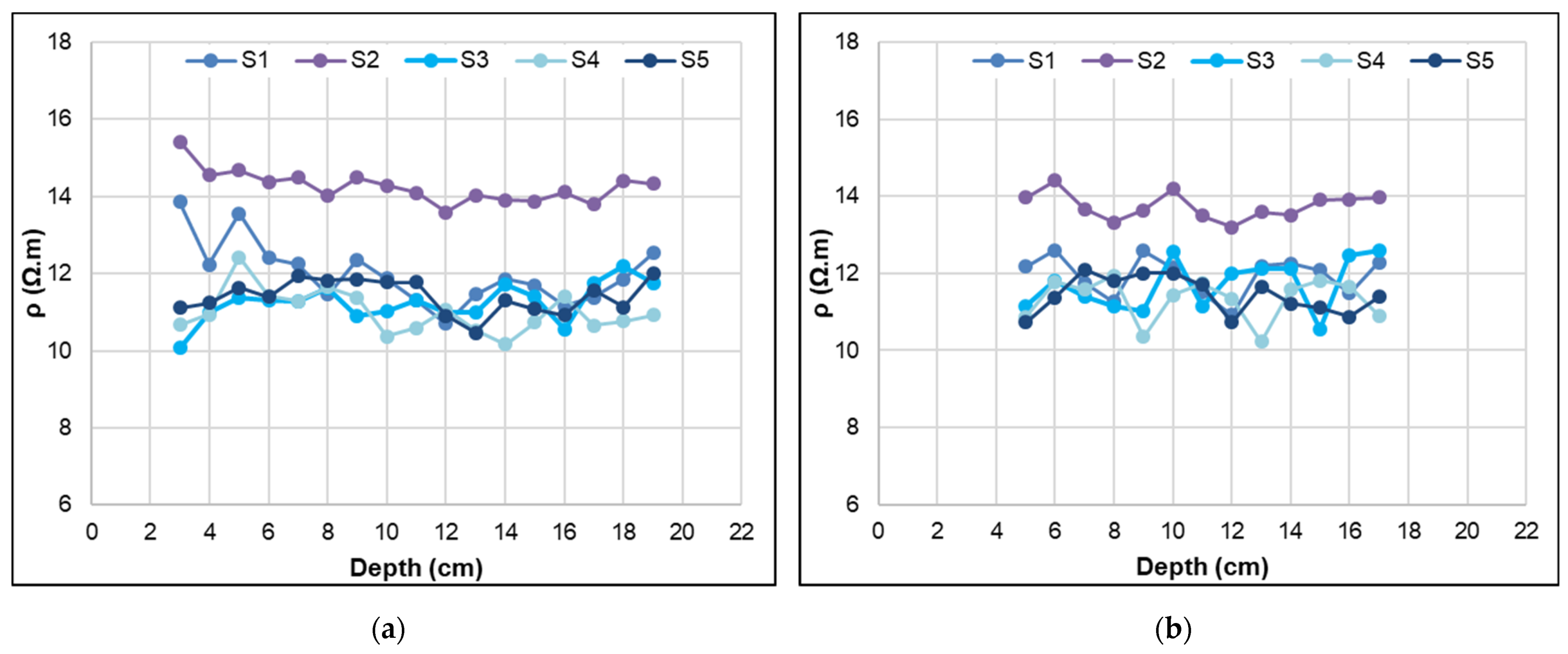
First, a study of repeatability and reproducibility of the resistivity measurements using the PCB sensors was carried out for specimens S1 to S5 in saturated conditions and at temperature T = 20 ± 2 °C. The coefficient of variation for repeatability ranged between 0.06% and 1.86% for resistivity measurements repeated three times. As for the reproducibility, which is associated with variability due to the sensor and concrete material among the five cylindrical specimens, the coefficient of variation of resistivity was equal to 4.6% for specimens S1, S3, S4, and S5 in the transmission configuration and 5.3% for the same four specimens in the Wenner configuration. This variation became higher when including specimen S2, where it reached 11.1% and 8.9% in the transmission and Wenner configurations, respectively. This might be explained by a difference in the material of specimen S2, possibly due to concrete casting or vibration. Figure 3 shows the resistivity profiles over depth using the transmission and Wenner configurations in nearly saturated conditions (Sr = 95.0 ± 2.0%) for all the specimens. Comparable values between the two measurement configurations are noted with 1.7% of variation, on average.
Second, a study of the variation of the resistivity profiles was carried out for all the specimens at different degrees of saturation (Sr = 72.2 ± 1.0%, 53.3 ± 0.3%, and 33.8 ± 0.5%) for both the transmission and Wenner configurations.
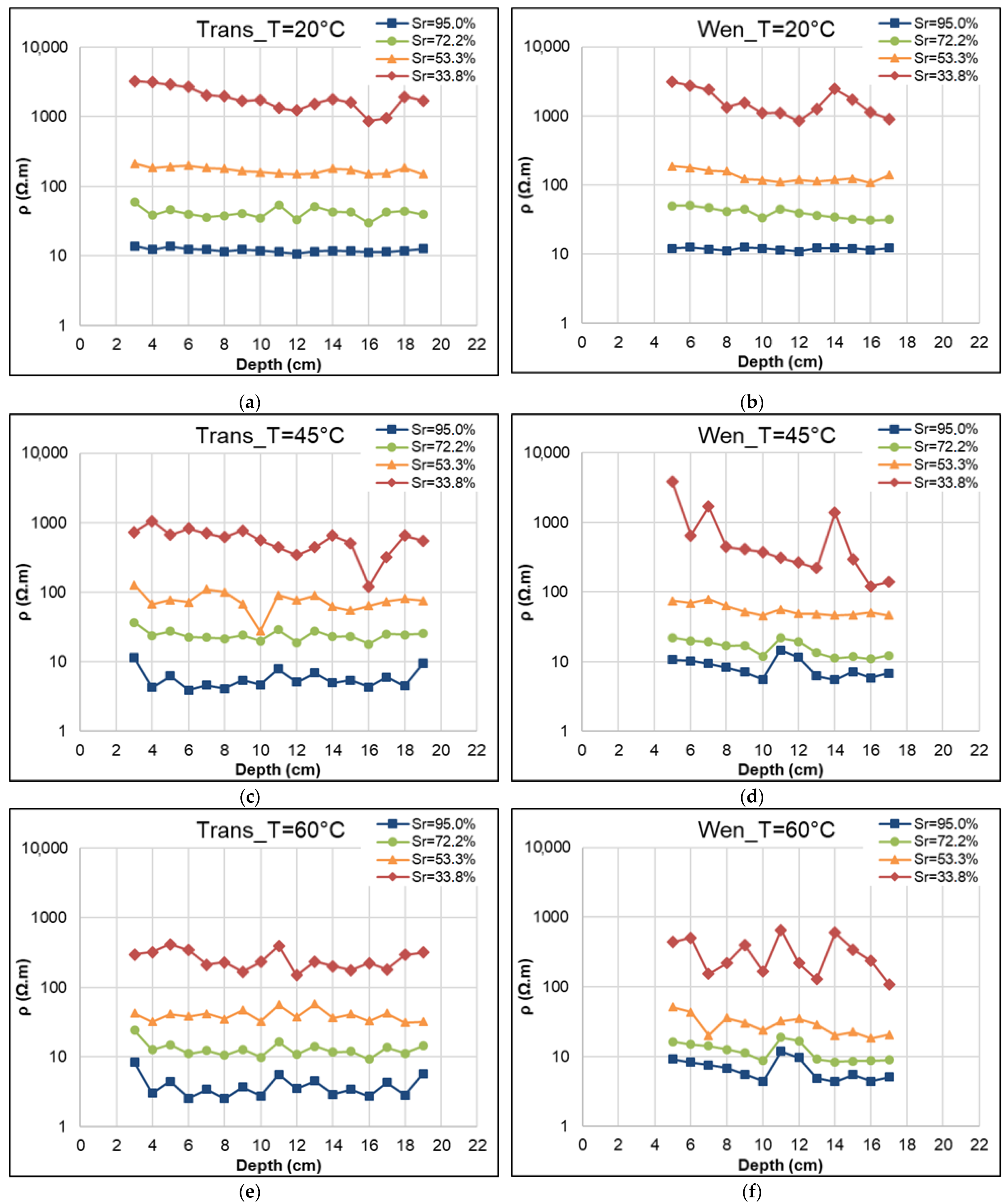
Figure 4 shows resistivity profiles over depth in the S1 specimen for the transmission and Wenner configurations at different temperatures T = 20, 45, and 60 °C, and at different degrees of saturation.
For all configurations and at each temperature, the resistivity obtained is higher at lower saturation degrees, which agrees with the results reported in the literature [39,40,41]. For a relatively dry concrete (Sr = 33.8 ± 0.5%), we obtained average resistivity values ranging between 1700 and 1900 Ω.m at T = 20 °C for the transmission and Wenner configurations. The maximum (3200 Ω.m) and minimum (870 Ω.m) resistivity values obtained here comply with the values reported in the literature for a dry concrete with CEM I cement between 1000 and 3000 Ω.m [21]. We note in Figure 4 that the specimen is less homogeneous at Sr = 33.8%, and that a larger variation in resistivity (high standard deviation) is observed over depth. This variation can be explained by the waiting time which was too short for the specimen (Ø11 × 22 cm) to be homogenized; an increase in the homogenization time, by doubling it, for example, might decrease the variation along the depth. Moreover, as degree of saturation decreased, resistivity values increased and measurements became more difficult to take because of increasing contact resistances between electrodes and concrete, thus generating greater variability in measurements. Furthermore, the connectivity of the liquid phase was no longer ensured at low degrees of saturation, which limited the flow of electrical current.
For each type of configuration at a fixed temperature and degree of saturation, the average resistivity over depth was calculated for each specimen. Then, to establish the calibration curves between resistivity and degree of saturation at each temperature, the average resistivity among all specimens was calculated for both configurations and for a fixed temperature and degree of saturation. The values of the average and the standard deviation of resistivity over all specimens, except S2, are presented in Table 2.
Figure 5 represents the calibration curves of resistivity vs. the degree of saturation at different temperatures presented separately for the transmission and Wenner configurations, based on the data shown in Table 2.
A power law regression was applied that yielded a coefficient of determination R2 greater than 0.961. The power trend (ρ = A.Sru) was consistent with Archie’s law [12]. In the range of the measured saturation degrees, we observed (Figure 5 and Table 1) that an increase in temperature led to a decrease in electrical resistivity. This result was consistent with many published results [21,22,35]. The correlation between the resistivity and the temperature is discussed in detail in the next section.

4. Discussion of the Temperature Influence on Resistivity

In this section, a comparison of the results for the temperature correction models is discussed.
To study the temperature effect on concrete resistivity, the behavior of resistivity depending on temperature was analyzed in the context of the Arrhenius law. Figure 6 represents the variation of the average resistivity as a function of temperature at four degrees of saturation, using the same average resistivities as previously used (all specimens except S2, see Table 1). It shows that the resistivity-versus-temperature relation follows a trend of exponential decay for both configurations, transmission and Wenner, and for all degrees of saturation. This is in accordance with the Arrhenius Equation (3) as well as with published results [35,40].
Equation (3) was used to calculate the activation energy for resistivity by regression analysis. The Arrhenius parameters shown in Table 3 were obtained by performing regressions on the data from Table 2 using Equation (3) [35,40]. An example of the regression analysis with the transmission configuration measurements for all specimens is shown in Table 3. The coefficients of determination (R2) vary between 0.89 and 0.94, indicating a good fit of the measured values to the Arrhenius law.
Table 3 shows that the value of Ea increases and the value of A decreases with decreasing values of Sr, as demonstrated in [31,36]. The Ea values range from 20 to 34 kJ/mol, which agree with the reported values [30,31,40]. Most of the reported methods employ fixed parameters, which causes either an overestimation or underestimation of the temperature effect. Our results clearly show that the value of the activation energy Ea was dependent on the saturation degree of the concrete and, therefore, on the concrete resistivity. Further investigation is necessary to study the relationship between the activation energy Ea, the nominal resistivity A, and the saturation degree Sr.
Using another approach, we considered a simplified linear resistivity-versus-temperature relationship within the measured temperature ranges [20–45 °C] and [45–60 °C]. Table 4 illustrates the percentage change in resistivity per °C at different degrees of saturation in both the transmission and Wenner configurations, assuming that the exponential relationship between the resistivity and the temperature is close to linear through the studied temperature intervals.
Table 4 shows that the percentage change in resistivity ranges from 1.3 to 3.8% per °C, which is partially in agreement with the values (1.8 to 3% or 3 to 5%) reported in the literature [19,21]. However, it also indicates that the percentage resistivity change depends on the saturation degree as well as on the temperature range. For a given temperature range, the resistivity change per °C is, in general, larger on concrete specimens with lower saturation degrees. For example, the percentage resistivity change per °C is 2.3%/°C for a water-saturated concrete in the temperature range of 45–60 °C, and 3.8% for concrete with the lowest degree of saturation (33.8%). This result agrees with [24] where it is reported that, for ordinary Portland cement (OPC) concrete, resistivity changes by 3% per °C at 21 °C for a 70% saturated concrete, whereas it changes by 5% per °C for a 30% saturation degree. With respect to temperature, the resistivity change per °C is larger at a higher temperature than at a lower temperature. For example, in nearly saturated conditions, the resistivity change per °C is 1.3% between 20 and 45 °C, and 2.3% between 45 and 60 °C. Note that the measurement dispersion increases with high resistivity values at low saturation degrees of concrete due to the presence of heterogeneities (e.g., coarse aggregates and air bubbles). Thus, high uncertainty can influence the percentage of change per degree, such as the value at 45 °C and S = 33.8%.

5. Conclusions

Temperature and saturation degree of the concrete structure highly influence its resistivity measurements. In this paper, experimental results on embedded PCB resistivity sensors are presented and compared to empirical models of temperature and saturation degree. The use of innovative embedded PCB sensors offers the possibility of evaluating the concrete resistivity along the structure’s depth as it is very important to evaluate the temperature contribution to the resistivity measurements for an accurate evaluation of water content in thick concrete structures. All measurements were performed under controlled conditions. Our experimental data behavior is highly consistent with well-established empirical models. Calibration curves that link the electrical resistivity with the degree of saturation at different temperatures (20, 45, and 60 °C) were established and shown to be consistent with Archie’s Law. The profiles of resistivity versus temperature were found to conform to Arrhenius’ law. Therefore, parameters for standardization of measurements to definite values of temperature and saturation degree were obtained for the studied concrete. More generally, this study clearly shows that standardization of measurements with inadequate parameter values could yield misleading results.
The main information obtained in this study concerns the function describing the evolution of resistivity versus saturation degree or temperature. The coefficients depend on the concrete mix. Thus, for new materials, we recommend a calibration that can be limited to very few adjustment points, which will save a lot of time while increasing the accuracy of the saturation degree evaluation attributed to resistivity at different temperatures.

Author Contributions

Conceptualization and methodology, all authors; experimentation, data collection, and analysis, J.B. and E.M.; writing—original draft preparation, J.B.; writing—review and editing, G.V., J.-P.B., S.P.L., Y.F. and B.Y. All authors have read and agreed to the published version of the manuscript.

Funding

This research was funded by Andra, Université Gustave Eiffel, and Université de Toulouse.

Institutional Review Board Statement

Not applicable.

Informed Consent Statement

Not applicable.

Data Availability Statement

The data presented in this study are available on request from the corresponding author.

Acknowledgments

The authors would like to thank Sylvie Lesoille, Xavier Bourbon, and Louis-Marie Cottineau for the enriching discussions and fruitful exchanges and for their contributions to this study.

Conflicts of Interest

The authors declare no conflict of interest.

References

  1. Baroghel-Bouny, V. Concrete Design for a Given Structure Service Life—Durability Management with Regard to Reinforcement Corrosion and Alkali-Silica Reaction—State of the Art and Guide for the Implementation of a Predictive Performance Approach Based upon Durability Indicators, (French version 2004); AFGC: Paris, France, 2007; 252p. [Google Scholar]
  2. Lawrence, C.D. Mortar Expansions Due to Delayed Ettringite Formation: Effects of Curing Period and Temperature. Cem. Concr. Res. 1995, 25, 903–914. [Google Scholar] [CrossRef]
  3. Malbois, M.; Nedjar, B.; Lavaud, S.; Rospars, C.; Divet, L.; Torrenti, J.-M. On DEF expansion modelling in concrete structures under variable hydric conditions. Constr. Build. Mater. 2019, 207, 396–402. [Google Scholar] [CrossRef]
  4. McCarter, W.J.; Chrisp, T.M.; Butler, A.; Basheer, P.A.M. Near–surface sensors for condition monitoring of cover-zone concrete. Constr. Build. Mater. 2001, 15, 115–124. [Google Scholar] [CrossRef]
  5. Sbartaï, Z.M.; Laurens, S.; Rhazi, J.; Balayssac, J.P.; Arliguie, G. Using radar direct wave for concrete condition assessment: Correlation with electrical resistivity. J. Appl. Geophys. 2007, 62, 361–374. [Google Scholar] [CrossRef]
  6. Minagawa, H.; Miyamoto, S.; Hisada, M. Relationship of Apparent Electrical Resistivity Measured by Four-Probe Method with Water Content Distribution in Concrete. J. Adv. Concr. Technol. 2017, 15, 278–289. [Google Scholar] [CrossRef]
  7. Du Plooy, R.; Villain, G.; Palma-Lopes, S.; Ihamouten, A.; Dérobert, X.; Thauvin, B. Electromagnetic non-destructive evaluation techniques for the monitoring of water and chloride ingress into concrete: A comparative study. Mater. Struct. 2015, 48, 369–386. [Google Scholar] [CrossRef]
  8. Balayssac, J.-P.; Garnier, V. (Eds.) Non-Destructive Testing and Evaluation of Civil Engineering Structures; Elsevier: Amsterdam, The Netherlands, 2017. [Google Scholar]
  9. Smyl, D. Electrical tomography for characterizing transport properties in cement-based materials: A review. Constr. Build. Mater. 2020, 244, 118299. [Google Scholar] [CrossRef]
  10. Larsen, C.K.; Sellevold, E.J.; Askeland, F.; Østvik, J.M.; Vennesland, O. Electrical resistivity of concrete part II: Influence of moisture content and temperature. In Proceedings of the 2nd International Symposium on Advances in Concrete through Science and Engineering, Quebec city, QC, Canada, 11–13 September 2006. [Google Scholar]
  11. Fares, M.; Villain, G.; Bonnet, S.; Palma-Lopes, S.; Thauvin, B.; Thiéry, M. Determining chloride content profiles in concrete using a resistivity probe. Cem. Concr. Compos. 2018, 94, 315–326. [Google Scholar] [CrossRef]
  12. Archie, G.E. The electrical resistivity log as an aid in determining some reservoir characteristics. Trans. Am. Inst. Min. Metall. Eng. 1942, 146, 54–62. [Google Scholar] [CrossRef]
  13. Lim, Y.-C.; Kim, T.; Hwang, C.-S. Modeling for apparent resistivity estimation along direction of electrode array above rebar in electrical resistivity measurement. J. Build. Eng. 2020, 31, 101417. [Google Scholar] [CrossRef]
  14. Polder, R.B. Test methods for on site measurement of resistivity of concrete—A RILEM TC-154 technical recommendation. Constr. Build. Mater. 2001, 15, 125–131. [Google Scholar] [CrossRef]
  15. Alhajj, M.A.; Palma-Lopes, S.; Villain, G. Accounting for steel rebar effect on resistivity profiles in view of reinforced concrete structure survey. Constr. Build. Mater. 2019, 223, 898–909. [Google Scholar] [CrossRef]
  16. Gowers, K.; Millard, S. Measurement of concrete resistivity for assessment of corrosion. ACI Mater. J. 1999, 96, 536–541. [Google Scholar]
  17. Bertolini, L.; Elsener, B.; Pedeferri, P.; Redaelli, E.; Polder, R. Corrosion of Steel in Concrete; Wiley: Weinheim, Germany, 2013. [Google Scholar]
  18. Rasch, E.; Willy Hinrichsen, F. Über eine Beziehung zwischen elektrischer Leitfähigkeit und Temperatur. Z. Für Elektrochem. Und Angew. Phys. Chem. 1908, 14, 41–46. [Google Scholar]
  19. Keller, G.V.; Frischknecht, F.C. Electrical Methods in Geophysical Prospecting; Pergamon: Oxford, UK, 1966. [Google Scholar]
  20. Castellote, M.; Alonso, M.C.; Andrade, C. Standardization, to a reference of 25 °C, of electrical resistivity for mortars and concretes in saturated or isolated conditions. ACI Mater. J. 2002, 99, 119–127. [Google Scholar]
  21. Polder, R.; Andrade, C.; Elsener, B.; Vennesland, Ø.; Gulikers, J.; Weidert, R.; Raupach, M. Test methods for on site measurement of resistivity of concrete. Mater. Struct. 2000, 33, 603–611. [Google Scholar] [CrossRef]
  22. Lataste, J.-F. Évaluation Non Destructive de L’état D’endommagement des Ouvrages en Béton Armé Par Mesures de Résistivité Electrique. Ph.D. Thesis, Université de Bordeaux 1, Bordeaux, France, 2002. [Google Scholar]
  23. Chataigner, S.; Saussol, J.-L.; Dérobert, X.; Villain, G.; Aubagnac, C. Temperature influence on electromagnetic measurements of concrete moisture. Eur. J. Environ. Civ. Eng. 2015, 19, 482–495. [Google Scholar] [CrossRef]
  24. Elkey, W.; Sellevold, E.J. Electrical Resistivity of Concrete; Norwegian Public Roads Administration Publication: Oslo, Norway, 1995; 33p. [Google Scholar]
  25. Hayley, K.; Bentley, L.R.; Gharibi, M.; Nightingale, M. Low temperature dependence of electrical resistivity: Implications for near surface geophysical monitoring. Geophys. Res. Lett. 2007, 34, L18402. [Google Scholar] [CrossRef]
  26. Badr, J.; Fargier, Y.; Palma-Lopes, S.; Deby, F.; Balayssac, J.-P.; Delepine-Lesoille, S.; Cottineau, L.-M.; Villain, G. Design and validation of a multi-electrode embedded sensor to monitor resistivity profiles over depth in concrete. Constr. Build. Mater. 2019, 223, 310–321. [Google Scholar] [CrossRef]
  27. Lecieux, Y.; Schoefs, F.; Bonnet, S.; Lecieux, T.; Palma-Lopes, S. Quantification and uncertainty analysis of a structural monitoring device: Detection of chloride in concrete using DC electrical resistivity measurement. Nondestruct. Test. Eval. 2015, 30, 216–232. [Google Scholar] [CrossRef]
  28. Villain, G.; Sbartaï, Z.M.; Lataste, J.-F.; Garnier, V.; Dérobert, X.; Abraham, O.; Bonnet, S.; Balayssac, J.-P.; Nguyen, N.T.; Fares, M. Characterization of water gradients in concrete by complementary NDT methods. In Proceedings of the International Symposium Non-Destructive Testing in Civil Engineering (NDT-CE 2015), Berlin, Germany, 15–17 September 2015. [Google Scholar]
  29. Bässler, R.; Mietz, J.; Raupach, M.; Klinghoffer, O. Corrosion Monitoring sensors for durability assessment of reinforced concrete structures. In Proceedings of the International Society for Optical Engineering (SPIE 2000), Newport Beach, CA, USA, 20–26 January 2000. [Google Scholar]
  30. McCarter, W.J.; Starrs, G.; Chrisp, T.M. Electrical conductivity, diffusion, and permeability of Portland cement-based mortars. Cem. Concr. Res. 2000, 30, 1395–1400. [Google Scholar] [CrossRef]
  31. Chrisp, T.M.; Starrs, G.; McCarter, W.J.; Rouchotas, E.; Blewett, J. Temperature-conductivity relationships for concrete: An activation energy approach. J. Mater. Sci. Lett. 2001, 20, 1085–1087. [Google Scholar] [CrossRef]
  32. Osterminski, K.; Schießl, P.; Volkwein, A.; Mayer, T.F. Modelling reinforcement corrosion–Usability of a factorial approach for modelling resistivity of concrete. Mater. Corros. 2006, 57, 926–931. [Google Scholar] [CrossRef]
  33. McCarter, W.J.; Taha, H.M.; Suryanto, B.; Starrs, G. Two-point concrete resistivity measurements: Interfacial phenomena at the electrode–concrete contact zone. Meas. Sci. Technol. 2015, 26, 085007. [Google Scholar] [CrossRef]
  34. Bockris, J.O.; Reddy, A.K.N. Volume 1: Modern Electrochemistry: Ionics, 2nd ed.; Springer: New York, NY, USA, 1998. [Google Scholar] [CrossRef]
  35. Liu, Y.; Presuel-Moreno, F.J. Normalization of Temperature Effect on Concrete Resistivity by Method Using Arrhenius Law (with Appendix). Mater. J. 2014, 111, 433–442. [Google Scholar] [CrossRef]
  36. Pour-Ghaz, M.; Isgor, O.B.; Ghods, P. The effect of temperature on the corrosion of steel in concrete. Part 1: Simulated polarization resistance tests and model development. Corros. Sci. 2009, 51, 415–425. [Google Scholar] [CrossRef]
  37. Parrott, L.J. Moisture conditioning and transport properties of concrete test specimens. Mater. Struct. 1994, 27, 460. [Google Scholar] [CrossRef]
  38. Villain, G.; Garnier, V.; Sbartaï, Z.M.; Derobert, X.; Balayssac, J.-P. Development of a calibration methodology to improve the on-site non-destructive evaluation of concrete durability indicators. Mater. Struct. 2018, 51, 40. [Google Scholar] [CrossRef]
  39. Hunkeler, F. The resistivity of pore water solution—a decisive parameter of rebar corrosion and repair methods. Constr. Build. Mater. 1996, 10, 381–389. [Google Scholar] [CrossRef]
  40. Villagrán Zaccardi, Y.A.; Fullea García, J.; Huélamo, P.; Di Maio, A.A. Influence of temperature and humidity on Portland cement mortar resistivity monitored with inner sensors. Mater. Corros. 2009, 60, 294–299. [Google Scholar] [CrossRef]
  41. Du Plooy, R.; Lopes, S.P.; Villain, G.; Dérobert, X. Development of a multi-ring resistivity cell and multi-electrode resistivity probe for investigation of cover concrete condition. NDT E Int. 2013, 54, 27–36. [Google Scholar] [CrossRef]
Figure 1. Schematic diagram of the PCB sensor with 19 electrodes (E1 to E19).
Applsci 12 09420 g001
Figure 2. View of a PCB sensor placed on the axis of a cylindrical mold designed to cast the concrete specimen.
Applsci 12 09420 g002
Figure 3. Resistivity profiles over depth in saturated conditions (Sr = 95.0 ± 2.0%) at temperature T = 20 ± 2 °C for all the specimens: (a) transmission configuration; (b) Wenner configuration [26].
Applsci 12 09420 g003
Figure 4. Resistivity profiles at different degrees of saturation for S1 specimen: (a) transmission configuration, T = 20 °C; (b) Wenner configuration, T = 20 °C; (c) transmission configuration, T = 45 °C; (d) Wenner configuration, T = 45 °C; (e) transmission configuration, T = 60 °C; (f) Wenner configuration, T = 60 °C.
Applsci 12 09420 g004
Figure 5. Calibration curves of resistivity* vs. degree of saturation at different temperatures: (a) transmission configuration; (b) Wenner configuration. * Resistivity data are averaged over all specimens except S2.
Applsci 12 09420 g005
Figure 6. Variation of the average concrete resistivity as a function of temperature at different degrees of saturation: (a) transmission configuration; (b) Wenner configuration.
Applsci 12 09420 g006
Table 1. Concrete mix design and characterization.
ConstituentsOriginQuantity (kg/m3)
Aggregates 4/12Boulonnais984
Sand 0/4 Boulonnais890
Cement CEM I 52.5 N Val d’Azergue350
Effective water (Weff) 206
Weff/C 0.59
Compressive strength at 28 days 42.6 + 1.3 MPa
Porosity accessible to water at 28 days 15.3 + 0.3%
Table 2. Electrical resistivity measured for all specimens, except S2, at different degrees of saturation in transmission and Wenner configurations at different temperatures (average ± standard deviation).
ρ (Ω.m) S r ( % ) 95.0 ± 2.0%72.2 ± 1.0%53.3 ± 0.3%33.8 ± 0.5%
T   ( ° C )
Transmission20 °C11.9 ± 1.340.1 ± 4.6175 ± 22.11906 ± 142
45 °C8.0 ± 0.626.5 ± 1.071.5 ± 7.2883 ± 279
60 °C5.3 ± 0.415.8 ± 2.442.4 ± 4.3379 ± 101
Wenner20 °C12.1 ± 1.142.5 ± 6.1140 ± 15.51710 ± 383
45 °C8.1 ± 1.917.7 ± 3.861.6 ± 9.2641 ± 145
60 °C5.7 ± 1.710.3 ± 2.631.8 ± 7.1303 ± 54
Table 3. Arrhenius law parameters fitted to the transmission configuration resistivity measurements on all specimens for each concrete degree of saturation.
S r   ( % ) A (Ω.m) E a   ( kJ / mol ) R2
95.0 ± 2.09.82 × 10−320.140.937
72.2 ± 1.09.25 × 10−320.400.890
53.3 ± 0.32.53 × 10−327.060.940
33.8 ± 0.51.74 × 10−333.540.942
Table 4. Percentage change in resistivity per °C at different degrees of saturation and in two separate ranges of temperature for the transmission and Wenner configurations.
Configuration S r ( % ) 95.0 ± 2.0%72.2 ± 1.0%53.3 ± 0.3%33.8 ± 0.5%
Δ T   ( ° C )
Transmission20–45 °C1.321.362.372.15
45–60 °C2.292.692.723.80
Wenner20–45 °C1.352.332.252.50
45–60 °C1.932.793.223.51
Publisher’s Note: MDPI stays neutral with regard to jurisdictional claims in published maps and institutional affiliations.