1. Introduction
Energy harvesting is a process that can help to recuperate energy that could be lost. Energy can be extracted from various sources, such as heat, mechanical vibration, etc. The piezoelectric energy harvesting is the most suitable to mechanical vibrations. The capacitance and electromechanical coefficients of the piezoelectric materials have defined the ability of the energy harvesting system. Energy harvesting system also depends on the device geometry and material properties. The mechanical strain is converted into electric potential is based on the stiffness and piezoelectrical material properties.
Erturk and Inman have theoretically and experimentally studied the bimorph beams of a piezoelectric cantilever for energy harvesting. The authors examined in depth the applications of piezoelectric materials in energy harvesting [
1]. Parinov et al. have presented a broad overview of various energy generation devices based on the use of piezoelectric elements in their design. This review presents results obtained in the field of piezoelectric energy harvesting over the past decade, including a wide range of experimental, analytical, and computer simulations. Piezoelectric transducers with electromechanical coupling and high power density compared to electromagnetic and electrostatic sensors have been widely used to obtain energy from various sources of vibrational energy [
2]. Comprehensive discussions have been carried out on the future perspective, last decade research analysis of microsystems, biomedical application, circuit designs, various designs and mechanisms, for piezoelectric energy harvesting [
3,
4,
5,
6,
7,
8,
9,
10]. The energy harvesting from nonlinear and broadband vibrations are capable from the devices [
11,
12]. Most approaches focus on carefully optimizing geometry to maximize the strain of piezoelectric material [
13]. Soloviev et al. have considered analytical modelling of a cantilever-type piezoelectric power generator. The authors discuss applied semi-analytical theories that make it possible to preliminarily estimate the output characteristics of piezoelectric generators of various configurations. The developed theories are based on Hamilton’s principle extended to the theory of electroelasticity. Within the framework of the Euler-Bernoulli hypotheses, a model of a cantilever-type piezoelectric generator with elements in the form of a bimorph is developed. The analytical calculations are compared with the FE calculation [
14]. The various piezoelectric materials and transducer configurations have been discussed by researchers. The operating parameters of various piezoelectric energy collection systems, as well as the scope of improvement of existing systems have been analysed. Individual examples of a push-type power generator, a stack-type generator, and a cantilever-type microgenerator have been considered. The piezoelectric materials have been used and the corresponding output power of such devices obtained [
15]. Perovskite (CTO)-based polymetric (PVDF) composite film as a piezoelectric energy harvester have been developed with biocompatibility. Sensor accuracy has been increased with the help of artificial neural networks and digital signal processing techniques. The output power density of 0.19 μW/cm
2 at 10
8 Ω was observed [
16]. Biomass as value-added material was utilized in the fabrication of piezoelectric nanogenerators and piezosupercapacitors for energy-oriented applications. The coconut husk-immobilized PVDF films were developed as piezoelectric films for the piezoelectric nanogenerator (PNG). The PNG has achieved a power density of 1.316 mW/cm
2 and an energy density of 76.33 mJ/cm
2 [
17].
Researchers have optimized various parameters such as length, width, thickness, and position of piezoelectric materials. Various types of piezoelectric materials are used for energy harvesting, namely PZT5H, PZT5A, PZT19, PVDF, MFC, etc. An axial-type piezoelectric energy generator with effective elements at the base of the generator have been presented. A finite element simulations have been carried out and generator operated at a frequency of 70 Hz and produced a voltage of 6 V [
18,
19,
20,
21]. The Gurtin-Murdoch model of surface stresses has been used to analyse nanoporous piezoelectric composites with stochastically scattered porosity using a cohesive approach to determine effective moduli [
22]. The properties of porous piezoelectric ceramics have been analysed using the effective moduli method at the pore boundaries, and numerical simulations of porous piezoelectric ceramics have been performed in ANSYS software [
23]. Kudimova et al. have solved the problem for piezoceramic matrix with metal inclusions and mixed pores to determine the effective properties [
24]. Nasedkin et al. have studied a numerical homogenization technique in piezocomposite system with metalized pores surfaces and developed random representative volume elements with random-size cubic inclusions [
25].
Researches have studied various connectivity for porous piezoelectric ceramics including 3–0, 3–1, 3–2, 3–3, 0–3, 1–3, 2–2, and 2–3. Where the first notation indicates the connectivity of the electromechanically active phase and the second number signifies the electromechanically passive phase [
26]. Porous ceramics are classified into two categories: (i) open cell (reticulated) and (ii) closed cell (foam). Pores are interconnected in open cell ceramics, whereas pores are generally isolated in a continuous ceramic matrix in a closed cell. Porous piezoelectric ceramics are composite materials made of two phases: (i) a porous (passive) phase and (ii) a piezoelectric cell (active) phase. The piezoelectric active phase forms a three-dimensional matrix, in which the passive phase exists in the form of isolated (0–3 connectivity) and/or interconnected inclusions (3–3 connectivity).
In this work, the axial-type piezoelectric energy harvester is designed in such a way that (i) the piezoelectric bimorph (d31) is deformed by the duralumin base plate, (ii) the piezoelectric cylinders (d33) are compressed by the L-shaped steel beam, and (iii) various proof mass position can be used for the different eigenvalues and can be located in the duralumin base plate due to the design flexibilities above with various mechanical vibration inputs. The piezoelectric energy harvester is capable to energy harvesting. In this paper, finite element modelling and experimental analyses of axial-type piezoelectric energy harvester are carried out and compared. The various porous piezoelectric materials are used for energy harvesting in the case of axial loading conditions and base excitation. The effect of various porosities in the energy harvesting system under harmonic base excitation is analysed. The effects of the porosities in bimorphs and cylinders are analysed individually with a combined effect onto the harvester by using numerical simulations. The output voltage and power are calculated for various piezoelectric porosities, electric resistances and proof mass positions. The effects of accelerations and porosities are also analysed.
2. Modelling of Porous Piezoelectric Based Energy Harvester
There are two types of composites that can give precise solutions: (i) serial circuit (
εs) and, (ii) parallel circuit (
εP). In the serial circuit, the phase boundary runs normally in the direction of the applied field and, in the parallel circuit, the boundaries between adjacent phases are parallel to the direction of the applied field [
26,
27]:
The effective permittivity ε* must be calculated from the permittivities ε′ and ε″ of two components and their volume fractions ν′ and ν″ = 1 − ν′.
The main purpose of this work is to study and analyse the output parameters of the piezoelectric energy generator. A piezoelectric energy harvesting device is a composite elastic and electroelastic body. The piezoelectric ceramics are made with various effective modules. The device is assumed to have small elastic oscillations in the moving coordinate system [
28,
29,
30]. The mathematical model of piezoelectric energy generator devices can be presented, based on the initial boundary value problem of linear electric elasticity theory [
31]:
The mathematical formulation for the elastic medium:
The mathematical formulation for piezoelectric materials is written as
where
is the material density;
are the displacement vector components;
are the stress tensor components;
are the density vector components;
are the electric induction vector components;
are the elastic moduli components of fourth rank tensor;
are the piezoelectric coefficients components of third rank tensor;
are the strain tensor components;
are the electric field vector components;
are the electric potential vector components;
are the dielectric constants tensor components;
are the non-negative damping coefficients (the value of ζd is used in ANSYS software).
Since harmonic analysis is used in the calculations, the following operations are performed for the corresponding components in the equations:
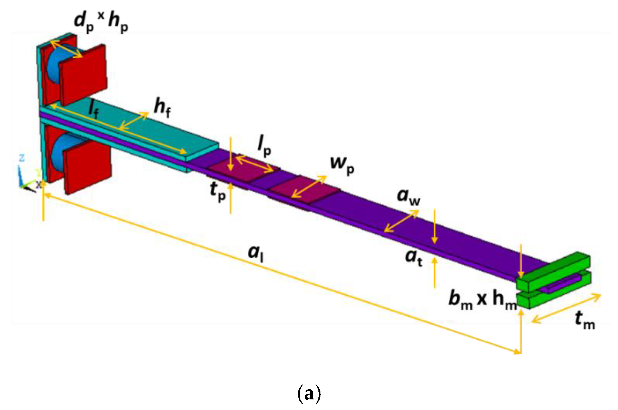
The axial piezoelectric generator model includes two piezoelectric cylinders, two piezoelectric bimorphs, duralumin substrates, proof mass, and L-shaped steel plates. The end of the piezo cylinder is fixed to the L-shaped steel plate, while the other end is fixed by a rigid pinch. The L-shaped steel plate and the duralumin substrate are glued together. The proof mass is fixed near the fixed end of the duralumin substrate. The two piezo-bimorphs are fixed near to L-shaped steel plate in the duralumin substrate as shown in
Figure 1. The dimension characteristics of the elements of the piezoelectric energy generators are listed in
Table 1. The material properties are summarized in
Table 2. The porous piezoelectric ceramic materials are analysed by various researchers at different connectivity [
32,
33]. Various authors have designed and manufactured the piezoceramic with various porosities. In this work, porous piezoelectric materials from
Table 3 with 0% porosity are used as the basic piezoelectric material.
Table 3 specifies the characteristics of the representative volumes of 3–0 connectivity type without additional restrictions on the location of the particles. The calculation of the actual properties of porous composite materials is given in the range of 10–80 % porosity [
34].
3. Experimental Setup
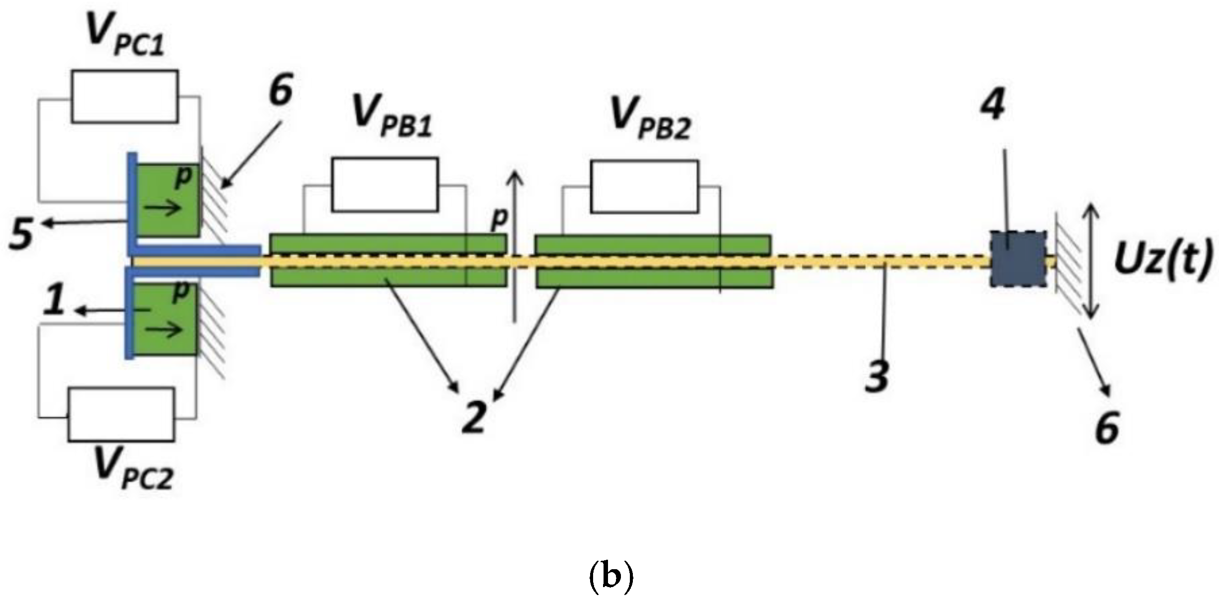
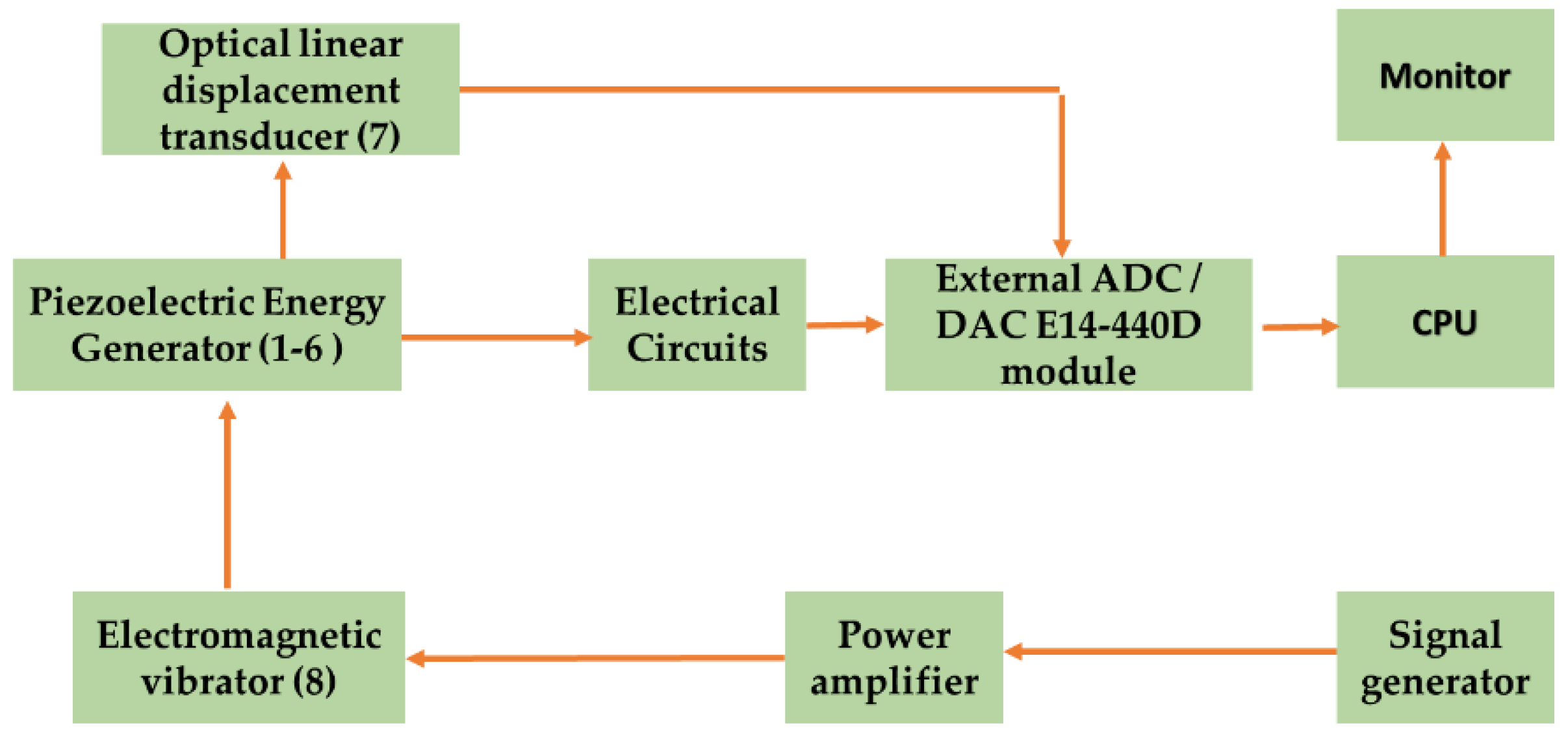
The schematic diagram of the experimental setup is shown in
Figure 2 and the experimental setup is present in
Figure 3. The electric power is supplied to the electromagnetic vibrator by using signal generator through power amplifier. The piezoelectric energy harvesting device is mounted on the electromagnetic vibrator. When an electromagnetic vibrator works, it vibrates the duralumin base plate and L-shaped steel plates. The piezoelectric bimorph (
d31) and cylinders (
d33) are mounted on the duralumin base plate and the L-shaped steel plate, respectively. Due to vibration, alternating deformations tension-compression in plates (2), and compression-tension in cylinders (1) occurred due to the reaction of the fixed supports. The displacement of the duralumin base plate is measured by the optical linear displacement transducer. The output voltage of the piezoelectric bimorphs and cylinders is collected by the electric circuit. The displacement and voltage signals are transmitted to the CPU via an external ADC/DAC E14-440D module. Power graph software is used for signal processing and measuring the output signals. The technical configurations of the measuring devices are used:
- (i)
the frequency range is 1–1000 Hz for force oscillations;
- (ii)
a range from 0 to 5 mm is measurable for lateral displacements of the device;
- (iii)
the input electric voltage is 0.1–10 V for the electromagnetic oscillations exciter;
- (iv)
the sensitivity is not less than 5 µm of the optical displacement sensor.
The direct piezoelectric effect acts on the cylinders (d33) as well as bimorphs (d31). The combined use of these elements allows increasing the output power and conversion efficiency of the converter. When these elements are combined, the converter’s output power and conversion efficiency can be increased. The output voltage of the piezoelectric bimorphs and cylinders is called the total cumulative voltage output. All the piezoelectric elements are connected in series.
4. Finite Element Modelling of the Energy Harvesting Device
The finite element is an auspicious and powerful method for modelling porous ceramics. Researchers, using FEA software to analyse piezoceramic models, have established the relations between numerical, mathematical, and experimental analysis. These relations do not only provide a satisfactory description and forecast of the properties of porous piezoelectric ceramics and devices. The effective moduli method is used using ANSYS software for analysing the effective constants of porous piezoelectric ceramics [
23,
24,
32].
A porous piezoelectric energy device is shown in
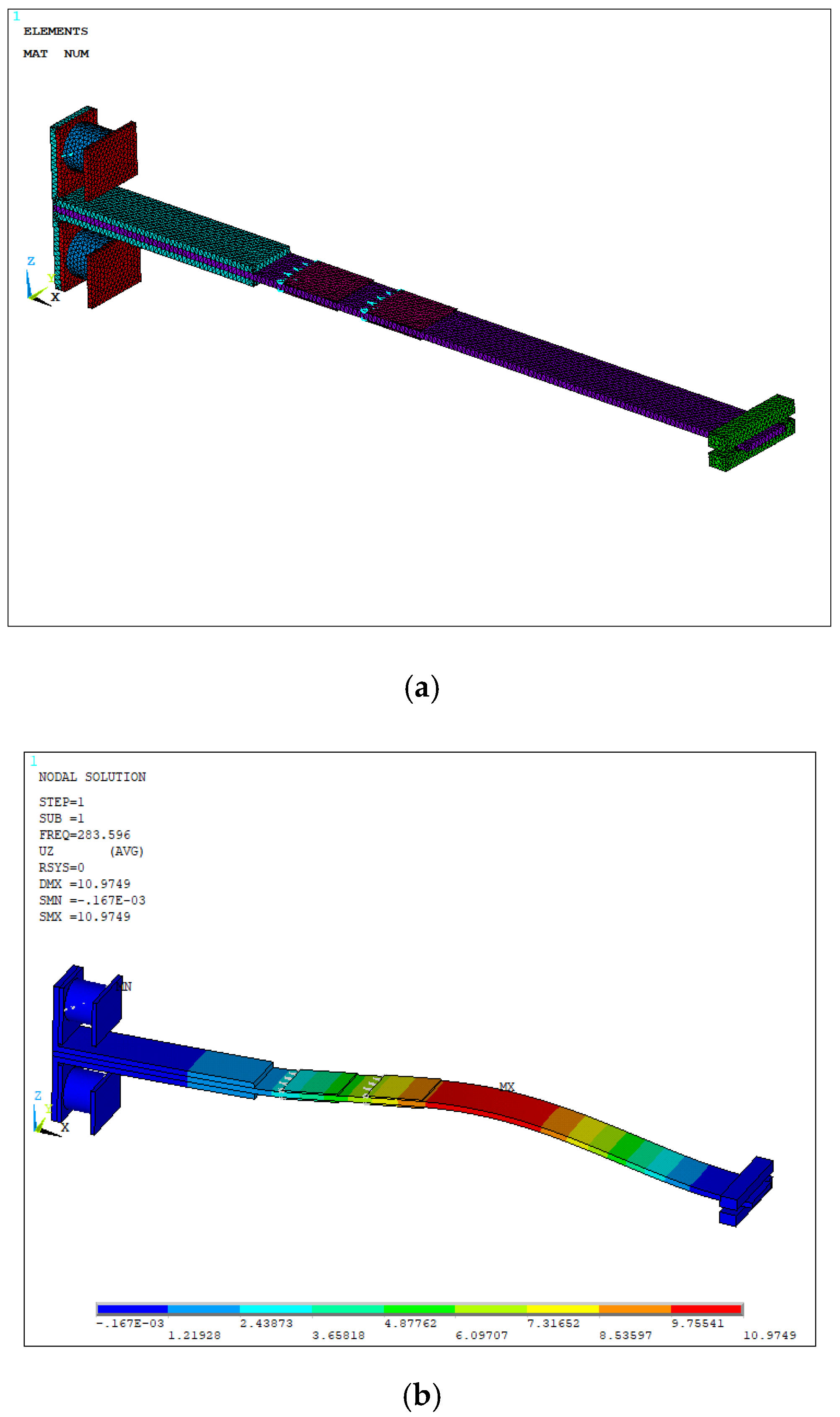
Figure 1. A finite element model is created using the ANSYS software. SOLID226 elements are used for various porous piezoelectric cylinders and piezoelectric bimorphs. The element CIRCU94 is used for the electric analysis. The SOLID186 elements are used to mesh all remaining materials considered in the device. The finite element model of the piezoelectric energy generator is shown in
Figure 4a. The mesh independency tests are carried out for all porous piezoelectric energy harvesting devices and, 46,123 elements are created.
Figure 4b shows the mode shape at the first-eigen frequency of 283.59 Hz.
5. Analysis of Results and Discussion
In this work, the piezoelectric energy generator is classified into two categories: (i) passive domain and, (ii) active domain. The passive domain consists of a duralumin base plate, L-shaped steel plate and, proof mass. The active domain consists of porous piezoelectric bimorphs and cylinders. The research work is focused into the effect of the various piezoelectric porosities on the energy harvesting. The numerical simulations are carried out for various porosities from 0 to 80%. Analysis is focused on the effect of piezoelectric bimorphs, piezoelectric cylinders, and combined effects in energy harvesting. Investigations of oscillations are carried out at various piezoelectric porosities of axial-type energy generators under harmonic loading. The harmonic and modal analysis is carried out under the applied uniform acceleration of 5 m/s2 for all structural units.
5.1. Result Validation
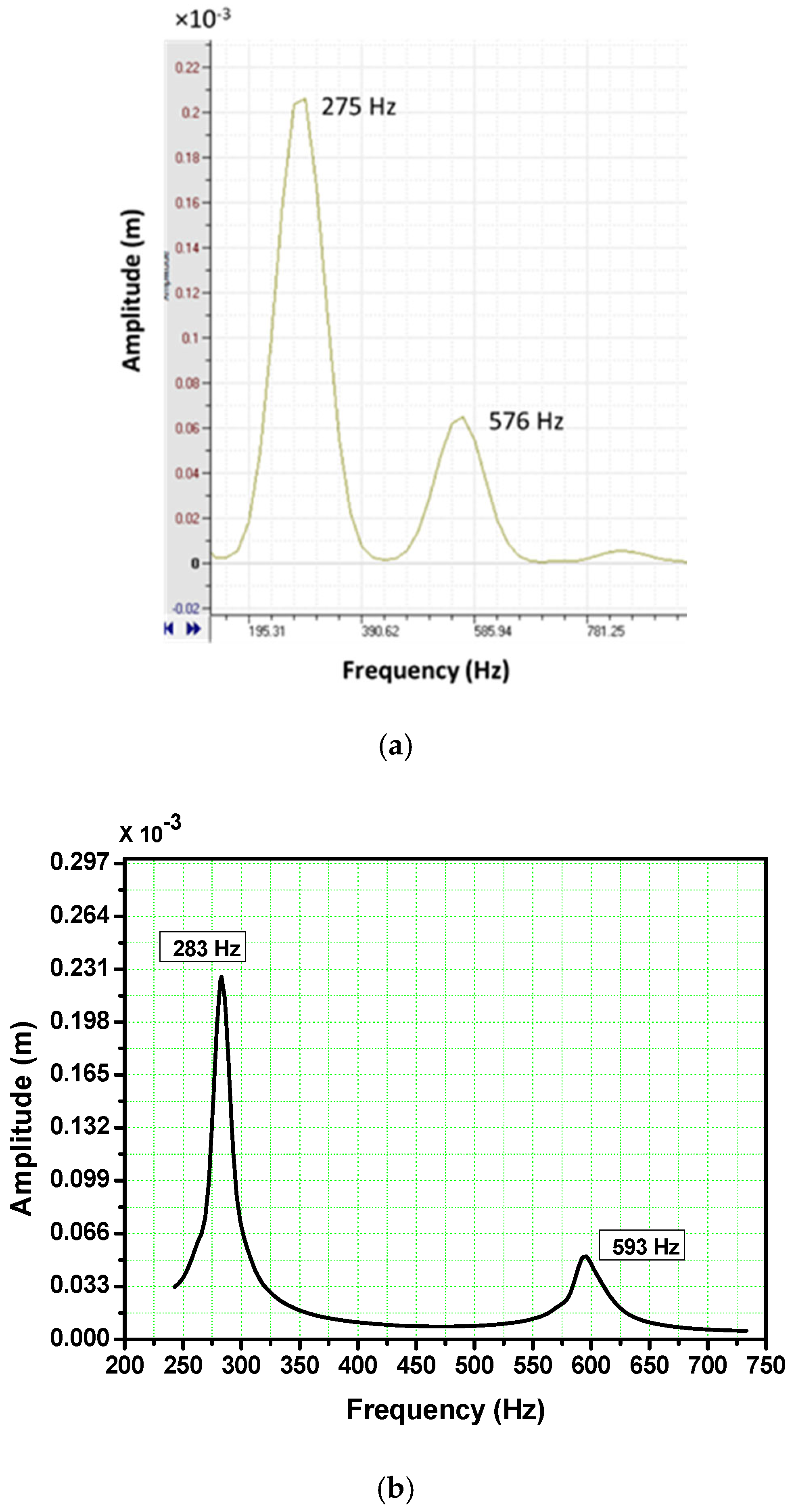
Numerical simulations of the piezoelectric energy generator are carried out by ANSYS software. The modal and harmonic simulations are studied and analysed. The first and second eigen-frequencies are 283 Hz and 593 Hz, respectively. The output deflection amplitudes at both the eigen-frequencies are summarised in
Table 4. The experimental results are obtained and evaluated for the piezoelectric energy generator. The first and second eigen-frequencies are 275 Hz and, 576 Hz, respectively. The comparisons of numerical simulations and experimental results are shown in
Figure 5 and summarized in
Table 4. The analysis of the comparisons shows an acceptable coincidence of the results.
5.2. Effect of Porosity in the Energy Harvesting Device
The porous piezoelectric energy harvesting device is numerically examined by varying the porosities from 0 to 80%. The
d31 piezoelectric power generator is more suitable for small forces and low vibration levels, at the same time, the
d33-type is most suitable for high-force vibrations. In the device, two piezoelectric bimorphs (
d31) and two cylinders (
d33) are used for the analysis. The poling of the bimorphs and cylinders are
d31 and
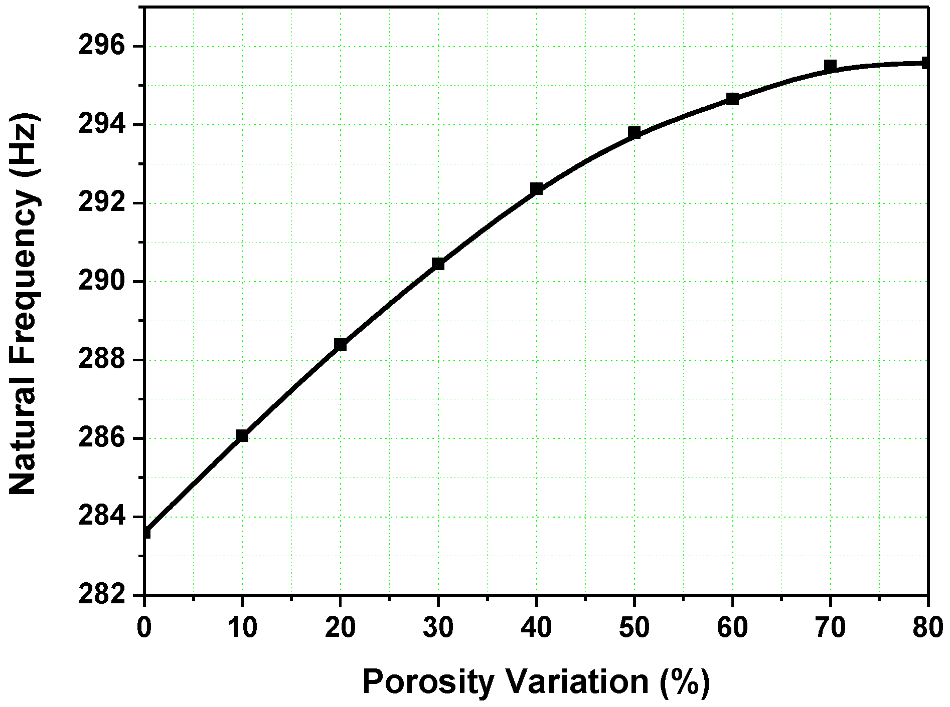
d33, respectively. The first eigenvalue of the device is increased when the porosities of the piezoelectric bimorphs and cylinders increase. The first eigenvalue is 283 Hz and 295 Hz in cases of 0% and 80% porosity, respectively, as shown in
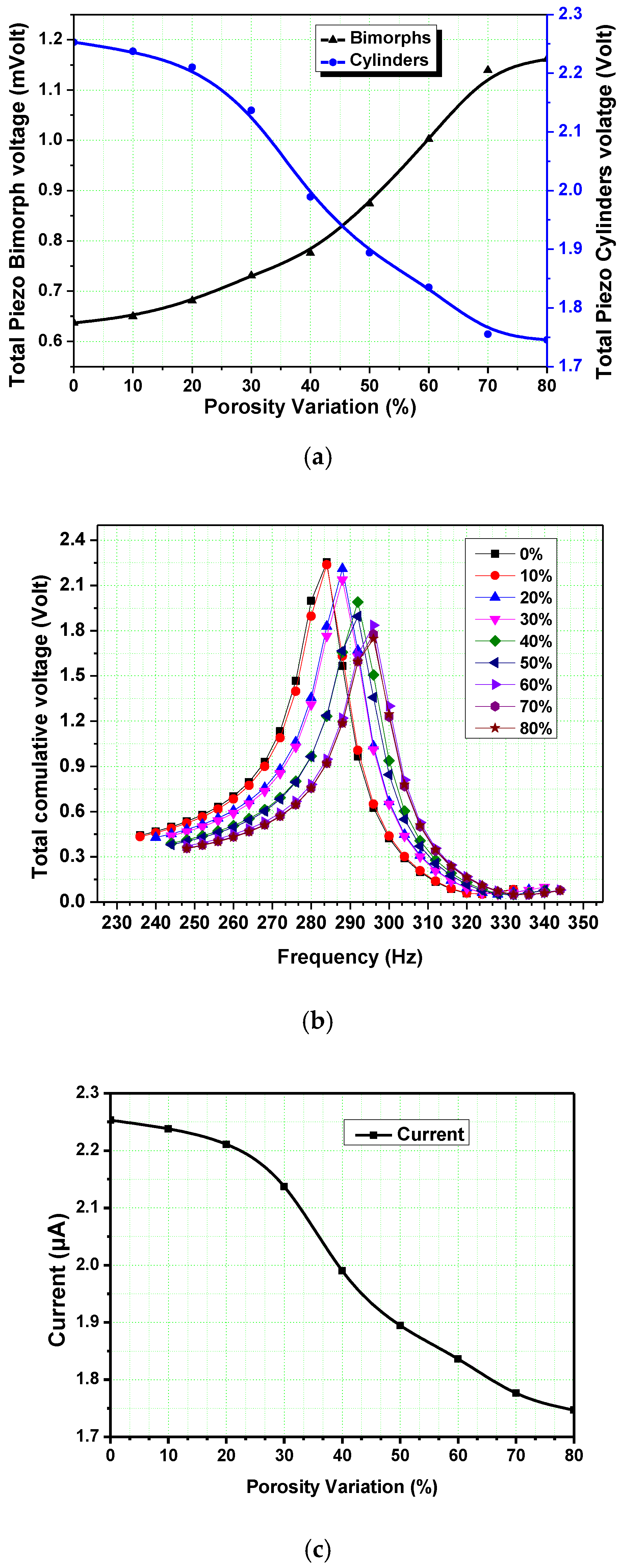
Figure 6. The output voltage of the piezoelectric bimorphs increases when the porosity increases. The output voltage decreases when the porosity of the piezoelectric cylinder increases as shown in
Figure 7a. The total cumulative voltage of the energy harvesting device decreases, when the porosities of piezoelectric materials increase. The output voltages measured are equal to 2.25 V and 1.75 V for 0% and 80% porosities, respectively, see
Figure 7b. The measured values of output current are equal to 2.53 µA and 1.74 µA in the cases of 0% and 80% porosity, respectively. The current intensity decreases with increasing the porosity as shown in
Figure 7c.
The numerical simulations are carried out for all the analysis. In the numerical simulation, all parameters and boundary conditions (i.e., damping factor, piezo capacitance, etc.) are established as per the fabricated model. For the case of energy harvesting of the piezoelectric energy harvester, the electrical output power delivered to the resistive load is measured by the equation: P = V2/R, where R is the resistive load and, V is the voltage across the resistive load.
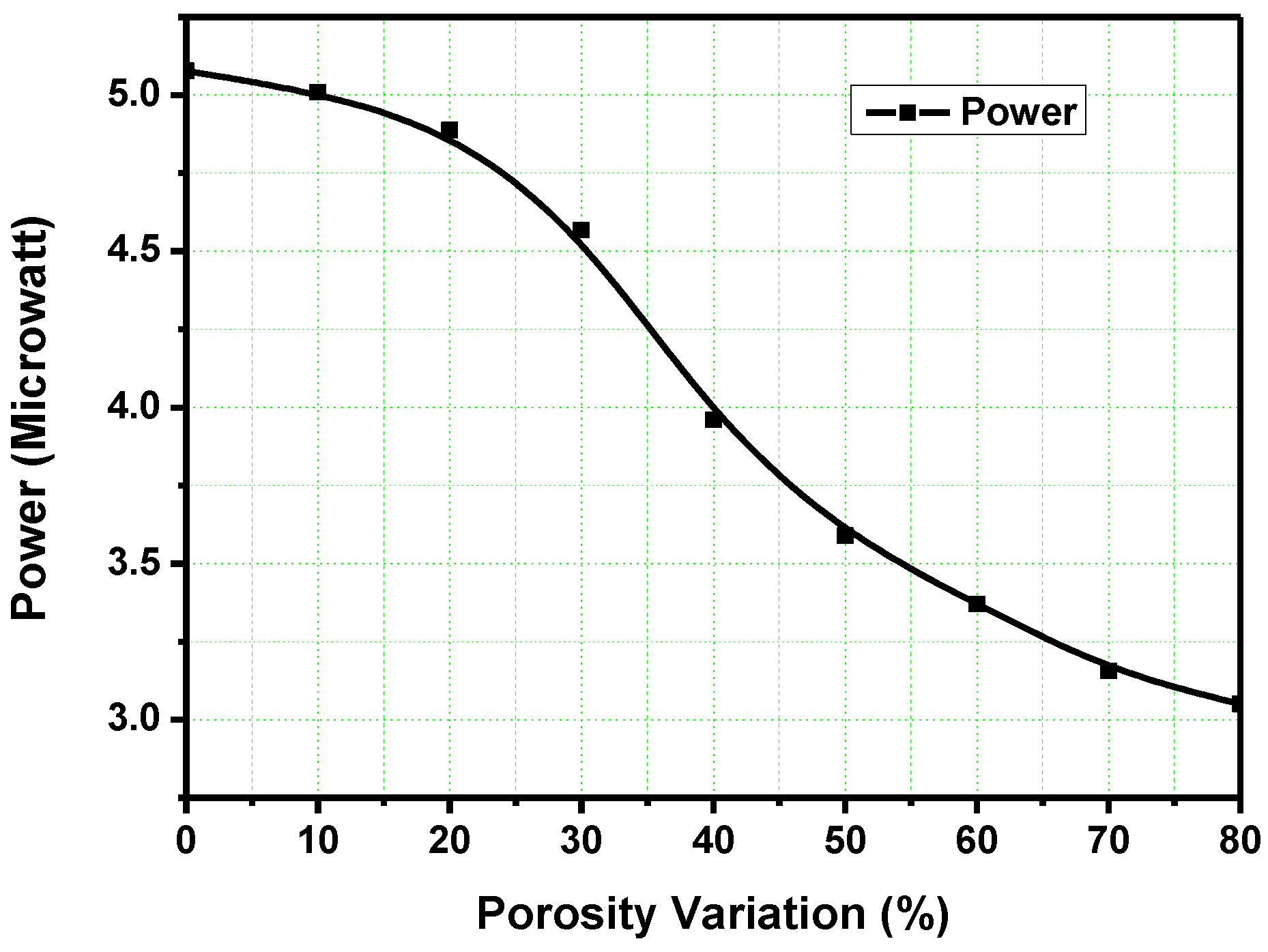
The maximum and minimum powers of 5.1 µW and 3.0 µW, respectively, are obtained from the device as shown in
Figure 8. When the porosity increases, the output power decreases. From
Figure 7a, porosity increases the
d31 sensitivity of the piezoelectric patches but in the case of
d33 sensitivity, it is decreased. Porous piezoelectric ceramics can be used in a variety of applications such as underwater acoustics, non-destructive testing, medical ultrasonic devices, etc. due to their high sensitivity.
5.3. Effect of Porosity with Various Position of Proof Mass
The effects of the various proof mass positions and piezoelectric porosities are analysed. The proof mass is attached at various positions from 160 mm to 250 mm from the piezocylinder end. The maximum output voltage is obtained at 250 mm of proof mass position. The minimum voltage is obtained at 190 mm proof mass position. The proof mass is attached at near centre of the duralumin base plate, the deflection is minimum due to restriction by the proof mass. By increasing the distance of the proof mass from 190 mm, the deflection increases as shown in
Figure 9.
5.4. Effect of Load Resistance
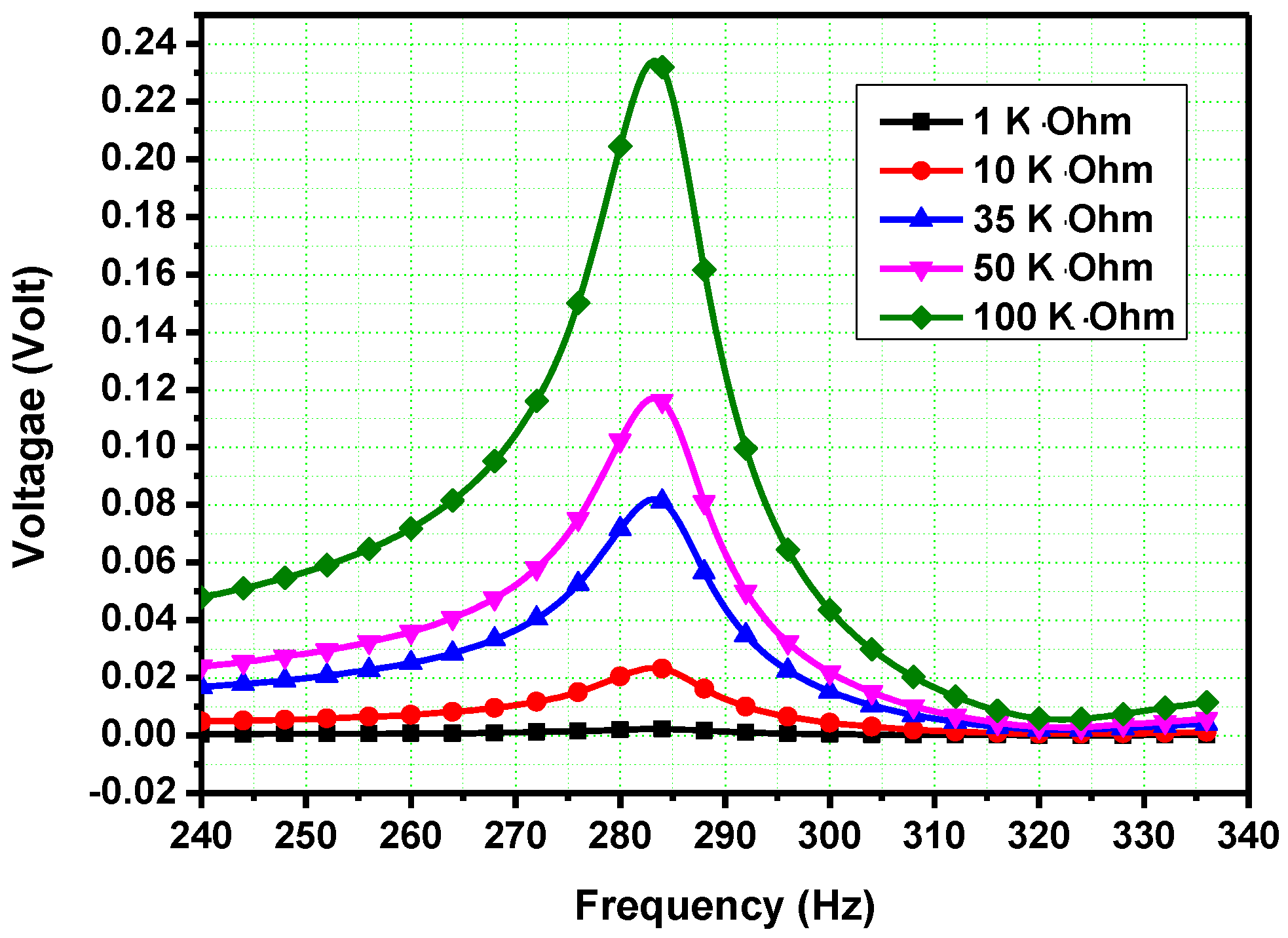
The effect of the load resistance is analysed, when the proof mass is attached at 250 mm distance from piezo cylinder end. The first eigen-value remains the same and total output voltage increases when the resistance increases as shown in
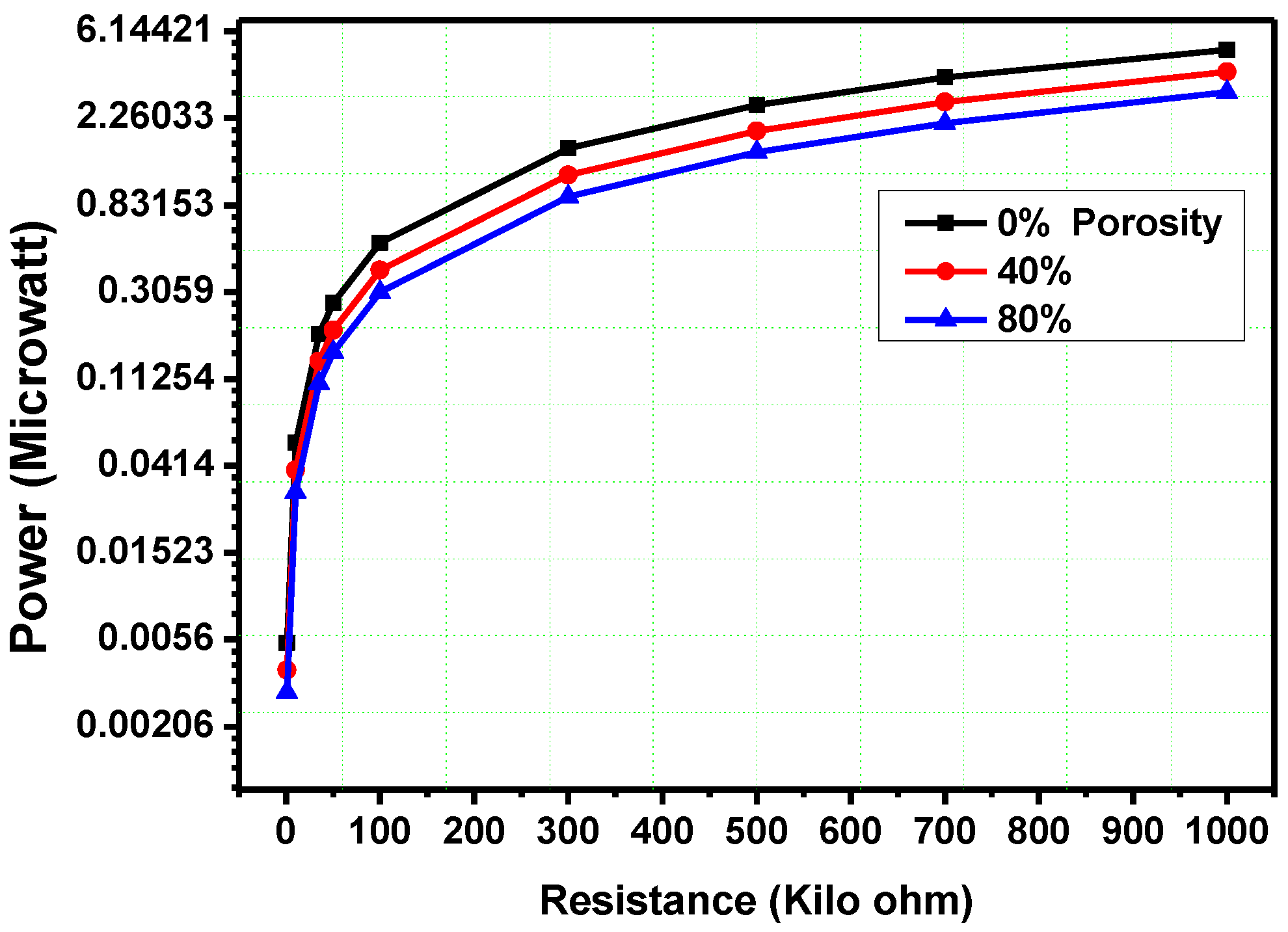
Figure 10. The effect of the various porosities at different resistances is analysed. When porosity increases, the output voltage decreases. The output power decreases when porosity increases and the output power increases when resistance increases. From 1 KΩ to 300 KΩ resistance, the output power increases rapidly but above 700 KΩ resistance, the output power increases slowly and tends to constant value as shown in
Figure 11.
5.5. Effect of the Acceleration in the Energy Harvesting Device
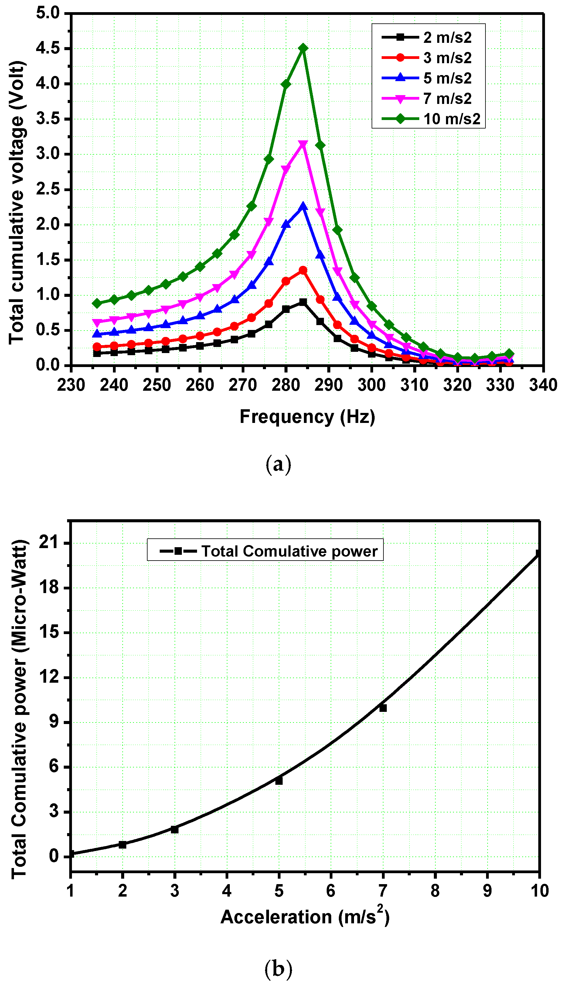
The values of applied vibration accelerations are varied from 1 m⋅s
−2 to 10 m⋅s
−2. When acceleration increases, the output voltage of the bimorphs and cylinders increases, too. The total cumulative voltage (see,
Figure 12a) and power (see,
Figure 12b) increase, when the applied acceleration increases. The maximum voltage and power are equal to 4.5 V and 21 µW, respectively, at 10 m⋅s
−2 acceleration.
6. Conclusions
In this study, an axial-type porous piezoelectric energy generator is designed and investigated. The experimental and numerical simulations are carried out for different operating conditions. The errors of 2.83% and 9.2% are obtained at the first eigen-frequency and deflection amplitude, respectively, for the experimental and numerical simulations. In the case of increasing the porosity, output voltage increases in bimorph patches and decreases in cylinders. The output voltages measured are equal to 2.25 V and 1.75 V for 0% and 80% porosities, respectively. The measured values of output current are equal to 2.53 µA and 1.74 µA in the cases of 0% and 80% porosity, respectively. The current intensity decreases with increasing the porosity However, the total cumulative voltage and power decrease. The maximum and minimum powers of 5.1 µW and 3.0 µW, respectively, are obtained from the device. From 1 KΩ to 300 KΩ resistance, the output power increases rapidly but above 700 KΩ resistance, the output power increases slowly and tends to constant value. When applied vibration acceleration increases, the output voltage of the bimorphs and cylinders increases, too. The total cumulative voltage and power increase, when the applied acceleration increases. The maximum voltage and power are equal to 4.5 V and 21 µW, respectively, at 10 m⋅s−2 acceleration. The inner structure of the porous polymer does not change, and the mechanical strength of the porous piezoceramic is relatively low. Porosity increases the d31 sensitivity of the piezoelectric patches.
Author Contributions
R.K.H.: software, original draft preparation, review and editing, setting up experimental work, methodology. A.V.C.: review and editing, setting up experimental work, production of calculations and conclusions, validation of research methods. I.A.P.: supervision, validation of research methods funding acquisition, resources, formal analysis. V.E.Y.: production of calculations and conclusions, formal analysis. All authors have read and agreed to the published version of the manuscript.
Funding
This research was funded by the grant from the Ministry of Science and Higher Education of Russia supported by Southern Federal University, grant No. VnGr-07/2020-04-IM.
Institutional Review Board Statement
Not applicable.
Informed Consent Statement
Not applicable.
Data Availability Statement
Not applicable.
Conflicts of Interest
The authors declare no conflict of interest.
References
- Erturk, A.; Inman, D.J. Piezoelectric Energy Harvesting; John Wiley & Sons: Hoboken, NJ, USA, 2011; ISBN 9780470682548. [Google Scholar]
- Parinov, I.A.; Cherpakov, A. V Overview: State-of-the-Art in the Energy Harvesting Based on Piezoelectric Devices for Last Decade. Symmetry 2022, 14, 765. [Google Scholar] [CrossRef]
- Beeby, S.P.; Tudor, M.J.; White, N.M. Energy harvesting vibration sources for microsystems applications. Meas. Sci. Technol. 2006, 17, R175–R195. [Google Scholar] [CrossRef]
- Yang, Z.; Zhou, S.; Zu, J.; Inman, D. High-Performance Piezoelectric Energy Harvesters and Their Applications. Joule 2018, 2, 642–697. [Google Scholar] [CrossRef]
- Lee, B.S.; Lin, S.C.; Wu, W.J.; Wang, X.Y.; Chang, P.Z.; Lee, C.K. Piezoelectric MEMS generators fabricated with an aerosol deposition PZT thin film. J. Micromechanics Microengineering 2009, 19, 065014. [Google Scholar] [CrossRef]
- Gao, X.; Yang, J.; Wu, J.; Xin, X.; Li, Z.; Yuan, X.; Shen, X.; Dong, S. Piezoelectric Actuators and Motors: Materials, Designs, and Applications. Adv. Mater. Technol. 2020, 5, 1900716. [Google Scholar] [CrossRef]
- Martínez-Ayuso, G.; Friswell, M.I.; Haddad Khodaparast, H.; Roscow, J.I.; Bowen, C.R. Electric field distribution in porous piezoelectric materials during polarization. Acta Mater. 2019, 173, 332–341. [Google Scholar] [CrossRef]
- Sharma, S.; Kiran, R.; Azad, P.; Vaish, R. A review of piezoelectric energy harvesting tiles: Available designs and future perspective. Energy Convers. Manag. 2022, 254, 115272. [Google Scholar] [CrossRef]
- Khalili, M.; Ahmed, S.; Papagiannakis, A.T. Piezoelectric energy harvesting for powering a novel weigh-in-motion system. Energy Convers. Manag. X 2022, 15, 100259. [Google Scholar] [CrossRef]
- Maurya, D.; Yan, Y.; Priya, S. Piezoelectric Materials for Energy Harvesting; CRC Press: Boca Raton, FL, USA, 2015; pp. 143–178. [Google Scholar] [CrossRef]
- Ascione, A.; Gherlone, M.; Orifici, A.C. Nonlinear static analysis of composite beams with piezoelectric actuator patches using the Refined Zigzag Theory. Compos. Struct. 2022, 282, 115018. [Google Scholar] [CrossRef]
- Chand, R.R.; Tyagi, A. Investigation of the Effects of the Piezoelectric Patch Thickness and Tapering on the Nonlinearity of a Parabolic Converging Width Vibration Energy Harvester. J. Vib. Eng. Technol. 2022, 10, 1–18. [Google Scholar] [CrossRef]
- Haldkar, R.K.; Cherpakov, A.V.; Parinov, I.A. Modeling, analysis and design optimizations of an axial-type piezoelectric energy generator for optimal output. Smart Mater. Struct. 2022, 31, 65019. [Google Scholar] [CrossRef]
- Soloviev, A.N.; Chebanenko, V.A.; Parinov, I.A. Mathematical modelling of piezoelectric generators on the base of the Kantorovich method. In Analysis and Modelling of Advanced Structures and Smart Systems; Springer: Singapore, 2018; Volume 81, ISBN 9789811068959. [Google Scholar]
- Parinov, I.A.; Chang, S.H.; Yun-Hae, K.; Nao-Aki, N. Physics and Mechanics of New Materials and Their Applications; Springer Nature Switzerland AG: Cham, Switzerland, 2021; ISBN 9781626185357. [Google Scholar]
- Panda, S.; Hajra, S.; Jeong, H.; Panigrahi, B.K.; Pakawanit, P.; Dubal, D.; Hong, S.; Kim, H.J. Biocompatible CaTiO3-PVDF composite-based piezoelectric nanogenerator for exercise evaluation and energy harvesting. Nano Energy 2022, 102, 107682. [Google Scholar] [CrossRef]
- Sahu, M.; Hajra, S.; Jadhav, S.; Panigrahi, B.K.; Dubal, D.; Kim, H.J. Bio-waste composites for cost-effective self-powered breathing patterns monitoring: An insight into energy harvesting and storage properties. Sustain. Mater. Technol. 2022, 32, e00396. [Google Scholar] [CrossRef]
- Khalatkar, A.; Gupta, V.K.; Haldkar, R. Modeling and simulation of cantilever beam for optimal placement of piezoelectric actuators for maximum energy harvesting. Smart Nano-Micro Mater. Devices 2011, 8204, 82042G. [Google Scholar] [CrossRef]
- Haldkar, R.K.; Parinov, I.A.; Cherpakov, A.V.; Shilyaeva, O. V Modelling vibrations of axial piezoelectric generator with active base. J. Phys. Conf. Ser. 2021, 2131, 022018. [Google Scholar] [CrossRef]
- Khalatkar, A.M.; Kumar, R.; Haldkar, R.; Jhodkar, D. Arduino-Based Tuned Electromagnetic Shaker Using Relay for MEMS Cantilever Beam. In Proceedings of the Smart Technologies for Energy, Environment and Sustainable Development, Nagpur, India, 28–29 July 2018; Kolhe, M.L., Labhasetwar, P.K., Suryawanshi, H.M., Eds.; Springer: Singapore, 2019; pp. 795–801. [Google Scholar]
- Haldkar, R.K.; Parinov, I.A. Wind Energy Harvesting from Artificial Grass by Using Micro Fibre Composite. In Proceedings of the Physics and Mechanics of New Materials and Their Applications, Kitakyushu, Japan, 26–29 March 2021; Parinov, I.A., Chang, S.-H., Kim, Y.-H., Noda, N.-A., Eds.; Springer International Publishing: Cham, Switzerland, 2021; pp. 511–518. [Google Scholar]
- Nasedkin, A.V. Modelling of Piezocomposites with Mechanical Interface Effects; Springer International Publishing: Cham, Switzerland, 2021; Volume 127, ISBN 9783030427078. [Google Scholar]
- Nasedkin, A.; Rybjanets, A.; Kushkuley, L.; Eshel, Y.; Tasker, R. Different approaches to finite element modeling of effective moduli of porous piezoceramics with 3-3 (3-0) connectivity. Proc. IEEE Ultrason. Symp. 2005, 3, 1648–1651. [Google Scholar] [CrossRef]
- Nasedkin, A.V.; Nasedkina, A.A.; Rybyanets, A.N. Numerical analysis of effective properties of heterogeneously polarized porous piezoceramic materials with local alloying pore surfaces. Mater. Phys. Mech. 2018, 40, 12–21. [Google Scholar] [CrossRef]
- Nasedkin, A.; Nassar, M.E. Comprehensive numerical characterization of a piezoelectric composite with hollow metallic inclusions using an adaptable random representative volume. Comput. Struct. 2022, 267, 106799. [Google Scholar] [CrossRef]
- Rybyanets, A.N. Porous piezoceramics: Theory, technology, and properties. IEEE Trans. Ultrason. Ferroelectr. Freq. Control. 2011, 58, 1492–1507. [Google Scholar] [CrossRef]
- Wersing, W.; Lubitz, K.; Mohaupt, J. Dielectric, elastic and piezoelectric properties of porous pzt ceramics. Ferroelectrics 1986, 68, 77–97. [Google Scholar] [CrossRef]
- Getman, I.; Lopatin, S. Theoretical and experimental investigation of porous PZT ceramics. Ferroelectrics 1996, 186, 301–304. [Google Scholar] [CrossRef]
- Nasedkin, A.V.; Nasedkina, A.A.; Nassar, M.E. Homogenization of Porous Piezocomposites with Extreme Properties at Pore Boundaries by Effective Moduli Method. Mech. Solids 2020, 55, 827–836. [Google Scholar] [CrossRef]
- Rybianets, A.N.; Nasedkin, A.V. Complete characterization of porous piezoelectric ceramics properties including losses and dispersion. Ferroelectrics 2007, 360, 57–62. [Google Scholar] [CrossRef]
- Cherpakov, A.V.; Parinov, I.A.; Haldkar, R.K. Parametric and Experimental Modeling of Axial-Type Piezoelectric Energy Generator with Active Base. Appl. Sci. 2022, 12, 1700. [Google Scholar] [CrossRef]
- Kudimova, A.; Mikhayluts, I.; Nadolin, D.; Nasedkin, A.; Nasedkina, A.; Oganesyan, P.; Soloviev, A. Computer design of porous and ceramic piezocomposites in the finite element package ACELAN. Procedia Struct. Integr. 2017, 6, 301–308. [Google Scholar] [CrossRef]
- Rybianets, A.; Nasedkin, A. Porous ferroelectric ceramics: Theory, experiment and applications. In Proceedings of the International Congress on Ultrasonics, Vienna, Austria, 9–13 April 2007; pp. 2–5. [Google Scholar] [CrossRef]
- Soloviev, A.; Parinov, I.; Cherpakov, A. Modeling PEG Cantilever Type Added Mass and Active Base Using Porous Ceramics with Effective Properties. In Proceedings of the International Conference on Physics and Mechanics of New Materials and Their Applications, Kitakyushu, Japan, 26–29 March 2021; Springer: Cham, Switzerland, 2021; pp. 333–344. [Google Scholar]
Figure 1.
Design of piezoelectric energy harvester: (a) schematic diagram and, (b) various elements.
Figure 1.
Design of piezoelectric energy harvester: (a) schematic diagram and, (b) various elements.
Figure 2.
Schematic diagram of the experimental setup.
Figure 2.
Schematic diagram of the experimental setup.
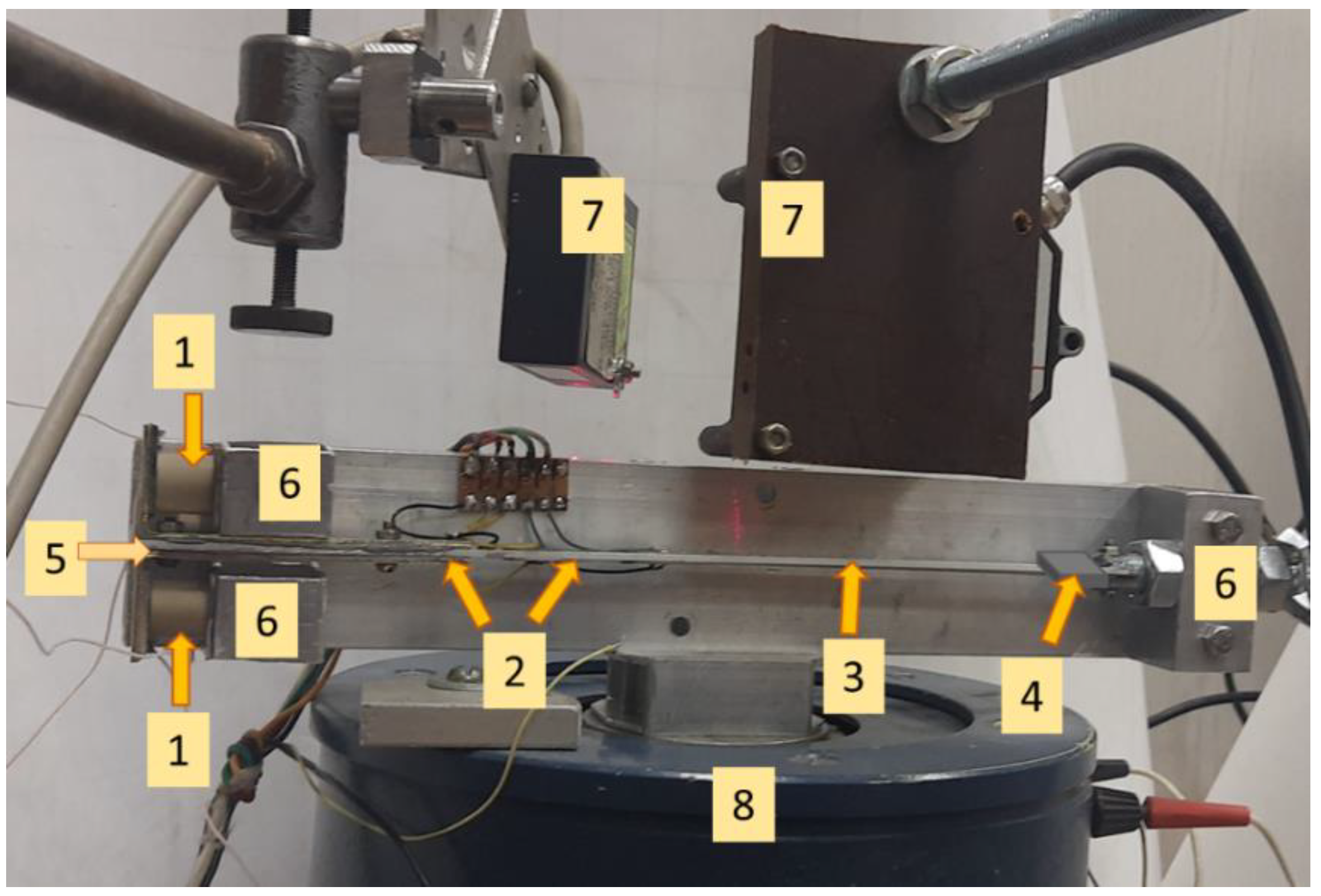
Figure 3.
Experimental setup: (1) piezoelectric cylinders, (2) piezoelectric bimorphs, (3) duralumin substrate, (4) proof mass (5) L-shaped steel plate, (6) rigid punching, (7) optical linear displacement transducers, (8) electromagnetic vibrator.
Figure 3.
Experimental setup: (1) piezoelectric cylinders, (2) piezoelectric bimorphs, (3) duralumin substrate, (4) proof mass (5) L-shaped steel plate, (6) rigid punching, (7) optical linear displacement transducers, (8) electromagnetic vibrator.
Figure 4.
(a) Finite element model and, (b) mode shape at the first-eigen frequency.
Figure 4.
(a) Finite element model and, (b) mode shape at the first-eigen frequency.
Figure 5.
Amplitude and eigen values (a) experimental and (b) numerical simulations.
Figure 5.
Amplitude and eigen values (a) experimental and (b) numerical simulations.
Figure 6.
Effect of porosity on natural frequency.
Figure 6.
Effect of porosity on natural frequency.
Figure 7.
Porosity variations effect on voltage and current: (a) piezoelectric bimorphs and cylinders, (b) total cumulative voltage vs first-eigen frequency at various porosity and, (c) current intensities at various porosities.
Figure 7.
Porosity variations effect on voltage and current: (a) piezoelectric bimorphs and cylinders, (b) total cumulative voltage vs first-eigen frequency at various porosity and, (c) current intensities at various porosities.
Figure 8.
Porosity effect on output power.
Figure 8.
Porosity effect on output power.
Figure 9.
Effect of position of proof mass and porosities.
Figure 9.
Effect of position of proof mass and porosities.
Figure 10.
Effect of resistances and output voltage.
Figure 10.
Effect of resistances and output voltage.
Figure 11.
Effect of various porosities and resistances on power.
Figure 11.
Effect of various porosities and resistances on power.
Figure 12.
Acceleration effect on: (a) total cumulative output voltage and, (b) power.
Figure 12.
Acceleration effect on: (a) total cumulative output voltage and, (b) power.
Table 1.
Geometric dimensions of energy harvester elements.
Table 1.
Geometric dimensions of energy harvester elements.
| No. | Name | Geometric Parameters, mm |
|---|
| 1 | Piezoelectric cylinder | dp | 14 | hp | 12.5 | | |
| 2 | Piezoelectric bimorph | lp | 20 | wp | 15 | tp | 0.5 |
| 3 | Duralumin base plate | al | 250 | aw | 15 | at | 2 |
| 4 | Proof mass | bm | 8 | hm | 8 | tm | 30 |
| 5 | L- shaped plate | lf | 74 | hf | 25 | tf | 2 |
| | | bf | 15 | | | | |
Table 2.
Mechanical properties of materials.
Table 2.
Mechanical properties of materials.
| Element Name | Materials Used | Density (kg/m3) | Young Modulus (GPa) | |
|---|
| Base Plate | duralumin | 2600 | 0.7 | 0.33 |
| Proof mass | steel | 7700 | 2.1 | 0.33 |
| L-clamping bar | steel | 7700 | 2.1 | 0.33 |
| Fixing supports | duralumin | 2600 | 0.7 | 0.33 |
| Active electric load | resistor | |
| Damping value | | |
Table 3.
Properties of the material of porous piezoelectric composite.
Table 3.
Properties of the material of porous piezoelectric composite.
| Porosity in (%) | 0 | 10 | 20 | 30 | 40 | 50 | 60 | 70 | 80 |
|---|
| Density(ρ), kg/m3 | 7500 | 6750 | 6000 | 5250 | 4500 | 3750 | 3000 | 2250 | 1500 |
| , 1010, N/m2 | 13.9 | 11.56 | 9.25 | 6.85 | 5.05 | 3.34 | 2.07 | 1.26 | 0.68 |
| , 1010, N/m2 | 7.78 | 6.15 | 4.66 | 3.14 | 2.10 | 1.16 | 0.62 | 0.28 | 0.13 |
| , 1010, N/m2 | 7.43 | 5.82 | 4.25 | 2.82 | 1.87 | 1.06 | 0.52 | 0.24 | 0.1 |
| , 1010, /m2 | 11.5 | 9.53 | 7.23 | 5.42 | 3.91 | 2.72 | 1.63 | 0.91 | 0.47 |
| , 1010, N/m2 | 2.56 | 2.23 | 1.83 | 1.44 | 1.10 | 0.74 | 0.44 | 0.23 | 0.1 |
| , C/m2 | −5.2 | −4.23 | −3.14 | −2.07 | −1.32 | −0.75 | −0.43 | −0.21 | −0.1 |
| , C/m2 | 15.1 | 13.38 | 11.37 | 9.59 | 7.68 | 5.93 | 3.93 | 2.30 | 1.25 |
| , C/m2 | 12.7 | 10.96 | 8.96 | 6.91 | 5.00 | 3.30 | 1.95 | 1.00 | 0.44 |
| /Ɛ0 | 730 | 663 | 582 | 509 | 439 | 349 | 263 | 191 | 122 |
| /Ɛ0 | 635 | 567 | 492 | 413 | 345 | 270 | 199 | 130 | 75 |
Table 4.
Comparison of results.
Table 4.
Comparison of results.
| Mode | Experimental | Numerical Simulation | Error, % |
|---|
| First eigen-frequency (EF), Hz | 275 | 283 | 2.83 |
| Second eigen-frequency (EF), Hz | 576 | 593 | 2.86 |
| Amplitude at first EF, mm | 0.205 | 0.226 | 9.2 |
| Amplitude at second EF, mm | 0.065 | 0.055 | 15.38 |
| Publisher’s Note: MDPI stays neutral with regard to jurisdictional claims in published maps and institutional affiliations. |
© 2022 by the authors. Licensee MDPI, Basel, Switzerland. This article is an open access article distributed under the terms and conditions of the Creative Commons Attribution (CC BY) license (https://creativecommons.org/licenses/by/4.0/).


 ,
, 


