Article

Asymmetric Etalon Effect in Fold-Type Optical Feedback Cavity-Enhanced Absorption Spectroscopy

College of Advance Interdisciplinary Studies, National University of Defense Technology, Changsha 410073, China
*
Author to whom correspondence should be addressed.
Appl. Sci. 2022, 12(19), 10031; https://doi.org/10.3390/app121910031
Submission received: 23 August 2022 / Revised: 19 September 2022 / Accepted: 4 October 2022 / Published: 6 October 2022
(This article belongs to the Section Optics and Lasers)

Abstract

:
To further improve the performance of cavity-enhanced spectroscopy systems, a high-quality U-cavity system was established. In the process of the experiment, an asymmetric ripple effect, which is different from the previous etalon effect, was found, which seriously affects the performance of the spectral system. This unique phenomenon mainly manifests in the different amplitudes of the fluctuations of the spectral curves measured by the folding mirror and the end mirror in the U-cavity system. Based on multi-beam interference theory, we analyzed the characteristics of the transmission spectrum of each mirror in the presence of the etalon effect at the end mirror, and obtained the following conclusions: for the U-cavity system, the strength of the etalon effect of each mirror is inversely proportional to its transmission loss value, that is, the larger the loss, the smaller the ripple of the transmission spectrum, and vice versa. In order to eliminate this effect, the most effective way is to eliminate the etalon effect caused by the light feedback of the end mirror. After improving the system, the minimum detectable absorption coefficient of α min = 8.33 × 10 9 cm 1 is obtained with this U-shape Optical Feedback Cavity-Enhanced Absorption Spectroscopy. These works are valuable references for the design of folded Cavity-Enhanced Absorption Spectroscopy systems and have potential for laser wavelength calibration and measurement of a mirror’s reflectance.

1. Introduction

Trace gas analysis is widely applied in environmental detection, atmospheric science, medical diagnoses, and industrial agricultural process control [1,2,3]. Laser spectroscopy can provide high precision concentration detection of trace gas with fast response, large range and high resolution among different coexisting species. The most common approaches are based on infrared absorption technologies, such as non-dispersive infrared absorption (NDIR) [4,5], cavity ring-down spectroscopy (CRDS) [6], cavity-enhanced absorption spectroscopy(CEAS) [7].
CEAS is an essential technology in laser spectroscopy. In 1998, this technique was proposed to facilitate CRDS by Engeln et al. [7,8,9]. In principle, CEAS and CRDS enhance the effective absorption path by the relaxing effect of the high-quality passive optical cavity. When the laser meets resonance conditions, the effective absorption path of the absorbing medium increases thousands of times [10]. Unlike CRDS, CEAS obtains the absorption spectrum by measuring the transmitted light intensity of the resonant cavity, and does not require expensive light modulators such as optical switches. Therefore, the CEAS system is compact, cheaper and suitable for commercial application.
Since the peak stability of resonant light in CEAS technology directly affects the minimum detectable absorption coefficient, the most effective method to improve the sensitivity of CEAS is frequency stabilization technology. Currently, the primary laser frequency stabilization technology mainly includes Pound-Drever-Hall technology [11] and optical feedback frequency locking [12]. This paper presents a compact optical feedback Cavity-Enhanced Absorption Spectroscopy (OF-CEAS) system setup with a high-finesse passive U-shaped cavity. During the study of this system, a special asymmetric etalon effect is observed, which is different from the etalon effect observed in V-shaped cavity CEAS systems during our previous works [13]. These adverse effects limit system performance and application range. In order to reveal the physical mechanism of this phenomenon, the transmission spectrum of each mirror was analyzed and discussed according to the multi-beam interference. Ways to prevent this phenomenon are also proposed. After eliminating the interference of this phenomenon on spectral line measurement, the accuracy is improved, and the OF-CEAS system with the minimum detectable coefficient αmin = 8.33 × 10⁻⁹ cm−1 was obtained. These works have guiding significance for the performance improvement of the CEAS system.

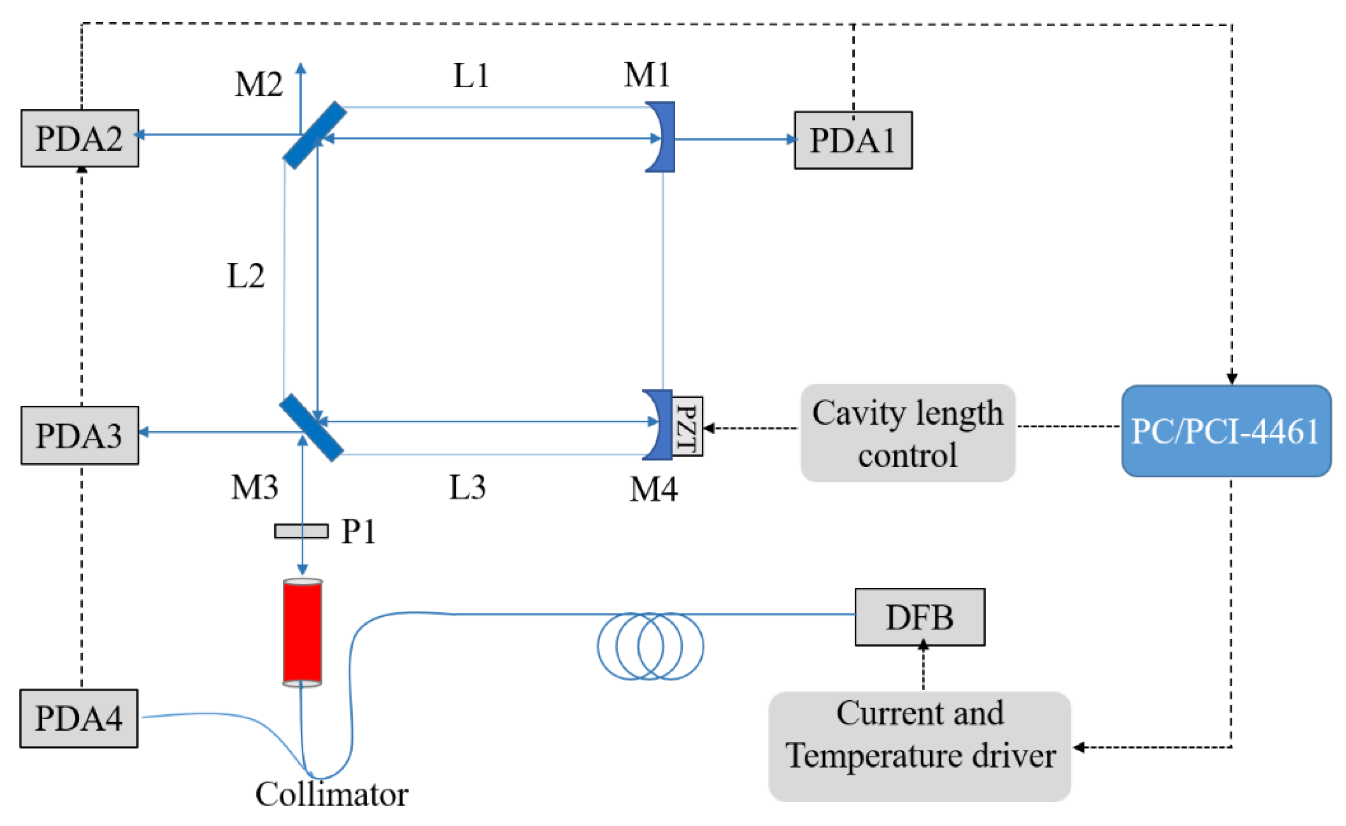
2. Experimental Apparatus and Measurement Principle

CEAS is essentially a direct absorption spectroscopy technology that follows the Beer-Lambert law. By direct measurement of the optical cavity transmitted light field, the absorption coefficient of gas is measured in the cavity bonding Equation (1):
I ( λ ) = I 0 ( λ ) exp [ α ( λ ) L ]
where I ( λ ) denotes the signal of transmitted light; λ denotes the light frequency; I 0 ( λ ) represents the incident light intensity; and L is the effective absorption path. α represents the gas absorption coefficient, which can be described as in Equation (2):
α ( λ ) = C N S ( λ ) g ( λ λ 0 )
where C represents the concentration of the absorbing gas; N represents the molecular number density; S represents the spectral line intensity; and g ( λ λ 0 ) is the normalized line profile. CEAS realizes the multiplication of effective absorption paths (100–10,000 times), depending on the relaxation effect of the ultra-low loss optical cavity. The detection sensitivity and limit of trace gas concentration can be improved greatly. As an improvement of CEAS, OF-CEAS can effectively increase the laser injection rate of the high finesse optical cavity. In OF-CEAS, a portion of the resonance light returned to the laser. When the feedback optical field has been matched in phase and feedback rate, the semiconductor laser’s linewidth can be effectively narrowed, and the laser frequency can be locked with the resonance frequency of the high finesse optical cavity [14,15,16]. As a result, the transmitted light intensity and sensitivity of the cavity will be significantly improved compared to conventional CEAS [16].
A distributed feedback semiconductor laser (SWLD-151210P22-09, Allwave Lasers, Xi’an, China) was adopted as the light source for the system. As shown in Figure 1, the working state of the distributed feedback laser is controlled by a high precision temperature driver and current driver. The light from the distributed feedback laser is injected into a single-mode polarization-maintaining (PM) fiber. The pigtail output is connected with an optical fiber coupler (50:50, 1550 nm Center Wavelength). The two output ports of the fiber coupler are separately linked to the adaptable fiber collimator and the optical detector PDA4 (PDA10CS-EC, Thorlabs, Newton, NJ, USA). The cavity is a U-shaped cavity consisting of three arms and two 45° folding angles. The length of L1 and L3 is 170 mm, the length of L2 is 132 mm and the circumference is 472 mm. The cavity body used is glass-ceramic with an ultralow expansion coefficient (~10−8/°C). The cavity includes four mirrors made of fused quartz (diameter is 25 mm). Among them, the mirrors M2 and M3 are plane mirrors, and the mirrors M1 and M4 are spherical mirrors with a radius of curvature of 2 m. An ultra-high reflectivity film (diameter is 10 mm, R > 99.99% at 1530 ± 30 nm) lies in the central region of the mirror. Piezoelectric ceramic transducer (PZT) for the cavity length scanning is installed behind the spherical mirror M4. Compared with the V-shaped cavity, the design of the U-shaped cavity can not only realize the optical feedback effect, but also collect the transmitted light intensity signal by setting a photodetector (PDA3) at the position of the first reflected light. For Pound-Drever-Hall (PDH) frequency stabilization technology, the first reflected light of the optical cavity is the source of an error signal. Therefore, the combination of optical feedback and PDH frequency stabilization technology can be realized in the same CEAS system, which may improve the detection sensitivity of the system.
To improve the efficient coupling of laser radiation into cavity resonances, the incident light spot radius is set to 0.556 mm by adjusting the zoom fiber collimator. For a U-shaped cavity, the non-vertical reflection in the folded mirror produces slightly different phase shifts between the S-polarized light and the P-polarized light. The optical cavity forms two stable, separated resonant modes in the s-polarization direction and p-polarization direction, respectively. The simultaneous presence of two resonant modes reduces the stability of the transmitted light field [17]. A linear polarizer is set between the collimator and mirror M3, which ensures S-polarized light injects into the cavity.
During the absorption spectrum measurement, we set the working temperature of the DFB laser at 21 °C and the scanning range of injection current at 40–120 mA. The DFB semiconductor laser can realize continuous scanning in the range of 1510–1512 nm calibrated by the wavelength meter (WA-1500-NIR, EXFO Burleigh, Quebec City, QC, Canada). The PZT modulates the cavity length by a triangular wave signal with an amplitude of 200 V and a frequency of 20 Hz. When resonance occurs, PDA1 (PDAL0CS-E, Thorlabs, Newton, NJ, USA) detects part of the transmitted signal and the high-speed acquisition card acquires this signal. The measurement program takes the peak intensity of the resonance signal corresponding to the scanning current as the cavity enhancement spectrum signal. The PDA4 obtains the real-time laser intensity and it is used as a reference to eliminate the effects caused by variations in laser power. According to the multi-beam interference theory and the Beer-Lambert law, the molecular absorption coefficient in the cavity can be obtained as Equation (3) [18]:
α ( λ ) = 1 R e f f ( λ ) L ( I 0 ( λ ) I ( λ ) 1 )
where α represents the gas absorption coefficient; Reff denotes the effective reflectivity calculated by the loss of “empty cavity”; L represents the cavity length; and I and I0 are the transmitted light intensities in the presence and absence of gas absorption, respectively. According to Equations (2) and (3) and the HITRAN database [19], we can obtain the concentration of absorbing gas molecules. Unlike conventional CEAS systems, the spectral resolution of the system is not limited by the free spectral range (FSR) when performing spectral scanning. In our experimental system, the PZT mounted on M4 (shown in Figure 1) can precisely modulate the cavity length to realize cavity resonance. The spectral resolution is mainly determined by the tuning resolution of the DFB semiconductor laser. Thus, our system improves the spectral resolution to 0.003 cm−1.

3. Experimental Phenomenon and Theoretical Analysis

Our main study is to measure the absorption spectrum of water vapor around 6621.5 cm−1. A DFB diode laser with a central wavelength of 1510 nm is used to match several absorption lines of H2O in the cavity. In the case of the laser current tuning from 40 to 120 mA, the range is about 3.5 cm−1 during the scanning spectral range of 6619.25–6622.75 cm−1. We take the peak intensity of the transmitted signal of the optical cavity as the cavity enhancement spectral signal.

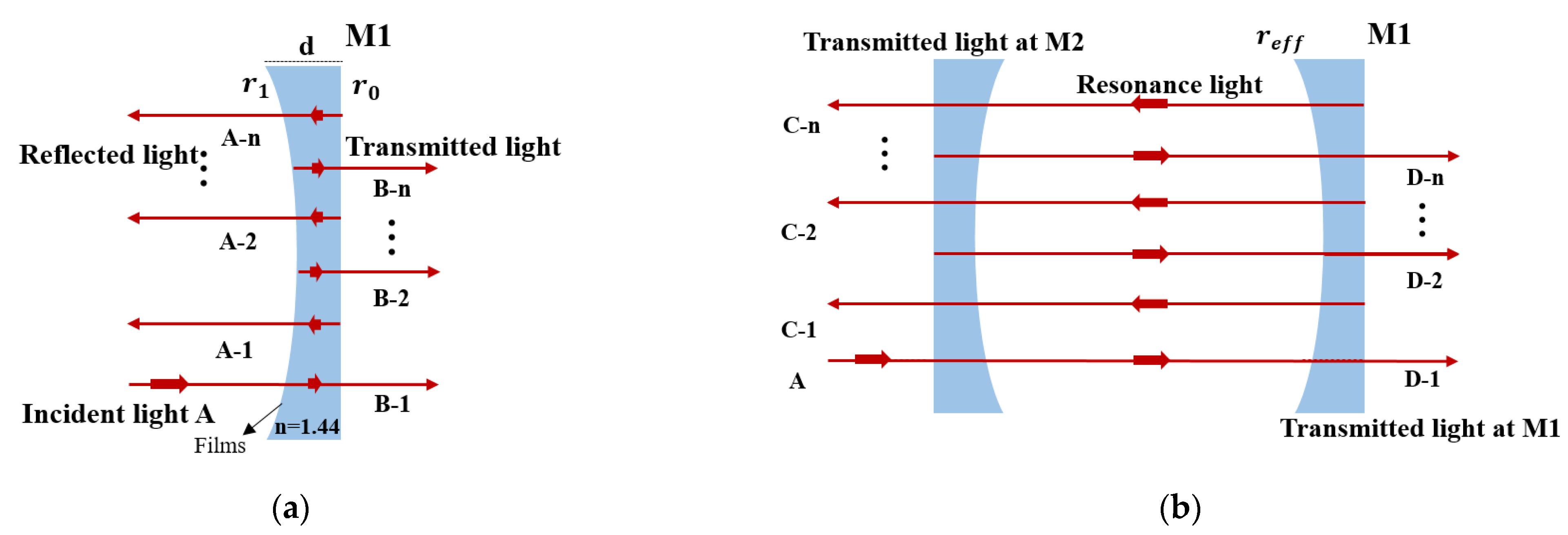
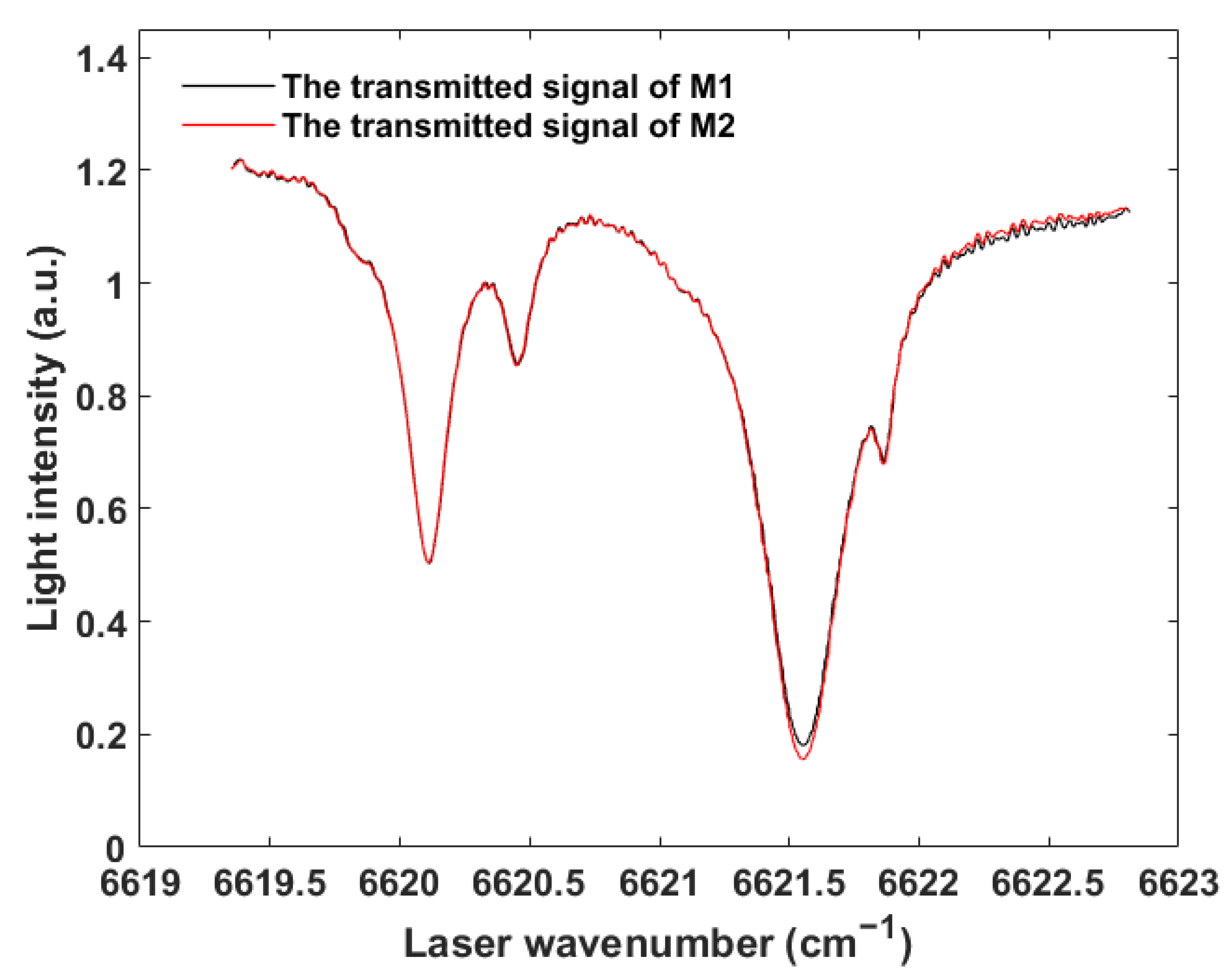
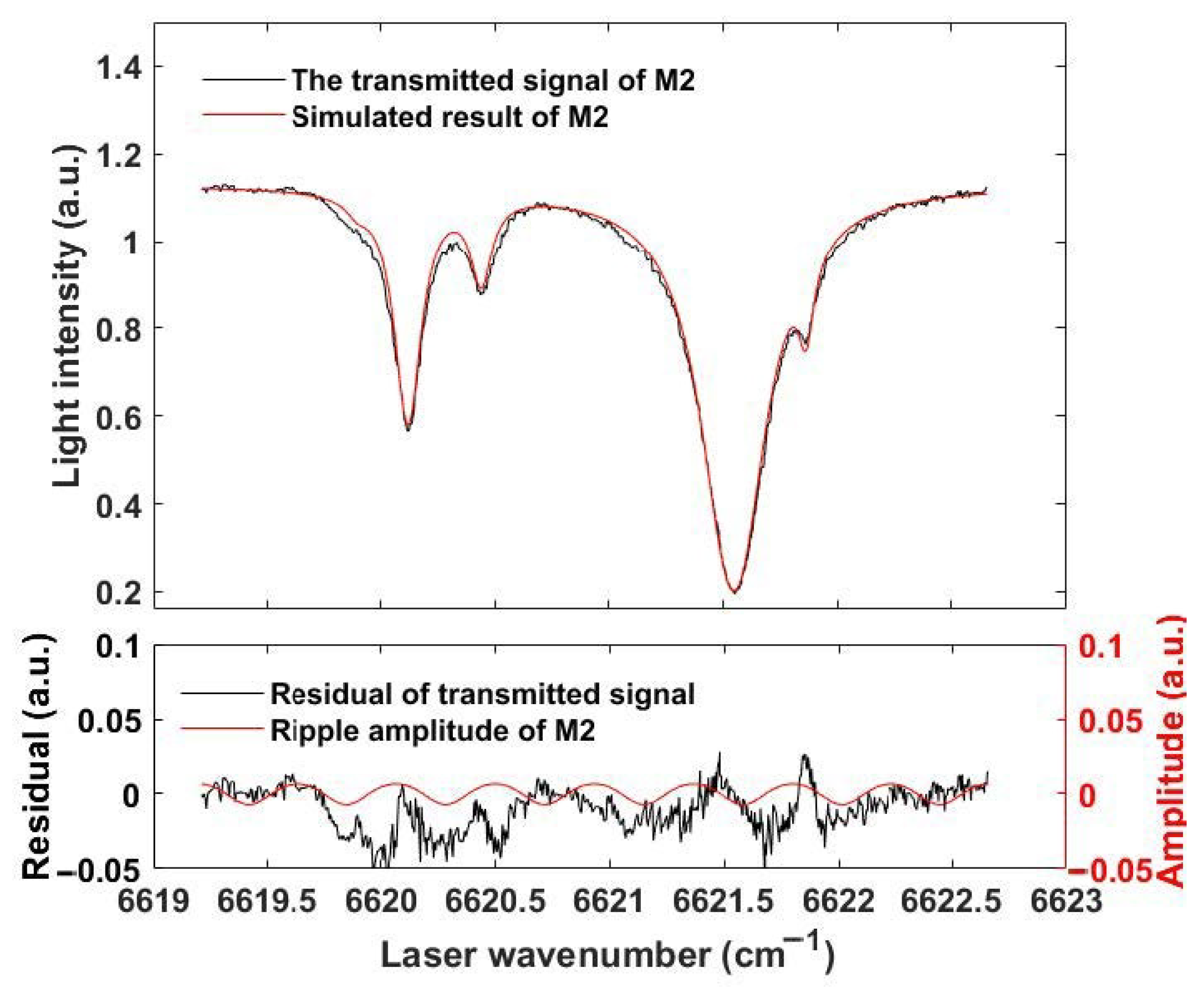
3.1. Asymmetric Etalon Effect Phenomenon and Theoretical Analysis

As shown in Figure 2, cavity-enhanced absorption spectra were detected at M1 and M2, respectively, and the measured results show that they have different characteristics. Specifically, the spectral data obtained after M1 has a ripple phenomenon except for some absorption lines during the laser’s current tuning from 40 to 120 mA, while the data obtained after M2 does not. According to the conclusion of the previous analysis [20,21], the spectral ripple effect is usually caused by the periodic change of the optical resonator loss with spectral scanning. In this case, the theoretical characteristics of the spectral data obtained after M1 and M2 should be the same, only the amplitude of the ripple is different. In fact, it can be seen that almost no ripple is found in the spectral data after M2. The ripple has significant interference with the absorption peak measurement, affecting the accuracy of spectral measurement and the minimum detectable absorption coefficient. In addition, this asymmetric etalon effect phenomenon significantly impacts the calibration of “empty cavity loss” by cavity ring-down (CRD) [22,23]. Therefore, the mechanism of this phenomenon needs to be re-examined, and measures are taken to eliminate it.
In this experiment, the optical resonator used is a U-shaped structure. In this case, the reflection of the surface behind M2 and M3 folded mirrors will not lead to the occurrence of the etalon effect due to the large incidence angle and large substrate thickness (~8 mm). However, for the end mirror M1, since the laser is incident vertically, the backside reflection of the cavity mirror substrate will introduce optical feedback, which forms an etalon with the coated reflection surface (with the surface light intensity reflectivity R0 = 3.32% and R1 ≈ 99.999% for λ = 1530 nm). The light beam (A) at the mirror is split into multiple beams (shown in Figure 3a as A(n) and B(n)) by the two surfaces of M1 before coupling into the cavity. This reflecting process will produce an optical path difference between these beams. It can be inferred that the ripple effect of the M1 spectrum is caused by the multi-beam interference between the feedback light from the M1 substrate and the cavity resonance light. The transmission losses of M1 and M2 were measured using the cavity ring-down technique, and the results show that the transmission loss was about 10 ppm for M1 and 90 ppm for M2. There is a huge difference in the loss between the folded mirror and the end mirror. Therefore, this asymmetric etalon effect may be caused by the different losses of the two mirrors. To verify the conjecture, the transmission loss of the folding mirror M2 is changed, and the transmitted optical fields of M1 and M2 are simulated.
The laser beam is Gaussian, considering the incident light A as follows in Equation (4):
E i ( t ) = A 0 e i ( ω t + k x ) ( ω = 2 π ν )
The spherical mirror has a divergent effect on the feedback light from the substrate, which causes the waist radius of the feedback light to increase. The coupling efficiency of the reflected light A(n) is calculated ϕ = 50 % according to mode coupling theory and Gaussian beam transform law [24,25]. Based on the multi-beam interference theory, the effective reflection and transmission coefficients of mirror M1 are calculated respectively as Equation (5) and Equation (6):
r e f f = ( r 1 + ϕ r 0 e 2 i δ 0 ) / ( 1 + ϕ r 1 r 0 e 2 i δ 0 )
t e f f = ( ( 1 r 1 2 ) ( 1 ϕ 2 r 0 2 ) e i δ 0 ) / ( 1 + ϕ r 1 r 0 e i 2 δ 0 )
where δ 0 = n d cos ( θ ) 2 π / λ , n is the reflective index of quartz glass ( n = 1.444 ), d is the thickness of M1 (d = 8 mm), r 0 , r 1 , r 2 , r 3 and r 4 represent the amplitude reflectivity of the mirror surface ( r 0 2 = 0.0332 , r 1 2 = r 4 2 = 0.99999 , r 2 2 = r 3 2 = 0.99991 , calibration by cavity ring-down). The reflection coefficient r 1 can be replaced by the effective reflection coefficient r e f f , when the multi-beam interference occurs in the U-shaped cavity (as shown in Figure 3b).
Consider that the resonant field of the U-shaped cavity is the TEM00 fundamental mode. By the integral operation, the total coupling light of the transmitted light field at M1 is calculated as Equation (7):
E T 1 = A 0 ( 1 r 3 2 ) r 2 t e f f · e i ( ω t + k x ) e i ( δ 1 + δ 2 ) ψ
A total interference transmitted light field at M2 is calculated as Equation (8):
E T 2 = A 0 ( 1 r 3 2 ) ( 1 r 2 2 ) r 2 r e f f · e i ( ω t + k x ) e i ( 2 δ 1 + δ 2 ) ψ
Here, ψ = 1 / ( 1 r 2 2 r 3 2 r 4 r e f f e 2 i δ ) , δ 0 = n d cos ( θ ) 2 π / λ , δ 1 = L 1 2 π / λ , δ 2 = L 2 2 π / λ , δ = 2 δ 1 + δ 2 , L 1 and L 2 is the length of each cavity arm ( L 1 = L 3 = 170   m m , L 2 = 132   m m ).
Considering that the transmission losses of mirrors M1 and M2 are different, the corresponding ripple amplitude of the transmission light intensity is different. According to the above mathematical model, the transmitted light intensity and ripple amplitude of the resonator with different loss mirrors are simulated. The transmission loss of mirror M1 (T1 = 1 − R1) is set to 10 ppm, and the transmission loss of mirror M2 (T2 = 1 − R2) varies from 10 ppm to 210 ppm. The simulation results are shown in Figure 4:
As shown in Figure 4a, the transmission loss T1 of the end mirror M1 is unchanged. As the transmission loss of the folded mirror M2 gradually increases, the ripple amplitude of the transmission spectrum of M2 gradually decreases. When the transmission losses of M1 and M2 are 10 ppm and 100 ppm, respectively, the ripple amplitude of M1 (~0.2) is much larger than that of M2 (~6 × 10⁻³). As shown in Figure 4b, the ripple amplitude of the transmission spectrum of folded mirror M2 is inversely proportional to its transmission loss value, that is, the larger the loss of M2, the smaller the ripple of the transmission spectrum. For the end mirror M1, as the loss of M2 increases, the relative loss of M1 (T1:T2) decreases and the M1 ripple amplitude increases. It can be inferred that the main reason for the phenomenon of asymmetric etalon effect is that the loss of the folded mirror M2 is much larger than that of the end mirror M1, and the weak ripple is easily drowned by system noise.

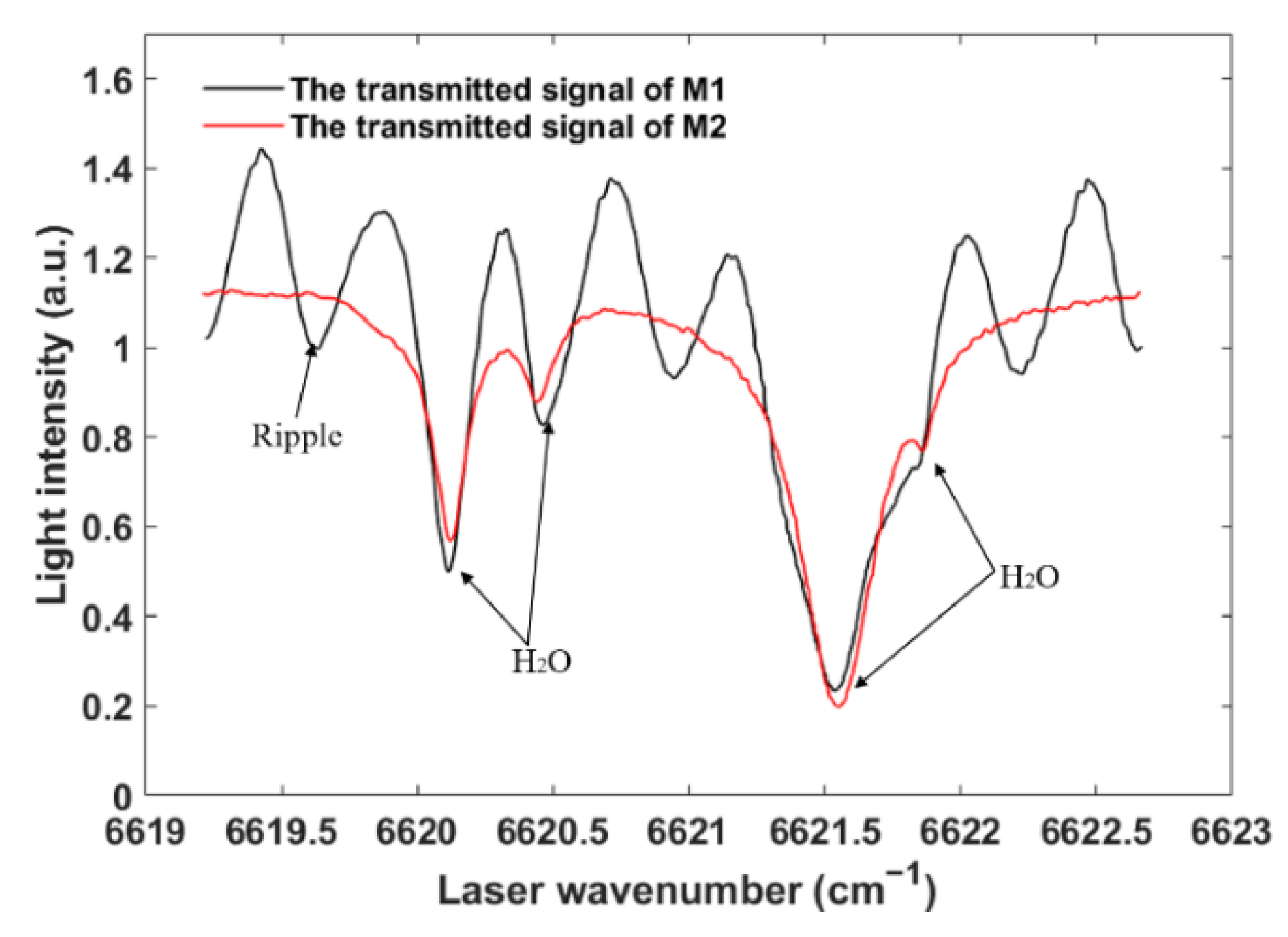
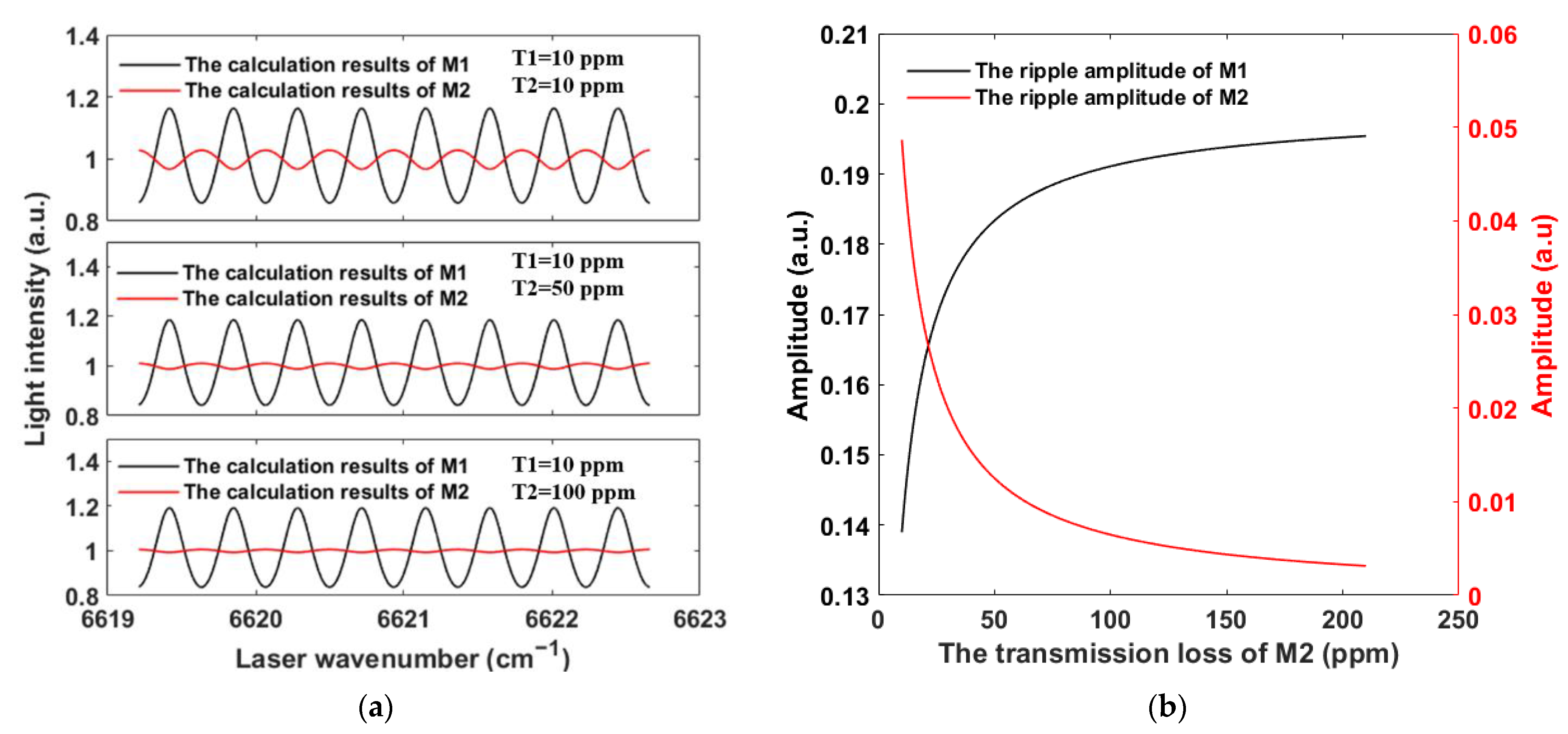
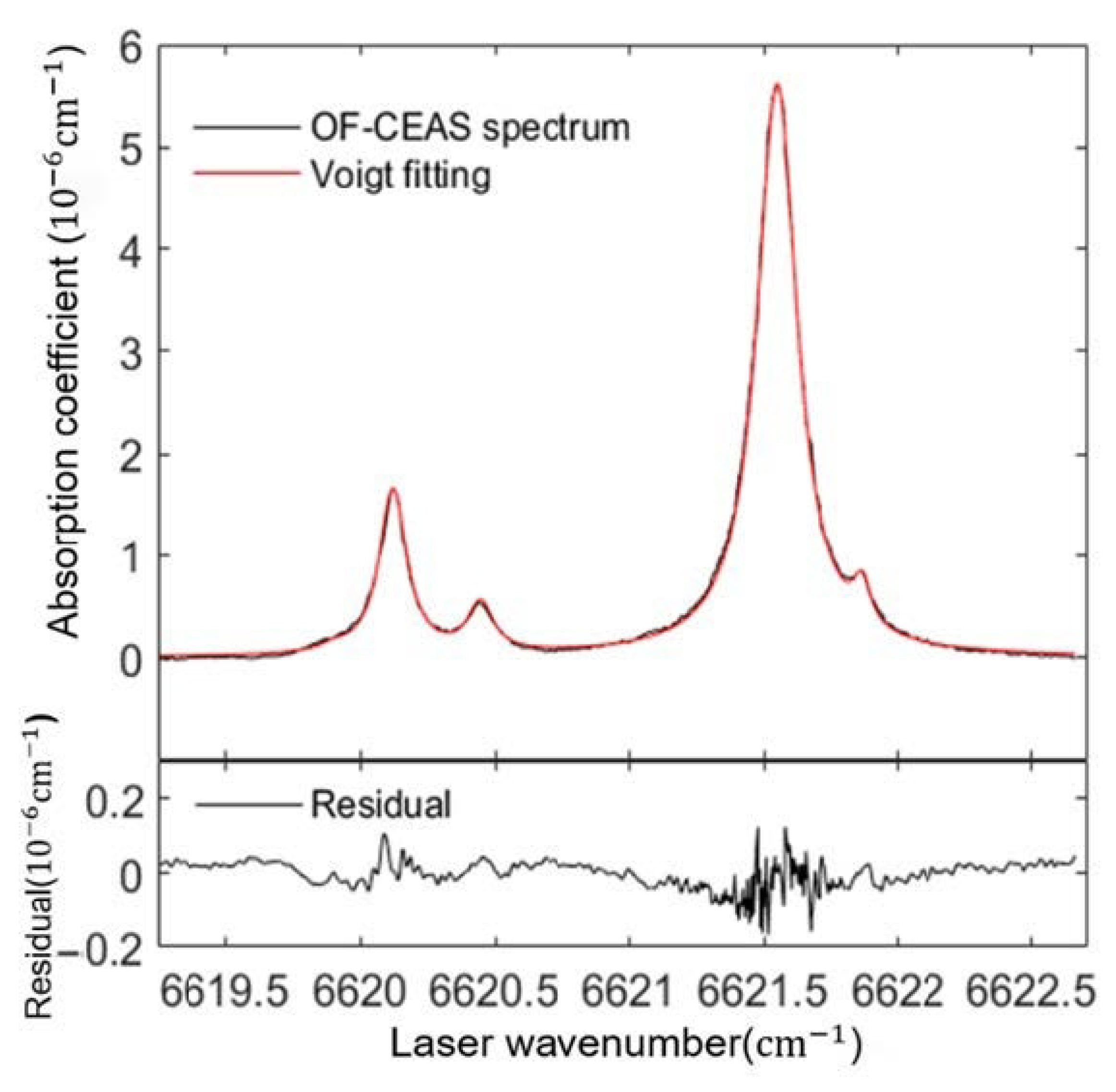
3.2. Experimental Results and Discussion

To further verify the theoretical results, the minimum detectable light intensity of the system (sensitivity) needs to be calculated. The residual between the measured data and the spectra fitted in the absence of the etalon effect represents the system’s sensitivity.
Firstly, it is necessary to eliminate this special effect. The most effective way is to eliminate the etalon effect caused by the feedback light from the end mirror. Depending on the application requirements of the optical cavity, “optically glued prisms or spherical mirrors with different radius of curvature” can be selected to attenuate or eliminate this phenomenon. Among all the current methods, “optically glued prism” is the most practical method in our experimental setup. Therefore, a prism is optically glued onto the back of M1, which can fully destroy the two surfaces parallel to the mirror to eliminate this asymmetric etalon effect. The results of the OF-CEAS signal measurement are shown in Figure 5. The periodic spectral fluctuation of M1 disappears, and four absorption peaks can be observed in this experimental result.
Then, after eliminating this symmetric etalon effect, the residual water vapor concentration in the cavity was set to 1.5% (corrections were made based on experimental results), the transmission signal of M2 in the presence of absorption was simulated according to Equation (3) and the HITRAN 2020 database. The fitting residual results of M2 are shown in Figure 6, the standard deviation of the fitted residuals of the measured signal is 8.18 × 10⁻³, larger than the theoretical ripple amplitude of M2 of 6.5 × 10⁻³. The experimental results agree well with the theoretical simulations, and it is clear that the ripple effect of the folded mirror M2 is too weak to be detected by the system.
In summary, since the loss of the mirror is inversely proportional to the ripple amplitude, the ripple amplitude of the folded mirror is much smaller than that of the end mirror. The ripple with less than the minimum detectable light intensity cannot be measured by the system. Finally, the CEAS spectrum is calculated according to Equation (3), and the results are shown in Figure 7.
As is shown in Figure 7, four water vapor absorption peaks can be accurately measured by the improved system. The absorption coefficient can be obtained by Equation (3). The “empty cavity” ring down time τ 0 is 8.2   μ s at 1510 nm, the cavity corresponding loss is 191.8 ppm in a single pass, and the equivalent reflectivity R l o s s  is 0.9998082. A minimum detectable absorption coefficient of αmin = 8.33 × 10⁻⁹ cm−1 can be obtained by the standard deviation of the fitting residuals. The experimental results indicate that the precision of cavity-enhanced absorption spectroscopy for the detection of trace gases is much improved.

4. Conclusions

In conclusion, we have presented a fibered OF-CEAS system with an enhanced spectral resolution based on a U-shape cavity. In the experiment, an asymmetric ripple effect is observed, which seriously affects spectral measurements. A theoretical and experimental study is presented for this unique phenomenon. The results show that this phenomenon is caused by the different losses of each cavity mirror (the larger the loss of the reflector, the smaller the ripple amplitude). This spectral fluctuation can be effectively eliminated by optically gluing a prism to the back of the end mirror. After system optimization, the OF-CEAS system with the minimum detectable coefficient αmin = 8.33 × 10⁻⁹ cm−1 was obtained. These works have guiding significance for the performance improvement of the CEAS system.
Considering the characteristics of the asymmetric ripple effect in U-cavity enhanced spectroscopy systems, several potential applications are proposed. Cavity ring-down systems for measuring the spectrum loss of mirrors require high-performance optical switches and photodetectors. After eliminating the ripple effect, the system can measure the spectrum loss of highly reflective mirrors by detecting the intensity of transmitted light from different mirrors. In addition, the laser wavelength can be calibrated by changing the thickness of the end mirror and measuring the ripple period of the enhanced spectral signal of the end mirror cavity. Unlike the traditional cavity-enhanced absorption spectroscopy system, the U-cavity-enhanced spectroscopy system has a more straightforward scheme and a more comprehensive application range.

Author Contributions

Conceptualization, Y.W. and Z.T.; methodology, Z.T.; software, Y.W.; validation, Y.W., S.G. and H.C.; formal analysis, Y.W.; investigation, H.C.; resources, Z.T.; data curation, S.G.; writing—original draft preparation, Y.W.; writing—review and editing, S.G. and Z.T.; visualization, Y.W.; supervision, Z.T.; project administration, Z.T.; funding acquisition, Z.T. All authors have read and agreed to the published version of the manuscript.

Funding

This research was funded by the National Natural Science Foundation of China (No. 12004435), the Hunan Provincial Innovation Foundation for Postgraduate (No.CX2020001).

Institutional Review Board Statement

Not applicable.

Informed Consent Statement

Not applicable.

Data Availability Statement

The data that support the findings of this study are available from the corresponding authors upon reasonable request.

Conflicts of Interest

The authors declare no conflict of interest.

References

  1. Wang, C.; Sahay, P. Breath Analysis Using Laser Spectroscopic Techniques: Breath Biomarkers, Spectral Fingerprints, and Detection Limits. Sensors 2009, 9, 8230–8262. [Google Scholar] [CrossRef] [PubMed]
  2. Wojtas, J.; Mikolajczyk, J.; Nowakowski, M.; Rutecka, B.; Medrzycki, R.; Bielecki, Z. Applying CEAS method to UV, VIS, and IR spectroscopy sensors. Bull. Pol. Acad. Sci. Tech. Sci. 2011, 59, 415–418. [Google Scholar] [CrossRef] [Green Version]
  3. Luo, Z.; Tan, Z.; Long, X. Application of Near-Infrared Optical Feedback Cavity Enhanced Absorption Spectroscopy (OF-CEAS) to the Detection of Ammonia in Exhaled Human Breath. Sensors 2019, 19, 3686. [Google Scholar] [CrossRef] [PubMed] [Green Version]
  4. Gibson, D.; Macgregor, C. A Novel Solid State Non-Dispersive Infrared CO2 Gas Sensor Compatible with Wireless and Portable Deployment. Sensors 2013, 13, 7079–7103. [Google Scholar] [CrossRef] [PubMed] [Green Version]
  5. Song, J.; Xin, M.; Rao, W.; Hong, Y.; Feng, G. Integral absorbance measurement for a non-uniform flow field using wavelength modulation absorption spectroscopy. Appl. Opt. 2021, 60, 5056. [Google Scholar] [CrossRef] [PubMed]
  6. Morville, J.; Romanini, D.; Kachanov, A.A.; Chenevier, M. Two schemes for trace detection using cavity ringdown spectroscopy. Appl. Phys. B 2004, 78, 465–476. [Google Scholar] [CrossRef]
  7. Engeln, R.; Berden, G.; Peeters, R.; Meijer, G. Cavity enhanced absorption and cavity enhanced magnetic rotation spectroscopy. Rev. Sci. Instrum. 1998, 69, 3763–3769. [Google Scholar] [CrossRef] [Green Version]
  8. Gherman, T.; Venables, D.S.; Vaughan, S.; Orphal, J.; Ruth, A.A. Incoherent broad-band cavity-enhanced absorption spectroscopy. Chem. Phys. Lett. 2003, 42, 890–895. [Google Scholar]
  9. O’Keefe, A.; Deacon, D.A.G. Cavity ring-down optical spectrometer for absorption measurements using pulsed laser sources. Rev. Sci. Instrum. 1988, 59, 2544–2551. [Google Scholar] [CrossRef] [Green Version]
  10. Manfred, K.M.; Ciaffoni, L.; Ritchie, G.A.D. Optical-feedback cavity-enhanced absorption spectroscopy in a linear cavity: Model and experiments. Appl. Phys. B 2015, 120, 329–339. [Google Scholar] [CrossRef]
  11. Hodges, J.T.; Layer, H.P.; Miller, W.W.; Scace, G.E. Frequency-stabilized single-mode cavity ring-down apparatus for high-resolution absorption spectroscopy. Rev. Sci. Instrum. 2004, 75, 849–863. [Google Scholar] [CrossRef]
  12. Morville, J.; Kassi, S.; Chenevier, M.; Romanini, D. Fast, low-noise, mode-by-mode, cavity-enhanced absorption spectroscopy by diode-laser self-locking. Appl. Phys. B 2005, 80, 1027–1038. [Google Scholar] [CrossRef]
  13. Pei, S. The Study of cavity enhanced absorption spectroscopy and application. Chin. Acad. Sci. 2005, 36, 92–94. [Google Scholar]
  14. Dahmani, B.; Hollberg, L.; Drullinger, R. Frequency stabilization of semiconductor lasers by resonant optical feedback. Optics Letters 1987, 12, 876–878. [Google Scholar] [CrossRef]
  15. Motto-Ros, V.; Morville, J.; Rairoux, P. Mode-by-mode optical feedback: Cavity ringdown spectroscopy. Appl. Phys. B 2007, 87, 531–538. [Google Scholar] [CrossRef]
  16. Landsberg, J.; Romanini, D.; Kerstel, E. Very high finesse optical-feedback cavity-enhanced absorption spectrometer for low concentration water vapor isotope analyses. Opt. Lett. 2014, 39, 1795–1798. [Google Scholar] [CrossRef] [PubMed]
  17. Guan, S.; Chen, D.; Cao, H.; Tan, Z. Study of a Mode Separation Due to Polarization Existing in a Cavity-Enhanced Absorption Spectroscopy. Sensors 2021, 21, 7101. [Google Scholar] [CrossRef] [PubMed]
  18. O’Keefe, A.; Scherer, J.J.; Paul, J.B. Cw Integrated cavity output spectroscopy. Chem. Phys. Lett. 1999, 307, 343–349. [Google Scholar] [CrossRef]
  19. Ieg, A.; Lsr, A.; Rjh, A.; Rh, A.; Evk, A.; Fms, A.; Ekc, A.; Ch, B.; Rvkac, D.; Yta, E. The HITRAN2020 molecular spectroscopic database. J. Quant. Spectrosc. Radiat. Transf. 2021, 277, 107–949. [Google Scholar]
  20. Luo, Z.; Tan, Z.; Long, X. Study of a periodic spectral fluctuation existing in a fibered optical feedback cavity-enhanced absorption spectroscopy (OF-CEAS). J. Eur. Opt. Soc. Rapid Publ. 2019, 15, 23. [Google Scholar] [CrossRef] [Green Version]
  21. Tan, Z.; Long, X.; Huang, Y.; Wu, S. Etaloning Effects in Continuous-Wave Cavity Ring down Spectroscopy. Chin. J. Lasers 2008, 35, 1563–1566. [Google Scholar]
  22. Hosaka, K.; Inaba, H.; Akamatsu, D.; Yasuda, M.; Sugawara, J.; Onae, A.; Hong, F. A Fabry-Perot Etalon with an Ultralow Expansion Ceramic Spacer. Jpn. J. Appl. Phys. 2013, 52, 032402. [Google Scholar] [CrossRef]
  23. Lumeau, J.; Glebov, L.B.; Smirnov, V. Tunable narrowband filter based on a combination of Fabry-Perot etalon and volume Bragg grating. Opt. Lett. 2006, 31, 2417–2419. [Google Scholar] [CrossRef] [PubMed]
  24. Anderson, D.Z. Alignment of resonant optical cavities. Appl. Opt. 1984, 23, 2944–2949. [Google Scholar] [CrossRef] [PubMed]
  25. Siegman, A.E. Laser beams and resonators: The 1960s. IEEE J. Sel. Top. Quantum Electron. 2011, 6, 1380–1388. [Google Scholar] [CrossRef]
Figure 1. Experimental device structure diagram of U-shaped CEAS. M1–M4: mirrors; DFB: distributed feedback semiconductor laser; P1: line polarizer; PDA: photodetector; PZT: piezoelectric ceramic transducer.
Applsci 12 10031 g001
Figure 2. The normalized OF-CEAS transmitted light signal detected at M1 (black) and M2 (red). The spectrum detected at M1 presents a periodic spectrum fluctuation including four absorption lines. The spectrum detected at M2 only has four absorption lines.
Applsci 12 10031 g002
Figure 3. (a) shows the incident light A split into multiple beams A-n and B-n at the mirror M1; (b) shows the multi-beam interference of the U-shaped cavity by using a effective reflection coefficient.
Applsci 12 10031 g003
Figure 4. (a) Simulated transmitted light intensity of M1 and M2 with different transmission loss; (b) Ripple amplitude variation curve with transmission loss of M2.
Applsci 12 10031 g004
Figure 5. The OF-CEAS cavity transmitted signal optically glued onto a wedge mirror. The OF-CEAS cavity transmitted signal of M1 (black). The OF-CEAS cavity transmitted signal of M2 (red).
Applsci 12 10031 g005
Figure 6. The cavity transmitted light signal of M2 (black). The simulated transmitted light of M2 (red) without etalon effect. The simulated results without etalon effect are based on Equation (3) and HITRAN 2020 (P = 1.0 atm, T = 25 °C). The bottom shows the residuals of the measured signal (black) and the ripple amplitude of M2.
Applsci 12 10031 g006
Figure 7. The absorption coefficient spectrum (black) and Voigt fitting of the absorptions of molecular H2O (red) based on HITRAN 2020 (P= 1.0 atm, T = 25 °C); the bottom shows the fit residual.
Applsci 12 10031 g007
Publisher’s Note: MDPI stays neutral with regard to jurisdictional claims in published maps and institutional affiliations.

