
An Exploration into Damage Repair and Manufacturing Technology of Photomask Glass Substrates


Abstract
:1. Introduction
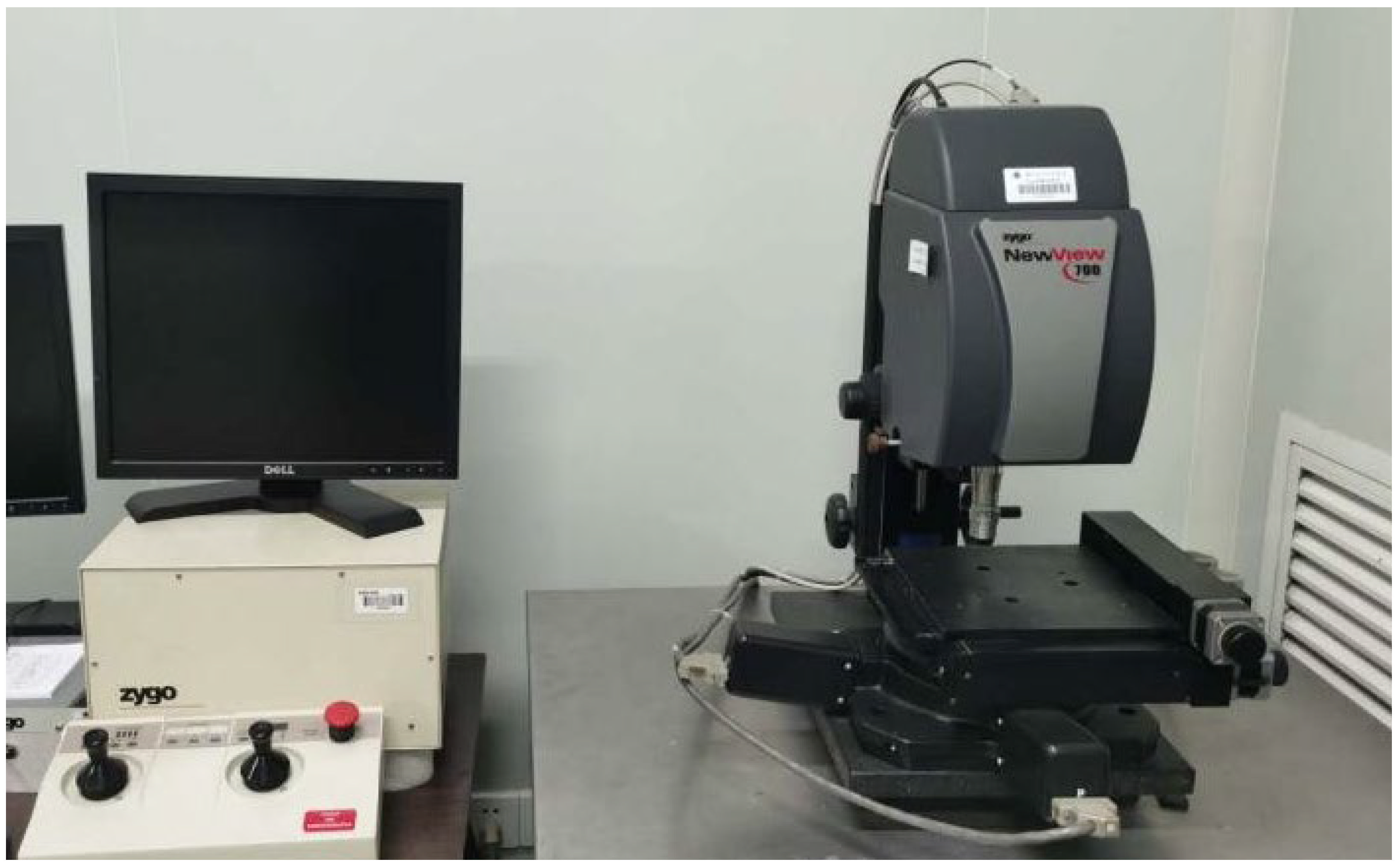
2. Equipment
3. Mechanism of Magnetorheological Polishing Related to Subsurface Damage Removal and Mid-Frequency Ripple Error Control
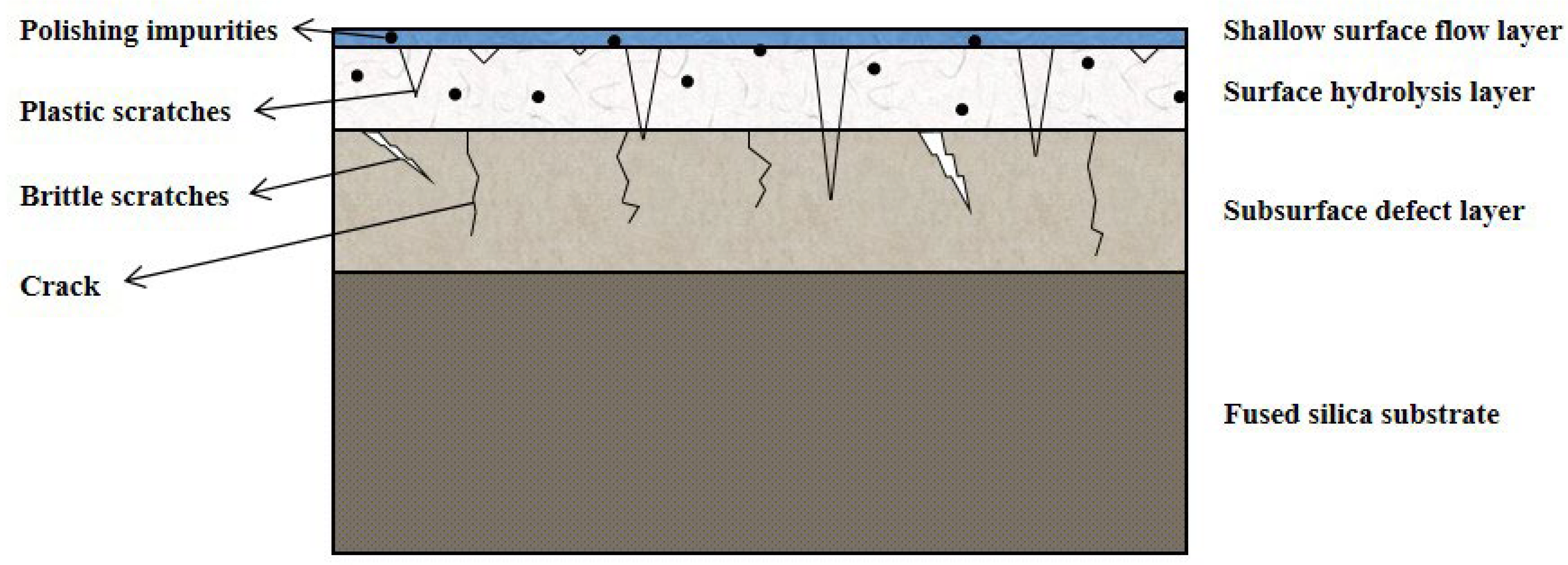
3.1. CMP Subsurface Damage Model
Subsubsection
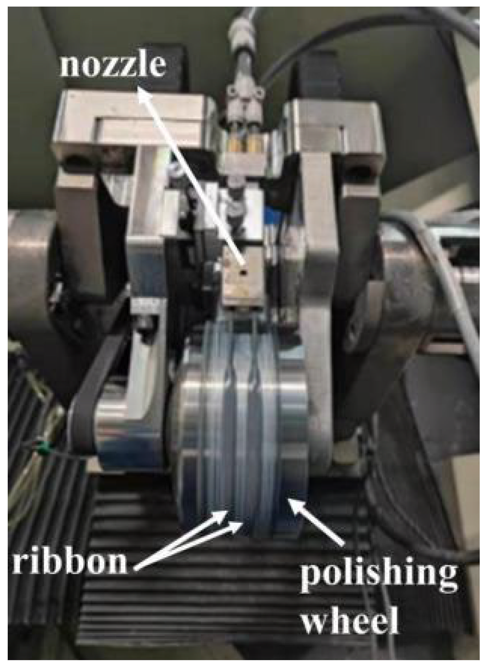
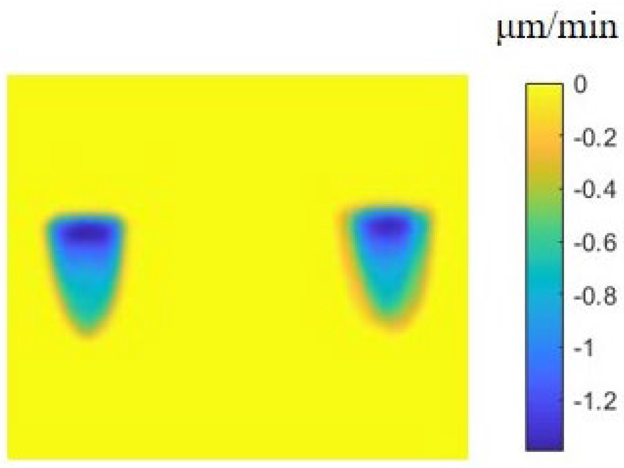
3.2. Mechanism of Magnetorheological Polishing Related to Subsurface Damage Removal
3.3. Generation and Control Mechanism of Mid-Frequency Ripple Errors in Magnetorheological Polishing
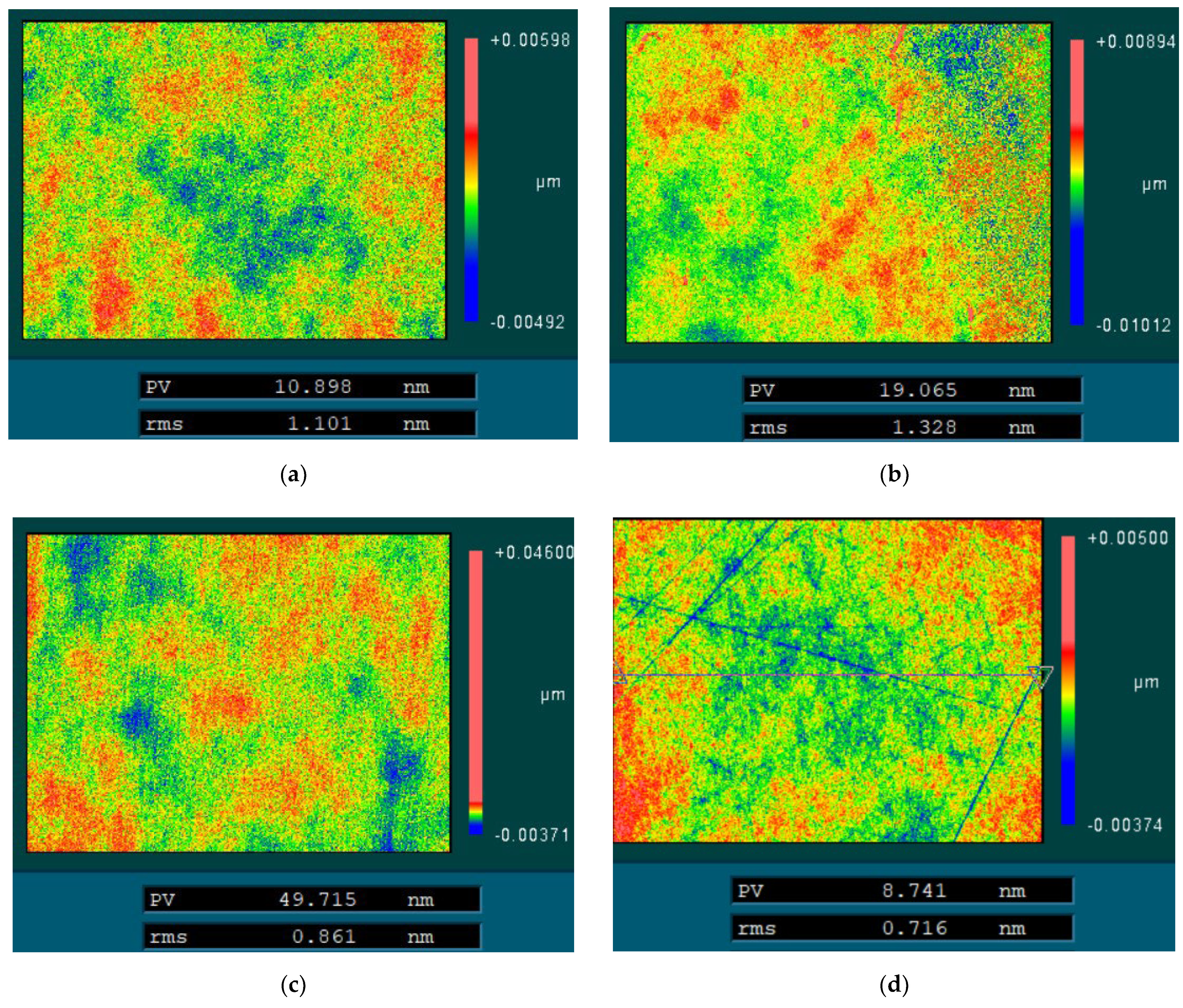
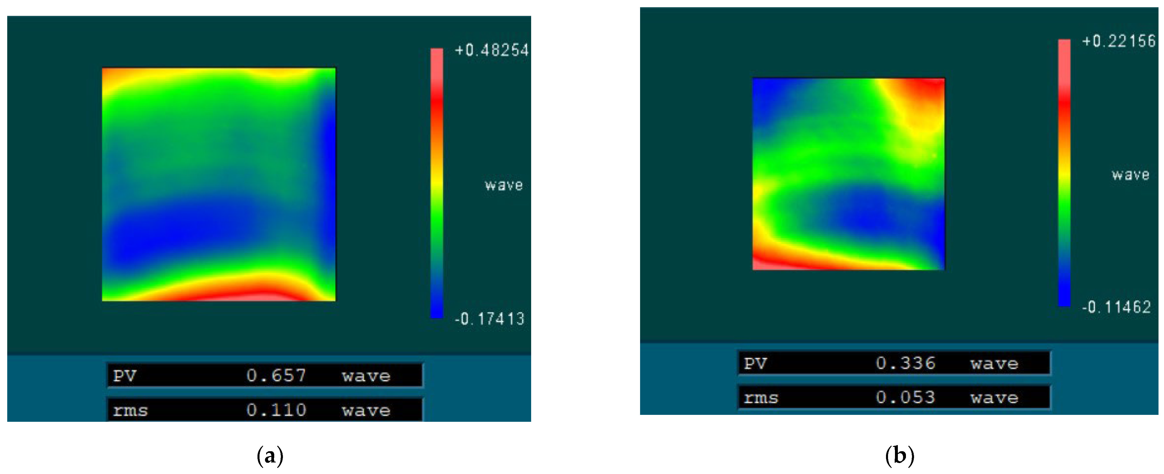
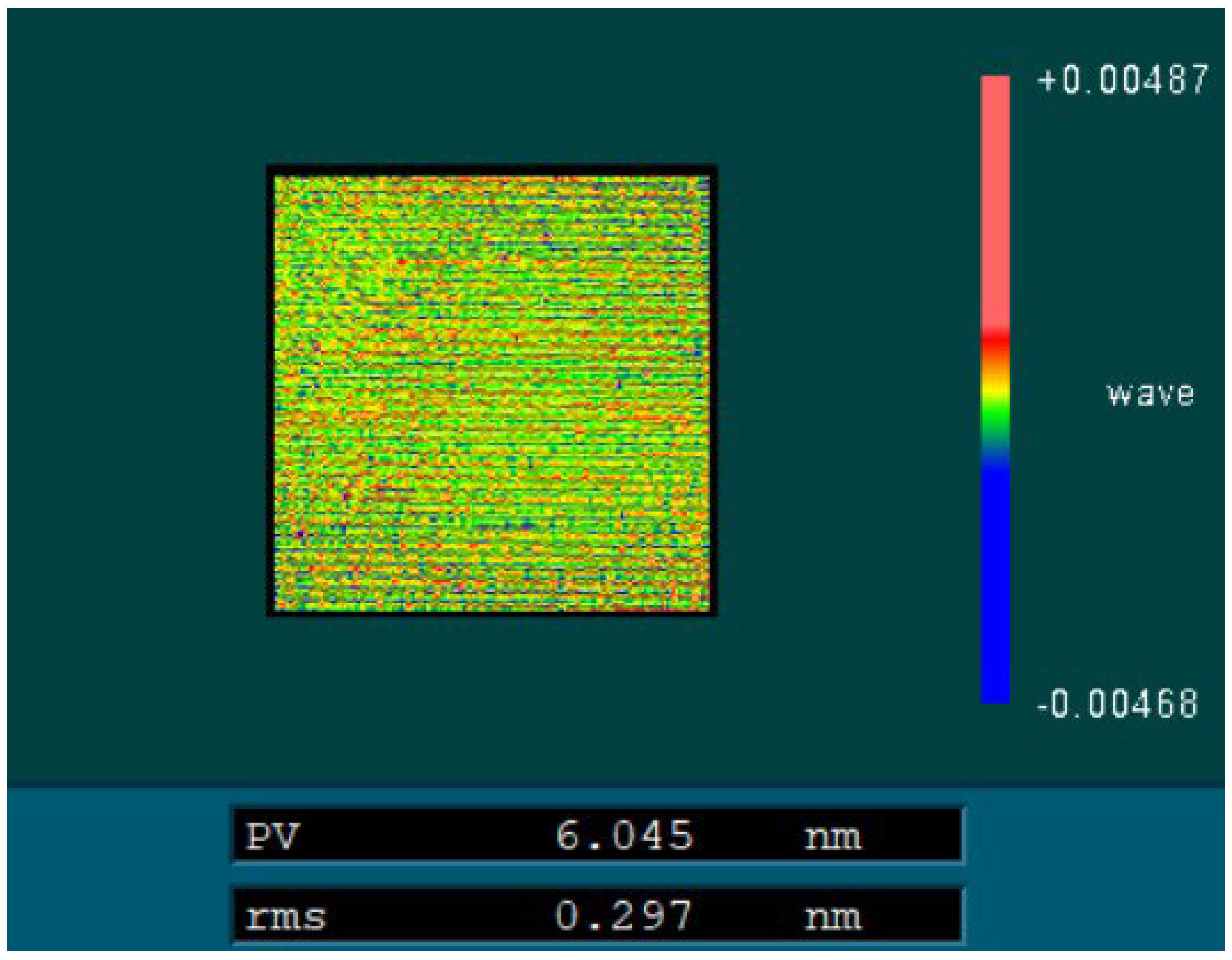
4. Damage Detection and Repair of Photomask Quartz Glass Substrates
4.1. Damage Detection of Photomask Quartz Glass Substrates
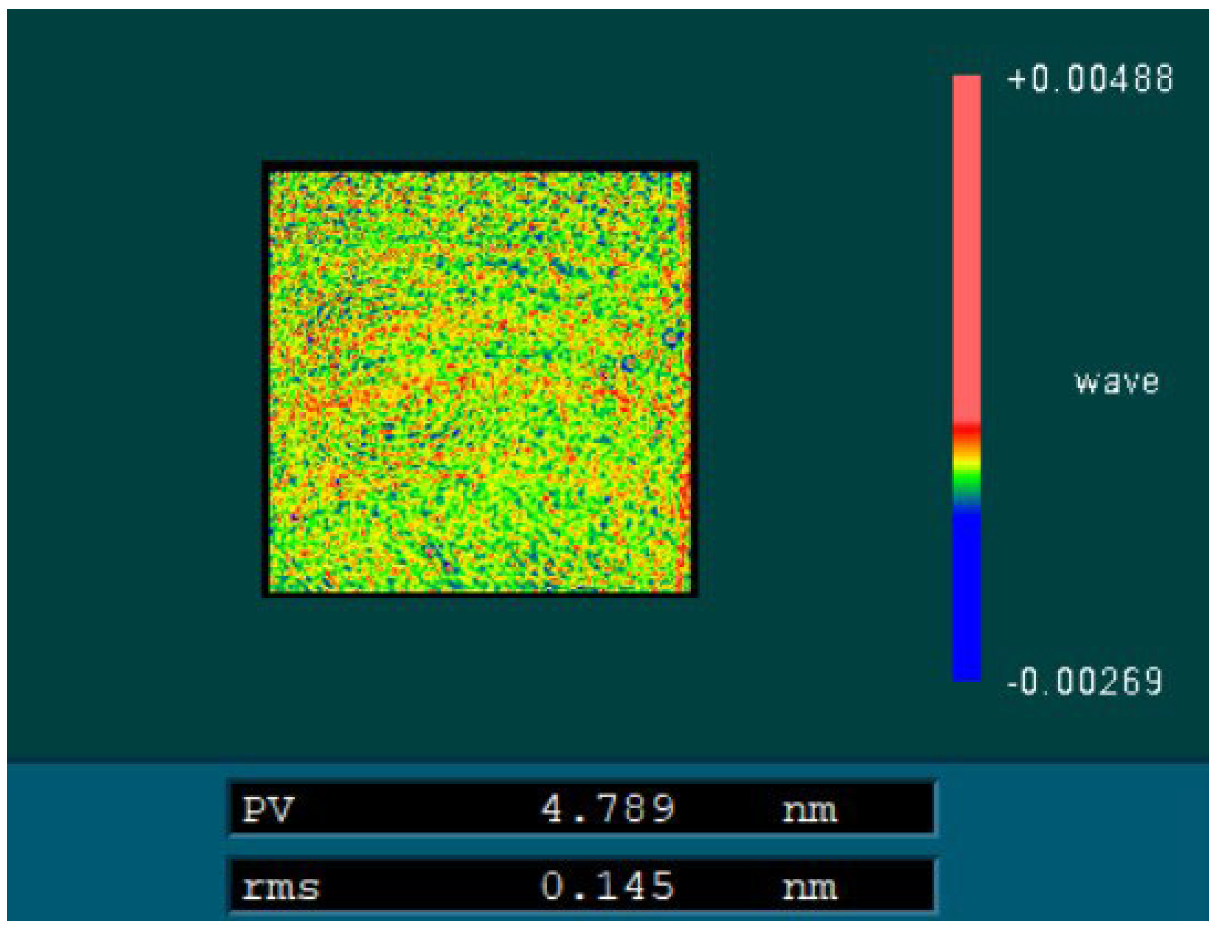
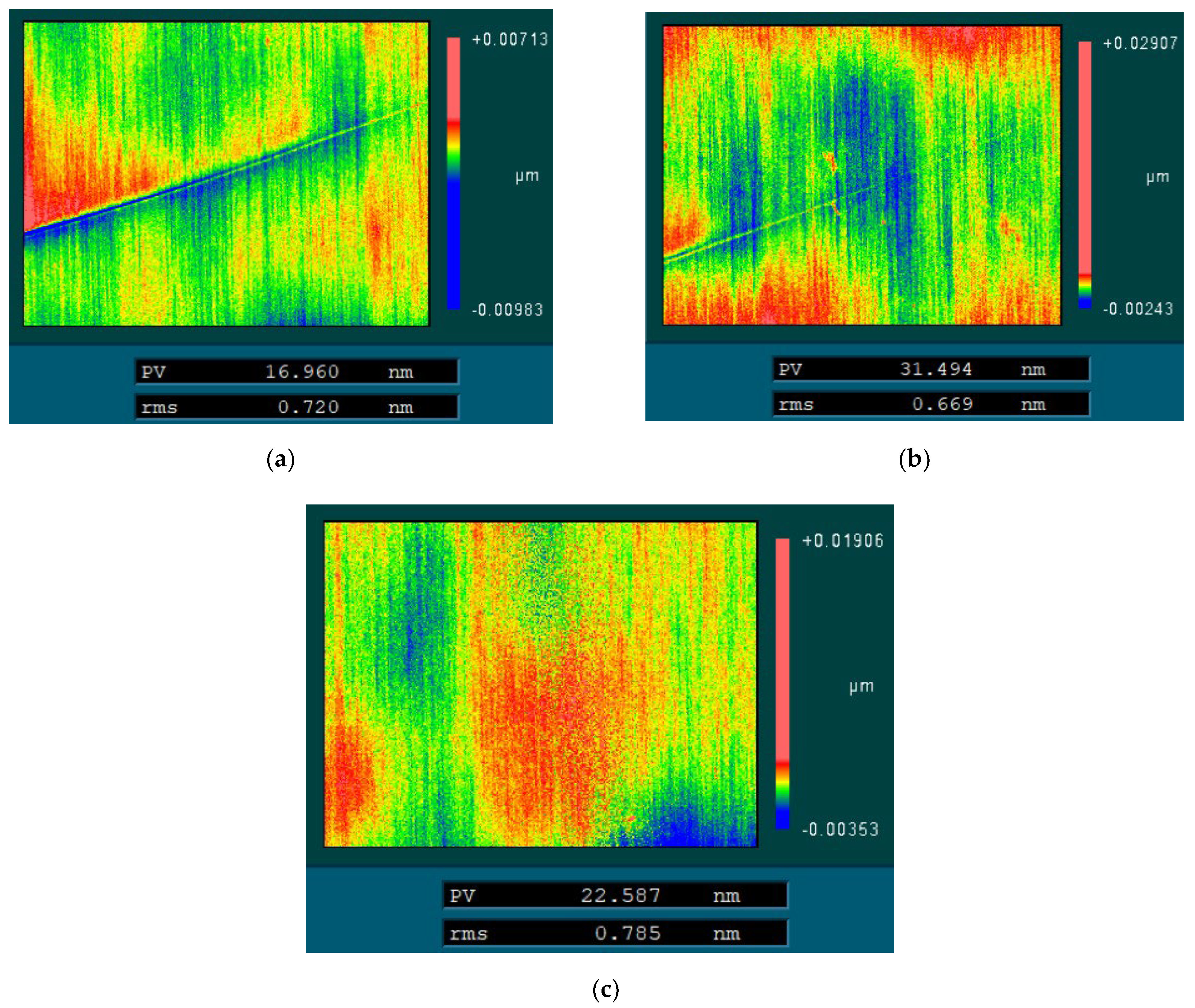
4.2. Repair and Manufacturing Process of Photomask Quartz Glass Substrates Based on Array-Type Magnetorheological Polishing Technology
5. Discussion
6. Conclusions
Author Contributions
Funding
Informed Consent Statement
Data Availability Statement
Conflicts of Interest
References
- Li, P.J. Applications of optoelectronic integrated circuit technology. Integr. Circuit Appl. 2021. [Google Scholar] [CrossRef]
- Fu, B.; Wang, Y.F.; Rao, C.D.; Xiang, Z.K.; Shao, Z.F. Low expansion quartz glass. In Proceedings of the 2015 National Glass Science and Technology Annual Conference Proceedings, Shanghai, China, 19–21 July 2015; pp. 195–198. [Google Scholar]
- Teki, R.; Kadaksham, A.J.; House, M.; Harris-Jones, J.; Ma, A.; Babu, S.V.; Hariprasad, A.; Dumas, P.; Jenkins, R.; Provine, J.; et al. Alternative smoothing techniques to mitigate EUV substrate defectivity. In Proceedings of the SPIE Advanced Lithography, San Jose, CA, USA; 2012; Volume 8322, p. 83220B. [Google Scholar] [CrossRef]
- Liu, H.; Ye, X.; Zhou, X.; Huang, J.; Wang, F.; Zhou, X.; Wu, W.; Jiang, X.; Sui, Z.; Zheng, W. Subsurface defects characterization and laser damage performance of fused silica optics during HF-etched process. Opt. Mater. 2014, 36, 855–860. [Google Scholar] [CrossRef]
- Yangyuan, W.; Jinfeng, K. Development and Challenges of Lithography for ULSI. J. Semicond. 2002, 23, 225–237. [Google Scholar] [CrossRef]
- Chen, Y.L.; Shen, J.M.; Tang, M.M. Overview of the manufacturing process of photomasked quartz glass substrates. Glass Enamel Opt. 2021, 49, 5. [Google Scholar] [CrossRef]
- Zhou, L.; Shiina, T.; Qiu, Z.; Shimizu, J.; Yamamoto, T.; Tashiro, T. Research on chemo-mechanical grinding of large size quartz glass substrate. Precis. Eng. 2009, 33, 499–504. [Google Scholar] [CrossRef]
- Qiu, Z.J.; Zhou, L.B.; Fang, F.Z. Chemical-mechanical grinding of quartz glass. Opt. Precis. Eng. 2010, 18, 8. [Google Scholar] [CrossRef]
- Xie, R. Research on high-efficiency polishing technology of photomask substrate. In Proceedings of the Young Scientists Forum 2017, Shanghai, China, 5 March 2018. [Google Scholar] [CrossRef]
- Wang, Z.J.; Wang, S.L.; Wang, C.W.; Zhang, W.Q.; Zheng, H. Chemical mechanical polishing of ultra-precision quartz glass. Micro-Nanoelectron. 2017, 54, 48–52. [Google Scholar] [CrossRef]
- Li, H.B.; Wang, C.W.; Li, H.; Zhang, W.Q.; Liu, Y.L. Chemical mechanical polishing of quartz glass based on alkaline silica-sol abrasives. Micro-Nanoelectron. 2018, 55, 8. [Google Scholar] [CrossRef]
- Zhu, Y.W.; Shen, Q.; Wang, Z.K.; Ling, S.Z.; Li, J.; Zuo, D. Exploration of the performance of polycrystalline diamond solidified abrasive grinding pads for fine grinding of quartz glass. Infrared Laser Eng. 2016, 45, 6. [Google Scholar] [CrossRef]
- Liu, D.F.; Chen, T.; Chen, G.L. Material removal mechanism of soft particle polished quartz glass. Opt. Precis. Eng. 2016, 24, 9. [Google Scholar] [CrossRef]
- Shen, X. Sampling problem for measuring surface roughness of optical elements. Opt. Instruments 1997, 19, 8. [Google Scholar] [CrossRef]
- Wang, Z. Study on the Key Technologies of Subsurface Damage Detection and Control in Optical Material Processin; National University of Defense Science and Technology: Changsha, China, 2008. [Google Scholar] [CrossRef]
- DeGroote, J.E.; Romanofsky, H.J.; Kozhinova, I.A. Polishing PMMA and other optical polymers with magnetorheological finishing. In Proceedings of the Optical Manufacturing and Testing V, SPIE’s 48th Annual Meeting, San Diego, CA, USA, 22 December 2003; Volume 5180, pp. 123–134. [Google Scholar] [CrossRef]
- Hallock, B.; Dumas, P.; Shorey, A. Recent advances in deterministic low-cost finishing of sapphire windows. In Proceedings of the SPIE-The International Society for Optical Engineering, Orlando, FL, USA, 18 May 2005; Volume 5786. [Google Scholar] [CrossRef]
- Wan, S.; Wei, C.; Hu, C.; Situ, G.; Shao, Y.; Shao, J. Novel magic angle-step state and mechanism for restraining the path ripple of magnetorheological finishing. Int. J. Mach. Tools Manuf. 2021, 161, 103673. [Google Scholar] [CrossRef]
- Wang, B.; Shi, F.; Zhang, W.; Tie, G.; Song, C.; Guo, S. Key technology research on magnetorheological finishing based on suppression of surface mid-spatial frequency ripple errors. Opt. Mater. Express 2022, 12, 3213–3224. [Google Scholar] [CrossRef]


| Item | Value |
|---|---|
| Surface shape errors | Less than 1 wave |
| Surface roughness (RMS) | Less than 2 nm |
| Cracks, ripples, pitting | Not allowed |
| Scratches | Not allowed for sizes larger than 1 µm |
| 0.031/cm2 allowed for sizes less than 1 µm |
Publisher’s Note: MDPI stays neutral with regard to jurisdictional claims in published maps and institutional affiliations. |
© 2022 by the authors. Licensee MDPI, Basel, Switzerland. This article is an open access article distributed under the terms and conditions of the Creative Commons Attribution (CC BY) license (https://creativecommons.org/licenses/by/4.0/).
Share and Cite
Wang, B.; Shi, F.; Tie, G.; Song, C.; Guo, S. An Exploration into Damage Repair and Manufacturing Technology of Photomask Glass Substrates. Appl. Sci. 2022, 12, 10010. https://doi.org/10.3390/app121910010
Wang B, Shi F, Tie G, Song C, Guo S. An Exploration into Damage Repair and Manufacturing Technology of Photomask Glass Substrates. Applied Sciences. 2022; 12(19):10010. https://doi.org/10.3390/app121910010
Chicago/Turabian StyleWang, Bo, Feng Shi, Guipeng Tie, Ci Song, and Shuangpeng Guo. 2022. "An Exploration into Damage Repair and Manufacturing Technology of Photomask Glass Substrates" Applied Sciences 12, no. 19: 10010. https://doi.org/10.3390/app121910010
APA StyleWang, B., Shi, F., Tie, G., Song, C., & Guo, S. (2022). An Exploration into Damage Repair and Manufacturing Technology of Photomask Glass Substrates. Applied Sciences, 12(19), 10010. https://doi.org/10.3390/app121910010