Abstract
This paper deals with an up-to-date topic among robotic industrial applications that require a high degree of speed, rigidity, and orientation. Currently, when technology and software applications reach a high level of performance, in various robotic industrial applications that start from certain concepts, the implementation of efficient structures has proven to be challenging. New structures such as the parallel kinematic machine (PKM) category has proven its efficiency through its structure in terms of high inertia rigidity and high speeds during processes. This paper deals with the subject of PKM-type structures in terms of the optimal design workspace of such a structure. The calculation of the workspace is considered the premise from which it starts in terms of its implementation in a robotic production line. The entire process of calculating the workspace for a given PKM structure is carried out through modern CAD applications that have specific modules in place in this direction. CATIA V5 offers the possibility through the product engineering optimizer module, simulation and calculation of different scenarios aimed at identifying the volume of the workspace for a PKM structure. In the article, we demonstrate the relations between the robot workspace and the design parameters, a method that can also be applied for other parallel structures. The method is useful for robot designers in the optimization of parallel robots with regard to the workspace by using CAD tools. Previous research in the field refers of the usage of CAD tools only for visual representation and not for optimizing the workspace, while this study and test results show that CAD tools are suitable for analyzing and optimizing the robot workspace of the 6DOF parallel robot, due to its easiness in application and fast implementation time.
1. Introduction
The scope of the current paper is to apply advanced CAD (computer-aided design) knowledge within dedicated modules, using specific tools for simulation and calculus oriented on workspace capabilities and other aspects related to the robots having PKM (parallel kinematics machines) structures. Modern manufacturing systems, in means of structures, are designed with the aim of changing their usage domain using interchangeable end effectors. Ref. [1] underlines that before implantation, all aspects regarding processes or product validation undergo tests through simulations using digital manufacturing. In many industrial applications where robotic structures are involved, characteristics regarding the ability to change position and orientation with a high precision ability are a fundamental requisite. It is known that all these robotic tasks are performed with a limitation in terms of the range of rotation or even the workspace volume [2]. Adequate equipment meets the requirements by simply making precise movements within their range of six degrees of freedom. For the first time, as it is presented in the literature, these parallel kinematics machines were used in the aircraft industry in the tires test [3,4,5,6]. In terms of the practical applications within different industries where implemented parallel robotic architectures can be found, the following tools can be underlined: parallel machine tools [7], vibration simulators with six DOF (degrees of freedom) [8] and/or motion simulators [9].
One of the key challenges within these novel PKM structures are related to their capabilities regarding the workspace. Workspace analysis of a parallel kinematic machine (PKM) using tools from a CAD optimization software offers the possibility to identify the movements, volume, and trajectories. It also indicates if there are any problems due to kinematics that need to be calculated or identified, regarding the parallel robots’ structures that focus on inverse or forward kinematics [6]. In the article, the relations between the robot workspace and the design parameters are demonstrated, a method that can be applied for other parallel structures as well. The method is useful for robot designers in the optimization of parallel robots with regard to the workspace by using CAD tools. Previous research in the field refers of the usage of CAD tools only for visual representation and not for optimizing the workspace [10], while this study and test results show that CAD tools are suitable for analyzing and optimizing the robot workspace of the 6DOF parallel robots, due to its easiness in application and fast implementation time.
The present work is focused on the functional design of a parallel kinematic machine (PKM) with six degrees of freedom (DOF). We studied and presented the aspects regarding the workspace determination via CAD techniques as well as numerical techniques.
The present study deals with the aspects mentioned above and starts with the theoretical side that is realized in the digital CAD space, before moving to the validation area by comparison with the analytical calculation level. The motivation for this research was to develop a novel PKM structure that has six DOF capable of adapting to different types of assembly process in a manufacturing plant.
2. Theoretical Aspects
2.1. Workspace Analysis Using Computer-Aided Design Applied for Parallel Kinematic Machines
Any additional study concerning the movement behavior of the robot regarding a desired job must first determine the workspace for any moving structure. Geometrical, numerical, and analytical methodologies may all be used to establish the workspace, and each method has its own set of benefits and drawbacks depending on the required workspace parameters [10].
Each technique for determining the workspace may be achieved in a variety of methods, and depending on the implementation and accuracy aspects, some approaches are easier to achieve than others. The geometrical technique entails creating the workspace volume by intersecting each kinematic chain of the PKM, resulting in the workspace volume of the PKM’s whole structure [11]. This method is simple to perform using CAD software and CAD tools, and it generates a model of the entire theoretical workspace [12,13]. One disadvantage with using this approach in the case of PKM is that some construction factors, such as limit angles for revolute joints, can be difficult to execute, and in most PKM, the moving platform, which closes all the kinematic chains, is difficult to create independently from the kinematic chains [13,14].
2.2. The Ability to Use Multiple Types of Algorithms Using Optimization Tools from CATIA V5
Modern computer-aided design programs offer multiple numerical calculation possibilities. We can use these algorithms to calculate different optimization methods, such as minimization, maximization or even target value. In the current study, we use the CAD system CATIA V5 to maximize the workspace volume of the PKM structure. The following list introduces the possible algorithms that can be implemented:
- Simulated annealing is a random-search technique, which was developed in 1983 to deal with highly nonlinear problems. The ability to avoid being stuck in local minima is SA’s main advantage over other approaches. The algorithm uses a random search, which accepts both modifications that decrease and some changes that enhance the objective function [13,14].
- For the gradient algorithm without constraints, the geometry is modified to improve its performance. Considering all the factors, it is necessary to determine the variable denoted shape sensitivity of the objective function with reference to the CAD parameters [13,14].
- The algorithm for constraints and derivative providers implements a technique for determining a viable route along which the desired function is substantially reduced. The method performs a reasonably large step length along the desired direction and utilizes the information on the optimal solution gained during the algorithm’s iterations [14].
- The gradient algorithm with constraints searches for options on a local level. It works with non-essential conditions, or those whose failure does not cause the issue of inadequacy. Constraints are often broken during the optimization algorithm in this approach [15].
- The improved harmony search method with global sharing factors based on natural number coding, the multi-objective method based on the adaptive harmony search algorithm with simulation and creation and the swarm intelligence optimization algorithm [16,17,18].
2.3. Presentation of the PKM Structure
The mechanical structure model was designed and created in CATIA V5 according to the kinematic scheme of the robot structure illustrated in Figure 1. Stiffness, accuracy, and other performance characteristics were used to develop the robotic manipulator. Because workspace determines the extent to which a robot may be used, it is a crucial concern in the design process [16,17,19,20]. In Figure 2, the 3D model of the PKM structure is displayed.
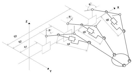
Figure 1.
The kinematic scheme of the 6DOF PKM structure.

Figure 2.
Views of the CAD model of the 6DOF PKM structure.
Increasing the workspace volume expands the robot’s capabilities by modifying the geometrical structure. The volume and form of the workspace are influenced by several geometrical design parameters, which are presented in Table 1. The product engineering optimizer module from Dassault Systems CATIA V5 seeks to maximize the workspace volume based on the constrained parameters.

Table 1.
PKM structure configuration parameters.
3. Investigation of the Workspace Volume
The major interest in the determination of the workspace volume through analytic methods is associated with the involvement of each construction parameter of the PKM structure and the analysis of the behavior of each parameter to determine if optimal singular solutions exist and if they can be determined based on multiple requirements, such as imposed workspace volume, imposed inscribed workspace volume or geometric constraints.
3.1. Analytic Determination of the PKM Workspace Volume
Considering the kinematic structure of the six DOF PKM, the three PR(RPR)RS share predefined support planes. The actuated (RPR) kinematic chain from the PR(RPR)RS kinematic chain imposes a fixed radius between the last joint of the chain, the spherical joint S, and the first revolute joint R of the chain. Depending on the total stroke of the actuated prismatic joint P from the (RPR) chain, a minimal and maximal radius are obtained, meaning that the PR(RPR)RS chain has a circular workspace, as shown in Figure 3, inside the support plane, centered in the revolute center of the first revolute joint R [20].
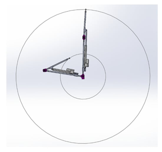
Figure 3.
Representation of the workspace of each PR(RPR)RS upper view.
Given the fact that each of the three PR(RPR)RS kinematic chains defines an individual support plane that is actuated by the first prismatic joints of the previously mentioned kinematic chains, the workspace of the PKM structure is generated by translating the resulting section, as shown in Figure 4, among the prismatic axes.
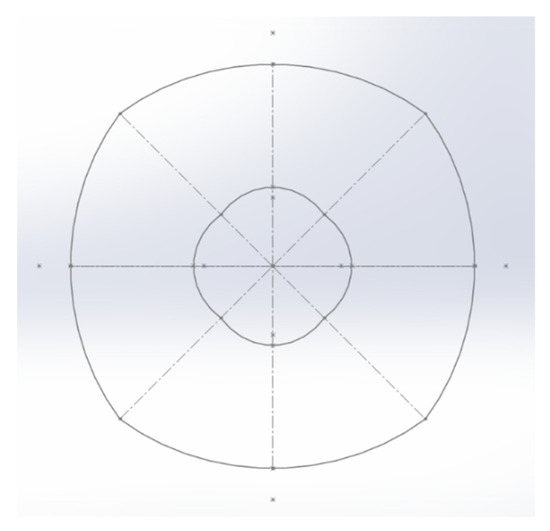
Figure 4.
Representation of the resulting section of the workspace.
The resulting section of the workspace is constructed by the intersection of four curves, as shown in Figure 5, which resulted from the projection on the normal plane to the prismatic axis of the workspaces of the three PR(RPR)RS kinematic chains. The resulting shape is constructed on the intersection of only four ellipses by considering the symmetry of the structure that has the same tilt angle for the support plane of the first and last PR(RPR)RS kinematic chains.
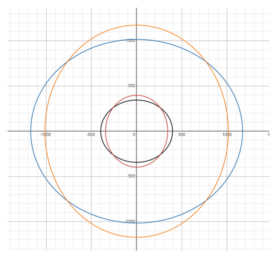
Figure 5.
Representation of the four ellipses used to construct the section of the workspace (—red, —orange, —black, —blue).
The four ellipses that determine the section are as follows:
where
- and are the minimal and maximal radiuses imposed by the (RPR) chains for the PR(RPR)RS chains;
- is the tilt angle of the first and last support plane;
- is the tilt angle of the second support plane.
For the determination of the workspace volume, it is required to determine the area of the cross section of the workspace. Considering that the section of the workspace is constructed by the intersection of four ellipses centered in the same point, the resulting geometrical shape for the section of the workspace has two-fold symmetry among the major axis of the coordinate system (OY and OZ). In the case in which the values for the tilt angles , and are equal, the cross section gains symmetry, as shown in Figure 6, among the four major axes (OY, OZ, axis Y = Z and axis Y = −Z).
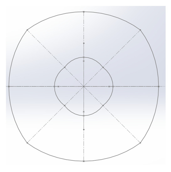
Figure 6.
Representation of the two-fold symmetry of the cross section.
Considering the symmetries of the cross section, the determination of the area of the cross section for the reachable workspace, as shown in Figure 7, was implemented by using the formula for the area of an ellipse sector.
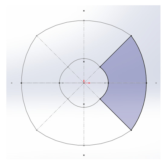
Figure 7.
Representation of reachable workspace area.
In this case, the area of the shaded region from the previous figure is as follows:
where is the angle resulting from the axis defined by the intersection points of and , respectively, and and .
The value of is
Therefore, the formula for the area of the cross section of the reachable workspace is as follows:
For the determination of the volume of the reachable workspace for the 6DOF PKM, the integration of the cross-section area among the OX axis was used, taking into consideration the bounding planes defined by the first and last PR(RPR)RS kinematic chains. The geometry of the reachable workspace volume is two-fold symmetric, meaning that the whole workspace volume can be split into quarters, which aids the demonstration.
By evaluating only the quarter of the reachable workspace volume, as shown in Figure 8, by integration among the OX axis, the remaining area of the cross section in the regions bounded by the planes defined by the first and last PR(RPR)RS kinematic chains needs to be expressed in terms of the stroke among the OX axes.
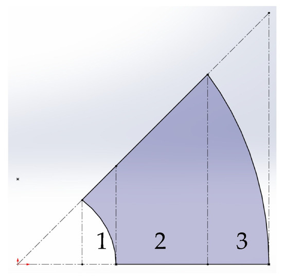
Figure 8.
Representation of the half cross section ant the integration sectors.
Given the behavior of the sectioning plane, the following relations represent the variable area in terms of stroke among the OX axis:
where
where
The volume of the reachable workspace is as follows:
where
3.2. Results of the Numerical Analysis
The main goal of this paper is to compare CAD optimization features for the generation of the reachable workspace of the 6DOF PKM and this requires the determination of the behavior of the volume, with respect to the tilt angles and , as shown in Figure 9. Due to the complexity of the previous equations, explicit differentiation is not an option and the previous relations for the volume of the reachable workspace were implemented in MathWorks MATLAB and the variation in the volume was analyzed, with respect to the tilt angles, by using numerical methods.
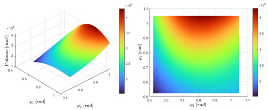
Figure 9.
Representation of the volume distribution based on the values of tilt angles and .
It was observed that the volume tends to be at its maximum around and is the maximal value of the interval of the analysis, which, in this case, is . If the analysis interval is extended up to , the optimal value for will be , considering the behavior of the second PR(RPR)RS kinematic chain.
4. Implementation Based on CAD Optimization Tools
As presented in the previous sections, the PKM structure was designed and created in Catia V5 using design tools from the part, assembly and DMU Kinematics modules. The simulation process was also accomplished with the help of the CAD software Catia V5, because of the multiple algorithms offered in the module of product engineering optimizer.
In the optimizer module, we selected the following parameters with the aim of maximizing the workspace volume. The optimization parameter was determined with the smart volume function, which needs a single attribute of the modelled volume. The free parameters were as follows: the inf. range equal to 30°, the sup. range equal to 60° and the incrementation value was set to 1 degree for a more optimal result. The maximum number of updates was set to 450 and a safety parameter for the maximum number of updates was set to be equal to 50. The optimization was performed on a computer with the following hardware characteristics: CPU 3.30 GHz, memory 16 gigabytes [17].
The optimization was based on the simulated annealing algorithm as it is very stable and offers accurate results even in complex problems, as presented in the work of multiple researchers with a raw form or even a derived version [21]. The working principle is similar with the one used in metallurgy; more precisely, the process involves increasing the main parameter to the highest limit, then slowly decreasing it until it reaches the initial value [22,23,24,25,26,27]. The main parameter used for the optimization was the inclination φ1, which is known to be equal to φ3. Based on the selected algorithm, it was possible to obtain an extensive range, of which the most important values are presented in Table 2.

Table 2.
Workspace volume (mm3) results from product engineering optimizer module (CATIA V5).
The main results summarized in Table 2 are extracted in ascending order of angle value φ1 to expose the maximum and minimum volume limits as a relation with the tilt angle. The simulation for the PKM structure starts from the initial value of 30° and almost immediately reaches the upper limit of 60°, which follows a period of descent, until it stabilizes by itself [22,23,24,25,26,27]. The results have been post-processed to present them as clearly as possible and to draw attention to the maximum value obtained for the workspace volume. As is shown in Figure 10, the volume obtained through the module of product engineering optimizer had the maximum value of 427,839,567 mm3, when the tilt angle φ1 reached the value of 47.1531 deg.
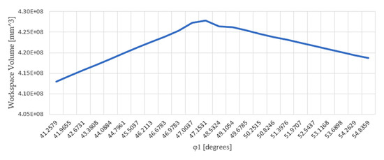
Figure 10.
Graphical representation of the workspace volume optimization results from CATIA V5.
5. Conclusions
This paper presents the study that was developed to identify the working volume and its behavior based on the construction parameters of a 6-DOF parallel kinematic machine, using an analytic method and CAD optimization tools. In the article, the relations between the robot workspace and the design parameters were demonstrated, a method that can also be applied for other parallel structures. The method is useful for robot designers in the optimization of parallel robots with regard to the workspace by using CAD tools. Previous research in the field refers to the usage of CAD tools only for visual representation and not for optimizing the workspace, while this study and test results show that CAD tools are suitable for analyzing and optimizing the robot workspace of the 6DOF parallel robot, due to its easiness in application and fast time implementation time.
The result obtained from the comparison of the analytic method and the CAD optimization method showed identical behavior and almost identical results; however, due to the complexity of the analytic mathematical expressions and the way in which CatiaV5 computes volumes of bodies with complex surfaces, the optimal values obtained are approximates. The most significant results showed that there is a discrepancy between the importance of construction parameters in the case of overall reachable volume and kinematic constraints. It was determined that in order to maximize the working volume, one of the construction parameters tends to reach values at which the kinematic structure will lose degrees of freedom. Further research is proposed regarding this aspect to improve the optimization processes for the determination of the optimal working volume regarding kinematic constrains and performance indices for the PKM 6DOF structure.
Author Contributions
Conceptualization, S.-D.S. and A.O.; methodology, S.-D.S., F.P. and A.O.; software, A.O. and P.C.; validation, A.O.; formal analysis, S.-D.S. and F.P.; investigation, P.C.; resources, A.O.; data curation, A.O.; writing—original draft preparation, F.P., A.O. and P.C.; writing—review and editing, S.-D.S., F.P., A.O. and P.C.; visualization, A.O.; supervision, S.-D.S. and F.P. All authors have read and agreed to the published version of the manuscript.
Funding
This research received no external funding.
Institutional Review Board Statement
Not applicable.
Informed Consent Statement
Not applicable.
Data Availability Statement
Not applicable.
Conflicts of Interest
The authors declare no conflict of interest.
References
- Mourtzis, D. Simulation in the design and operation of manufacturing systems: State of the art and new trends. Int. J. Prod. Res. 2019, 58, 1927–1949. [Google Scholar] [CrossRef]
- Palpacelli, M.C.; Carbonari, L.; Palmieri, G.; D’Anca, F.; Landini, E.; Giorgi, G. Functional Design of a 6-DOF Platform for Micro-Positioning. Robotics 2020, 9, 99. [Google Scholar] [CrossRef]
- Ahn, C.; Seo, T.; Kim, J.; Kim, T.-W. High-tilt parallel positioning mechanism development and cutter path simulation for laser micro-machining. Comput. Aided Des. 2007, 39, 218–228. [Google Scholar] [CrossRef]
- Shimizu, Y.; Peng, Y.; Kaneko, J.; Azuma, T.; Ito, S.; Gao, W.; Lu, T.-F. Design and construction of the motion mechanism of an XY micro-stage for precision positioning. Sens. Actuators A Phys. 2013, 201, 395–406. [Google Scholar] [CrossRef]
- Zhang, D.; Li, X.; Ni, M.; Li, P.; Dong, L.; Rui, D.; Zhang, J. Design of 6 degree-of-freedom micro-positioning mechanism for optical elements. In Proceedings of the IEEE 13th International Conference on Electronic Measurement & Instruments (ICEMI), Yangzhou, China, 20–22 October 2017. [Google Scholar]
- Han, H.; Zhang, Y.; Zhang, H.; Han, C.; Li, A.; Xu, Z. Kinematic Analysis and Performance Test of a 6-DOF Parallel Platform with Dense Ball Shafting as a Revolute Joint. Appl. Sci. 2021, 11, 6268. [Google Scholar] [CrossRef]
- Zhang, D.; Lang, S.Y.T. Stiffness modeling for a class of reconfigurable PKMs with three to five degrees of freedom. J. Manuf. Syst. 2004, 23, 316–327. [Google Scholar] [CrossRef]
- Yang, J.; Xu, Z.; Wu, Q.; Zhu, M.; He, S.; Qin, C. Dynamic modeling and control of a 6-DOF micro-vibration simulator. Mech. Mach. Theory 2016, 104, 350–369. [Google Scholar] [CrossRef]
- Shiga, Y.; Tanaka, Y.; Goto, H.; Takeda, H. Design of a six degree-of-freedom tripod parallel mechanism for flight simulators. Int. J. Autom. Technol. 2011, 5, 715–721. [Google Scholar] [CrossRef]
- Chaudhury, A.; Ghosal, A. Determination of Workspace Volume of Parallel Manipulators Using Monte Carlo Method. In Computational Kinematics; Springer: Cham, Switzerland, 2018. [Google Scholar] [CrossRef]
- Gokul, S.N.; Shrivatsan, R.; Venkatasubramanian, K.; Anjan, K.D. Deter-mination of Constant Orientation Workspace of a Stewart Platform by Geometrical Method. Appl. Mech. Mater. 2015, 813–814, 997–1001. [Google Scholar] [CrossRef]
- Busetti, F. Simulated Annealing Overview. ResearchGate. 2001. Available online: https://www.researchgate.net/publication/238690391_Simulated_annealing_overview (accessed on 10 September 2022).
- Leblond, T.; Froment, P.; Nazelle, P.; Sellakh, R.; Serré, P.; Chevallier, G. Gradient-based Optimization of Parameterized CAD Geometries. In Proceedings of the 11th World Congress on Structural and Multidisciplinary Optimization, Sydney, Australia, 7–12 June 2015. [Google Scholar]
- Lucidi, S.; Sciandrone, M. A Derivative-Free Algorithm for Bound Constrained Optimization. Comput. Optim. Appl. Kluwer Acad. Publ. 2002, 21, 119–142. [Google Scholar] [CrossRef]
- Barbarosie, C.; Lopes, S.; Toader, A.M. A gradient-type algorithm for constrained optimization with applications to multi-objective optimization of auxetic materials. arXiv 2018, arXiv:1711.04863. [Google Scholar]
- Arrouk, K.A.; Bouzgarrou, B.C.; Gogu, G. CAD based techniques for workspace analysis and representation of the 3CRS parallel manipulator. In Proceedings of the 19th International Workshop on Robotics in Alpe-Adria-Danube Region, Budapest, Hungary, 24–26 June 2010. [Google Scholar]
- Liu, L.; Huo, J. Apple Image Segmentation Model Based on R Component with Swarm Intelligence Optimization Algorithm. Int. J. Perform. Eng. 2018, 14, 1149–1160. [Google Scholar] [CrossRef][Green Version]
- Liu, L.; Huo, J. Apple Image Recognition Multi-Objective Method Based on the Adaptive Harmony Search Algorithm with Simulation and Creation. Information 2018, 9, 180. [Google Scholar] [CrossRef]
- Liu, L.; Huo, J.; Xue, F.; Dai, Y. Harmony Search Method with Global Sharing Factor Based on Natural Number Coding for Vehicle Routing Problem. Information 2020, 11, 86. [Google Scholar] [CrossRef]
- Arrouk, K.A.; Bouzgarrou, B.C.; Stan, S.D.; Gogu, G. CAD Based Design Optimization of Planar Parallel Manipulators. In Solid State Phenomena; Trans Tech Publications, Ltd.: Bach, Switzerland, 2010. [Google Scholar] [CrossRef]
- Stan, S.-D.; Maties, V.; Balan, R. Workspace Optimal Design of a 2 DOF Micro Parallel Robot Using Genetic Algorithms and Simulated Annealing Optimization Methods. In Proceedings of the 2007 International Conference on Mechatronics and Automation, Harbin, China, 5–8 August 2007; pp. 1108–1113. [Google Scholar] [CrossRef]
- Popișter, F.; Oarcea, A.; Stan, S.D.; Trifan, C.V. Workspace Analysis of a Novel Parallel Kinematic Machine with 6 Degrees of Freedom. In Advances in Manufacturing III. Manufacturing 2022. Lecture Notes in Mechanical Engineering; Gapiński, B., Ciszak, O., Ivanov, V., Eds.; Springer: Cham, Switzerland, 2022. [Google Scholar] [CrossRef]
- Oarcea, A.; Popister, F.; Stan, S.-D.; Cobilean, V. Comparative study of CAD optimization features for the workspace of 3DOF Parallel Robot. In Proceedings of the 2021 9th International Conference on Modern Power Systems (MPS), Cluj-Napoca, Romania, 16–17 June 2021; pp. 1–6. [Google Scholar] [CrossRef]
- Heragu, S.S. Experimental-analysis of simulated annealing-based algorithms for the layout problem. Eur. J. Oper. Res. 1992, 57, 190–202. [Google Scholar] [CrossRef]
- Fabian, V. Simulated annealing simulated. Comput. Math. Appl. 1997, 33, 81–94. [Google Scholar] [CrossRef]
- Musharavati, F.; Hamouda, A.S.M. Enhanced simulated-annealing-based algorithms and their applications to process planning in reconfigurable manufacturing systems. Adv. Eng. Softw. 2012, 45, 80–90. [Google Scholar] [CrossRef]
- Aboulissane, B.; El Haiek, D.; El Bakkali, L.; El Bahaoui, J. On The Workspace Optimization of Parallel Robots Based on CAD Approach. Procedia Manuf. 2019, 32, 1085–1092, ISSN 23519789. [Google Scholar] [CrossRef]
Publisher’s Note: MDPI stays neutral with regard to jurisdictional claims in published maps and institutional affiliations. |
© 2022 by the authors. Licensee MDPI, Basel, Switzerland. This article is an open access article distributed under the terms and conditions of the Creative Commons Attribution (CC BY) license (https://creativecommons.org/licenses/by/4.0/).