Article

Establishing the True Dynamic Bending Moment of Propeller Shaft Using a Single Bridge of Strain Gauge

1
Division of Marine System Engineering, Korea Maritime and Ocean University, Busan 49112, Korea
2
Interdisciplinary Major of Maritime AI Convergence, Korea Maritime and Ocean University, Busan 49112, Korea
3
Division of Marine Information Technology, Korea Maritime and Ocean University, Busan 49112, Korea
4
Machinery Team of Technical Division, Korean Register, Busan 46762, Korea
5
Division of Marine Engineering, Mokpo National Maritime University, Mokpo 58628, Korea
*
Author to whom correspondence should be addressed.
Appl. Sci. 2022, 12(18), 9235; https://doi.org/10.3390/app12189235
Submission received: 29 July 2022 / Revised: 8 September 2022 / Accepted: 9 September 2022 / Published: 15 September 2022
(This article belongs to the Special Issue Ship Structures: Design Loads and Reliability Assessment)

Abstract

:

Featured Application

This research presents the novelty in establishing the true dynamic bending moment using only one bridge of strain gauge. This is achieved by using the actual measured bending stress combined with phase lag stress at an angle of 90 degrees.

Abstract

The measurement of shaft bending (whirling) moment can be performed via a telemetry system including strain gauges which can obtain the bending stress. By using a single bridge of strain gauge, it was possible to obtain only the nominal bending moment. However, in case of the propeller shaft vibration measurement, the true dynamic bending moment is needed to evaluate the effect of propeller forces on the stability of the bearings. To deal with this, typically two bridges of strain gauge at 90 degrees are needed. This research presents a novel reliability assessment method in establishing the true dynamic bending moment using only one bridge of strain gauge. This is achieved by using the actual bending stress measured by strain gauge combined with its own phase lag stress at an angle of 90 degrees. To validate this technique, the experiments were performed under the rapid turning transient states during a sea trial of a 50,000 DWT oil/chemical tanker. As a result, great fluctuations in propeller force were detected, resulting in a non-uniform oil film in the bearings. The displacement sensor was also installed and confirmed the established true dynamic bending moment.

1. Introduction

Shaft alignment is influenced by hull deformation, engine output, propeller force and propeller eccentric thrust. These factors lead to an unevenly distributed load on the bearings, and subsequently, they increase the risk of damage [1]. It is necessary to ensure the distances between the bearings and to set the specific height for each bearing with respect to the fair curve alignment theory [2,3,4]. Therefore, the load can be shared evenly for every bearing [5]. Even so, the after-stern tube bearing damage can still occur under sudden changes in the stern water flow field, such as rapid ship turning [6,7,8,9,10,11,12]. It is known that the major cause of rapid ship turning is the unstable behavior of the shaft due to the change in eccentric thrust of the propeller. This is a result of the change in the countercurrent distribution at the rear of the stern, which temporarily applies excessive load to the stern tube bearing.
In the cases of newly built ships, it has become more difficult to ensure the stability of the shafting system [13,14,15] due to the current green and eco-friendly trend in marine transportation. Accordingly, the low-speed, ultra-long stroke engine has been widely applied to enhance ship operation efficiency [16,17]. To maintain the ship’s speed at a lower engine speed, the propeller diameter is slightly increased compared to the previous design. This design change not only increases the propeller mass but also the load and pressure rise, which are applied to the after-stern tube bearing in terms of shaft alignment, making it easier to achieve the safety tolerance recognized by the manufacturer.
In this context, this study concerns the bending moment behavior of the propeller shaft in a medium-range tanker of 50,000 deadweight tonnage (DWT). Due to the friction of the ship’s hull moving in water while sailing, a boundary layer of water is created around the ship and moves at the same speed as the hull. The thickness of this layer increases from the fore-to-aft of the ship. The displacement of water by the ship also induces wake waves. Under rapid turning conditions, the quick change in direction of the ship’s heading causes a sudden change in the wake field [18]. This was determined by the non-uniform water flow in the propeller working area behind the ship’s hull. Many studies have been conducted in the wake field. The study by Mikkelsen et al. [19] used computational fluid dynamics (CFD) analysis to investigate the nominal wake fields of a container ship in regular waves with wavelength equal to the ship length in five different headings. The result reveals significant fluctuation in the nominal wake fraction in wave conditions. Sprenger et al. [20] created a framework for more than 1300 different model tests for three ship hulls of different geometry and hydrodynamic characteristics that focuses on the added resistance and drift forces, propulsion and rudder force tests in waves and the assessment of maneuverability of ships in waves. A series of measurements carried out by Valanto and Hong [21] showed that all ship motion components have a clear effect on the additional wave resistance. Wu et al. [22] used the wake field data of multiple two-dimensional planes obtained by scanning particle image velocimetry (PIV) measurements to reconstruct the three-dimensional, three-component (3D-3C) wake field. Shuai Sun et al. [23] conducted computational studies using the Reynolds Averaged Navier–Stokes (RANS) method on viscous wake fields and the propulsion performance of a four-screw ship. Their results provided the behavior of vortices and turbulent structures in the hull. The wake field caused fluctuation amplitudes of the loads on the propeller. Another study was conducted by Sadat-Hosseini and his team [24]. They performed experiments and computations for a containership in calm water and regular waves. They found that that a significant fluctuation in the wake field can affect propeller/engine performance. As a result, the propeller forces fluctuated, and that changed the behavior of the bending moment as well as the stability of the propulsion shafting system. In the case ship of this study, several related works have already been published [25], but there is still an issue that needs to be clarified.
It is well-known that the measurement of the bending moment and shaft alignment can be performed via the bending stress obtained by strain gauges with telemetry systems. This technique does not require disassembling the shaft line. It was introduced early by Grant [26], Forrest and Labasky [27]. This method can be conducted while the ship is afloat, as opposed to more traditional methods which often require dry docking of the ship. Cdr Amit Batra et al. [28] carried out propulsion shaft alignment measurements on an afloat warship. Zhang et al. [29] identified the specific bearing load based on a three-section strain gauge. A study by Avgouleas et al. [30] used strain gauges to verify the satisfactory alignment of the entire shafting system as well as the accurate gearbox positioning of a high-speed naval craft. There are many other studies that also used this method [31,32,33,34]. By the same manner, in the previous work on this case ship [25], the authors determined the nominal bending moment though a single bridge of strain gauge. This affects the position of the shaft in the bearing as well as the pressure distribution of the lubrication film. It is noted that the nominal bending moment has only one value which does not change during a shaft rotation. It is related to the quasi-static condition. In fact, the propeller force varies at every angle of rotation. This fluctuation leads to a continuously changing oil film pressure in the bearing, which repeats itself for every rotation of the shaft, resulting in the instability of the bearings. It is related to the dynamic condition which is not accessible by the nominal bending moment only. Establishing the true dynamic bending moment is needed to evaluate the effect of propeller forces on the bearings as well as whole propulsion system. Ordinarily, two bridges of strain gauge at 90 degrees are needed. This research explores the novelty in establishing the true dynamic bending moment using only one bridge of strain gauge. This new technique provides reliable results compared to the conventional method requiring double bridges. It helps to simplify the equipment and, therefore, to reduce the measurement cost. The experiments were carried out under the rapid turning transient states of the target ship as port turn and starboard turn, which significantly affected the working conditions of the propeller. A half-bridge of strain gauge was installed at the close vicinity of forward stern tube seal box as a means to establish the true dynamic bending moment. The final purpose was to investigate the effect of the propeller force on the bearings and propulsion system because of the sudden change in the stern’s wake-field during rapid turning. Displacement measurement was also performed simultaneously to confirm the accuracy of this technical method.

2. Methodology

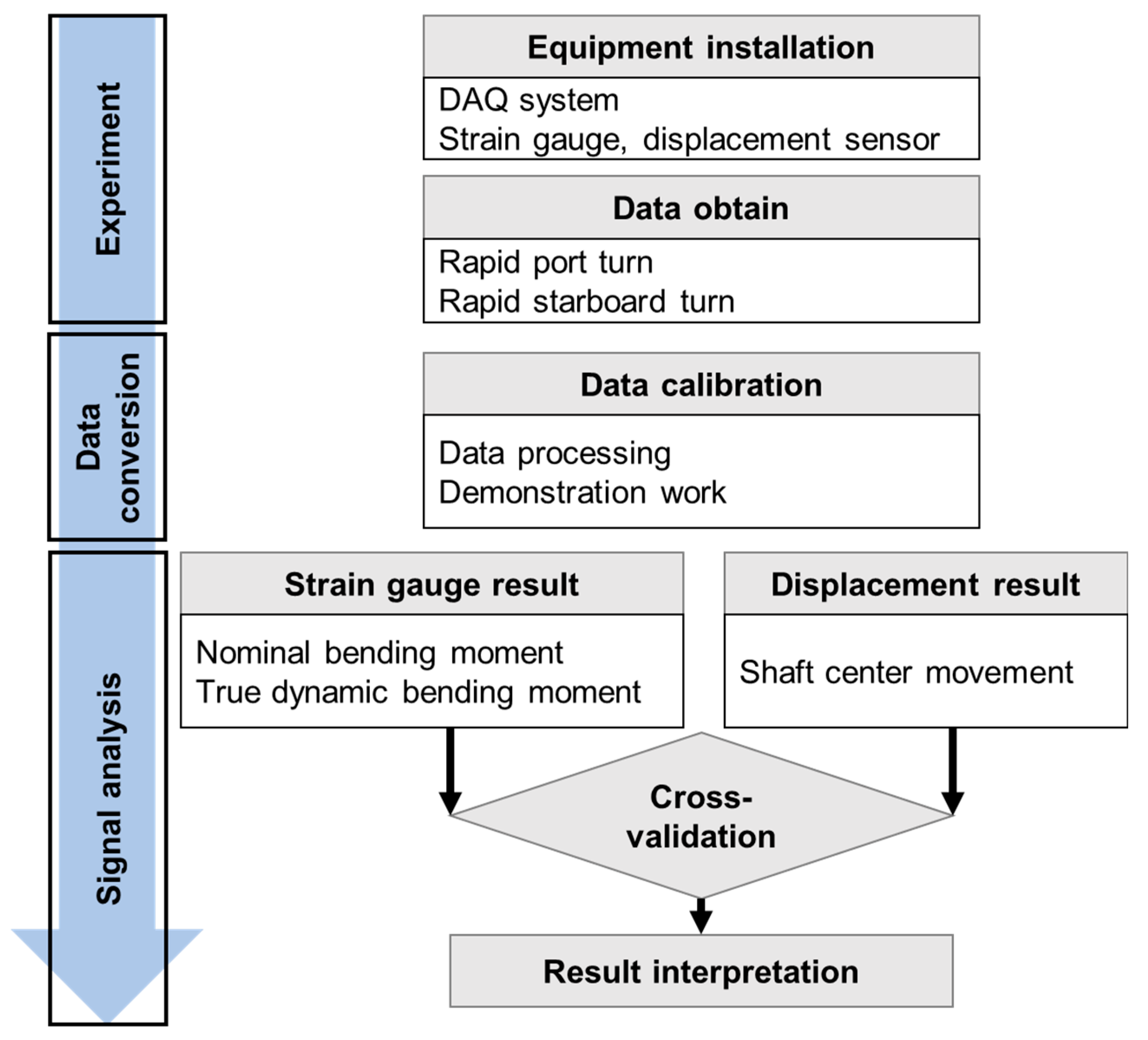
2.1. Research Approach

The research approach in this case study is based on measurement as described in the flowchart in Figure 1. Accordingly, the measurement sensors including the strain gauge and displacement sensor were installed to obtain the status of the propulsion system. Through the data acquisition (DAQ) system, all data were acquired simultaneously and then recorded during experiments. The strain gauge signals were analyzed to establish the nominal and the true dynamic bending moments. These would be compared to the shaft center movements to validate the accuracy of the research method.

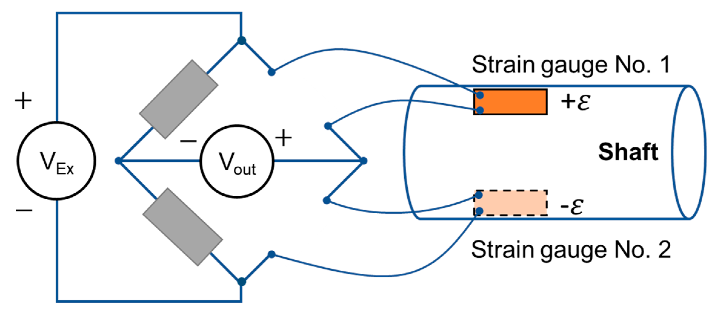
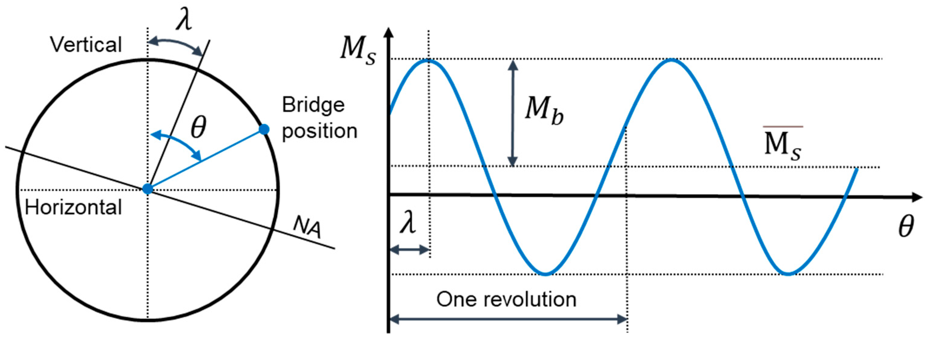
2.2. Bending Moment Measurement Using Strain Gauges

The strain gauge method is a high-accuracy technique recommended by ISO International Standard for bending moment measurement [35]. The most common strain gauge wiring configuration is in the form of a Wheatstone bridge [36,37,38]. Depending on the measurement task, the bridge layout can be configurated as full-bridge, half-bridge or quarter-bridge. In this measurement, the half-bridge configuration was applied with two active strain gauges positioned on the same shaft cross-section at 180 degrees to each other, as described in Figure 2. This can compensate for the temperature effect and exclude the axial vibrations (only the bending moment is measured). The position of the strain gauge bridge is defined as the position of strain gauge No. 1.
The bending moment of the shaft at the position of the strain gauge bridge (local bending moment) can be obtained from the bending strain as follows [27]:
M s = E ε I d 2 × 10 6
where:
M s = local bending moment (kN∙m);
ε = measured strain by strain gauge bridge (m/m);
E = Young’s Modulus (MPa);
I = second moment of shaft cross-section (mm4);
d = diameter of the shaft cross-section (mm).
In the case of the solid shaft:
I = π d 4 64  
Therefore:
M s = E ε π d 3 32 × 10 6  
The local bending moment for a full revolution is depicted in Figure 3. Accordingly, the local bending moment at any angle can be determined by:
M s = M b c o s θ λ + M s ¯  
where:
M b = nominal bending moment (kN∙m);
θ = angle of rotation related to vertical direction (degree);
λ = angle between normal to neutral axis (NA) and vertical direction or bending angle (degree);
M s ¯ = mean value of local bending for one revolution (kN∙m).
Figure 3. Local bending moment measured at every rotating angle position of strain gauge.
Applsci 12 09235 g003
Under the assumption that the propeller forces are the same for all propeller blades, the mean value of local bending, M s ¯ , is constant with the variation in the shaft speed. It can be zeroed if the zero calibration is performed when the bridge is located at the horizontal position. To calculate the nominal bending moment, only the zero-to-peak value is needed:
M b = M s   m a x M s   m i n 2
The bending angle, λ , is determined by the travel from the upper vertical to the point of maximum local bending moment. This technique is very simple and precise for the pure sinusoid or approximate sinusoid of the static bending moment.

2.3. Bending Moment Calculation Using Frequency Domain

The above method using the zero-to-peak value is very common and makes it convenient to obtain the bending moment such as during static conditions when slow turning. However, its accuracy is lower in the case of combined vibration as a dynamic test. As explained earlier, the bending moment of the propeller shaft during ship operation is influenced by many factors such as hull deformation, engine output, propeller force and propeller eccentric thrust. Therefore, the peak values of local bending moments may be not at normal to NA, leading to slightly erroneous results of bending angle, λ . As shown in Figure 3 and Equation (4), the nominal bending moment during one revolution is determined by the zero-to-peak value, which is the amplitude of the first-order vibration, and the bending angle can be found as the first-order phase angle. To do this, frequency domain analysis must be performed, and the Fourier transformation is the key mathematical tool here.
In this method, the tachometer is required to determine the shaft revolution. The tacho-pulse marks the beginning and end of a revolution when the strain gauge bridge is located at the upper vertical position. The measured local bending moment in time domain is divided into each complete revolution for analysis. Next, the Fourier transformation is performed to parametrize the time domain data in terms of frequency. The fast Fourier transform (FFT) is recommended to speed up the computation. Next, the signal is converted and represented in the frequency domain, and only the first-order frequency is concerned for the nominal bending amplitude and bending angle with accuracy.

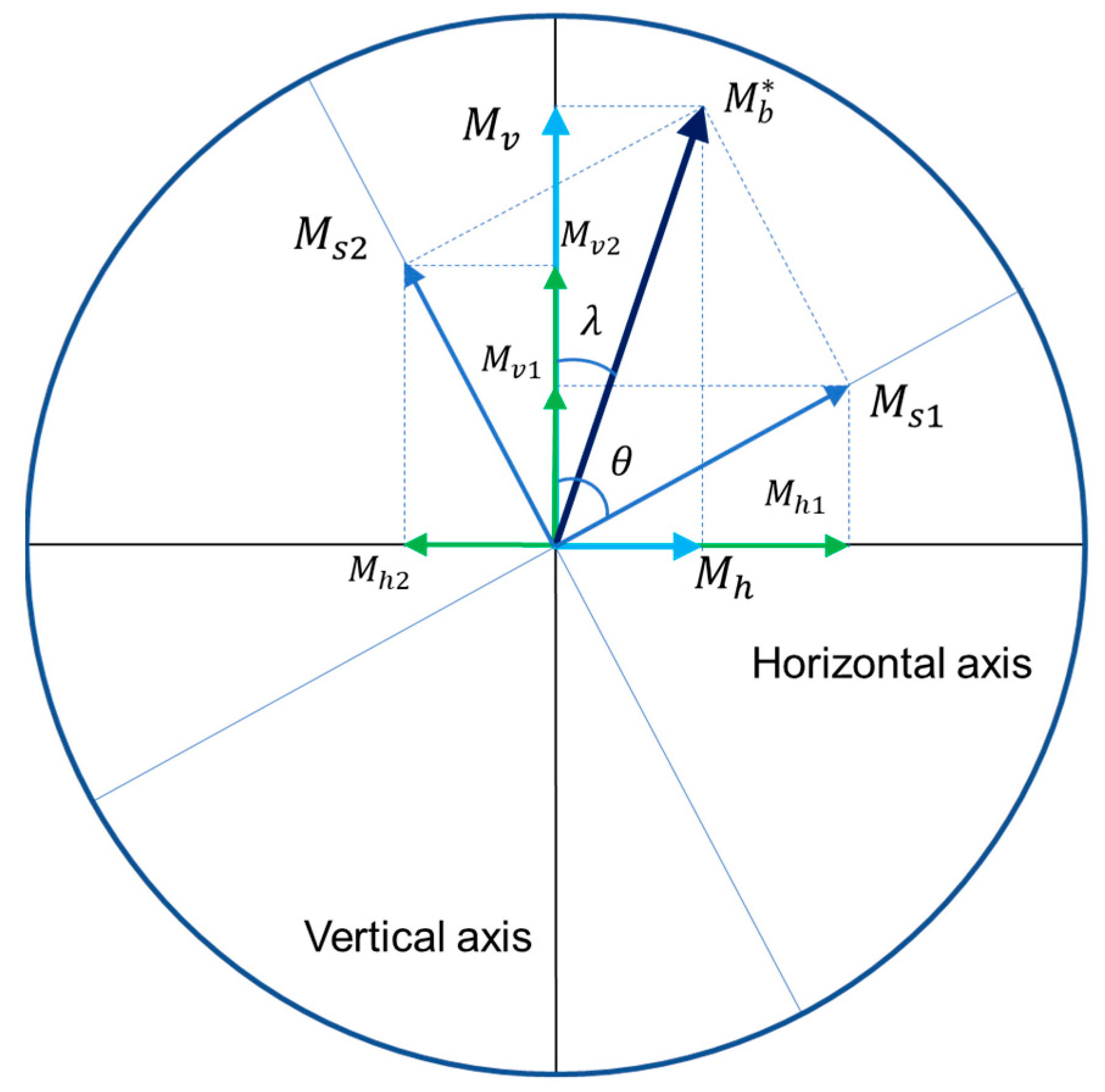
2.4. True Dynamic Bending Moment Establishment

Direct reading of the strain gauge results will be presented in the rotating coordinate system. Two of the above methods can only obtain the nominal bending moment. This affects the position of the shaft in the bearing as well as the pressure distribution of the lubrication film. However, the vibration component of the propeller forces leads to a continuously changing pressure distribution in the bearing, which repeats itself for every rotation of shaft. To identify the propeller-induced forces of the vertical and horizontal position for every rotating angle, it is necessary to evaluate the true dynamic bending moment. Typically, this requires two bridges of strain gauge (S1 and S2) positioned 90 degrees to each other. When the bridge S1 is located at the angle θ related to the upper vertical axis, then the bridge S2 is located at the angle of ( θ 90 ° ). The local bending moments measured by these bridges are denoted by M s 1 and M s 2 , respectively, as described in Figure 4.
The true dynamic bending moment of shaft, M b * , is obtained by:
M b * = M s 1 + M s 2
We have:
M b * = M v + M h
M s 1 = M v 1 + M h 1
M s 2 = M v 2 + M h 2
Substituting the Equations (7)–(9) into Equation (6), the vertical and horizontal bending moments are determined as follows:
M h = M h 1 + M h 2
M v = M v 1 + M v 2
or:
M h = M s 1 sin θ + M s 2 sin θ 90 ° = M s 1 sin θ M s 2 cos θ
M v = M s 1 cos θ + M s 2 cos θ 90 ° = M s 1 cos θ + M s 2 sin θ
The true dynamic bending angle is determined by
λ = t a n 1 M h M v if   M v 0
or:
λ = t a n 1 M h M v + 180 ° if   M v < 0
In the case that only one bridge of strain gauge, S1, is installed, a new measurement technique is required to obtain the true dynamic bending moment. The propeller has four blades, the true dynamic bending moment includes the nominal bending (static) and the fourth-order bending moment fluctuation (dynamic) due to the propeller force. The nominal bending moment does not change during a shaft rotation. Assuming that the propeller force distribution by all blades are even, the main fluctuation of the fourth-order repeats its period after every 90 ° . Here is the key point of this research. Consider the state where the bridge S1 was at angle ( θ 90 ° ) and the local bending moment was measured as M s 1 . In the current state, S1 is at angle θ , and the local bending moment now is M s 1 . The bridge S2 (if available) now is at angle ( θ 90 ° ) and obtains M s 2 . The local bending moment repeats after shaft rotation every 90 ° , meaning that M s 2 = M s 1 (both are measured at the same position of angle but 90 degrees out of phase). Thus, bridge S2 can be omitted, and the true dynamic bending moment is established using the actual bending stress, M s 1 , combined with its own phase lag stress at an angle of 90 degrees, M s 1 . This research presents the novelty of establishing the true dynamic bending moment using a single strain gauge bridge, simplifying the equipment and therefore reducing the measurement cost.

3. Experiment and Results

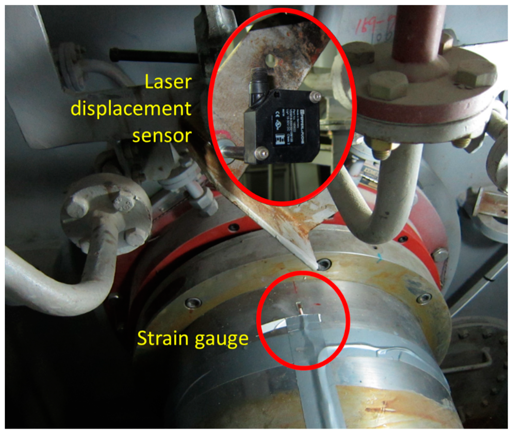
3.1. Experiment Setup

Table 1 describes the main specification of the case ship and propulsion system for bending moment measurement. A half-bridge of strain gauge was installed in close vicinity to the forward stern tube seal box. The strain gauges are of type WFLA-3 with a 3 mm gauge length produced by the Tokyo Measuring Instrument Lab. The telemetry transmitter model is T24-AR of KYMA. To measure the radial displacement of the propeller shaft, the laser displacement sensor type VDM18-300/32/105/122 of PEPPERL+FUCHS was installed in the vertical direction on the same shaft, cross-sessional with the strain gauges, as shown in Figure 5. The accuracy of the laser is ±0.2 mm. The displacement measurement can be used to cross-check the behavior of the bending moment obtained by the strain gauge measurement.
The experiment followed International Convention for the Safety of Life at Sea, SOLAS II-1/29/3 (rudder test), released by the International Maritime Organization (IMO). The purpose of this study is to investigate the effect of the propeller force on bearings and propulsion system because of the sudden change in the stern’s wake-field during rapid turning. The testing procedure is described in Figure 6 in the full laden condition for both port and starboard turning tests as follows:
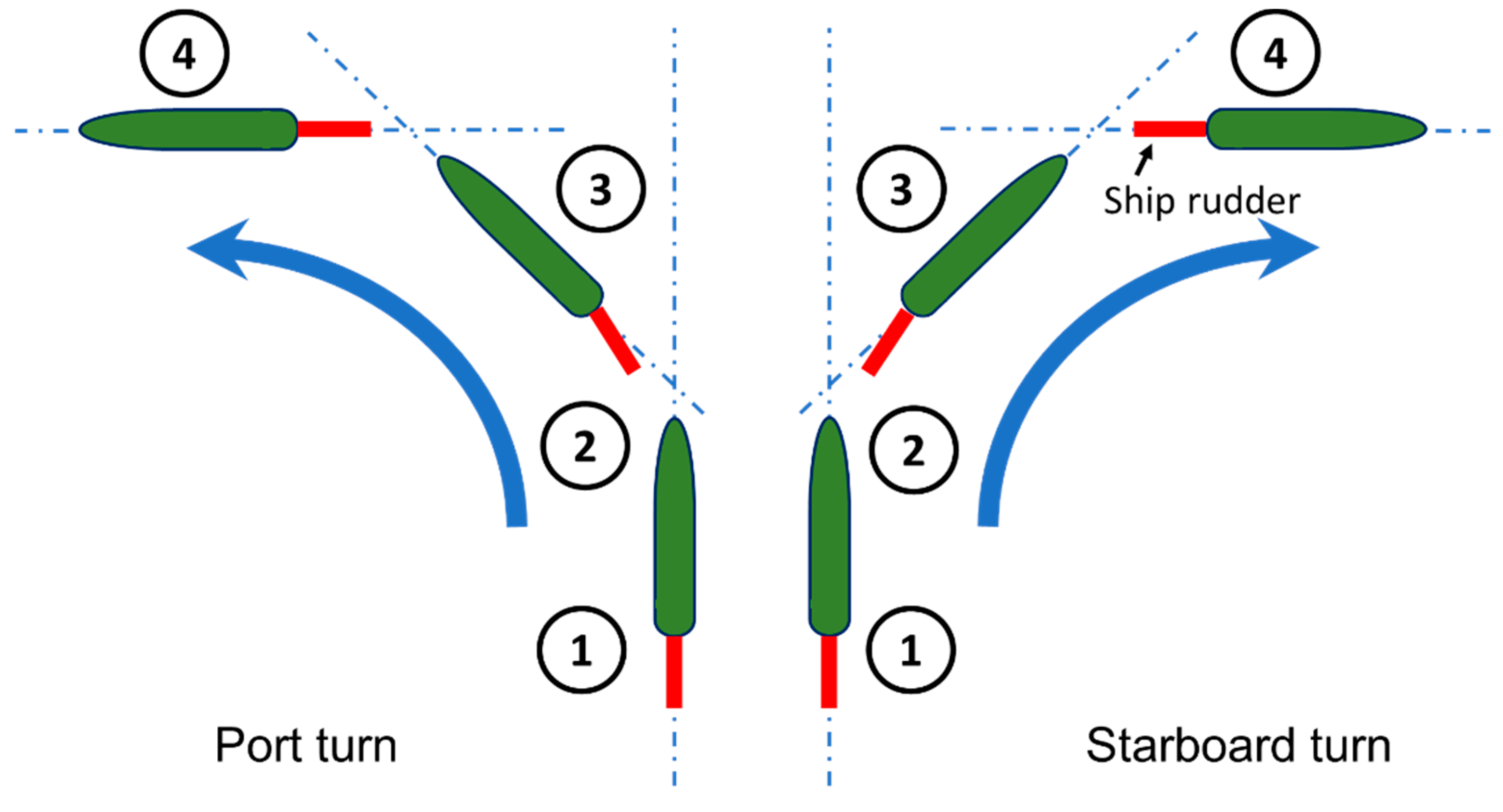
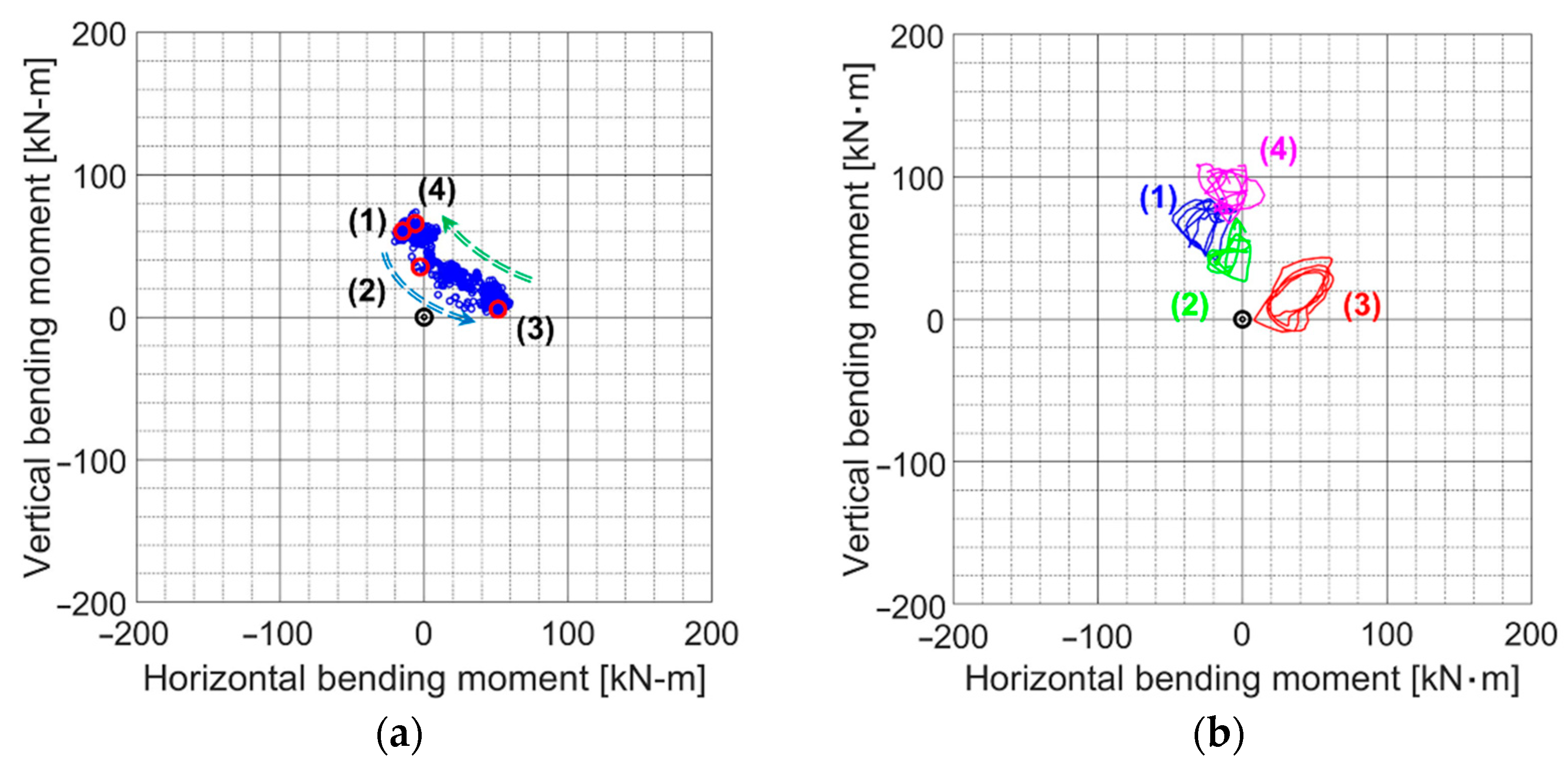
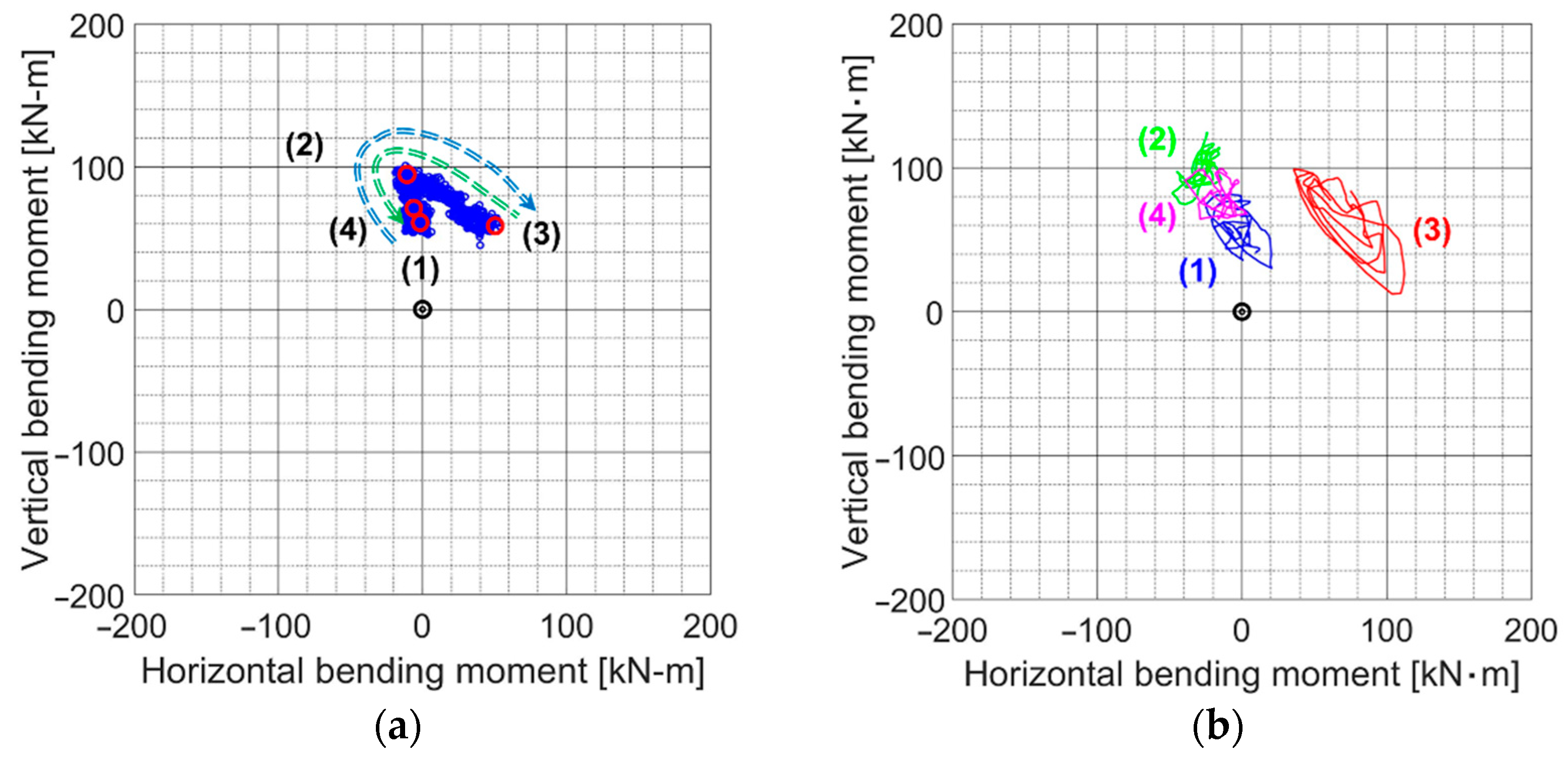
  • Stage (1): Rudder angle 0 degrees: NCR straight going (begin);
  • Stage (2): Rudder angle changes from 0 to 12 degrees (port or starboard);
  • Stage (3): Rudder angle 12 degrees: ship’s heading is gradually changing;
  • Stage (4): Rudder angle 0 degrees: NCR straight going (end).

3.2. Results and Discussion

By using the actual bending stress combined with the phase lag stress, the true dynamic bending moments during every full shaft revolution were taken in both horizontal and vertical direction then illustrated as in Figure 7. The displacement movement measured by the laser sensor, described in Figure 7c, confirms the accuracy of the establishing method. Accordingly, in the vertical direction, the waveforms of the bending moment and displacement are similar to each other.
Figure 8, Figure 9 and Figure 10 depict the true dynamic behaviors of the propeller shaft for the whole process of the rapid port turning test. The displacement movement, described in Figure 10, once again confirms the behavior of the bending moment. Additionally, the nominal bending moment was also achieved by using the Fourier transformation for every revolution. There is only one nominal bending moment value that can be obtained for each full revolution. This can be also called the static or average of bending moment. As shown in Figure 8 and Figure 9, the values of the nominal bending moment obtained by the conventional method were the same as the mean values (or average values) of the established true dynamic bending moment. By plotting all the vertical and horizontal positions of the nominal bending moments in a graph, we can demonstrate the trajectory of the bending moment, as shown in Figure 11a. At each stage of the test procedure, one revolution was selected to draw the orbit plot of the true dynamic bending moment, as in Figure 11b. Similarly, the shaft bending moment behavior during a rapid starboard turn was analyzed and then depicted in Figure 11.
According to the tendency of nominal values, the bending moment of the propeller shaft had moved downward counterclockwise at the beginning (Stage (1) to Stage (3)) and then returned in the same trajectory at the end (Stage (3) to Stage (4)) of the port turn, as described in Figure 11a. In the event of a starboard turn, the bending moment had moved in the opposite direction, upward clockwise at the beginning, and then retuned at the end, as in Figure 12a. This phenomenon was due to the influence of the propeller’s eccentric thrust on the propeller shaft. The propeller worked like a seesaw: when this end moved up, the other end moved down [25]. The eccentric thrust in the case of the port turn is opposite to that of the static load of the propeller’s weight. This results in the reduction in load on the after-stern tube bearing (ASTB) [39]. The opposite effect during the starboard turn causes the ASTB to go in and out of stable condition.
The shaft behavior can be evaluated in more detail during a revolution by the true dynamic bending moment, which shows the dynamic movement of the shaft. As depicted in Figure 11b and Figure 12b, the moment orbit in Stage (3) is larger than the others for both tests. This means the propeller force fluctuation was greater than the previous stage. The phenomenon occurred more clearly in the case of the starboard turn. This results in a non-uniform oil film in the bearings. This instability can be referred to as an oil whirl or even an oil whip regarding the intensity of the turbulence [40,41,42,43]. An oil whirl occurs due to the external fluctuating forces such as those generated by the propeller blades. It is transmitted to the bearings, which then creates the imbalance in the hydraulic forces on the oil film. When the oil whirl becomes intense, it becomes an oil whip, which possibly leads to bearing wear and premature failure. In the case ship in this study, the fluctuation behavior was not significant. However, the early detection of signs of bearing instability is essential for the safe operation of bearings.

4. Conclusions

This research presents the novelty in establishing the true dynamic bending moment using only one bridge of strain gauge instead of double bridges. This technique was applied in the experiments on a 50,000 DWT tanker under the rapid turning transient states, such as port turns and starboard turns, that significantly affected the working conditions of propeller. The following is the summary of what the experiment achieved:
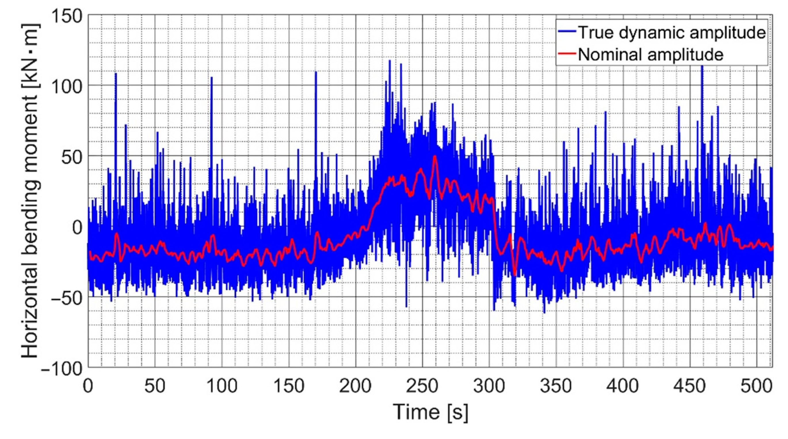
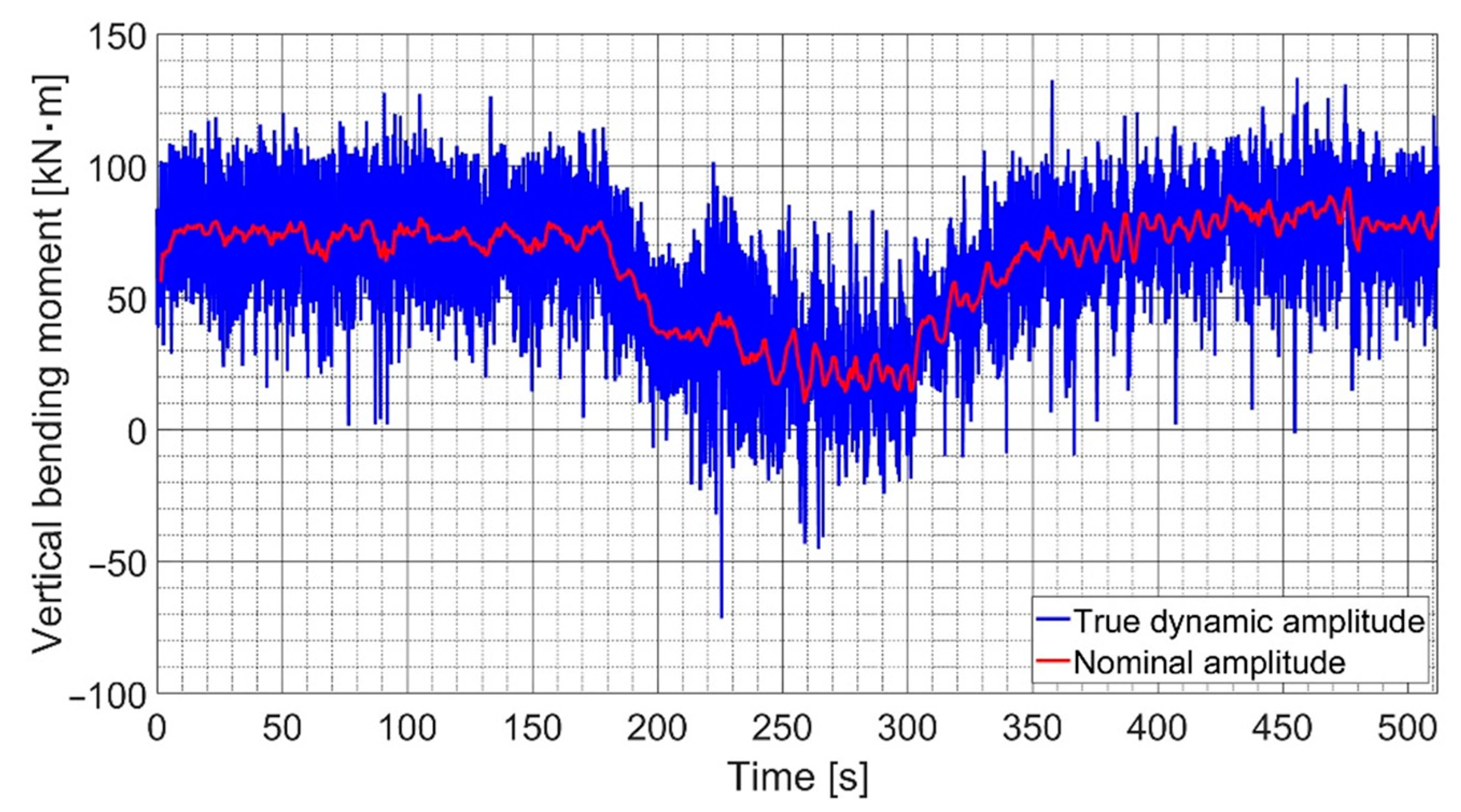
  • The strain gauge method is a high-precision technique for measuring the bending moment vibration. The nominal bending moment during one revolution can be determined by the zero-to-peak value in the time domain or the first-order vibration in the frequency domain. To identify the effect of forces induced by the propeller on the vertical and horizontal positions for each angle of rotation, it is recommended to evaluate the true dynamic bending moment by installing two strain gauge bridges positioned 90 degrees to each other.
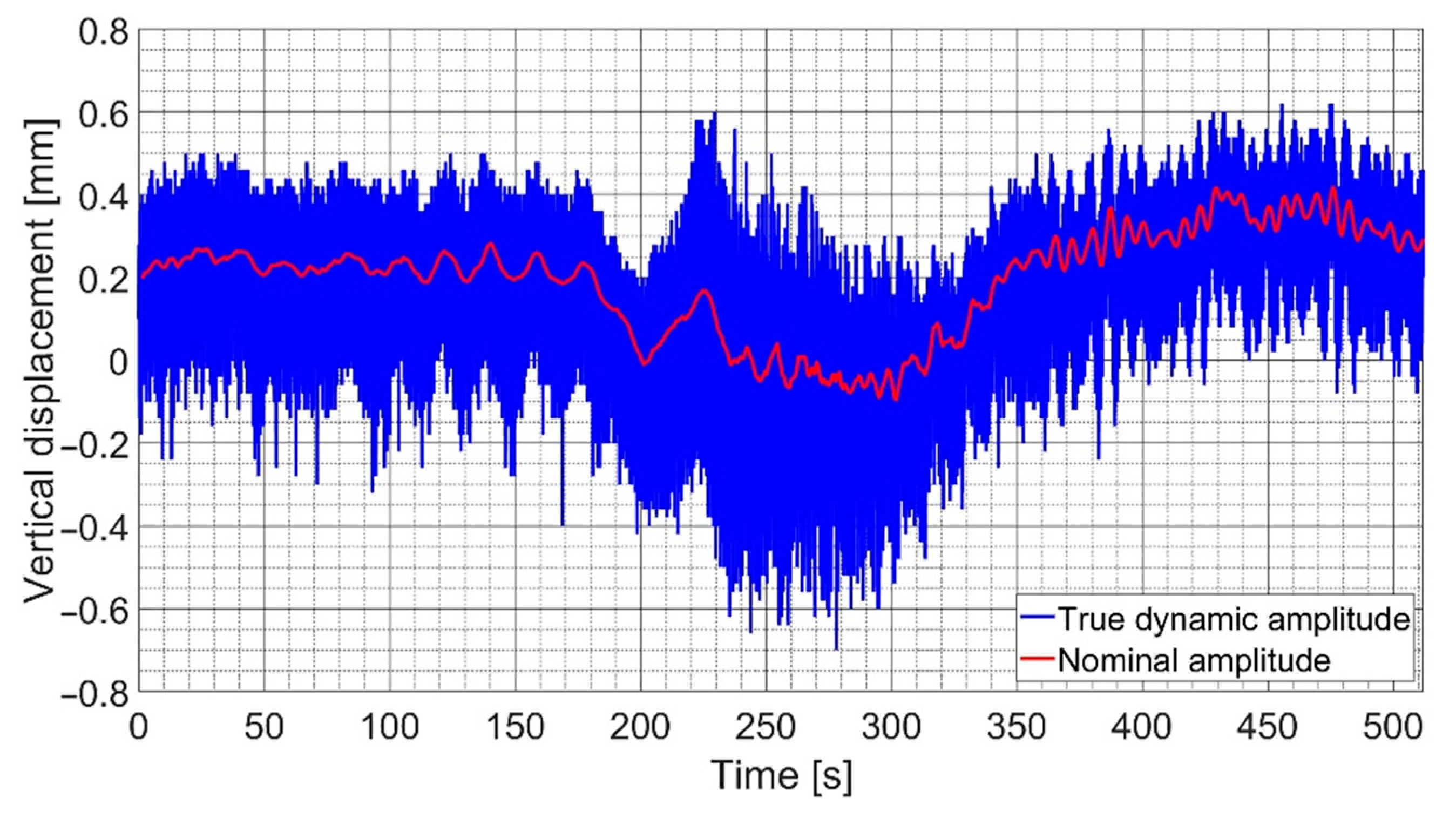
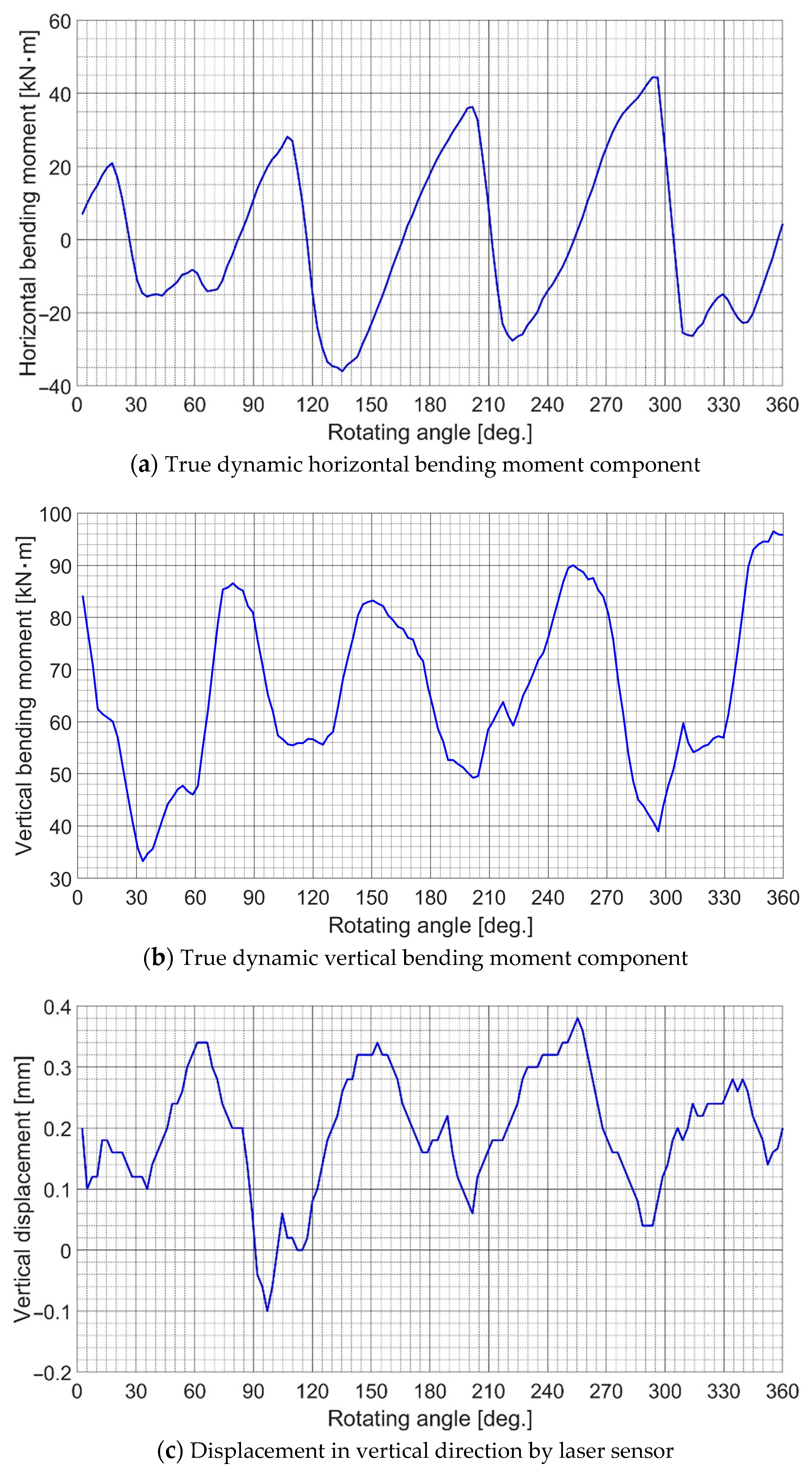
  • In case the second bridge, S2, is not available, the true dynamic bending moment can be measured by using the actual bending stress combined with the phase lag stress of the only one bridge of strain gauge at an angle of 90°. The waveform of the established true bending moment was similar to the waveform of the measured displacement. The mean values (average values) of the established true dynamic bending moment were the same as the values of the nominal bending moment obtained by the conventional method. Both waveforms and amplitudes were validated. These confirmed the accuracy of the suggested method.
  • The rapid change in the ship’s heading caused a sudden change in the wake-field, which temporarily applied excessive load to the propeller blades and then transmitted to the shaft and bearings. The bending moment of the propeller shaft had moved upward clockwise at the beginning, then returned in the same trajectory at the end of the starboard turn. The propeller operated as a seesaw, which confirmed the increased load on the ASTB. The phenomenon occurred in the opposite direction during the port turn.
  • The moment orbit when the rudder angle was 12 degrees is larger than the other stages with respect to the greater propeller force fluctuation. This occurred more clearly in the case of the starboard turn, resulting in a non-uniform oil film on the bearings. This instability can be referred to as an oil whirl. When the oil whirl becomes intense, it becomes an oil whip, which possibly leads to bearing wear and premature failure. The fluctuation behavior was not significant, but early detection of instability is essential for the safe operation of bearings.
  • In further work, the displacement sensors should be installed on both vertical and horizontal directions to fully cross-verify the behavior of the bending moment. Additionally, the establishing method presented in this research can be applied in the case of a four-blade propeller. In other cases, it is recommended to install two bridges of strain gauge for each shaft cross-section in order to directly establish the true dynamic bending moment.

Author Contributions

Q.D.V. and J.-u.L. have contributed equally to this work. Conceptualization, Q.D.V., J.-w.L. and J.-u.L.; methodology, J.-u.L. and Q.D.V.; software, Q.D.V., Y.K. and K.S.; validation, Q.D.V., J.-w.L., M.-h.S. and J.-u.L.; formal analysis, Q.D.V. and J.-u.L.; investigation, J.-w.L., Y.K., K.S. and Q.D.V.; resources, Q.D.V. and J.-u.L.; data curation, Q.D.V., K.S., J.H.J. and J.-u.L.; writing—original draft preparation, J.-w.L., Q.D.V., H.C. and J.-u.L.; writing—review and editing, M.-h.S., W.-J.L., H.C. and J.-u.L.; visualization, Q.D.V., Y.K. and J.-w.L.; supervision, M.-h.S., W.-J.L. and J.-u.L.; project administration, J.H.J., H.C. and J.-u.L.; funding acquisition, J.-u.L. All authors have read and agreed to the published version of the manuscript.

Funding

This research was supported by the ‘Development of Autonomous Ship Technology (20200615)’ funded by the Ministry of Oceans and Fisheries (MOF, Korea).

Institutional Review Board Statement

Not applicable.

Informed Consent Statement

Not applicable.

Data Availability Statement

Not applicable.

Acknowledgments

This work was supported by the National Research Foundation of Korea (NRF) grant funded by the Korea government (MSIT) (No. NRF-2021R1F1A1047115). This research was supported by the BB21plus funded by Busan Metropolitan City and Busan Institute for Talent & Lifelong Education (BIT).

Conflicts of Interest

The authors declare no conflict of interest.

References

  1. Lehr, W.; Parker, E. Considerations in the design of marine propulsion shaft systems. Soc. Nav. Archit. Mar. Eng. 1961, 67, 555. [Google Scholar]
  2. Mann, G. Design of propulsion shaft systems using fair curve alignment theory. Nav. Eng. J. 1964, 76, 851–862. [Google Scholar]
  3. Mann, G. Analysis of shafting problems using fair curve alignment theory. Nav. Eng. J. 1965, 77, 117–133. [Google Scholar] [CrossRef]
  4. Mann, G. Shipyard alignment of propulsion shafting using fair curve alignment theory. Nav. Eng. J. 1965, 77, 651–659. [Google Scholar] [CrossRef]
  5. Larsen, O. Some considerations of marine shafting design. Ind. Lubr. Tribol. 1981, 33, 204–237. [Google Scholar] [CrossRef]
  6. Kuroiwa, R.; Oshima, A.; Nishioka, T.; Tateishi, T.; Ohyama, K.; Ishijima, T. Reliability Improvement of Stern Tube Bearing Considering Propeller Shaft Forces during Ship Turning; Technical Review; Mitshbishi Heavy Industries, Ltd.: Tokyo, Japan, 2007; Volume 44, pp. 1–3. [Google Scholar]
  7. Vartdal, B.J.; Gjestland, T.; Arvidsen, T.I. Lateral propeller forces and their effects on shaft bearings. In Proceedings of the First International Symposium on Marine Propulsors, Trondheim, Norway, 22–24 June 2009; pp. 475–481. [Google Scholar]
  8. Dubbioso, G.; Muscari, R.; Ortolani, F.; Di Mascio, A. Analysis of propeller bearing loads by CFD. Part I: Straight ahead and steady turning maneuvers. Ocean Eng. 2017, 130, 241–259. [Google Scholar] [CrossRef]
  9. Muscari, R.; Dubbioso, G.; Ortolani, F.; Di Mascio, A. Analysis of propeller bearing loads by CFD. Part II: Transient maneuvers. Ocean Eng. 2017, 146, 217–233. [Google Scholar] [CrossRef]
  10. Lee, J.-U. Application of strain gauge method for investigating influence of ship shaft movement by hydrodynamic propeller forces on shaft alignment. Measurement 2018, 121, 261–275. [Google Scholar] [CrossRef]
  11. Choi, S.-P.; Lee, J.-U.; Park, J.-B. Application of Deep Reinforcement Learning to Predict Shaft Deformation Considering Hull Deformation of Medium-Sized Oil/Chemical Tanker. J. Mar. Sci. Eng. 2021, 9, 767. [Google Scholar] [CrossRef]
  12. Song, G.; Park, H.; Lee, T. The Effect of Rudder Existence on Propeller Eccentric Force. J. Mar. Sci. Eng. 2019, 7, 455. [Google Scholar] [CrossRef]
  13. Class, N.K. Guidelines on Shafting Alignment; Class NK: Tokyo, Japan, 2006. [Google Scholar]
  14. MAN Energy Solutions. Final Alignment of Engine on Board; MAN Energy Solutions: Augsburg, Germany, 2014; p. 5. [Google Scholar]
  15. MAN Energy Solutions. Bearing Load Measurement by Jacking Up; MAN Energy Solutions: Augsburg, Germany, 2012; p. 23. [Google Scholar]
  16. MAN B&W G-Engines. Available online: https://www.mandieselturbo.com/docs/default-source/shopwaredocuments/man-b-w-g-engines-green-ultra-long-stroke-engines15fbf9a55cda459c8d405548eea8e7e1.pdf?sfvrsn=3 (accessed on 20 July 2022).
  17. Ultra Long Stroke Engine. Available online: https://www.wartsila.com/encyclopedia/term/ultra-long-stroke-engine (accessed on 20 July 2022).
  18. Wake-Field. Available online: https://www.wartsila.com/encyclopedia/term/wake-field (accessed on 20 July 2022).
  19. Mikkelsen, H.; Shao, Y.; Walther, J.H. Numerical study of nominal wake fields of a container ship in oblique regular waves. Appl. Ocean Res. 2022, 119, 102968. [Google Scholar] [CrossRef]
  20. Sprenger, F.; Maron, A.; Delefortrie, G.; Cura-Hochbaum, A.; Papanikolaou, A. Experimental studies on seakeeping and manoeuvrability in adverse weather conditions. J. Ship Res. 2016, 61, 131–152. [Google Scholar] [CrossRef] [Green Version]
  21. Valanto, P.; Hong, Y. Experimental investigation on ship wave added resistance in regular head, oblique, beam, and following waves. In Proceedings of the Twenty-fifth International Ocean and Polar Engineering Conference, Kona, HI, USA, 21–26 June 2015. [Google Scholar]
  22. Wu, T.C.; Deng, R.; Luo, W.Z.; Sun, P.N.; Dai, S.S.; Li, Y.L. 3D-3C wake field measurement, reconstruction and spatial distribution of a Panamax Bulk using towed underwater 2D-3C SPIV. Appl. Ocean Res. 2020, 105, 102437. [Google Scholar] [CrossRef]
  23. Sun, S.; Chang, X.; Wang, W.; Guo, C.; Zhang, H. Numerical simulation of wake field and propulsion performance in a four-screw ship. Ocean Eng. 2019, 186, 106092. [Google Scholar] [CrossRef]
  24. Sadat-Hosseini, H.; Toxopeus, S.; Kim, D.H.; Castiglione, T.; Sanada, Y.; Stocker, M.; Simonsen, C.; Otzen, J.F.; Toda, Y.; Stern, F. Experiments and computations for KCS added resistance for variable heading. In Proceedings of the SNAME Maritime Convention and 5th World Maritime Technology Conference, Providence, RI, USA, 3–7 November 2015. [Google Scholar]
  25. Lee, J.-W.; Vuong, Q.D.; Jeong, B.; Lee, J.-U. Changes in Propeller Shaft Behavior by Fluctuating Propeller Forces during Ship Turning. Appl. Sci. 2022, 12, 5041. [Google Scholar] [CrossRef]
  26. Grant, R.B. Shaft Alignment Methods with Strain Gages and Load Cells. Mar. Technol. 1980, 17, 8–15. [Google Scholar] [CrossRef]
  27. Forrest, A.W.; Labasky, R.F. Shaft alignment using strain gages. Mar. Technol. 1981, 18, 276–284. [Google Scholar] [CrossRef]
  28. Cdr Amit Batra, L.; Shankar, K.; Swarnamani, S. Propulsion shaft alignment measurements on warships afloat and alignment solution using multi-objective optimisation. J. Mar. Eng. Technol. 2007, 6, 39–49. [Google Scholar] [CrossRef]
  29. Zhang, S.; Yang, J.; Li, Y.; Li, J. Identification of bearing load by three section strain gauge method: Theoretical and experimental research. Measurement 2013, 46, 3968–3975. [Google Scholar] [CrossRef]
  30. Avgouleas, K.; Sarris, E.; Gougoulidis, G. Practical Aspects of Propulsion Shaft Alignment. In Proceedings of the SNAME 7th International Symposium on Ship Operations, Management and Economics, Virtual, 6–7 April 2021. [Google Scholar]
  31. Batrak, Y.; Batrak, R.; Berin, D.; Mikhno, A. Propulsion shafting whirling vibration: Case studies and perspective. In Proceedings of the SNAME 14th Propeller and Shafting Symposium, Norfolk, VA, USA, 15–16 September 2015. [Google Scholar]
  32. Zhang, W.; Yang, J.; Li, C.; Dai, R.; Yang, A. Theoretical and experimental research on turbo-generator shaft alignment using strain gauge method. J. Vib. Control 2017, 23, 1183–1192. [Google Scholar] [CrossRef]
  33. Ho, W.H.; Tsai, J.T.; Chou, J.H.; Yue, J.B. Intelligent hybrid Taguchi-genetic algorithm for multi-criteria optimization of shaft alignment in marine vessels. IEEE Access 2016, 4, 2304–2313. [Google Scholar] [CrossRef]
  34. Iriarte, X.; Aginaga, J.; Gainza, G.; Ros, J.; Bacaicoa, J. Optimal strain-gauge placement for mechanical load estimation in circular cross-section shafts. Measurement 2021, 174, 108938. [Google Scholar] [CrossRef]
  35. ISO 20283-4:2012; Mechanical Vibration—Measurement of Vibration on Ships—Part 4: Measurement and Evaluation of Vibration of the Ship Propulsion Machinery. International Organization for Standardization: Geneva, Switzerland, 2012.
  36. Measuring Strain with Strain Gages—NI. Available online: https://www.ni.com/en-us/innovations/white-papers/07/measuring-strain-with-strain-gages.html (accessed on 20 July 2022).
  37. Hoffmann, K. An Introduction to Measurements Using Strain Gages; Hottinger Baldwin: Darmstadt, Germany, 1989. [Google Scholar]
  38. Wheatstone Bridge. Working, Examples, Applications. Available online: https://www.electronicshub.org/wheatstone-bridge/ (accessed on 20 July 2022).
  39. Lee, T.G.; Song, G.S.; Kim, J.N.; Lee, J.S.; Park, H.G. Effect of propeller eccentric forces on the bearing loads of the complicated shafting system for large container ships. In Proceedings of the Fifth International Symposium on Marine Propulsors, Espoo, Finland, 12–15 June 2017. [Google Scholar]
  40. Soares, C. (Ed.) Chapter 3—Gas Turbine Configurations and Heat Cycles. In Gas Turbines, 2nd ed.; Butterworth-Heinemann: Oxford, UK, 2015; pp. 93–171. [Google Scholar]
  41. Boyce, M.P. (Ed.) 5—Rotor Dynamics. In Gas Turbine Engineering Handbook, 4th ed.; Butterworth-Heinemann: Oxford, UK, 2012; pp. 215–250. [Google Scholar]
  42. Mobley, R.K. (Ed.) 60—Bearings. In Plant Engineer’s Handbook; Butterworth-Heinemann: Oxford, UK, 2001; pp. 1081–1100. [Google Scholar]
  43. Mishra, P.C.; Rahnejat, H. 20—Tribology of big-end bearings. In Tribology and Dynamics of Engine and Powertrain; Woodhead Publishing: Cambridge, UK, 2010; pp. 635–659. [Google Scholar]
Figure 1. The flowchart of research approach.
Applsci 12 09235 g001
Figure 2. The Wheatstone half-bridge strain gauge configuration for bending moment measurement.
Applsci 12 09235 g002
Figure 4. True dynamic bending moment measurement using two bridges of strain gauge.
Applsci 12 09235 g004
Figure 5. Equipment installation in engine room.
Applsci 12 09235 g005
Figure 6. Sea-trial procedure of the case ship. (1) Rudder angle 0 degrees; (2) Rudder angle changes from 0 to 12 degrees (port or starboard); (3): Rudder angle 12 degrees; (4) Rudder angle 0 degrees.
Applsci 12 09235 g006
Figure 7. Vibration behavior during a full revolution during NCR straight going.
Applsci 12 09235 g007
Figure 8. True dynamic bending moment in the horizontal direction during rapid port turn.
Applsci 12 09235 g008
Figure 9. True dynamic bending moment in the vertical direction during rapid port turn.
Applsci 12 09235 g009
Figure 10. Displacement in vertical direction during rapid port turn.
Applsci 12 09235 g010
Figure 11. Trajectory plot of bending moment during rapid port turn. (a) Nominal bending moment; (b) True dynamic bending moment (orbit plot).
Applsci 12 09235 g011
Figure 12. Trajectory plot of bending moment during rapid starboard turn. (a) Nominal bending moment; (b) True dynamic bending moment (orbit plot).
Applsci 12 09235 g012
Table 1. Specifications of ship and propulsion system.
Ship Propeller
TypeOil/chemical tankerManufacturerHMD
Deadweight50,000 DWTTypeFixed pitch propeller
Dimension174.0 m × 32.2 m × 19.1 mNumber of blades4
Diameter6600 mm
Main engineMaterialNi-Al-Bronze
ManufacturerMAN B&WMass18,200 kg
Type6G50ME-BCap and nut mass1538 kg
MCR7700 kW × 93.4 rpm
NCR5344 kW × 82.7 rpmPropeller shaft
MaterialForged steel
Flywheel Diameter500 mm
Mass 11,207 kgTensile strength600 N/mm2
Publisher’s Note: MDPI stays neutral with regard to jurisdictional claims in published maps and institutional affiliations.

