


Numerical Simulation Research on Mechanical Optimization of a Novel Fastener Type Ballastless Track (NFTBT) for Tram
Abstract
:1. Introduction
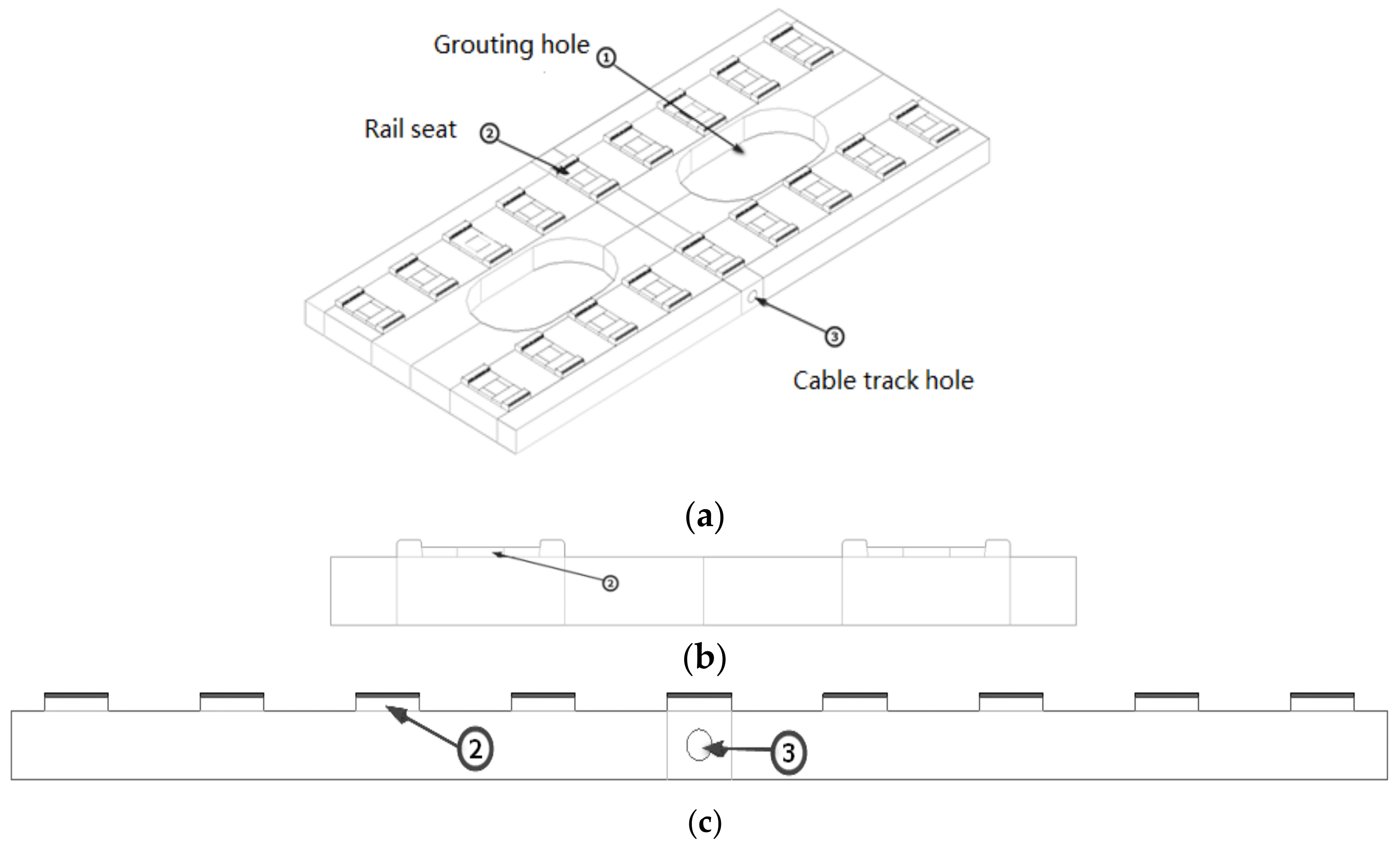
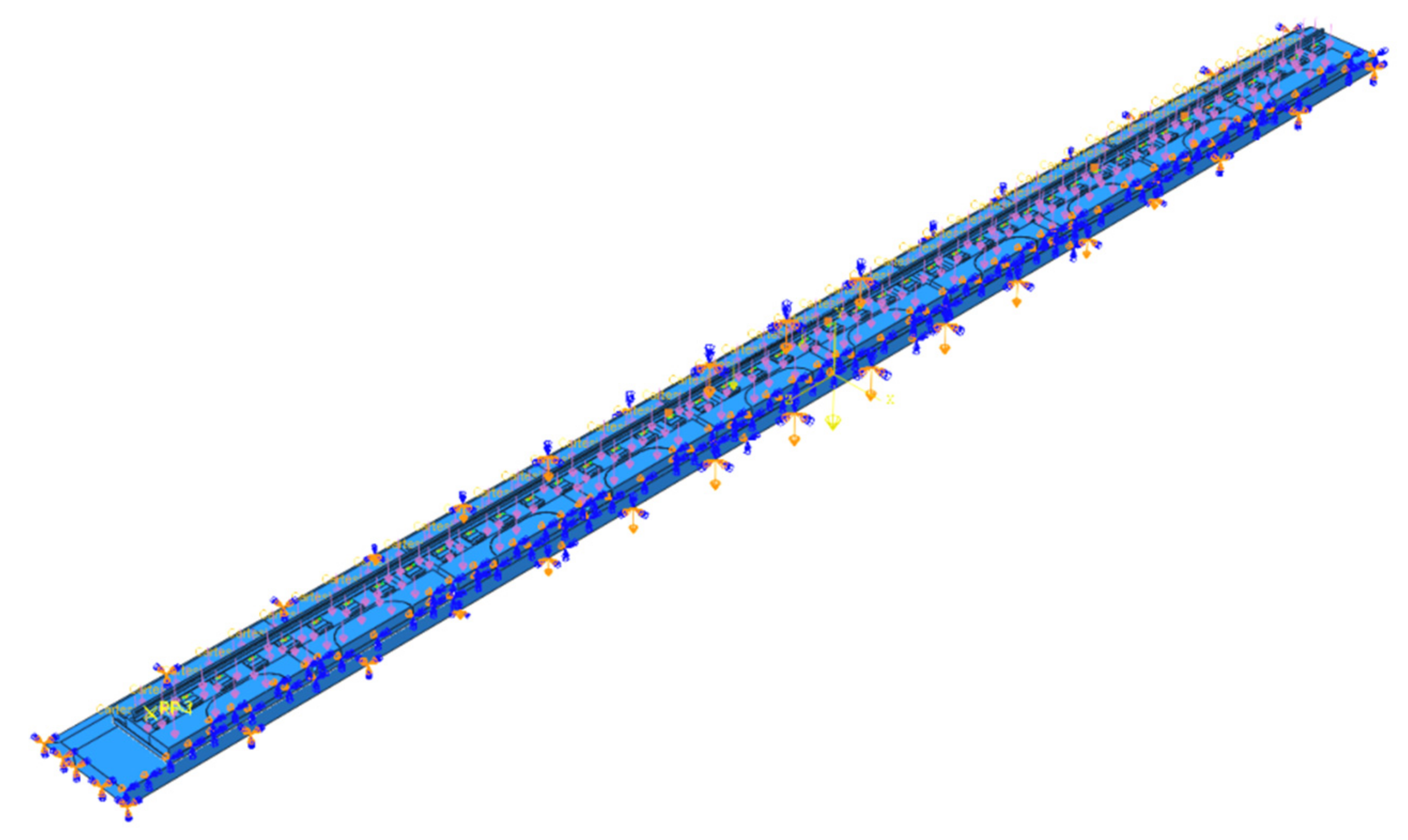
2. NFTBT Finite Element Model Establishment
2.1. Finite Element Model Parameters
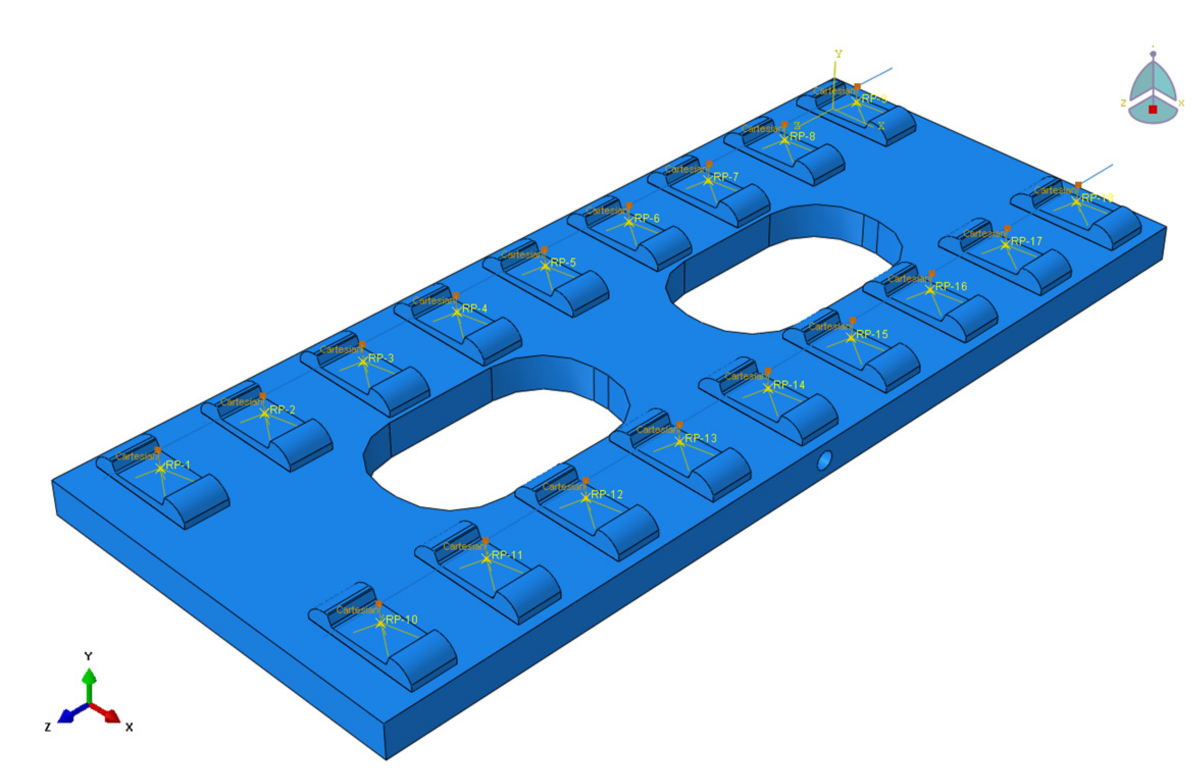
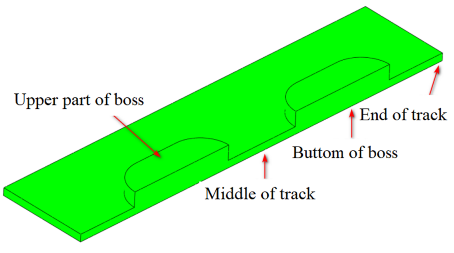
2.2. Displacement and Stress Measuring Point Layout
2.3. Working Condition Setting
- (1)
- Length of the track slab
- (2)
- Width of the track slab
- (3)
- Thickness of the track slab
- (4)
- Distance between the centers of the adjacent grouting holes
- (5)
- Distance between the adjacent fasteners
3. Influence of NFTBT Structure’s Size Parameters
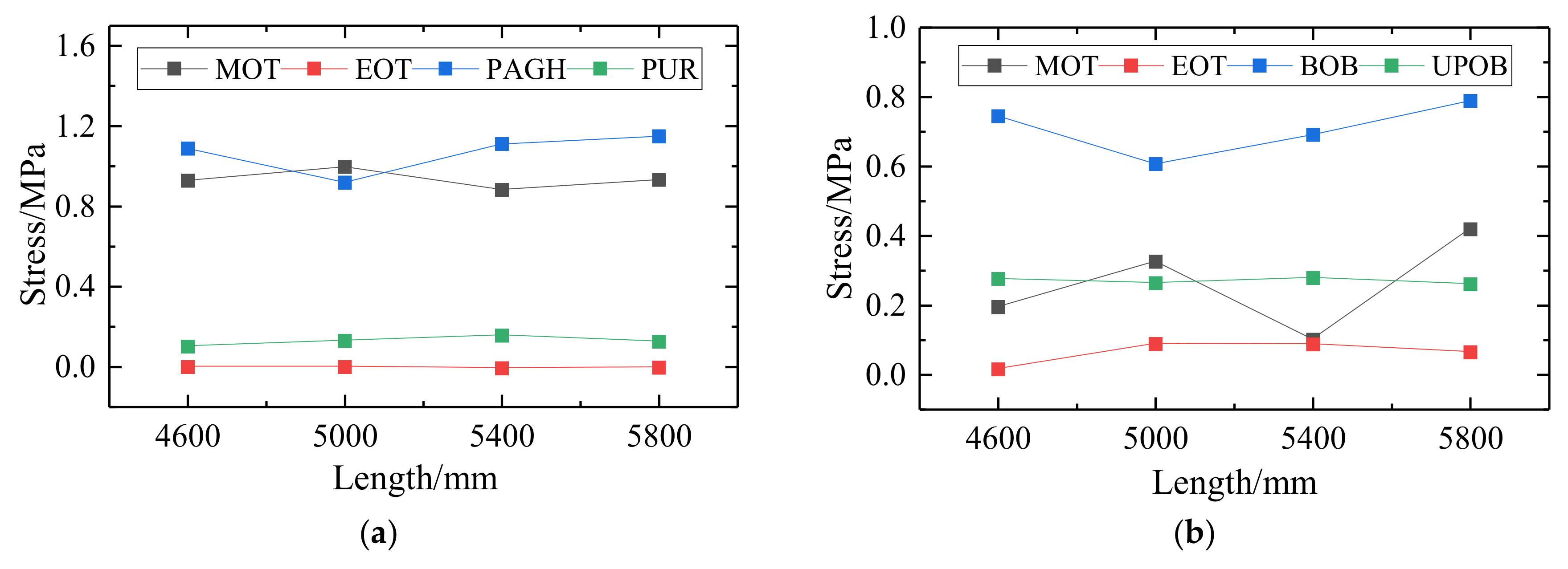
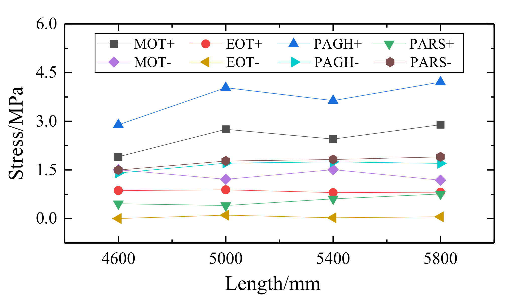
3.1. Influence of Length of Track Slab
- (1)
- As the length of the NFTBT increases, the stress at the center of the track slab and the adjustment layer first increases and then decreases, reaching the minimum point at 5400 mm, while the stress at the end of the track slab does not change much. With each slab under long-term conditions, the track slab stress changes little and shows a downward trend, but the stress changes in the adjustment layer are larger and increase further.
- (2)
- With the increase in the length of the NFTBT, the stress at the grouting hole fluctuates greatly, and the stress value at the grouting hole of the track slab and the adjustment layer is the smallest at 5000 mm. In order to achieve the NFTBT’s optimal construction, the area of the grouting hole of the track slab must inevitably increase, and the stress state at the boss of the adjustment layer will change from compression to tension. Therefore, the length of the track slab needs to be restricted.
- (3)
- The stress difference in key positions of the NFTBT’s structure under different slab length conditions is small (0.25 Mpa), and the stress in the track slab has an opposite trend to the stress of the grouting hole. The stress amplitude of the adjustment layer is smaller than that of the track slab. Since the grouting hole is often a weak link in the construction process, considering the impact of later maintenance, it is recommended that the length of the NFTBT be 5000 mm.
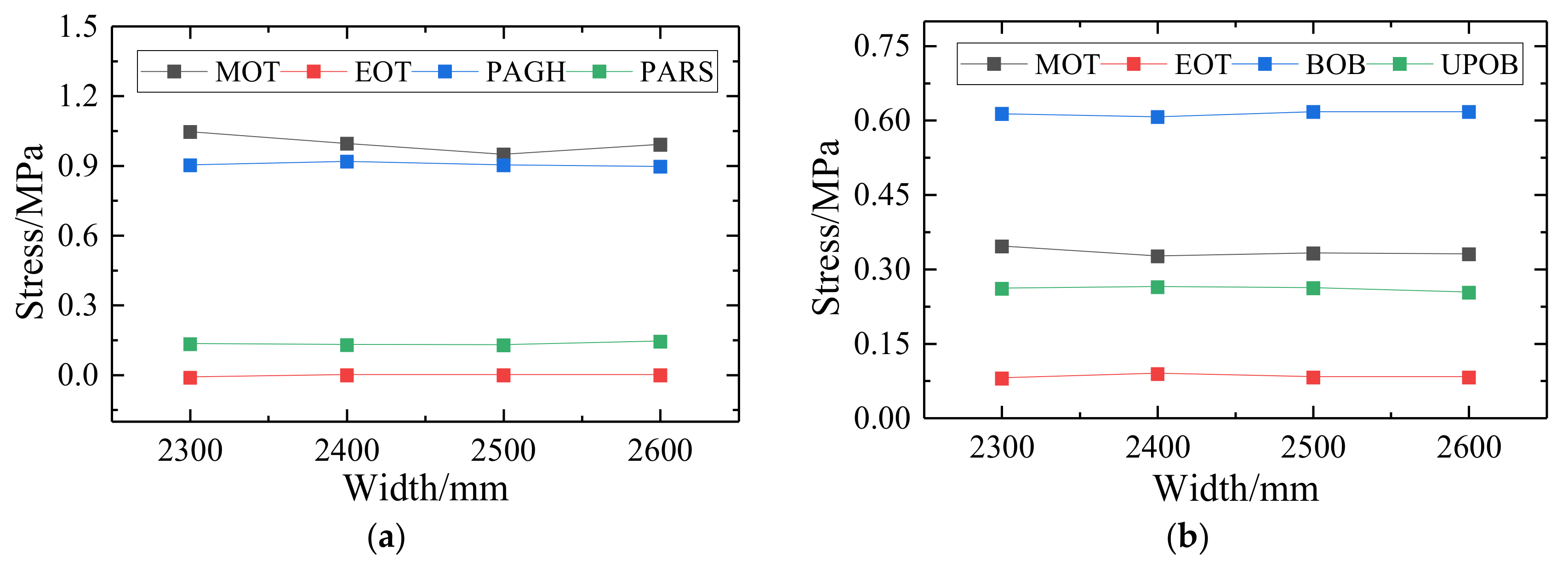
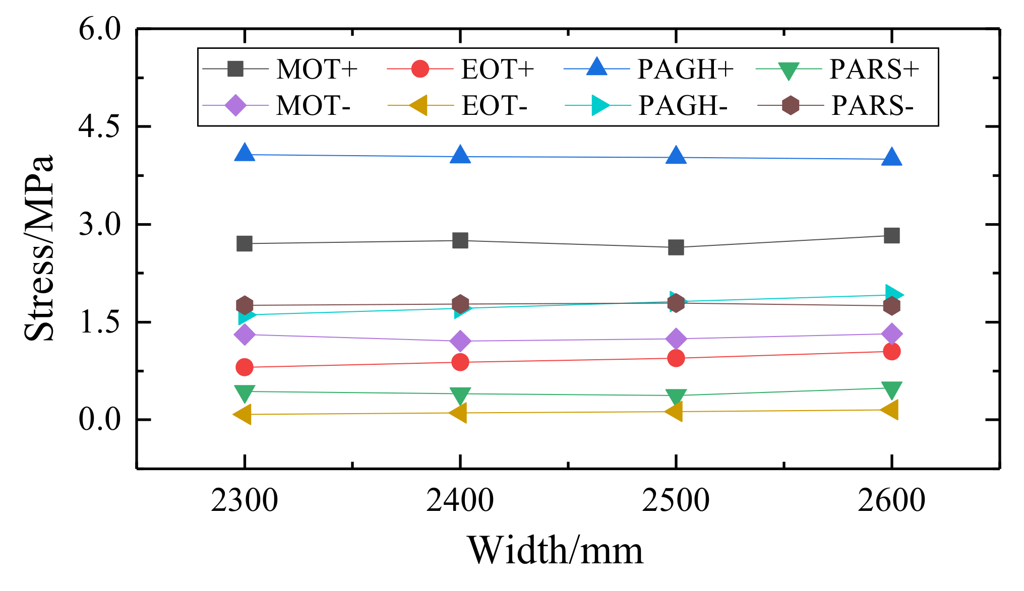
3.2. Influence of Width of Track Slab
- (1)
- In the case of the width of the track slab, the stress changes at each measuring point are not large. Since the grouting hole and the stress in the track slab are the largest, the stress and displacement of the grouting hole and the center of the track are the control factors for the optimal design of the NFTBT at this stage.
- (2)
- As the width of the track slab increases, the stress in the track slab varies the most, showing a trend of first decreasing and then increasing, while the stress at the grouting hole first increases and then decreases very steadily. However, the stress variation of the whole NFTBT’s structure is not large (<0.097 MPa)
- (3)
- The stress difference in key positions of the NFTBT’s structure under different width conditions is small, and the width of the track slab also affects the overall area and weight of the structure and the occupied land. Considering the stress and deformation of the track structure, uneven settlement, and the conditions under the combined effect of the tram load, in order to facilitate construction and maintenance, the width of the NFTBT should not be too long, so 2400 mm and 2500 mm are recommended as the width for site laying.
3.3. Influence of Thickness of Track Slab
- (1)
- As the thickness of the track slab increases, the self-weight of the NFTBT’s structure will gradually increase, which will adversely affect the maximum stress of the track slab. At this time, the stress of the grouting hole increases rapidly, and the stress in the track slab first decreases and then increases. The stress of the boss in the adjustment layer shows an increasing trend, while the stress changes in other positions are smaller.
- (2)
- The stress at the grouting hole and the stress in the track slab are the key control factors for the optimal design of the track structure at this stage. As the slab thickness increases, the local stress at the grouting hole increases and is relatively rapid; the stress in the slab first rises and then drops. There is a minimum turning point in the three working conditions, and both turning points appear near the thickness of 200 mm. At this time, the stress of the adjustment layer is basically unchanged.
- (3)
- Since the thickness of the track slab has a greater impact on construction and economy, it is not the case that the thicker the track slab, the better the overall performance. Synthesizing the law of stress change at each key position, considering the maximum stress at different positions of the track slab, when the thickness of 200 mm is adopted, the stress of the track structure is more favorable than other working conditions.

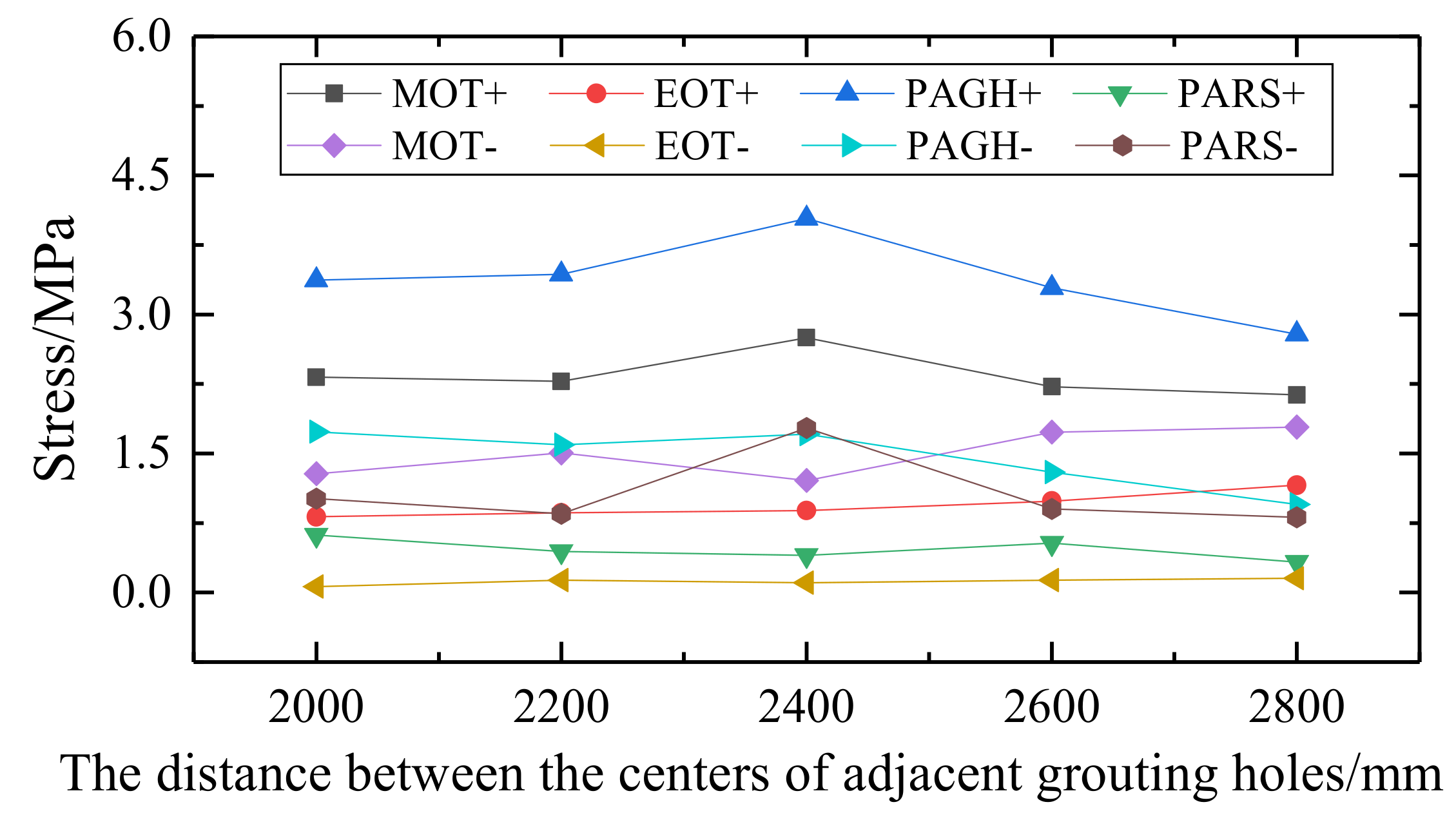
3.4. Influence of Distance between the Centers of Adjacent Grouting Holes
- (1)
- The stress difference of the NFTBT’s structure under the different distance between the centers of the adjacent grouting holes conditions is small (<0.2 MPa); the stress value of the NFTBT slab and the grouting hole is larger, and the stress change amplitude of other parts including the rail platform is small. It is evident that the distance between the grouting holes has little effect on the overall force of the track structure.
- (2)
- The stress amplitude of each measuring point at the adjustment layer is smaller than the track slab, and the overall change amplitude is much smaller than the strength value of the concrete. Among them, the stress amplitude at the bottom of the boss is larger, and there is a minimum value when the center distance of the adjacent grouting hole is 2400 mm.
- (3)
- The change in the center distance between the grouting holes has little effect on the stress of the track structure. However, a larger distance between the centers of the adjacent grouting holes can reduce the number of grouting holes in the track slab. For a comparative analysis, it is recommended to set the distance between the centers of the adjacent grouting holes to 2200 mm according to the length of the track slab.

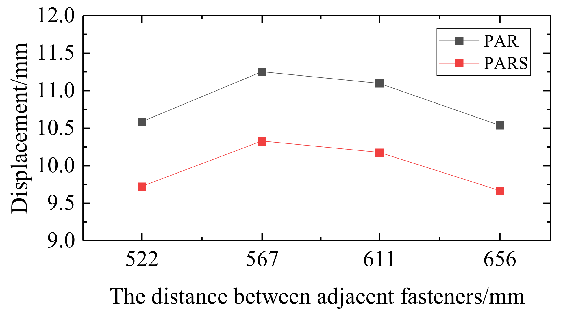
3.5. Influence of Distance between Adjacent Fasteners
- (1)
- As the distance between the adjacent fasteners increases, the displacement of the NFTBT rail and rail platform first increases and then decreases, indicating that when the distance between the adjacent fasteners changes within a certain range, the rail is more affected by the uneven settlement of the subgrade, which is due to the larger track irregularity.
- (2)
- As the distance between the adjacent fasteners increases, the rail stress presents an upward trend: the greater the distance between the adjacent fasteners, the more intense the rising trend of rail stress. The stress at the bottom of the track slab first decreases and then increases, indicating that the distance between the adjacent fasteners is at a certain level. When the range is changed, the peak stress at the bottom of the NFTBT can be reduced.
- (3)
- Since the fasteners should have sufficient strength, buckle pressure, proper gauge and level adjustment, good elasticity, and insulation, they should also be standardized as much as possible, simple in structure, and easy to lay and repair. Therefore, the impact of the distance between the adjacent fasteners is related to the overall stiffness of the NFTBT and the ease of construction. Based on the comparative analysis of the displacement and stress changes of the track structure, the recommended distance between the adjacent fasteners is 567 mm.

4. Conclusions
- (1)
- When uneven settlement occurs in the subgrade part of the track structure, under the combined action of the tram load and the uneven settlement, as the size (length, width, and thickness) of the track slab increases, the displacement of the middle part of the NFTBT is similar, and the track operates under various working conditions. The difference in the degree of slab deformation is small. It is evident that the size of the track slab has little effect on displacement and stress. The size of the track slab affects the overall area and weight of the structure and its land occupation, as evidenced by the stress and deformation of the track structure. Under the combined action of uniform settlement and tram load to facilitate construction and maintenance, the size of the NFTBT should not be too large.
- (2)
- The stress difference of the NFTBT’s structure under the different distances between the centers of the adjacent grouting holes conditions is small, the stress values of the NFTBT slab and grouting hole are larger, and the stress change amplitude of other parts, including the rail platform, is small, showing the distance between the centers of the adjacent grouting holes. The influence on the overall force of the track structure is small. Although a larger distance between the centers of the adjacent grouting holes can reduce the number of grouting holes in the track slab, the center distance of the grouting holes will affect the pouring properties of the adjustment layer, so the spacing should not be too large.
- (3)
- The influence of the distance between the adjacent fasteners is related to the overall stiffness of NFTBT and the convenience of construction. The rail is greatly affected by the uneven settlement of the subgrade, and the track irregularity also increases. As the distance between the adjacent fasteners increases, the rail stress shows an upward trend. The greater the distance between the adjacent fasteners, the more intense the increase in the rail stress; the stress at the bottom of the track slab first decreases and then increases, indicating that the distance between the adjacent fasteners changes within a certain range. At this time, the peak stress at the bottom of the NFTBT can be reduced.
- (4)
- Based on the comparative analysis results of the above working conditions, it is recommended that the NFTBT’s structure adopts a unit-slab design, which is composed of rails, fasteners, prefabricated track slabs, adjustment layers, support layers, and other parts. The track slab is a unit-slab structure prefabricated by C60 concrete in the factory. The track slab should have a width of 2400 mm, a thickness of 200 mm, a length of 5000 mm, and a 100 mm expansion joint between the slabs; each track slab should be equipped with two” Semicircle + rectangle + semicircle” grouting holes, the rectangle size should be 800 × 400 mm, the circle diameter should be 800 mm, the center distance should be 2200 mm, and the distance between the adjacent fasteners should be 567 mm.
- (5)
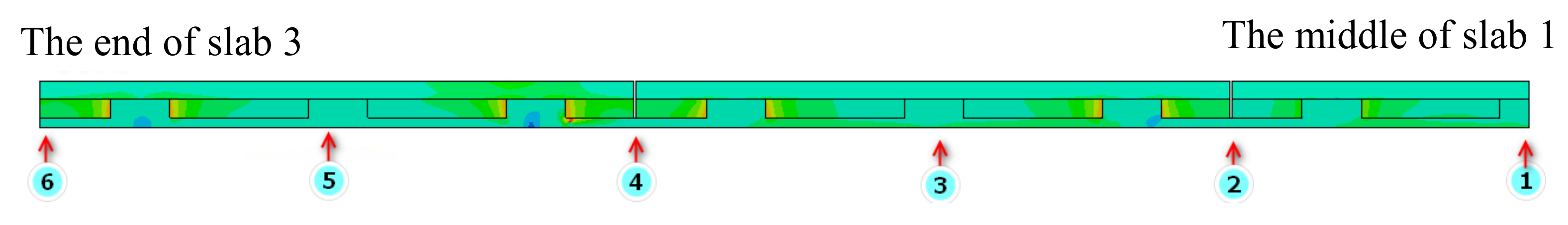
- Under the influence of temperature load, the stress of the track slab and adjustment layer increases gradually with the increase in the slab length, and the stress trend in the slab under negative temperature is the opposite; with the increase of the width of the track slab, the stress state of the track slab is more unfavorable, especially at the slab end, which may cause the separation of the contact surface between the self-compacting concrete and the adjustment layer; with the increase of the slab thickness, the stress of the grouting holes first increases and then decreases, whereas under a negative temperature, the stress in the slab increases with the increase of slab thickness; when the track slab bears the temperature load, the stress at the grouting hole of the track slab is the largest under the positive temperature gradient, so the stress at the grouting hole is the control index of the optimal design. Therefore, reasonable parameter settings should be combined with local temperature changes during design.
- (6)
- The NFTBT does not require the implementation of cable passages at intervals, which facilitates the passage and fixation of cables in the tram’s operation section, and can reduce the difficulty of adjusting the geometry of the track structure, thus accelerating the construction progress. Therefore, the research regarding the NFTBT is very important for the modern innovation of tram track structures and has a guiding significance. At the same time, it can also provide theoretical references for related tram track structure research.
Author Contributions
Funding
Institutional Review Board Statement
Informed Consent Statement
Data Availability Statement
Conflicts of Interest
References
- Shan, Y.; Zhou, X.; Cheng, G.; Jiang, Z.; Zhou, S. In-situ test on impact loads of a five-module 100% low-floor tram and the prediction of damage characteristics of a pile-plank-supported tram track. Constr. Build. Mater. 2021, 277, 122320. [Google Scholar] [CrossRef]
- Falamarzi, A.; Moridpour, S.; Nazem, M. A time-based track quality index. Melbourne tram case study. Int. J. Rail Transp. 2021, 9, 23–38. [Google Scholar] [CrossRef]
- Andrzej, W.; Cezary, S.; Wladyslaw, K.; Karwowski, K.; Skibicki, J.; Szmagliński, J.; Chrostowski, P.; Dabrowski, P.; Specht, M.; Zienkiewicz, M.; et al. Evaluation of the Possibility of Identifying a Complex Polygonal Tram Track Layout Using Multiple Satellite Measurements. Sensors 2020, 20, 4408. [Google Scholar]
- Wenjing, S.; David, T.; Martin, T.; Zeng, Z. Modelling of vibration and noise behaviour of embedded tram tracks using a wavenumber domain method. J. Sound Vib. 2020, 481, 115446. [Google Scholar]
- Shan, Y.; Wang, B.; Zhang, J.; Zhou, S. The influence of dynamic loading and thermal conditions on tram track slab damage resulting from subgrade differential settlement. Eng. Fail. Anal. 2021, 128, 105610. [Google Scholar] [CrossRef]
- Leune, P.; Steen, E.; De Paepe, P.; Lyphout, C. An overview of tram tracks related cycling injuries in Ghent, Belgium. Traffic Inj. Prev. 2021, 22, 261–265. [Google Scholar] [CrossRef]
- Kurbatova, A.; Majercak, J.; Majercak, P.; Kurbatova, E. The operation of trams on a tramway track in Kosice, and their technical issues. IOP Conference Series. Mater. Sci. Eng. 2020, 918, 012152. [Google Scholar]
- Ma, X.; Fang, Z.; Liang, K.; Hu, J.; Wu, Q.; Huang, X.; Xie, Y. Design and Validation of an auxiliary automatic running system for tram track cleaning vehicles based on ROS. Journal of Physics. Conf. Ser. 2021, 1883, 0120127. [Google Scholar] [CrossRef]
- Shan, Y.; Zhou, X.; Zhou, S. One-dimensional semi-analytical model on longitudinal thermal loads of a tram track pile-plank structure buried beneath the pavement. Arch. Civ. Mech. Eng. 2021, 21, 36. [Google Scholar] [CrossRef]
- Shim, D.W.; Kim, S.; Hwang, Y.; Lee, Y.; Lee, J.W.; Han, S.H. Detection of the Tram Track Lesion in the Ankle Joint. Comparing 3.0-Tesla Magnetic Resonance Imaging and Arthroscopy. Arthroscopy. J. Arthrosc. Relat. Surg. 2018, 34, 866–871. [Google Scholar] [CrossRef]
- Huang, D.; Feng, Q.-S.; Luo, X.-W.; Luo, K.; Liu, Q.-J.; Sun, K. Site Investigation and Analysis of the Tramway Diseases. J. East China Jiaotong Univ. 2019, 36, 12–17. (In Chinese) [Google Scholar]
- Feng, Q.-S.; Sun, K.; Luo, X.-W.; Liu, Q.-Z. Optimization Analysis of Short Sleeper Embedded Track Subgrade of Modern Tram. J. Railw. Eng. Soc. 2018, 35, 23–28. (In Chinese) [Google Scholar]
- Feng, Q.-S.; Sun, K.; Luo, X.-W.; Liu, Q.-Z. Longitudinal Force Analysis of Tram Embedded Track on Simply Supported Bridge. J. Railw. Eng. Soc. 2017, 34, 27–32. (In Chinese) [Google Scholar]
- Di, Y.; Li, D.; Dong, C.; Xu, D.; Yan, H.; Cong, Y.; Gao, S.; Li, Z.; Wang, W.; Yin, H.; et al. A Novel Type of Fastener Type Prefabricated Track Slab Structure for Tram. Chinese Patent CN212771764U, 23 March 2021. (In Chinese). [Google Scholar]
- Sun, K.; Feng, Q.-S.; Wang, W.; Chen, Y.-M. Multi-objective optimization of long sleeper embedded track composite foundation for tram. J. Huazhong Univ. Sci. Technol. (Nat. Sci. Ed.) 2019, 47, 55–60. (In Chinese) [Google Scholar]
- Feng, Q.-S.; Sun, K.; Lei, X.-Y.; Luo, K.; Liu, Q.-J. Study on dynamic stress distribution law of embedded track subgrade of tram. J. Railw. Sci. Eng. 2019, 16, 885–891. (In Chinese) [Google Scholar]
- Gao, L.; Peng, H. The Dynamic Effect of the Modes of Replacing Sleepers on Track Structure in High-speed Railway. In Proceedings of the International Symposium on Traffic Induced Vibrations and Controls (TIVC2001), Beijing, China, 6–7 November 2001. [Google Scholar]
- Gao, L.; Peng, H. Setting Modes of Sleeper on HSR Bridge-roadbed Transition Sections for Ballast Track. In Proceedings of the International Symposium on Traffic Induced Vibrations and Controls (TIVC2001), Beijing, China, 6–7 November 2001. [Google Scholar]
- Chen, P. Influence of Groove Rail and General Rail on the Dynamic Characteristics of Light Rail Vehicles with Independent Wheel Set. Urban Mass Transit 2012, 15, 65–68. (In Chinese) [Google Scholar]
- Zhao, W.; Wang, C.; Zhang, J.; Du, L.-M. Research on Matching of Railway Wheel and Rail Profiles. J. China Railw. Soc. 2011, 33, 34–37. (In Chinese) [Google Scholar]
- Gao, J. Track Structure of Translohr Tram. Urban Mass Transit 2012, 4, 98–102. (In Chinese) [Google Scholar]
- Li, J.; Xu, Y.-J.; Ren, J.-J.; Liu, X.-Y. Study on Parameters of Modern Tram Single slab Track Structure. Railw. Stand. Des. 2015, 59, 24–28. (In Chinese) [Google Scholar]
- Wang, S. Mechanical Response and Design Parameters of Tram Subgrade with Monolithic Track-Bed; Tongji University: Shanghai, China, 2013. (In Chinese) [Google Scholar]
- Luo, X.-W.; Feng, Q.-S.; Liu, X.-D.; Li, P.; Sun, K. Joint Optimization Analysis of track and Subgrade of Modern Tram. Railw. Stand. Des. 2017, 61, 50–54. (In Chinese) [Google Scholar]
- Li, X. Research on Interaction between Girder and Track on Modern Trams Bridge with the Structure of Embedded Track; Southwest Jiaotong University: Chengdu, China, 2015. (In Chinese) [Google Scholar]
- Chung, P.-T.; Chou, C.-C.; Ling, Y.-T. Mechanics, modeling and seismic behavior of a dual-core self-centering brace in series with a frictional gusset connection. Eng. Struct. 2021, 247, 113018. [Google Scholar] [CrossRef]
- Lehner, P.; Pařenica, P.; Krejsa, M.; Krivy, V. Utilization of Monte Carlo method for modelling of the loading history of cyclically stressed structure. AIP Conf. Proc. 2020, 2293, 130012. [Google Scholar]
- Palermo, D.; Vecchio Frank, J. Simulation of Cyclically Loaded Concrete Structures Based on the Finite-Element Method. J. Struct. Eng. 2007, 133, 728–738. [Google Scholar] [CrossRef]
- Falamarzi, A.; Moridpour, S.; Nazem, M.; Hesami, R. Rail Degradation Prediction Models for Tram System: Melbourne Case Study. J. Adv. Transp. 2018, 2018, 6340504. [Google Scholar] [CrossRef] [Green Version]
- Lubineau, G.; Ladevèze, P. Construction of a micromechanics-based intralaminar mesomodel, and illustrations in ABAQUS/Standard. Comput. Mater. Sci. 2008, 43, 137–145. [Google Scholar] [CrossRef]
- Ren, J.J.; Li, H.L.; Cai, X.P.; Deng, S.-J. Viscoelastic deformation behavior of cement and emulsified asphalt mortar in China railway track system I prefabricated slab track. J. Zhejiang Univ. Sci. A 2020, 21, 304–316. [Google Scholar] [CrossRef]
- Sainz-Aja, J.; Pombo, J.; Tholken, D.; Carrascala, I.; Polancoa, J.; Ferreñoa, D.; Casadoa, J.; Diegoa, S.; Pereza, A.; AbdalaFilho, J.E.; et al. Dynamic calibration of slab track models for railway applications using full-scale testing. Comput. Struct. 2020, 228, 106180. [Google Scholar] [CrossRef]
- Kaewunruen, S.; Kimani, S.K. Dynamic mode couplings of railway composite track slabs. Struct. Build. 2018, 173, 81–87. [Google Scholar] [CrossRef]
- Sun, K.; Feng, Q. Research on the tram load value of ballastless track of modern tram. J. Railw. Sci. Eng. 2020, 17, 1113–1120. (In Chinese) [Google Scholar]
- Zhu, Y. Study on the Influence of Bridge Warp Caused by Temperature Gradient on the Geometry of Ballastless Track; Southwest Jiaotong University: Chengdu, China. (In Chinese)
- Pei, G.; Gao, J.; Guo, Y. Influence of uneven subgrade settlement on track structure stress of tramcar on sharing road right. J. Railw. Sci. Eng. 2018, 15, 2772–2779. (In Chinese) [Google Scholar]
- Yin, H.-T.; Zeng, Z.-P.; Di, Y.-F.; Wang, W.-D.; Dong, C.-Z. Research on Design Optimization of Embedded Track Structure of tram in Poor Geological Area. Bull. Sci. Technol. 2021, 37, 110–115. (In Chinese) [Google Scholar]
- Xu, L.; Yu, Z.; Shi, C. A matrix coupled model for vehicle-slab track-subgrade interactions at 3-D space. Soil Dyn. Earthq. Eng. 2020, 128, 105894. [Google Scholar] [CrossRef]


| Track Structure Components | Parameter | Value |
|---|---|---|
| Rail | Type | 50 kg/m |
| Elastic modulus | 2.1 × 10⁵ MPa | |
| Poisson’s ratio | 0.3 | |
| Linear expansion coefficient | 1.01 × 10⁻⁵ | |
| Wrapping material | Stiffness | 45 kN/mm |
| Track slab | Elastic modulus | 3.45 × 10⁴ Mpa |
| Poisson’s ratio | 0.167 | |
| Linear expansion coefficient | 1.0 × 10⁻⁵ | |
| Adjustment layer | Elastic modulus | 3.25 × 10⁴ Mpa |
| Poisson’s ratio | 0.167 | |
| Linear expansion coefficient | 1.0 × 10⁻⁵ | |
| Support layer | Elastic modulus | 3.0 × 10⁴ Mpa |
| Poisson’s ratio | 0.167 |
Publisher’s Note: MDPI stays neutral with regard to jurisdictional claims in published maps and institutional affiliations. |
© 2022 by the authors. Licensee MDPI, Basel, Switzerland. This article is an open access article distributed under the terms and conditions of the Creative Commons Attribution (CC BY) license (https://creativecommons.org/licenses/by/4.0/).
Share and Cite
Zeng, Z.; He, X.; Huang, X.; Wang, W.; Wang, D.; Qahtan, A.A.S.; Yuan, W.; Boumedienne, H.S. Numerical Simulation Research on Mechanical Optimization of a Novel Fastener Type Ballastless Track (NFTBT) for Tram. Appl. Sci. 2022, 12, 8807. https://doi.org/10.3390/app12178807
Zeng Z, He X, Huang X, Wang W, Wang D, Qahtan AAS, Yuan W, Boumedienne HS. Numerical Simulation Research on Mechanical Optimization of a Novel Fastener Type Ballastless Track (NFTBT) for Tram. Applied Sciences. 2022; 12(17):8807. https://doi.org/10.3390/app12178807
Chicago/Turabian StyleZeng, Zhiping, Xiaodong He, Xudong Huang, Weidong Wang, Di Wang, Ayoub Abdullah Senan Qahtan, Weidong Yuan, and Houdou Saidi Boumedienne. 2022. "Numerical Simulation Research on Mechanical Optimization of a Novel Fastener Type Ballastless Track (NFTBT) for Tram" Applied Sciences 12, no. 17: 8807. https://doi.org/10.3390/app12178807
APA StyleZeng, Z., He, X., Huang, X., Wang, W., Wang, D., Qahtan, A. A. S., Yuan, W., & Boumedienne, H. S. (2022). Numerical Simulation Research on Mechanical Optimization of a Novel Fastener Type Ballastless Track (NFTBT) for Tram. Applied Sciences, 12(17), 8807. https://doi.org/10.3390/app12178807