1. Introduction
Modern tram belongs to the category of urban rail transit, which is similar to subway and light rails, but at the same time has its own unique technical and operational characteristics and is formed by comprehensive transformation and upgrading, on the basis of traditional tram. As a new type of public transportation, as shown in
Figure 1, modern tram has the advantages of large passenger capacity, flexibility, comfort, and novelty, and it is especially suitable for the needs of urban transportation development, with low and medium passenger intensity and environmental sensitivity [
1,
2,
3,
4,
5,
6,
7]. Since its application, it has been widely recognized by countries all over the world [
8]. At present, modern tram operates in more than 100 cities in about 30 countries in Europe and more than 30 cities in North America, becoming one of the backbone forms of urban public transportation. In recent years, modern tram has also been rapidly promoted in Asian countries, such as China. More than 90 cities in China have planned to build trams, with a planned line mileage of more than 10,000 km.
With the popularization and application of the tram system, many scholars have also made theoretical and technological innovations on the structures of tram tracks. The previous studies on tram track structure can be generally divided into three categories: The first category is to study the geometry and mechanical properties of track structure under external load, from the perspective of design and construction. For example, Feng et al. established a finite element model of tram-embedded track with continuous welded rail on a bridge, studied the force and deformation of track structure under temperature load, train load, and braking load, and analyzed the influence of beam temperature difference, line longitudinal resistance, and pier longitudinal stiffness on the expansion–constriction force. The second category is from the perspective of operation and maintenance, in order to study the impact of track diseases on the service performance of track structures [
9]. For example, by establishing a 3D nonlinear tram track coupled dynamic model and combining it with the generalized probability density evolution theory, Zeng et al. proposed a stochastic analysis model of the tram track coupled dynamic system and studied the stochastic dynamic response of trams at the small radius curved section and the accurate influence of the rail wear amount on running safety [
10]. The third category is to study the impact of trams on human production and life, especially focusing on vibration and noise reduction. For example, Haladin et al. investigated the impact of tram-induced vibrations on earthquake-damaged buildings in the city of Zagreb, conducted on a tram network scale to identify the critical locations by performing continuous monitoring on the tram network and risk analysis based on the distance of buildings from the track, vibration amplitude at source, and building damage [
11]. Most of the existing literature conduct experimental or theoretical research on the basis of the existing tram track structure, but there are few reports on the innovation of track form.
Actually, the embedded track structure has gradually become a commonly used track structure for trams, as shown in
Figure 2. The conventional embedded ballastless track structure is composed of two independent standard prefabricated rail seats. In the paving adjustment process, they are independent of each other, so they need to be adjusted separately, where the specifications must be ensured, and the gauge should be required. Compared with the slab track structure, the traditional embedded ballastless track greatly increases the time cost and difficulty for the adjustment [
12,
13].
In order to improve the efficiency of the track geometry adjustment, we optimized the embedded track structure of the tram and invented a new type of frame-embedded track (NFET) with transverse connecting beams [
14]. Additionally, this paper used the finite element software to establish a calculation model of NFET, so as to further optimize its geometric parameters [
15,
16,
17,
18]. According to main load forms, during the two different construction stages of hoisting installation and vehicle running, the stress and deformation of the track structure were used as control indicators, and the width of the beams, the thickness of the lower slab of the rail seats and the cable, and the drainage facilities were the key design parameters to be studied. In this way, the finite element calculation of track structure mechanics was completed, and the differences between the different schemes were compared. The research results can provide a basis for the design, construction, and maintenance of track structures in the future rail transit field.
2. Specifications of New Design
The structure identification of NFET is shown in
Figure 3, which is illustrated as follows: 1, base body; 1-1, drainage well; 1-2, cable well; 1-3, drainage pipe; 1-4, cable pipe; 2, prefabricated rail seat; 2-1, beam; 2-2, first boss; 2-3, drainage hole.
Compared with the traditional embedded ballastless track, NFET greatly improves the integrity of the track structure and has the following advantages:
Connecting two prefabricated rail seats together by beams is different from the previous separate adjustment of a single prefabricated rail seat, which can facilitate the adjustment and leveling of the prefabricated rail seats and improve the construction progress.
The use of drainage wells and drainage pipes is conducive to the discharge of water and prevents water storage in the area. The use of cable wells and cable pipes is conducive to the placement of the cables and crossing of the track structure.
There are drainage holes on the beams to facilitate the flow of water between various areas and prevent water storage, due to the beams.
3. Establishment of a Finite Element Model of NFET
3.1. Track Structure Parameters
The track slab is made up of two parts: a base body and two prefabricated rail seats. The prefabricated rail seats are connected by three beams to form a prefabricated frame structure. The upper surface of the base body is provided with the first and second grooves, which are perpendicular to each other and, respectively, matched with the rail seats and the cross-beams. The beam divides the base body into different areas, and the drainage wells and cable wells are independently arranged in different areas. A drainage pipe and a cable pipe are, respectively, arranged on the side of the drainage well, and the side wall of the cable well to communicate with the outside of the base body. The beam is also provided with a drainage hole, and the distance between the drainage hole and the bottom of the beam is exactly the depth of the second groove.
Therefore, according to the structure of NFET, the main geometric parameters for the preliminary design are shown in
Table 1.
The rail seat is prefabricated in the station yard with C50 concrete [
19], the track slab is poured on site with C40 concrete, and the steel rail is 60R2 groove steel rail. The detailed calculation parameters are shown in
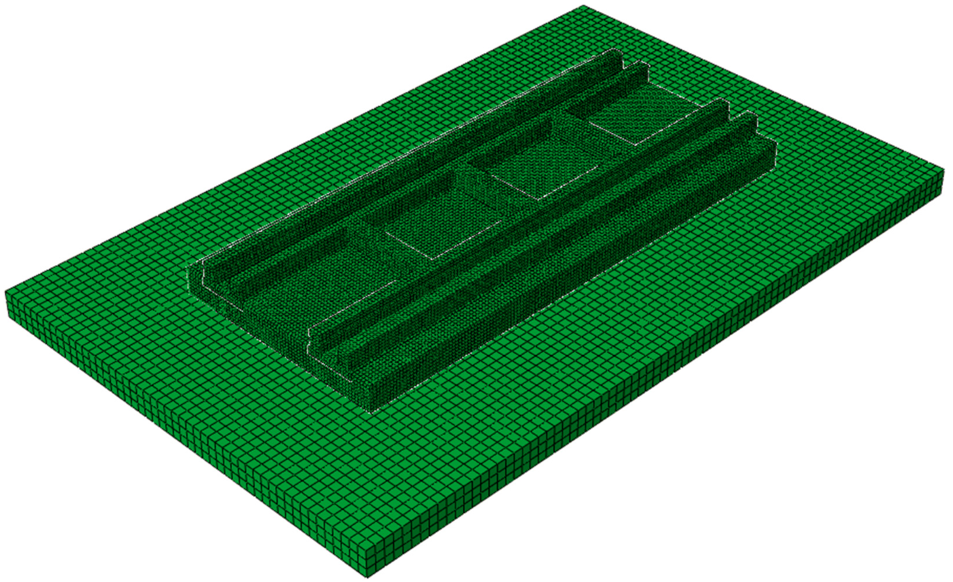
Table 2. Additionally, the model of the NFET was established using a general finite element software called ABAQUS, as shown in
Figure 4. The rails are simulated by the beam element, and the filling is simulated by the spring element Cartesian. The standard prefabricated rail seats, cast-in-place concrete, and subgrade are all simulated by solid elements [
20,
21,
22]. The rails are simulated by two elastic long beams, which are completely constrained at both ends. The wrapping material is simplified to point-supported linear springs, and each track slab is designed according to 10 sets of fastener nodes. The track slab below the fastener nodes is coupled to one fastener node and connected with the rail node by vertical spring elements. The binding constraint is set between the prefabricated rail seats and the cast-in-place concrete and between cast-in-place concrete and the subgrade. The bottom of the subgrade is completely constrained.
3.2. Load Values
3.2.1. Train Vertical Load
For the wheelset load, the most commonly used calculation method is called the quasi-static calculation method. The so-called quasi-static calculation method is to apply the basic principle of static calculation to the static calculation of the track structure, and then, according to the dynamic characteristics of the wheel-rail system, it is simplified as the dynamic increment problem of the wheel load [
23,
24]. Many countries in the world use the speed coefficient method to determine the vertical load of the train. It is believed that, when the train is running on the track, the dynamic effect between the wheel and the rail leads to the increase of the wheel load of the rail [
25]. However, the value of the speed coefficient varies from country to country. This paper adopts the calculation formula of vertical dynamic wheel load commonly used in China, as shown in Equation (1) [
26].
where
is vertical dynamic wheel load;
P is the static wheel load, the train axle weight is 12.5 t, and the single-strand rail static wheel load is 6.25 t;
is the speed coefficient, which can be calculated by the formula
, and the running speed is taken as 120 km/h, considering the later promotion and development of the trams;
is called the eccentric load coefficient of the curve segment, which is taken as 0, because the paper only considers the straight line interval. In summary, the train vertical load used for the finite element model calculation is 107.5 kN.
3.2.2. Uneven Settlement of Subgrade
The uneven settlement of the subgrade is actually the vertical uneven deformation along the longitudinal distribution of the track. There are various forms of subgrade settlement, and the models for simulating the uneven settlement of subgrade include the cosine type, staggered type, folded angle type, etc. [
27,
28]. When the ballastless track is located on the subgrade, the uneven settlement of the subgrade will cause additional force on the ballastless track. A common cosine half-wave curve, shown in Equation (1), is used for the simulation [
29].
where
is the uneven settlement value of the subgrade;
is the amplitude of the cosine type subgrade settlement, which is taken as 10 mm;
is the standard settlement length, which is taken as 20 m;
is the location where uneven settlement occurs;
is the starting position of the settlement.
3.2.3. Self-Weight Load
After the uneven settlement of the subgrade, the ballastless track structure will follow the settlement. NFET is covered with soil and greening above the track structure, and all track structures, except the top of the track, are embedded under the road pavement. The cast-in-place resin is generally used as a filler on both sides of the rail waist to ensure the geometric position of the rail in the service of the tram. Therefore, when the subgrade settles unevenly, it is necessary to consider the deflection of the track structure, due to its own weight.
3.3. Working Condition Setting
3.3.1. Beam Width
This section mainly carries out the design of beam width and propose six design schemes of 150, 185, 210, 240, 270 and 300 mm. Taking the 150 and 300 mm models as examples, as shown in
Figure 5, the rest of the schemes follow the same way of adding transverse connecting beams, and only the width of the beams changes. The finite element models of embedded track structures in different construction stages are established, respectively. The stress and deformation of the track structure are the control conditions. The stress and displacement differences between different design schemes are compared, the key parameters affecting the stress and deformation of the track structure are established, and the optimal design scheme is finally determined.
3.3.2. Thickness of the Lower Slab of the Rail Seats
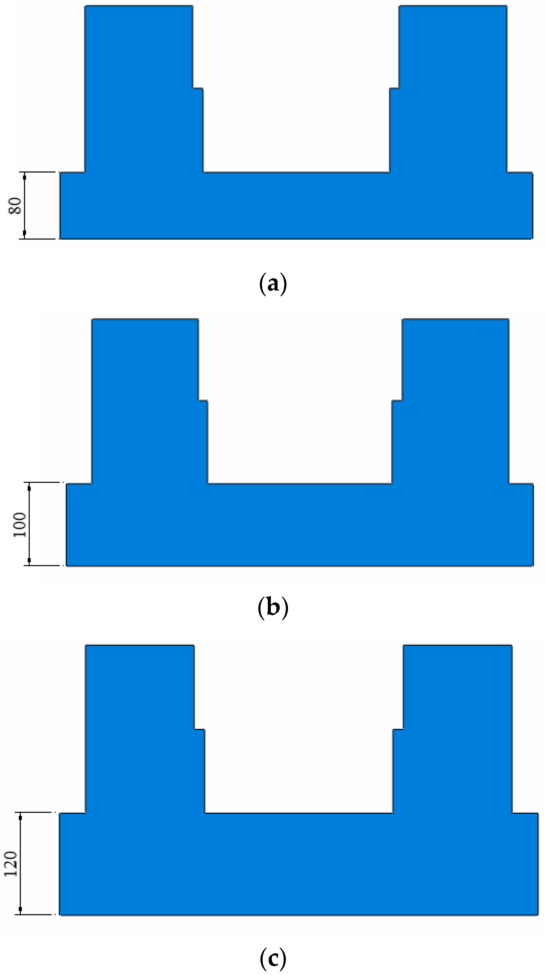
This section mainly carries out the design of the thickness of the lower slab of the prefabricated rail seats. Three design schemes of 80, 100 and 120 mm are proposed, as shown in
Figure 6. The stress and deformation of the track structure are the control conditions. The stress and displacement differences between different design schemes are compared, the key parameters affecting the stress and deformation of the track structure are established, and the optimal design scheme is finally determined.
3.3.3. Installation of Cable and Drainage Facilities
The drainage design of the tram project is mainly to remove the rainwater in the groove of the groove rails, the rainwater in the track area, and the seepage water in the track area of the green pavement section. Since the cast-in-place concrete layer is impermeable, the track bed of NFET is divided into several relatively closed areas. According to the safe driving requirements of modern trams, the wading depth of the track area cannot exceed the technical requirements of the vehicle. Under different operating speeds, the wading depth is inconsistent, but the safest operation method is that there is no water on the rail surface. Since the tram has no horizontal drainage slope on the straight section of the track surface, the rainwater in the track area can only be discharged in sections through the longitudinal slope of the line, which also requires that the drainage facilities of modern tram projects must be feasible.
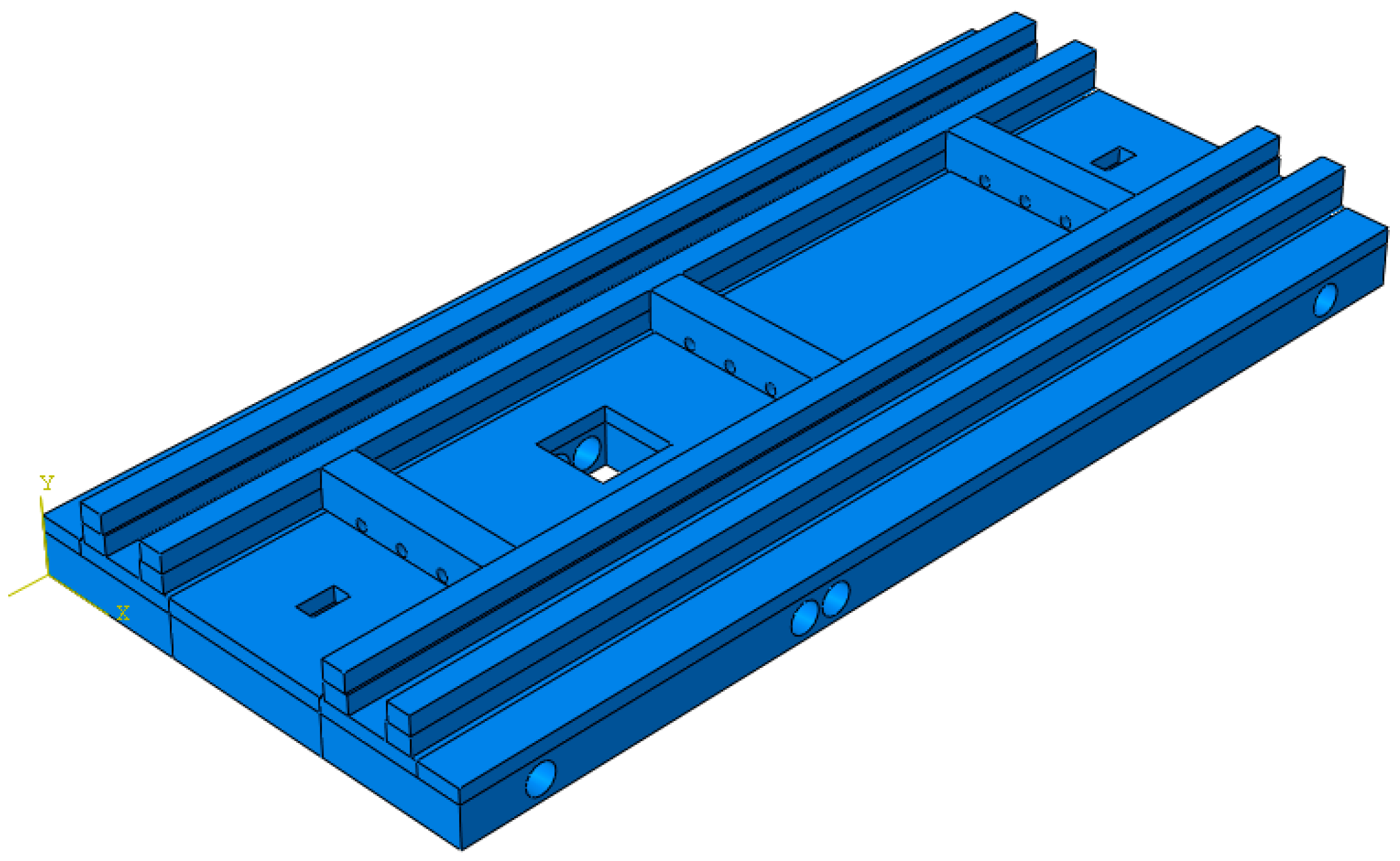
The setting method of the cable and drainage facilities of NFET is shown in
Figure 7, and the geometric parameters, such as the radius of the cable pipes, the passing position, and the position of the drainage well, are shown in
Table 1. This article only conducts the finite element analysis of the internal stress and deformation of the track structure in different construction stages for the two design schemes, with or without pipelines. By comparison, the influence of pipeline design on the mechanical characteristics of the track is studied, and the feasibility of the original design scheme is verified.
4. Comparison of Mechanical Characteristics of NFET Structure under Different Period Conditions
Due to the frame-type structure characteristics of NFET, its mechanical characteristics in the construction and operation stages are particularly worthy of attention. Through the comparative analysis of different working conditions, the optimal combination of the width of the NFET beams and the thickness of the lower slab of the rail seats is determined, and the feasibility of the design of the cable pipeline and drainage facilities can also be verified.
4.1. Calculation and Analysis of the Mechanical Characteristics of Each Design Scheme in Hoisting Stage
In the hoisting stage, the concrete has not been poured yet, and the NFET is suspended and fixed in the designated position. Therefore, the NFET structure mainly bears its own gravity at this stage. The deformation of the NFET structure, caused by its own weight, should be controlled to improve the accuracy of the track geometry adjustment. According to the on-site installation guidance of the track project, the track slab is vertically supported by eight ground anchor bolts using the pre-embedded casing on the prefabricated rail seats, and the pre-embedded casings are completely constrained. Since the track slab is a symmetrical structure, the displacement of the middle of the track (TM), the end of the track (TE), the point at the lifting holes (LHP), the tensile stress of the point at the first beam (1BP), and the point at the second beam (2BP) are analyzed. Since the NFET is a symmetrical structure, only two beams need to be analyzed. Therefore, 1BP and 2BP are selected sequentially from the end of the track to the middle of the track, same as below.
4.1.1. Beam Width Comparison
The displacement and stress of the NFET structure in the construction and hoisting period are shown in
Figure 8, where the TE displacement is actually in the negative direction.
According to
Figure 8, as the width of the beam increases, the displacement of the prefabricated rail seats of the NFET does not change significantly (not more than 10%). The stress at the LHP increases with the increase of the beam width, and the stress at the beam remains unchanged. The reason is that the increase in the width of the beam leads to more weight of the track slab, which contributes to the larger stress of the LHP, and it can also be proven by the the increment of the width of the beam and the stress of the LHP being the largest in the 150~185 mm section. During the construction hoisting period, the width of the beam has basically no effect on the stress at the beam, but it is the decisive factor for the stress of the lifting holes.
4.1.2. Thickness of the Lower Slab of the Rail Seats
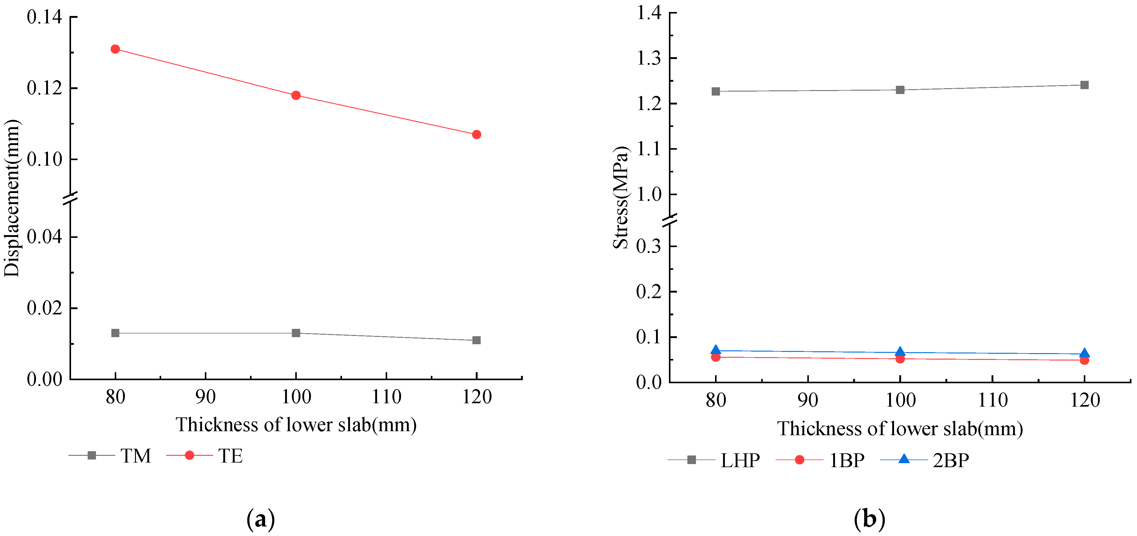
The stress and displacement of the NFET structure in the construction hoisting period are shown in
Figure 9, where the TE displacement is actually in the negative direction.
According to
Figure 9, as the thickness of the lower slab of the prefabricated rail seats increases, the displacement of the prefabricated rail seats at the TM does not change significantly, but the displacement at the TE decreases. The stress of LHP increases slightly with the increase of the track thickness, and the stress at the beam decreases slightly with the increase of the plate thickness. It can be seen that the thickness of the lower slab is not the controlling factor of the displacement and stress in this period.
4.1.3. Comparison of Cable and Drainage Facilities
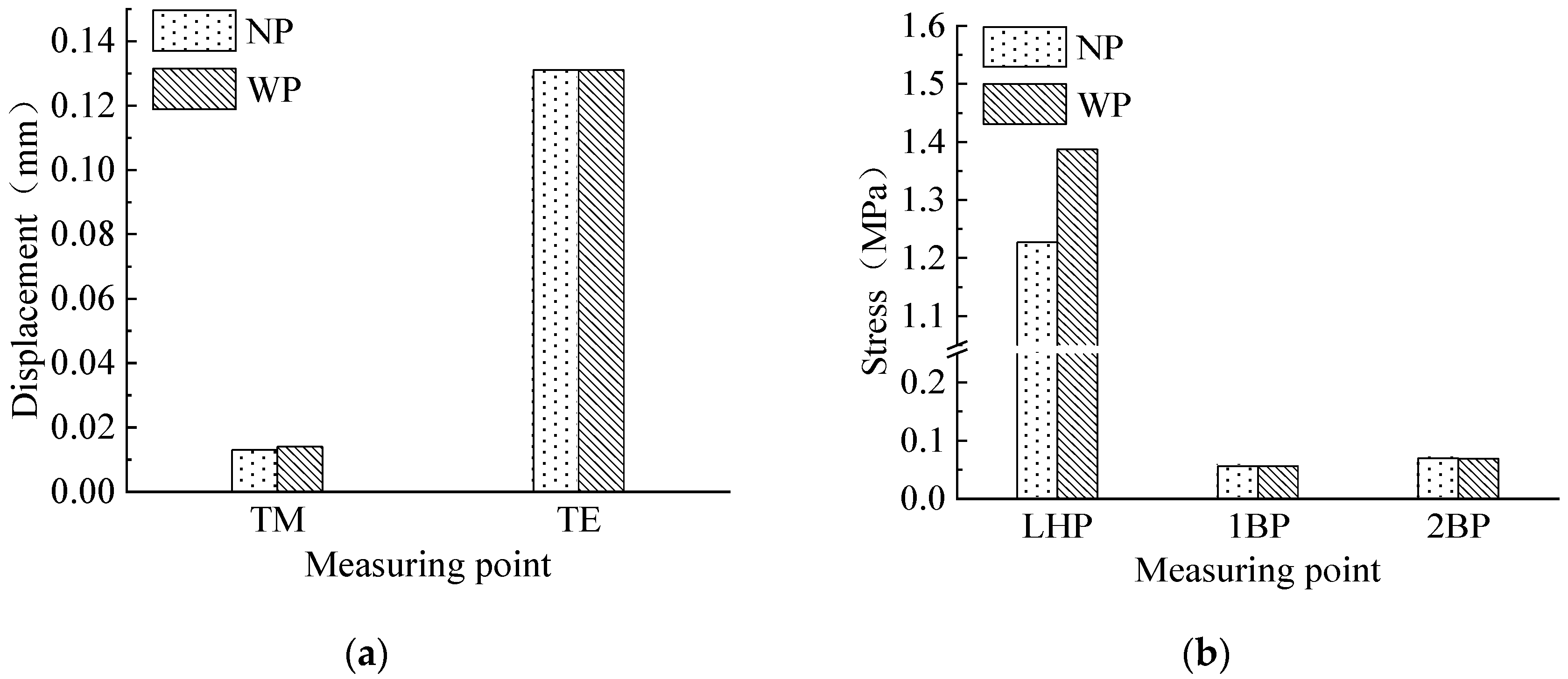
Figure 10 shows the stress and displacement of the NFET structure during the hoisting period, which shows the displacement and stress of the NFET under the structure without pipelines (NP) and the structure with pipelines (WP).
According to
Figure 10, when considering the pipelines, the LHP stress has increased by 13%, and the displacement and stress of other positions are basically unchanged. On the one hand, the gravity of the track slab in this period is borne by the LHP completely. Although the pipeline’s design slightly reduces its gravity, it aggravates the stress concentration, which, in turn, increases the stress of the LHP; on the other hand, due to the high rigidity of the track structure, under the condition of no additional load, regardless of whether the pipeline is considered, the track slab hardly produces vertical displacement.
4.2. Calculation and Analysis of the Mechanical Characteristics of Each Design Scheme in Running Stage
At this time, the NFET structure mainly bears the load of the tram, its own weight, and the weight of the green soil above the track. In the design process, the additional load of the track structure caused by the uneven settlement of the subgrade should not be included in the design load of the track structure for structural calculation, but regarded as an abnormal load with a small probability of occurrence in the track structure. It is considered as a check condition in the design of the track structure.
The model uses five track slabs for analysis. The tram load is transformed into a concentrated force, and a tram bogie is loaded. The front axle of the bogie is loaded at the middle of the track (TM), the fixed wheelbase is 1600 mm, and the single-wheel static load is 107.5 kN. The lowest point of settlement is set at the front axle of the bogie to explore the deformation and mechanical characteristics of the track structure under the uneven settlement of the subgrade.
The model selects the loading point of the bogie at the position in the plate of the No. 1 plate. The displacement measuring points of the No. ①–③ rail seats and cast-in-place concrete slabs are shown in
Figure 11. For the prefabricated rail seats, the vertical displacements of the six measuring points, shown in
Figure 11 (1 MP to 6 MP), as well as the stress of the bottom of the middle of the track (TMB), the upper part of the middle of the track (TMU), the bottom of the end of the track (TEB), the upper part of the end of the track (TEU), the point at the first beam (1BP), and the point at the second beam (2BP), were selected for analysis. For the cast-in-place concrete, the vertical displacements of the six measuring points, shown in
Figure 11, as well as the stress of upper part of the middle of the track (TMU), the bottom of the end of the track (TEB), the upper part of the end of the track (TEU), and the point where the settlement begins (SBP), are analyzed. Through the force analysis of different design schemes, the difference in the deformation and stress of the track structure under different design schemes is compared.
4.2.1. Beam Width Comparison
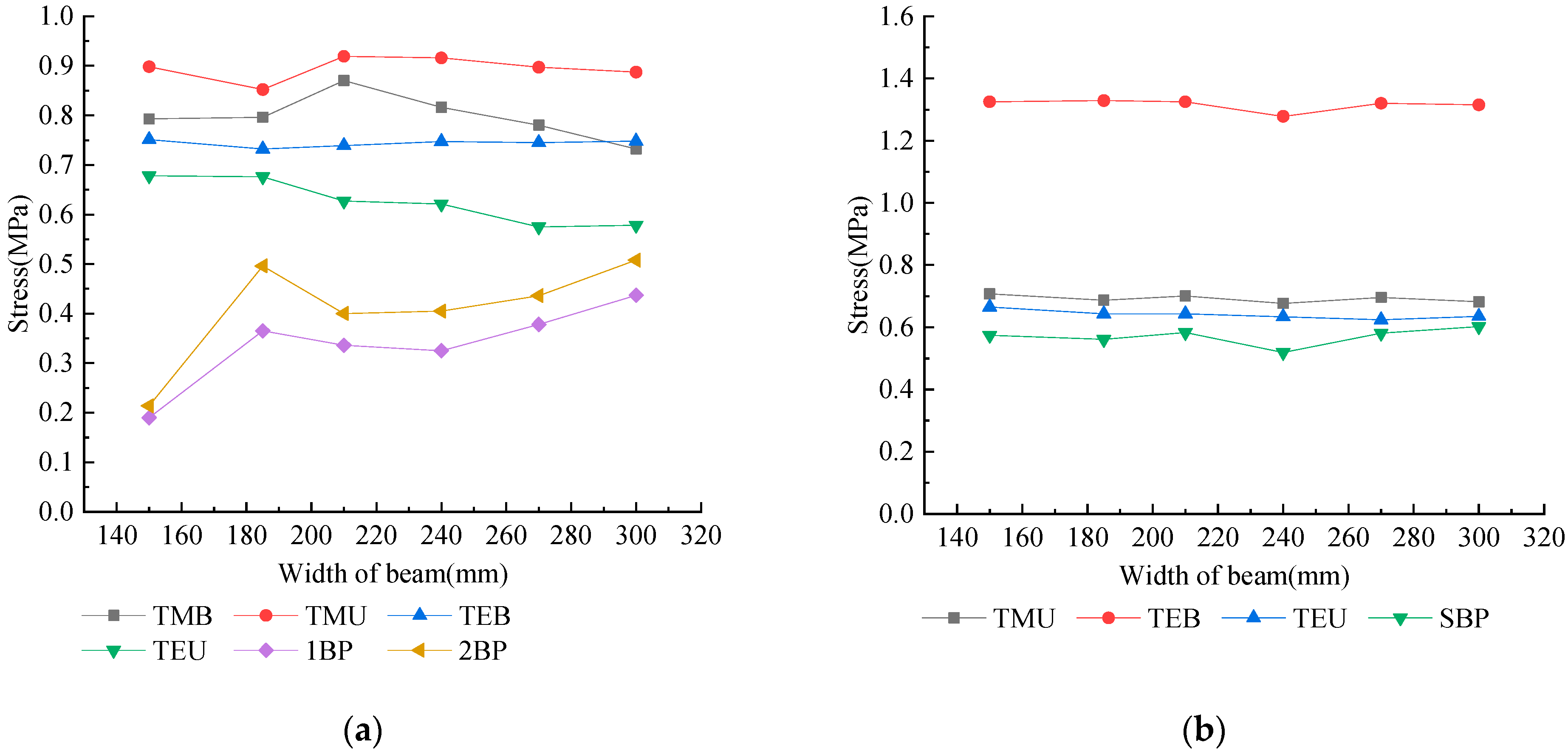
The displacement and stress values of each design scheme in the running period are shown in
Figure 12 and
Figure 13, respectively. The displacement of each measuring point is actually in the negative direction.
According to
Figure 12, considering the uneven settlement of the subgrade and the load of the tram, the vertical displacements of the bottom of the rail seats and the bottom of the cast-in-place concrete slab at the same measuring point are almost the same as each other. The reason is that, in this period, through the cementation effect of cast-in-place concrete, the coupling of the track slab is greatly improved and results in transforming into a systematic body. In addition, it can also be found that increasing the width of the beam will hardly change the displacement at each position of the structure, indicating that the width of the beam is not a controlling factor for the vertical displacement of the track structure in this period.
According to
Figure 13, the stress of the existing concrete structure is generally greater than the stress of the rail seats. For the rail seats, when the beam width is 150 mm, the stress at the beam is relatively small. When the beam width changes from 185 to 300 mm, the stress at each position does not change significantly, and the maximum stress appears in TMU; for cast-in-place concrete, TEB is the most dangerous point. The maximum stress is 1.33 MPa, the beam width is 240 mm, and the TEB and stress at the SBP are the smallest.
4.2.2. Comparison of the Thickness of the Lower Slab of the Rail Seats
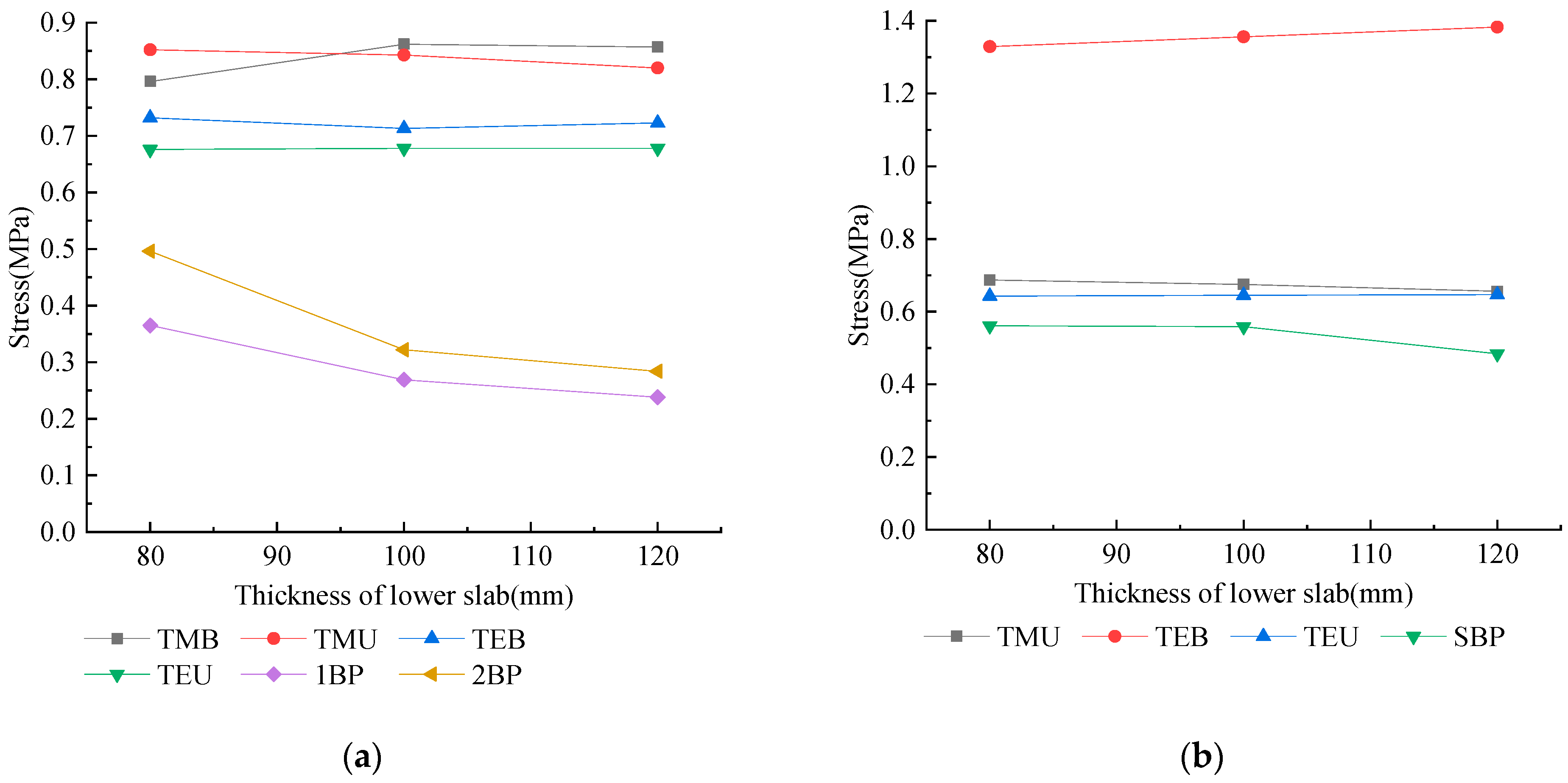
During the running period, the displacement and stress values of each measuring point on the track are shown in
Figure 14 and
Figure 15, and the displacement of each measuring point is in the negative direction.
According to
Figure 14, considering the uneven settlement of the roadbed and the load of the tram, the vertical displacements of the bottom of the rail seats and the bottom of the cast-in-place concrete slab at the same measuring point are almost the same. It is also due to the cementation effect of the cast-in-place concrete, which forms a common organic whole between the various components of the track. Consistent with the foregoing conclusions, the vertical displacement of the structure does not change with the thickness of the lower slab, indicating that the thickness of the lower slab in this period is not a controlling factor for the vertical displacement of the track structure.
According to
Figure 15a, it can be seen that, with the increase of the thickness of the lower slab of the rail seats, the stress at the two beams of the prefabricated rail seats continues to decrease, and the change between 80 and 100 mm is the most significant, with a decrease of 26.3 and 35.1%, respectively, and then flattened out with no obvious changes in the other positions. According to
Figure 15b, it can be seen that, with the increase of the thickness of the lower slab of the rail seats, the stress at each point of the cast-in-place concrete does not change significantly.
4.2.3. Comparison of Cable and Drainage Facilities
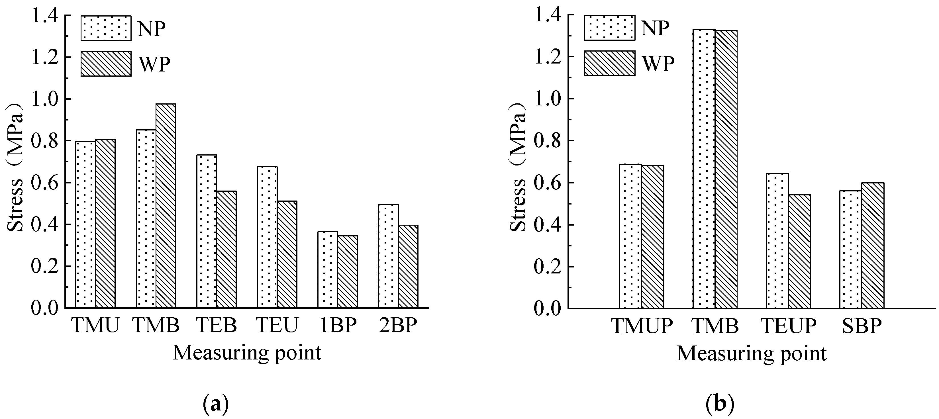
The displacement and stress of the bottom of the prefabricated rail seats and the bottom of the cast-in-place concrete are shown in
Figure 16 and
Figure 17, which shows the displacement and stress of the NFET under the structure without pipelines (NP) and the structure with pipelines (WP).
According to
Figure 16, it can be seen that, when the pipeline is considered under the uneven settlement of the subgrade and the load of the tram, the displacement of each position of the structure is almost the same as that when the pipeline is not considered. It shows that during the running period, the vertical displacement of the rail seats and the bottom of the cast-in-place concrete is hardly affected by pipeline design.
According to
Figure 17, it can be seen that, under the effects of uneven settlement of subgrade and tram load, for prefabricated rail seats, the stress at TMUP increased when the pipeline is considered, and the increase was 14.6%. However, the stress of the other measuring points were basically unchanged, or even slightly reduced, for cast-in-place concrete structures. The stress at TMB increased slightly when the pipeline was considered, and the stress at the SBP increased slightly by 4 and 6%, respectively. The stresses at the other measuring points remained unchanged, or even slightly reduced.
5. Discussion
According to the shortcomings of the existing tram track structure, a novel frame-embedded track (NFET) with transverse connecting beams has been developed. Through the establishment of a finite element model of the NFET, the static characteristics of NFET structure in two different construction stages were systematically analyzed with the beam width, the thickness of the lower slab of the rail seats, and the cable and the drainage facilities as the research variables.
In the hoisting stage, with the increase of beam width, the displacement of NFET structure did not change significantly, and the stress at the lifting hole increased continuously, but the stress at the beam remained unchanged. With the increase of the thickness of the lower slab of the rail seats, the displacement in the thickness of the lower slab of the rail groove did not change obviously, but the displacement of the plate end decreased; the stress at the lifting holes increased slightly, and the stress at the beam decreased slightly. When considering the cable and the drainage facilities, the stress at the lifting holes increased, while the displacement and stress at other measuring points remained unchanged. It can be seen that, at this stage, the thickness of the lower slab of the rail seats and the cable and the drainage facilities had no significant effect on the mechanical properties of the NFET structure. However, the width of the beam is the determining factor for the stress at the lifting holes.
In the driving stage, the vertical displacement of the same measuring point at the bottom of the rail seats and the bottom of the cast-in-place concrete slab was almost the same. It was not affected by the changes of the width of the beam, the thickness of the lower slab of the rail seats, and the cable and the drainage facilities. When the beam width was 150 mm, the stress at the beam of rail seals was small. When the beam width was 240 mm, the stress at the bottom of the cast-in-place concrete slab end and at the beginning of settlement reached the minimum. In particular, the stress of the cast-in-place concrete structure was generally greater than that of the prefabricated rail seats. With the increase of the thickness of the lower slab of the rail seats, the stress at the prefabricated rail seats beam decreased continuously and changed most significantly in the 80 mm~100 mm range, then tended to be gentle, and there were no significant changes in the other measuring points. When the cable and the drainage facilities are considered, the stress at the middle and upper parts of the prefabricated rail seats slab, the middle and bottom of the cast-in-place concrete slab, and the beginning of the settlement increased slightly, while the stress at other measuring points remained unchanged, or even decreased slightly.
Of course, the study also has some limitations. First of all, in terms of research methods, this paper only uses numerical simulation, and subsequent research can consider continuing to carry out model tests or physical tests on the basis of this paper. Secondly, in terms of research content, this paper only studies the static performance of an NFET structure under conventional loads and has not conducted in-depth research on its dynamic performance and some special loads (such as earthquake). Moreover, in terms of the scope of application, this paper only studies the feasibility of NFET structure in the tram field and its applicability in other rail transits, such as subway, high-speed railway, and heavy haul railway, remains to be discussed.
6. Conclusions
The following important conclusions can be obtained, which can be used as a reference for optimizing the design of the modern tram track structure:
As the width of the beam increases, the vertical displacement of the NFET structure does not change significantly. The LHP and TEB are the two most dangerous points in the whole construction process, and the tensile stress can reach more than 1.3 MPa. The former increases slowly, in the range of 185~240 mm, while the latter achieves the minimum value at 240 mm. Therefore, it is recommended that the design reference value of the beam width is 240 mm.
When the thickness of the lower slab increases by 20 mm, the displacement or stress of most of the measuring points of the NFET does not change much (within 10%), and the increase point and the decrease point are roughly equal in number. It is worth noting that the LHP stress will increase with the increase of the thickness of the lower slab and is close to the design value of the axial tensile strength of C35 concrete. Therefore, it can be considered that the stress state of the track structure has not been improved by increasing the thickness of the lower slab. At the same time, in order to save manufacturing costs and consider factors such as construction convenience, it is recommended that the design reference value of the lower slab thickness is 80 mm.
When considering the cable and the drainage facilities, the displacement increase is generally within 10%, but for stress, only three measuring points have an increase of more than 20%, and they are all safer points (the maximum is 0.976 MPa), indicating that the pipeline design is not the decisive factor of the displacement and stress of NFET. Therefore, it can be considered that the cable and the drainage facilities are not enough to destroy the original stress state of the NFET structure, and the pipeline layout in the original design scheme is feasible.
The stress of the rail seats is generally greater than that of the cast-in-place concrete. It is recommended that, when the NFET structure is adopted, the intensity of the cast-in-place concrete should be greater than that of the prefabricated frame structure. At the same time, in order to reduce the generation of clutch joints, it is recommended to take measures to control the shrinkage of cast-in-place concrete, such as choosing cement with low drying shrinkage and pouring in sections during construction.
7. Patents
Di Y.F.; Li D.; Dong C.Z.; Xu D.Z.; Yan H.J.; Cong Y.Y.; Gao S.L.; Li Z.T.; Wang W.D.; Yin H.T.; Zeng Z.P. A frame type embedded track structure. China Patent, Shandong Province, CN212771763U, 2021-03-23 (in Chinese).
Author Contributions
Conceptualization, Z.Z. and X.H.; methodology, Y.X.; software, D.W.; validation, A.A.S.Q. and W.Y.; formal analysis, S.B.H.; investigation, W.Y.; resources, Z.Z.; data curation, Y.X.; writing—original draft preparation, Y.X.; writing—review and editing, X.H.; visualization, D.W.; supervision, W.W.; project administration, W.W.; funding acquisition, Z.Z. All authors have read and agreed to the published version of the manuscript.
Funding
This research was funded by the Natural Science Foundation of Hunan Province, China, grant number 2019JJ40384; the Science and Technology Development Plan Project of China Railway Bureau 14 Group, grant number YGDC-30.
Institutional Review Board Statement
Not applicable.
Informed Consent Statement
Not applicable.
Data Availability Statement
All data, models, and code generated or used during the study appear in the submitted article.
Conflicts of Interest
The authors declare no conflict of interest.
References
- Shan, Y.; Wang, B.L.; Zhang, J.W.; Zhou, S.H. The influence of dynamic loading and thermal conditions on tram track slab damage resulting from subgrade differential settlement. Eng. Fail. Anal. 2021, 128, 105610. [Google Scholar] [CrossRef]
- Lakusic, S.; Bogut, M.; Tkalcevic Lakusic, V. Noise and vibrations at tram track intersection. J. Acoust. Soc. Am. 2008, 123, 3259. [Google Scholar] [CrossRef]
- Sikorski, P.; Wińska-Krysiak, M.; Chormański, J.; Krauze, K.; Kubacka, K.; Sikorska, D. Low-maintenance green tram tracks as a socially acceptable solution to greening a city. Urban For. Urban Green. 2018, 35, 148–164. [Google Scholar] [CrossRef]
- Lakušić, S.; Haladin, I.; Ahac, M. The effect of rail fastening system modifications on tram traffic noise and vibration. Shock. Vib. 2016, 2016, 1–15. [Google Scholar] [CrossRef]
- Leune, P.; Steen, E.; De Paepe, P.; Lyphout, C. An overview of tram tracks related cycling injuries in Ghent, Belgium. Traffic Inj. Prev. 2021, 22, 261–265. [Google Scholar] [CrossRef] [PubMed]
- Shan, Y.; Zhou, X.L.; Cheng, G.H.; Jiang, Z.Q.; Zhou, S.H. In-situ test on impact loads of a five-module 100% low-floor tram and the prediction of damage characteristics of a pile-plank-supported tram track. Constr. Build. Mater. 2021, 277, 122320. [Google Scholar] [CrossRef]
- Falamarzi, A.; Moridpour, S.; Nazem, M. A time-based track quality index. Melbourne tram case study. Int. J. Rail Transp. 2021, 9, 23–38. [Google Scholar] [CrossRef]
- Jozef, M.; Majercak, P.; Kurbatova, A.; Kurbatova, E. The operation of trams on a tramway track in Kosice, and their technical issues. IOP Conference Series. Mater. Sci. Eng. 2020, 918, 012152. [Google Scholar]
- Feng, Q.S.; Sun, K.; Luo, X.W.; Liu, Q.J.; Zhang, P.F. Longitudinal force analysis of tram embedded track on simply supported bridge. J. Railw. Eng. Soc. 2017, 34, 27–32. (In Chinese) [Google Scholar]
- Zeng, Z.; Huang, X.D.; Wang, J.D.; Liu, F.S.; Wang, W.D.; Shuaibu, A.A. Wheel–rail stochastic dynamics and rail wear analysis of small radius curved sections of a tram line based on generalized probability density evolution. Proc. Inst. Mech. Eng. Part F J. Rail Rapid Transit 2021, 235, 543–558. [Google Scholar] [CrossRef]
- Haladin, I.; Bogut, M.; Lakušić, S. Analysis of tram traffic-induced vibration influence on earthquake damaged buildings. Buildings 2021, 11, 590. [Google Scholar] [CrossRef]
- Sun, W.; Thompson, D.; Toward, M.; Zeng, Z.R. Modelling of vibration and noise behaviour of embedded tram tracks using a wavenumber domain method. J. Sound Vib. 2020, 481, 115446. [Google Scholar] [CrossRef]
- Shan, Y.; Wang, B.; Zhou, S.H.; Zhang, J.W.; Huang, A.J. Dynamic analysis of tram vehicles coupled with the track system based on staggered iterative algorithm. J. Comput. Nonlinear Dyn. 2020, 15, 061002. [Google Scholar] [CrossRef]
- Di, Y.F.; Dong, C.Z.; Yin, H.T.; Wang, W.D.; Zeng, Z.P.; Huang, X.D.; Wang, D. Research on optimal design of a novel frame embedded track structure for tram. Bull. Sci. Technol. 2021, 37, 103–108. [Google Scholar]
- Bethel Lulu, G.; Chen, R.; Wang, P.; Xu, J.M.; Chen, J.Y.; Fang, J.S. Random vibration analysis of tram-track interaction on a curve due to the polygonal wheel and track irregularity. Veh. Syst. Dyn. 2022, 60, 1125–1147. [Google Scholar] [CrossRef]
- Yang, X.W.; Guo, S.J.; Lian, S.L. An analysis of wheel-rail normal contact stress under 30 t-axle-load heavy haul train. J. China Railw. Soc. 2015, 37, 19–25. [Google Scholar]
- Gridasova, E.; Loktev, A. High frequency vibrations arising in system wheel-rail, part I: Mathematical modeling of the distribution stress in contact zone wheel-rail. IOP Conf. Ser. Earth Environ. Sci. 2020, 459, 062086. [Google Scholar] [CrossRef]
- Dai, G.L.; Su, M. Full-scale field experimental investigation on the interfacial shear capacity of continuous slab track structure. Arch. Civ. Mech. Eng. 2016, 16, 485–493. [Google Scholar] [CrossRef]
- Chinese National Standards GB 50010-2010; Code for Design of Concrete Structures. China Architecture & Building Press: Beijing, China, 2015. (In Chinese)
- Ren, J.J.; Li, H.L.; Cai, X.P.; Deng, S.J.; Wang, J.; Du, W. Viscoelastic deformation behavior of cement and emulsified asphalt mortar in China railway track system I prefabricated slab track. J. Zhejiang Univ. Sci. A 2020, 21, 304–316. [Google Scholar] [CrossRef]
- Zhu, S.Y.; Cai, C.B. Interface damage and its effect on vibrations of slab track under temperature and vehicle dynamic loads. Int. J. Non-Linear Mech. 2014, 58, 222–232. [Google Scholar] [CrossRef]
- Zhong, Y.L.; Gao, L.; Zhang, Y.R. Effect of daily changing temperature on the curling behavior and interface stress of slab track in construction stage. Constr. Build. Mater. 2018, 185, 638–647. [Google Scholar] [CrossRef]
- Liu, C.X.; Zhai, W.M. Elementary research on problem of slab’s intensity by means of finite element analysis. J. Railw. Eng. Soc. 2001, 1, 24–26. (In Chinese) [Google Scholar]
- Zeng, Z.P.; He, X.D.; Huang, X.D.; Wang, W.D.; Wang, D.; Qahtan, A.A.S.; Boumedienne, H.S. Numerical simulation research on mechanical optimization of a novel fastener type ballastless track (NFTBT) for tram. Appl. Sci. 2022, 12, 8807. [Google Scholar] [CrossRef]
- Chen, X.F.; Lou, P. Railway Engineering, 2nd ed.; China Architecture & Building Press: Beijing, China, 2017; pp. 210–213. (In Chinese) [Google Scholar]
- Zhang, P.F.; Luo, K. Railway Track Engineering; Central South University Press: Changsha, China, 2017; pp. 144–155. (In Chinese) [Google Scholar]
- Guo, Y. Effects of Differential Subgrade Settlement and Its Evolution in High-Speed Railways on Mechanical Performance of Vehicle-Track Coupled System; Southwest Jiaotong University: Chengdu, China, 2018. (In Chinese) [Google Scholar]
- Yin, H.T.; Zeng, Z.P.; Di, Y.F.; Wang, W.D.; Dong, C.Z. Research on design optimization of embedded track structure of tram in poor geological area. Bull. Sci. Technol. 2021, 37, 110–115. (In Chinese) [Google Scholar]
- Pei, G.S.; Gao, J.M.; Guo, Y. Influence of uneven subgrade settlement on track structure stress of tramcar on sharing road right. J. Railw. Sci. Eng. 2018, 15, 2772–2779. (In Chinese) [Google Scholar]
Figure 1.
Tram and track structure. (a) Tram and (b) track construction site.
Figure 1.
Tram and track structure. (a) Tram and (b) track construction site.
Figure 2.
Tram-embedded track. (a) Track structure cross-section and (b) track physical map.
Figure 2.
Tram-embedded track. (a) Track structure cross-section and (b) track physical map.
Figure 3.
Schematic diagram of NFET structure.
Figure 3.
Schematic diagram of NFET structure.
Figure 4.
Finite element model of NFET.
Figure 4.
Finite element model of NFET.
Figure 5.
Schematic diagram of different beam width structure. (a) Beam width 150 mm and (b) beam width 300 mm.
Figure 5.
Schematic diagram of different beam width structure. (a) Beam width 150 mm and (b) beam width 300 mm.
Figure 6.
Schematic diagram of the structure of the lower slab of the rail seats. (a) 80 mm, (b) 100 mm, and (c) 120 mm.
Figure 6.
Schematic diagram of the structure of the lower slab of the rail seats. (a) 80 mm, (b) 100 mm, and (c) 120 mm.
Figure 7.
The NFET model with the cable and drainage facilities.
Figure 7.
The NFET model with the cable and drainage facilities.
Figure 8.
Displacement and stress change trend under different beam widths during construction hoisting period. (a) Displacement and (b) stress.
Figure 8.
Displacement and stress change trend under different beam widths during construction hoisting period. (a) Displacement and (b) stress.
Figure 9.
Trends of stress and displacement under different lower slab thickness conditions during the construction hoisting period. (a) Displacement and (b) stress.
Figure 9.
Trends of stress and displacement under different lower slab thickness conditions during the construction hoisting period. (a) Displacement and (b) stress.
Figure 10.
Stress and displacement in the hoisting period of construction. (a) Displacement and (b) stress.
Figure 10.
Stress and displacement in the hoisting period of construction. (a) Displacement and (b) stress.
Figure 11.
Layout of track slab displacement measuring points.
Figure 11.
Layout of track slab displacement measuring points.
Figure 12.
The vertical displacement trend of the rail seats and the bottom of the cast-in-place concrete under the conditions of different beam widths during the running period. (a) Rail seats and (b) cast-in-place concrete.
Figure 12.
The vertical displacement trend of the rail seats and the bottom of the cast-in-place concrete under the conditions of different beam widths during the running period. (a) Rail seats and (b) cast-in-place concrete.
Figure 13.
The change trend of the cast-in-place concrete stress under different beam widths during the running period. (a) Rail seats and (b) cast-in-place concrete.
Figure 13.
The change trend of the cast-in-place concrete stress under different beam widths during the running period. (a) Rail seats and (b) cast-in-place concrete.
Figure 14.
The vertical displacement trend of the bottom of the cast-in-place layer under different lower slab thickness conditions during the running period. (a) Rail seats and (b) cast-in-place concrete.
Figure 14.
The vertical displacement trend of the bottom of the cast-in-place layer under different lower slab thickness conditions during the running period. (a) Rail seats and (b) cast-in-place concrete.
Figure 15.
The stress change trend of the rail seats and the cast-in-place concrete under different lower slab thickness conditions during the running period. (a) Rail seats and (b) cast-in-place concrete.
Figure 15.
The stress change trend of the rail seats and the cast-in-place concrete under different lower slab thickness conditions during the running period. (a) Rail seats and (b) cast-in-place concrete.
Figure 16.
The vertical displacement of the rail seats and the bottom of the cast-in-place concrete during the running period. (a) Rail seats and (b) cast-in-place concrete.
Figure 16.
The vertical displacement of the rail seats and the bottom of the cast-in-place concrete during the running period. (a) Rail seats and (b) cast-in-place concrete.
Figure 17.
The vertical stress of the rail seats and the bottom of the cast-in-place concrete during the running period. (a) Rail seats and (b) cast-in-place concrete.
Figure 17.
The vertical stress of the rail seats and the bottom of the cast-in-place concrete during the running period. (a) Rail seats and (b) cast-in-place concrete.
Table 1.
The main geometric dimensions of NFET.
Table 1.
The main geometric dimensions of NFET.
| Components | Geometric Parameter | Value (mm) |
|---|
| Prefabricated frame structure | Length | 5600 |
| Width | 2026 |
| Height | 280 |
| Beam | Length | 966 |
| Width | 185 |
| Height | 280 |
| Cable pipe | Radius | 80 |
| Center shaft | Length | 400 |
| Width | 400 |
| Height | 270 |
| Drainage pipe | Radius | 80 |
Table 2.
Track structure parameters.
Table 2.
Track structure parameters.
| Track Structure Components | Parameter | Value |
|---|
| Rail | Elastic modulus | 2.1 × 10⁵ MPa |
| Poisson’s ratio | 0.3 |
| Density | 7.85 × 10⁻⁹ t/mm³ |
| Wrapping material | Stiffness | 50 kN/mm |
| Prefabricated rail seat | Elastic modulus | 3.45 × 10⁴ MPa |
| Poisson’s ratio | 0.167 |
| Linear expansion coefficient | 1.0 × 10⁻⁵ |
| Density | 2.5 × 10⁻⁹ t/mm |
| Cast-in-place track slab | Elastic modulus | 3.25 × 10⁴ MPa |
| Poisson’s ratio | 0.167 |
| Linear expansion coefficient | 1.0 × 10⁻⁵ |
| Density | 2.5 × 10⁻⁹ t/mm³ |
| Publisher’s Note: MDPI stays neutral with regard to jurisdictional claims in published maps and institutional affiliations. |
© 2022 by the authors. Licensee MDPI, Basel, Switzerland. This article is an open access article distributed under the terms and conditions of the Creative Commons Attribution (CC BY) license (https://creativecommons.org/licenses/by/4.0/).


