Article

On Managing Knowledge for MAPE-K Loops in Self-Adaptive Robotics Using a Graph-Based Runtime Model

by
Adrián Romero-Garcés
1,
Alejandro Hidalgo-Paniagua
2,
Martín González-García
1 and
Antonio Bandera
1,*
1
Departamento Tecnologia Electronica, ETSI Telecomunicacion, University of Málaga, 29010 Málaga, Spain
2
Center for Excellence of C++, SCALIAN, 29007 Málaga, Spain
*
Author to whom correspondence should be addressed.
Appl. Sci. 2022, 12(17), 8583; https://doi.org/10.3390/app12178583
Submission received: 29 July 2022 / Revised: 21 August 2022 / Accepted: 24 August 2022 / Published: 27 August 2022
(This article belongs to the Special Issue Advanced Cognitive Robotics)

Abstract

:
Service robotics involves the design of robots that work in a dynamic and very open environment, usually shared with people. In this scenario, it is very difficult for decision-making processes to be completely closed at design time, and it is necessary to define a certain variability that will be closed at runtime. MAPE-K (Monitor–Analyze–Plan–Execute over a shared Knowledge) loops are a very popular scheme to address this real-time self-adaptation. As stated in their own definition, they include monitoring, analysis, planning, and execution modules, which interact through a knowledge model. As the problems to be solved by the robot can be very complex, it may be necessary for several MAPE loops to coexist simultaneously in the robotic software architecture endowed in the robot. The loops will then need to be coordinated, for which they can use the knowledge model, a representation that will include information about the environment and the robot, but also about the actions being executed. This paper describes the use of a graph-based representation, the Deep State Representation (DSR), as the knowledge component of the MAPE-K scheme applied in robotics. The DSR manages perceptions and actions, and allows for inter- and intra-coordination of MAPE-K loops. The graph is updated at runtime, representing symbolic and geometric information. The scheme has been successfully applied in a retail intralogistics scenario, where a pallet truck robot has to manage roll containers for satisfying requests from human pickers working in the warehouse.

1. Introduction

Robotics technology is currently spreading from the highly structured environments with well-defined use cases of large-scale mass manufacturing to a wider range of market domains. In contrast to the somewhat standard mechatronic systems used in industrial robotics, these new application areas demand robots to adopt many different mechanical forms and be equipped with specific sensors and actuators. They should also interact with different unstructured and dynamic environments, often sharing space and tasks with people. Furthermore, robots must be endowed with the particular functionalities required to accomplish the very specific use cases that each application area requires, but also fulfill non-functional properties such as safety or security. For deployment in these challenging scenarios, robots must be autonomous, but this autonomous capability must be revisited in order to have an effective impact on the adoption of robots.
Among the core technologies involved in increasing autonomy in robotic systems, one relevant topic is self-adaptation. If an autonomous robot is to be able to operate in a real world setting without any form of external control for extended periods of time, we can assume that, in the previously described scenario, it is mandatory that an autonomous robot can monitor the context, self-adapting its behaviour to perceived changes. A key concept behind adaptability is that of variability: robotic platforms heterogeneous in hardware, software, and capabilities; applications with different quality requirements and particularities, and several ways of adapting a robot for a given use case. In some sense, deploying robots in one of these new scenarios can be seen as a work of tuning the variability to end up with a final configuration (hardware/software/behaviour/safety-security-performance attributes) that suits the use case. Variability can be partly set at design-time by the manufacturers, engineers or users. But there is also a part of the variability that should be closed at runtime. This part will be resolved by self-adaptation and autonomous decision making. This approach implies the deployment of a strategy to discover this unconstrained variability, the runtime mechanisms to monitor the internal and external context information, and optimisation procedures to close, also at runtime, this remaining variability. The MAPE-K feedback loop [1] is a well-adopted model for managing autonomous decision-making and self-adaptation.
The MAPE-K loop is a classic control structure in autonomic computing. After dividing up the system into a managed system and an adaptation engine, it defines a loop consisting of four steps; Monitoring, Analysis, Planning, and Execution. All these steps operate on the basis of a common knowledge base, which guides the behaviour of the robot at each step of the loop. The first step of the MAPE loop is the monitoring of the controlled system. The aim is to collect data about the state of the managed system. It is relevant to note that, for executing a task, the system will require in-depth knowledge to understand when, where, what, and how to do it. Captured data can be enriched to become a reusable piece of knowledge. In any case, the existence of a knowledge gap between the internalised concepts and those needed to solve the task may result in the task not being correctly solved. Cognition can be used to bridge this gap by modelling, applying, and learning domaindependent contextual knowledge [2]. In the Analysis step, the representation of the world is processed to determine the conditions required to trigger specific adaptation actions. The Planning step uses the inferred symptoms, as well as the policies defined at design-time, to define the intermediate actions to be implemented on the system. The Execution step is in charge of implementing the planned actions using the available resources.
A single MAPE loop is not always a sufficient solution for managing complex adaptations [3]. In the software architecture controlling the robot’s behaviour, several loops will run in parallel in order to satisfy several goals (e.g., detecting and locating a roll container, meanwhile approaching in order to pick it up), all of them necessary for completing a task. In these scenarios, the scheme must be extended for supporting intra-loop and inter-loop coordination. Intra-loop coordination will enable MAPE computations within one loop to be coordinated. Inter-loop coordination will enable MAPE computations across multiple loops to coordinate with one another. This will allow the MAPE computations of different loops to coordinate the various phases of adaptations. On the other hand, as it was pointed out by Giese et al. [4], the MAPE scheme must be slightly extended when runtime models are considered. A runtime model is a dynamic knowledge base that, in our case, can abstract useful information about the robot and its operational context. Thus, the runtime model augments the information available at design-time with information captured at runtime. This allows a system to successfully operate in a dynamic context [4]. This paper proposes to deal with both initiatives by implementing a runtime model as an internal representation including symbolic and metric information. The Deep State Representation (DSR) [5,6] is a multi-labelled directed graph that holds symbolic and geometric information within the same structure. Symbolic tokens are defined as logic attributes related by predicates that are stored within the graph in nodes and edges. Geometric information is stored as predefined object types linked by 4 × 4 homogeneous matrices. This information is also stored as nodes and edges of the graph. In our proposal, the DSR is a unique representation shared and updated by all software agents in the architecture. Synchronisation in the representation is addressed by means of messages that are annotated in the DSR [6]. At the perceptive level, nodes/edges are only updated by specific agents—this mapping is established at design time: for instance, only the PersonDetection agent can annotate in the DSR that the robot is detecting or not detecting a person or group of people. At the deliberative level, the decision-making agents annotate messages in the DSR that allow the other decision-making agents to know what the current running action and its execution state are.
Thus, we can affirm that all steps from the MAPE loop are simultaneously running. The software agents in charge of detecting obstacles or people or updating the battery value are always updating the model (by modifying the values on nodes or edges or by adding new items to the graph). Using this (internal and external) contextual information, other software agents will estimate non-functional properties, such as safety or performance. Estimated as Quality-of-Service metrics, their values will be also annotated in the DSR. Thus, raw context values and estimated QoS metrics will be available to all task-based agents present in the architecture and, together with information about subgoals and actions, they constitute the basis for allowing intra- and inter-loop coordination. The Plan step will monitor the evolution of the context for suggesting modifications to the deliberative course of action, but this evolution will also modulate the behaviour of more reactive agents. The goal is to synchronize the activity of all agents in the architecture through the annotations on the DSR.
The rest of the paper is organized as follows: Section 2 discusses related work on knowledge representation for robotics that can help their self-adaptation, focusing on those graph-based representations combining semantics and geometric concepts. Section 3 presents the DSR as a runtime model. Moreover, we will show how the DSR supports coordination of MAPE loops. The whole MAPE-K framework is described in Section 4. This section introduces the definition and interaction of the MAPE loops through the DSR. Section 5 provides details about our instantiation in the intralogistics domain. Experimental results are presented in Section 6. Finally, conclusions and future work are drawn in Section 7.

2. Related Work

When designing an autonomous robot, ideally it should be directed by our commands, planning its actions and executing a sequence of tasks whose aim is to achieve the desired result [7]. To achieve this, we must endow the robot with some kind of knowledge, which allows it to perform these steps. If the knowledge representation is not able to cope with a relevant part of the variability that the context can introduce (something difficult to complete when people must be considered as part of this context), the robot will be strongly tied to a single view of the reality, and will not be able to respond appropriately to events not considered in a nominal course of action. Defining at development-time a representation that will be able to continuously exhibit good performance at runtime is practically impossible. It is then highly desirable that the representation will be able to abstract useful information about the outer environment and about the robot itself, and that this can be continuously updated during execution.
A self-adaptive system is the one that, when a change in the system itself or in the environment occurs, is able of changing its behaviour, structure, and/or internal parameters autonomously. To help a robot to unfold this behaviour, the knowledge representation must be able not only to manage information about the robot’s actions and environment, but also to relate the semantics of these concepts to its internal components for decision making. For bridging the gap between the knowledge descriptions and the knowledge specifications about the implementation of the software solving tasks, Hochgeschwender et al. [8] proposed a graph-based knowledge representation. This graph is the basic tool for storing, composing, and querying domain models.
Graphs are a very popular tool for representing knowledge in robotics due to its simplicity for managing the information and its powerful capability to display us this information [7]. They can easily tie together high-level knowledge and low-level features or attributes. This is specifically true for semantic graphs, whose nodes and edges describing semantic concepts and details can be also related with spatial or geometrical information. For instance, in the proposal by Dang and Allen [9], semantic grasps and semantic affordance maps are introduced. Semantic grasps are generated using an example-based planning framework. These stable grasps are functionally suitable for specific object manipulation tasks. Then, semantic affordance maps relate local geometry to a set of predefined semantic grasps, appropriate to different tasks. The aim is to estimate the pose of a robotic hand with respect to the object for achieving the ideal approach direction required by a particular task.
The idea of extending the spatial information with semantic knowledge in the domain of robot navigation was present in the proposal by Galindo et al. [10]. In this work, the authors define a semantic map that integrates hierarchical spatial information and semantic knowledge. These semantic maps allow the planner to extend its capabilities by adding semantic information to the reasoning procedure. Similarly, semantic object maps [11] integrate semantic and geometric data for determining whether an action can be executed given the current state of the environment. Singh Chaplot et al. [12] propose topological representations for space where nodes store semantic features and edges provides coarse geometric information. Chen et al. [13] describe the environment as a graph of audio-visual waypoints (nodes). In the Topological Scene Map (TSM) [14], a behavioral topological map and a scene graph are combined. The behavioral topological map defines the spatial connection relationships, and semantically describes the navigation behavior between adjacent topological nodes. On the other hand, the scene graph promotes the TSM to record the objects detected in the scene and the relations between objects. Armeni et al. [15] view the 3D Scene Graph as a layered graph, with each level representing a different entity: building, room, object, and camera. The graph is created offline, using object detection over RGB images. The representation has been extended for managing dynamic entities. Thus, the 3D Dynamic Scene Graph (DSG) [16] is a spatial representation that integrates geometry and semantics of a scene at different levels of abstraction. The DSG models objects, places, structures, and agents and their relations, and is organized into a layered, directed graph. In this graph, nodes represent spatial concepts (e.g., a room or an object) and edges represent pairwise spatio-temporal relations (e.g., “person A is in room B at time t”). The graph is also created in an offline fashion, i.e., without satisfying real-time requirements, a requisite that is fundamental for real-world applications. Wu et al. [17] propose SceneGraphFusion, an approach to incrementally build up a semantic scene graph from a 3D environment given a sequence of RGB-D frames. An attention mechanism is considered for dealing with partial and missing graph data. Hydra is a real-time Spatial Perception System, able to build a 3D scene graph from sensor data in real-time [18]. The framework includes approaches for (i) capturing a local Euclidean Signed Distance Function (ESDF) around the current robot location, (ii) extracting a topological map of places from the ESDF, and (iii) segmenting the places into rooms. The framework also considers loop closure detection and optimization in 3D scene graphs. With the aim of effectively endowing a mobile robot with the ability to create 3D scene graphs, Bavle et al. [19] propose the Situational Graph (S-Graph), which combines in a single optimizable graph, the representation of the environment together with the robot pose. The S-Graph is online built in real-time, and it includes a robot tracking layer where the robot poses are registered, a metric-semantic layer with features such as planar walls, and a topological layer constraining the planar walls using higher-level features such as corridors and rooms.
In the recent literature, many proposals use CNNs (Convolutional Neural Networks) to recognize semantic properties in images and combine these results with topological maps [20,21,22,23]. We also use this scheme for adding and updating the information related with the outer world in the DSR. Specifically, and as in other previous work [24], we employ a pre-trained CNN and customize it through transfer learning to recognize people and roll containers in the video stream provided by an RGBD camera. However, our graphs also store information about the internal context (e.g., battery level) and about the collection of actions that the robot can perform. Section 5 provides more details about the objects of interest in our scenario and the information stored in our graphs.

3. Extending the MAPE Scheme: The DSR

3.1. The Deep State Representation

The Deep State Representation (DSR) is a multi-labelled directed graph that holds symbolic and geometric information within the same structure. Figure 1 shows one simplified example. The robot and the roll container are geometrical entities, linked to the world node (a specific anchor providing the origin of coordinates) by a rigid transformation. At the same time that we can compute the metric relationship between robot and roll container ( R T 1 × R T ), this roll container can be located close to the robot, and hence, the robot can launch the procedure for picking it up. In parallel, an agent can annotate that people are not_detected close to the robot. Features, such as the level of the battery, are annotated as properties of the specific node linked to the robot. Context features, or more elaborated perceptions obtained from them, are updated at runtime.
This simple example shows that all agents in the software architecture (navigation, person-related perception...) use the DSR for sharing information about specific parts of the context, creating a whole view of the current state. Furthermore, it also stores a complete view of the activities being performed by the robot, joining perceptions and actions within a shared structure. Details are annotated in nodes and arcs. For instance, a battery node has an internal level value, which will be updated by a specific agent in the software architecture.
In addition to the update of the DSR, the agents in the software architecture will read the DSR to search for those changes that trigger their specific task-solving skills. This mapping between changes in the DSR and actions is encoded within each agent. For instance, when a goal pose is set, the Navigation agent traces a route and moves the robot to this pose. In the internal grammar of each agent, rules are encoded as triplets with the states of the DSR after, during, and before the agent executes a specific action. For more details about the DSR, please see the work by [5,6]. Next, we extend the idea of using the DSR as a runtime model or as a mechanism for synchronizing running MAPE loops.

3.2. The DSR as a Runtime Model

In our software architecture, the DSR is the core item, storing all the information shared among the agents in the architecture. Thus, events, such as the detection of a person or the roll container, the presence of close obstacles, or the evolution of the battery level, are annotated in this graph. Moreover, we can also see in the DSR if the robot launched the picking up of the roll container, and is now approaching the roll container. There will be information annotated from the beginning (design-time), but also updates provided at runtime. Following the work by [4], we can state that the described DSR is a runtime model.
Definition 1.
A model is characterized by three elements: an original the model refers to, a purpose that defines what the model should be used for, and an abstraction function that maps only purposeful and relevant characteristics of the original to the model.
In our case, the original to which the model refers to is a real robot working in a retail scenario. At design-time, we can have at our disposal a grid-based map of the environment, a distribution of picking areas, or the features of the robot. The original also includes a mission manager that, in this case, collects the needs from the human pickers (requiring an empty roll container or asking for a loaded roll container to be moved to a different position). The purpose of our model is to allow the robot to satisfy these missions, but also to take into consideration the fulfilment of certain non-functional properties. For instance, unsafe situations must be proactively avoided. As described in [6], the DSR manages perceptions and actions within the same representation. Thus, the model covers physical properties of the robot and the environment, but also the current behaviour of the robot with respect to the current goals and the context. The purpose of the model is then to centralize all the information the robot needs to achieve a mission, including that related to the synchronization of the decision making modules running in the system. Details will be provided in next Sections.
With respect to the abstraction of the context, relevant information about the robot (battery level, payload, etc.) is annotated by different perception modules in the DSR. In a robot-centric view, its maximum speed or the algorithm employed for localization are autonomously chosen according to parameters such as the presence of close obstacles or people, or to the uncertainty on its pose. Non-functional properties are encoded as QoS metrics and also annotated and updated in the model, and then considered for tuning these parameters. The representation of the environment includes the location of static entities but also the presence of dynamic ones, such as people or roll containers. The model also describes the current behaviour of the robot with respect to the current goals and the context. Significantly, and contrary to the example in [4], we maintain an unique runtime model storing all the information related to structural context and behaviour.
Definition 2.
A runtime model is a model that complies with Definition 1 and, in addition, part of its purpose is to be employed at runtime and its encoding enables its processing at runtime.
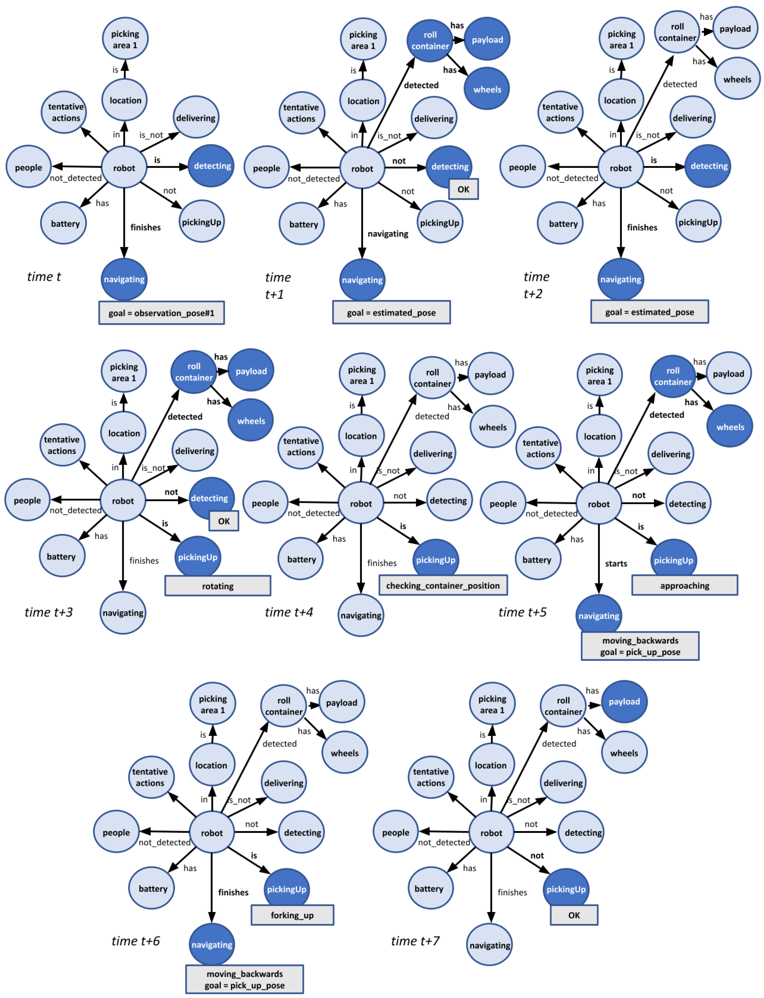
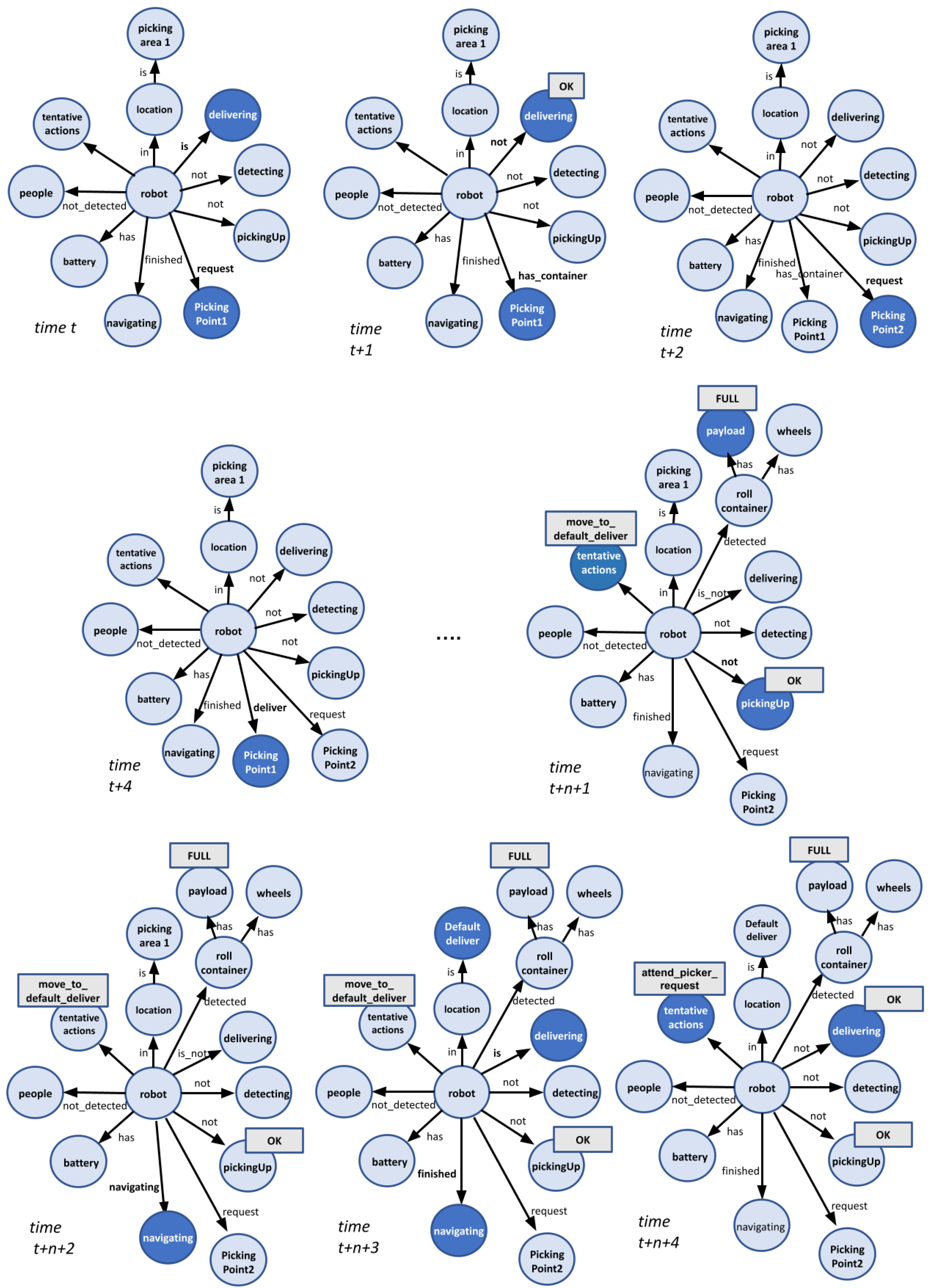
Being updated by all agents in the software architecture, the DSR is a runtime model that describes the as is situation on the whole running system [25]. Thus, it is a descriptive model of the system and environment. Figure 2 shows how the DSR evolves in a real trial. For the sake of clarity, we have further simplified the DSR representation with respect to Figure 1, leaving only the nodes that we consider most significant for the presentation of this example. The DSR, at time t in the figure, illustrates when the robot arrives to the picking area 1 where the human picker has left a roll container to be picked up and moved to a new delivering area. The request from the picker is managed as a goals set for the navigation agent, and also for the fork (lifting or lowering the container). Thus, the robot initially arrives at the observation pose #1 (in picking area 1). When the robot arrives at the desired picking area, the decision maker wakes up the agent in charge of detecting the roll container (the robot is detecting). This agent gives an ACK message by changing the link from starts to is (time t) and, if the container is detected, an internal result value in the detecting node is set to OK (time t + 1 ). A roll container node is then added to the representation, and its position on the map is annotated in the DSR (see time t + 1 ). The detection procedure finishes and the robot approaches to an estimated roll container pose (the new goal is set in the navigating node). Then (time t + 2 ), the detection procedure performs one last check, just to be sure that the roll container has not been moved. At time t + 3 the robot starts conducting the picking up task. As is shown in Figure 5, the robot has the fork placed in its backside, so the pickingUp agent rotates the robot 180 degrees (rotating) and checks the position of the wheels of the roll container (time t + 4 ) in order to estimate again the goal position. Then, the new action to be conducted for addressing the picking up task is to approach to the roll container (approaching, see time t + 5 ). A new pose is annotated as goal for the navigation agent, and the decision maker asks the robot to start navigating, moving backwards. Finally (time t + 6 and t + 7 ), the robot forks up the roll container and is ready to deliver it. As will be detailed in Section 4, this scheme does not imply that agents must be necessarily awakened by the deliberative module. Reactive agents in the architecture are always active. Thus, topics such as the level of the battery or the presence of people are always updated by specific agents in the architecture. As it is described in Section 4, the modules involved in the estimation of alternative actions to the current running one are also always updating the DSR (the tentative actions node in the figure). Specifically, in our use case, four actions are evaluated: to pick up the container, to return to the starting pose, to move to the charging station, and to deliver the container to the delivery pose set in the store. All these actions are weighted and these weight values are available in the DSR. As it is shown in Figure 3, these values allow the system to modify the course of action by itself when required.

3.3. The DSR as the Place for Coordinating MAPE Loops

Figure 2 exemplifies how the DSR is employed by the software architecture for coordinating the activity of their agents. The internal coordination of the MAPE loop involving the high-level deliberative module is achieved by annotating in the arcs linking the robot with tasks such as navigating, detecting, or picking up. In the example, all launched tasks were successfully reached. But this is not necessarily true for all trials. In Figure 3, the robot detects the roll container but, then, the agent in charge of detecting people modifies the DSR as several people surround the container. The situation is unsafe, and one analyzer agent annotates as tentative action to abort the picking up task. The procedure describing how this recommendation is generated is detailed in Section 6. But what is relevant here is that the decision maker reacts to this new reality by changing the course of action and aborting the task.
Figure 2 also illustrates how two loops interacts using the DSR. The picking up task involves several agents as they need to check the roll container position and approach it before picking it up. Checking the roll container position and approaching activities are coordinated using the information in the DSR, and the internal state of this task is also informed to the MAPE loop involving the high-level deliberative module. Thus, if a problem forces the picking up task to be aborted, the information is also managed by the deliberative module for adapting the course of action and, for instance, asks the robot to navigate to a new picking area for picking up a different roll container. Being one of the major novelties of this paper, Section 4 provides more information about how our MAPE loops interact using the information stored in the DSR. In this Section 4, we describe how the MAPE-K framework is organized and how the decision makers synchronize their plans or modify them according to changes in the context.

4. The Proposed MAPE-K Architecture

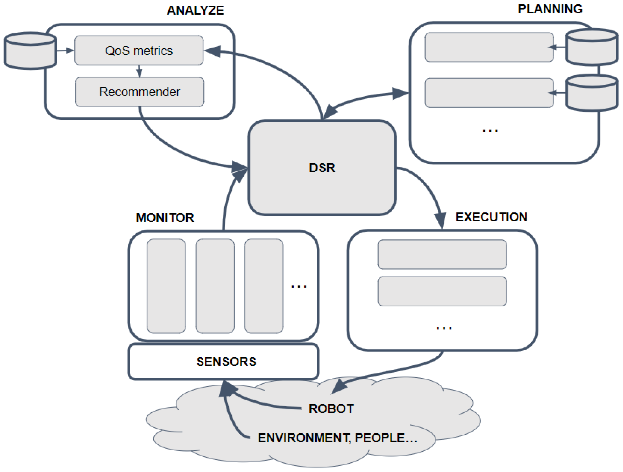
Figure 4 provides an overview of the implemented MAPE-K architecture. The system orbits around the DSR, a reflection model [25] where all the descriptive information needed to carry out the correct execution of the missions is stored. Part of this information is perceptive information coming from the sensors and preprocessed by different agents. They provide the Monitor step of our proposal. Sometimes this information is raw data (e.g., battery level or the lower distance to obstacles), sometimes it is symbolic data, usually obtained from binary observations or from the simple evaluation of geometric data (e.g., a roll container has been detected and is close to the robot). In all cases, this information is descriptive.
The Analyze step aims to monitor the DSR for recommending alternative actions to the decision making module. The scheme encodes non-functional properties (e.g., safety or punctuality) into Quality-of-Service metrics. Using context information and these metrics as inputs, a recommender quantifies what the best next action to be launched by the high-level decision maker should be. These recommendations are filtered by considering temporal causality and for avoiding erratic behaviours (e.g., cyclically categorizing a situation as safe or unsafe because the robot senses, sometimes yes and sometimes no, a person moving in front of it). Once filtered, the tentative actions are annotated in the DSR (we can see the node associated to these actions in the simplified views of the DSR in Figure 2 and Figure 3). The deliberative module will take into consideration these recommendations, modifying the course of action when necessary. Both the process of estimating QoS metrics and obtaining recommendations are based on fuzzy logic.
As the figure shows, several decision-making modules can coexist in our architecture. They use the information stored by the previous Monitor and Analyze steps for selfadapting the behaviour of the robot to the internal and external context. In our case, we have encoded the use cases into Behaviour Trees (BT) and these decision makers are the software modules in charge of managing their execution. These BTs can be extended with alternative branches for dealing with variability [26]. As illustrated in Figure 2 and Figure 3, these BT Executors need to coordinate their activities, and they do that by sharing information in the DSR. Section 5 provides more details about our implementation and instantiation in the intralogistic domain.

5. Implementation

5.1. The CARY Robot

In the real deployment of the proposal, we have employed the CARY robot from Metralabs GmbH. This robot can manage the typical roll containers, moving them from one picking position to another if this is required by a human operator. Roll containers will be moved to a general delivery pose set in the store if there is not a new request or when the roll container is full. Figure 5 shows the robot approaching to a roll container, picking it up, and moving in a real scenario. The robot detects the container using a camera placed in its frontside. When it rotates for picking up the container, fine grained detection is conducted using a laser range finder placed in its backside (at the front of the fork). For navigating in narrow corridors, it uses the four laser range finders in the frontside.

5.2. Software Architecture

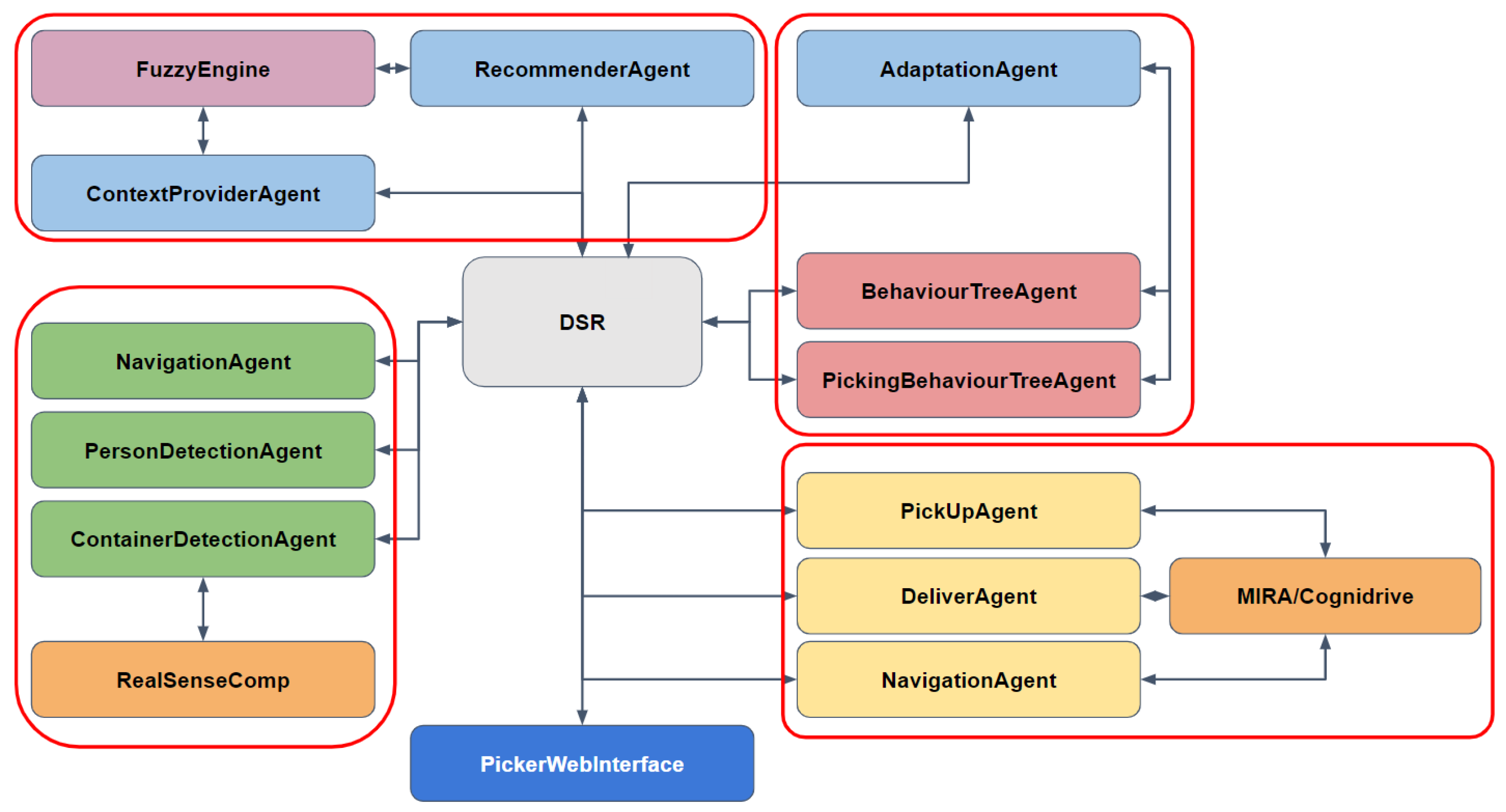
The instantiation of our system architecture in the intralogistics scenario is shown in Figure 6. In the Monitor step we have three major modules involved. The NavigationAgent is responsible for annotating in the DSR information related to the navigation and localisation framework. In this step, the information is related with the battery level and also with the presence of close obstacles, reaching a goal, or bumping with an obstacle. The PersonDetectionAgent and the ContainerDetectionAgent are in charge of annotating in the DSR the presence and location of people and roll containers, respectively. The framework was built using “You Only Look Once” (YOLO v3) and included within a Neural Compute Stick 2 (VPU from Intel), using the OpenVINO framework. For dealing with both tasks, images were captured using the Intel Realsense camera mounted in the robot.
The Analyze step consists of three relevant modules. The ContextProviderAgent is the responsible of collecting information about the context from the DSR, fuzzying it, and providing these topics to a first fuzzy inference engine implemented in the FuzzyEngine. This engine generates high-level metrics related with non-functional properties (safety, mission_completion or power_autonomy), and has been designed using the FuzzyLite Libraries for Fuzzy Logic Control [27]. In the FuzzyEngine, a second inference engine uses these metrics, and the temporal evolution of the state of the world, for quantifying the relevance of the collection of tentative actions that the robot can perform (e.g., abort the mission and move to the Charging station). The weights associated to each tentative action is updated in the DSR by the RecommenderAgent.
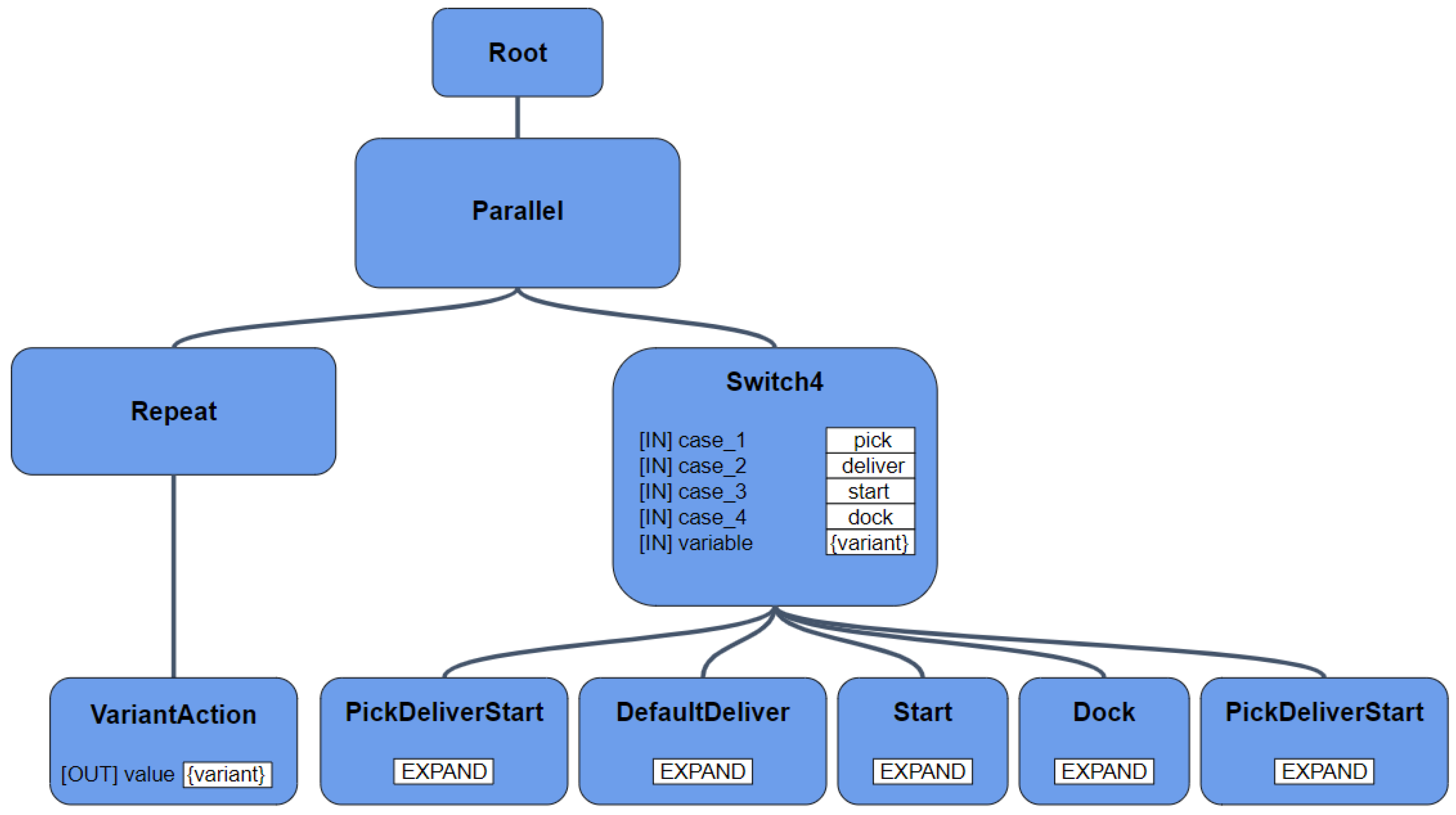
Having taken the temporal evolution of these weights into consideration, the AdaptationAgent is the responsible for triggering a change in the course of action. To achieve this, this agent is linked to the decision makers. When the current action is stopped for executing a new one, it is the responsibility of the DSR update to maintaining the coordination among agents. At the Planning step, the course of action is mainly encoded in the CARY robot using the Global Management BT, responsible for the robot behaviour at a mission-level, and the PickUp Management BT, which allows the system to monitor the detection of the roll container and to autonomously move the robot to an alternative pose if the initial procedure fails. The Goal Management BT manages the requests of the human pickers, but it is possible, for instance, to abort a mission if the power autonomy is quickly decreasing or if the situation is unsafe. The modules in charge of executing these BTs are endowed within the BehaviourTreeAgent and the PickingBehaviourTreeAgent, respectively. These BTs are designed using the BehaviourTree.CPP library by Davide Faconti [28]. Both BTs implement a nominal course of action (i.e., the set of actions sequentially performed by the robot in a normal execution) as their main branch. These nominal behaviours are then extended with alternative ones (identified at design-time), appearing as additional branches in the BT (see Figure 7). At runtime, the course of action is modified when required in response to the commands provided by the AdaptationAgent [26].
In our case, the actuation of the robot is restricted to navigation commands (move to), pallet truck commands (raising and lowering the pallet truck), and interaction commands (warning messages that a mission has been completed or aborted). As shown in Figure 6, in addition to the interaction through the PickerWebInterface, the Execution part considers three modules. The aforementioned NavigationAgent is also responsible for managing the commands related to robot’s motion. It includes a path planner, which is integrated within a complete navigation stack, and manages maps and obstacles for deciding new routes when a problem appears in the originally chosen one. It does not interact with the other decision making modules in the architecture. The DeliverAgent and PickUpAgent manage the motors on the fork of the robot for allowing it to deliver or pick up the roll container. All these modules interact with the robot’s motors through the MIRA/CogniDrive framework [29] from Metralabs, a framework that also provides our architecture with the navigation and localisation skills.

6. Experimental Results

We tested the ability of the CARY robot to move roll containers in a real retail store (Eroski) sited in Casarabonela (Malaga, Spain). The shop is approximately 300 square metres in size, it has narrow corridors (close to 2 metres), and the robot shared the space with shop workers and consumers. Figure 5 provides some snapshots of the robot moving in the store.
The store was divided up into picking areas. When a worker asks for the robot to collect a roll container in a picking area, the robot will move to a specific pose within this area, and, from here, it will look for the container. If the search fails, it will move to a second observation pose within the area. If the robot is not able to find the roll container (or if it is not able to determine the pose of the container), it will inform the base station and will return to the starting pose. If the request of the worker is for a roll container, the robot will provide one in the delivery pose set in each picking area. Figure 8 summarizes the distribution of key poses in two picking areas.
The robot showed its ability for autonomously detecting roll containers and people, being able to work under different lighting conditions with no appreciable change in performance. For detecting people or roll containers, the robot uses the depth image from a D435i camera from Intel. The Vision Processor D4 hardware component inside this camera takes care of lighting adjustments with auto-exposure mode enabled, and the depth estimation was accurately estimated in all cases. On the other hand, for navigating, the robot uses the laser range finders in its frontside, and, for picking up, the laser range finder placed in the front of the fork. The robot also showed its ability to correctly pick up or deliver roll containers. Next, we describe some situations where the DSR was employed for synchronizing the activities of the BT Executors or for self-adapting the robot’s behaviour.
In this first situation, the robot is initially asked to provide one roll container to a picking area. The command is correctly managed, and, while the human picker is loading the roll container, a new order asks the robot to move the container to a second picking area. This new command is correctly received and the new delivery pose is annotated. The BehaviourTreeAgent maintains as current plan the nominal one (encoded in the first branch of the BT, see Figure 7). However, when the picker ends, s/he uses the tablet interface for setting that the roll container is FULL. This situation makes the FuzzyEngine to give a large weight to the action DefaultDeliver. The AdaptationAgent asks the BehaviourTreeAgent to abort the current course of action, and to chose the second branch in the Global Management BT (see Figure 7). Figure 9 shows some snapshots of the evolution of the DSR during this example. The robot correctly aborts the delivery of the roll container in the second picking area, and delivers the roll container in the general Delivery pose set in the store.
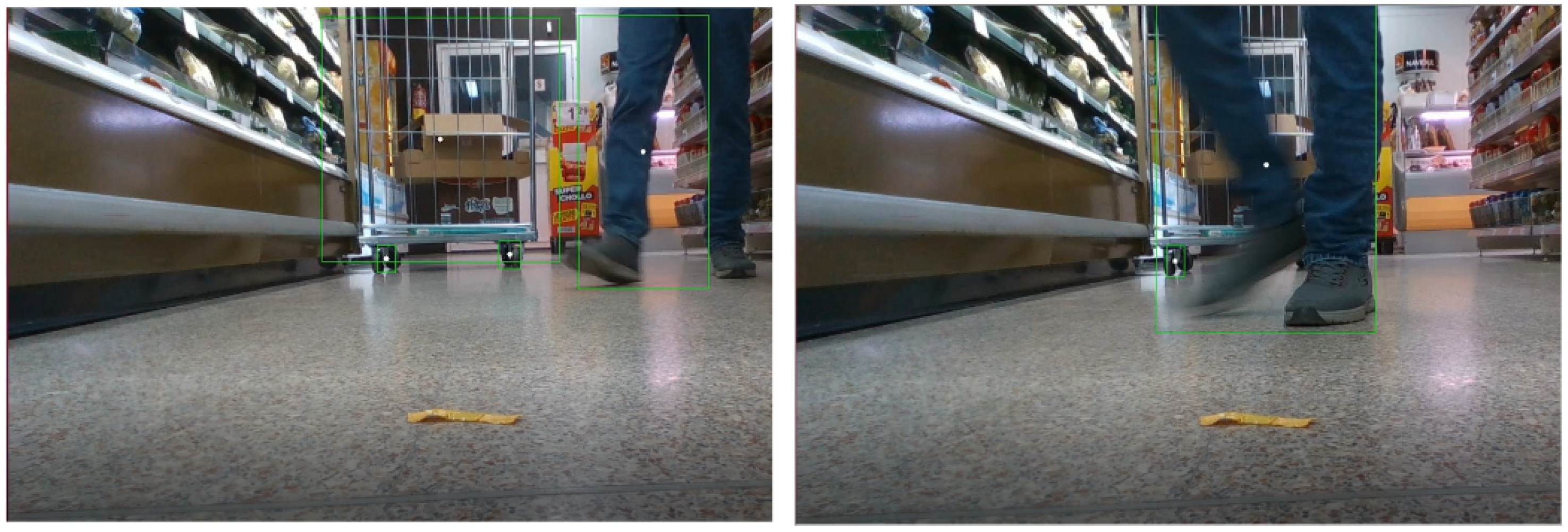
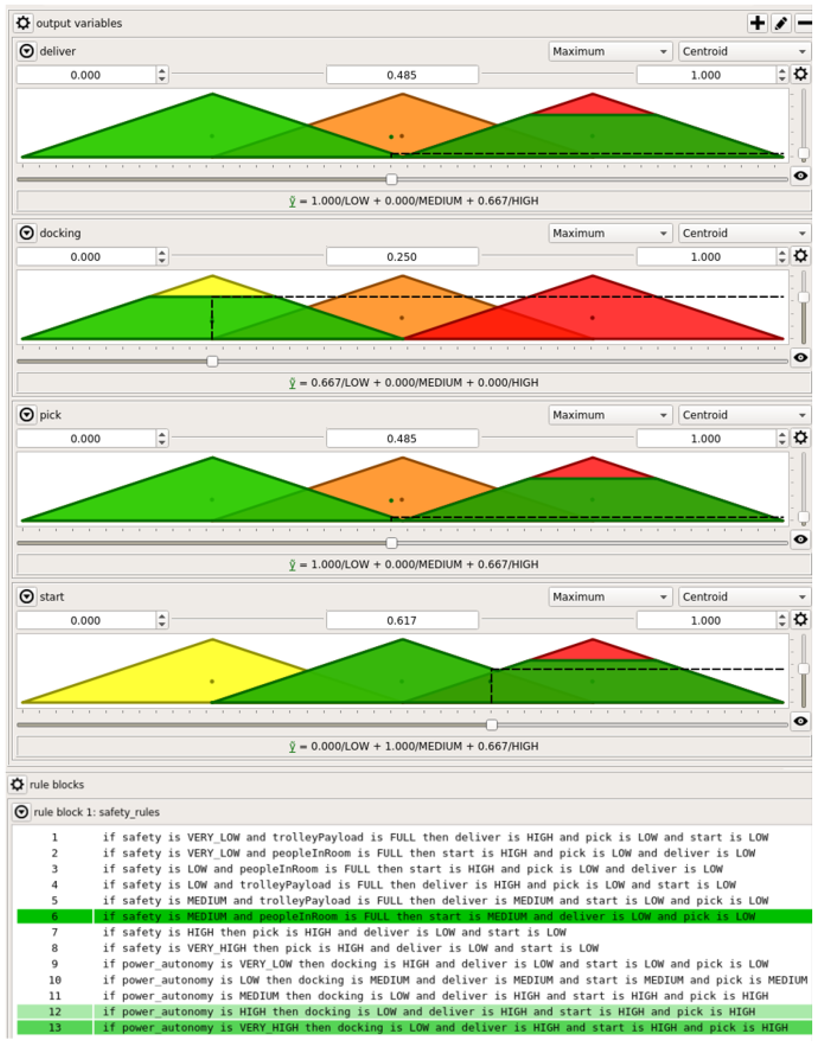
The robot can move the roll container through the corridors in the store despite the presence of people. However, for the picking up action, the robot needs to rotate, and it was considered that the presence of people made the situation unsafe. As was shown in Figure 3, the final result is to abort the pickingUp action. Figure 10 shows some snapshots of the detection of a person crossing in front of the roll container. In the FuzzyEngine, the context forces the safety metric to decrease, and the option start (aborting the mission and returning to the starting pose) to be the best valuated. As aforementioned, the FuzzyEngine includes two consecutive engines. In the first one, fuzzified context variables are employed for obtaining the QoS metrics. In the second one, context variables and QoS metrics are used for weighting the tentative actions encoded in the Global Management BT (pick, deliver, start, and dock). Figure 11 and Figure 12 show the outputs of both inference engines (QoS metrics and tentative actions) in this situation. The safety metric provides a low value (0.5) due to the presence of people close to the roll container (and although the container is empty). The start action gets greater values than the other possible actions.
Finally, we describe the evolution of the DSR when the robot arrives to a picking area, but it is not able to detect the roll container from the observation pose #1. Figure 13 shows how the PickingBehaviourTreeAgent manages the situation, using the DSR for allowing the BehaviourTreeAgent to be aware of the problem. The example shows that all agents interact to unfold the correct behaviour by maintaining a inner dialogue in the DSR.

7. Conclusions and Future Work

The existence of a knowledge representation is a crucial item of most robotic applications. In this contribution, we describe the use of the Deep State Representation (DSR) for assuming this role in a framework where several MAPE-K loops coexist managing the robot’s behaviour. This short-term memory is able to organize the information coming from a collection of software agents. The internalized entities can have geometric significance or be symbolic items. And they can be related by semantically or geometrically annotated links. All the representation is updated in runtime. Moreover, the semantic representation of the state, including perceptive items and also action-related ones, allows the robot to interpret the DSR as a source for inner dialogue [30]. This dialogue is used by the agents in the architecture for coordinating their activities. The deliberative decision making modules can determine what the action being executed is and modifying their behaviour. And the reactive modules can also quickly react to changes in the context and, updating the DSR, can also modulate the behaviour of the deliberative modules.
The proposal has been successfully instantiated in the intralogistic domain. In this example, two BT Executors are employed for providing the deliberative behaviour. Their outcomes are synchronized by considering the information annotated in the DSR. Moreover, the DSR also maintains the weights that the whole framework associate to the collection of actions that the robot can address. This allows the system to change the course of action according to the changes in the external and internal context. The approach has been successfully tested in a real environment.
Future work should focus on extending the evaluation in this domain and consider a global manager that can deal with a fleet of robots. Decisions at fleet- and robot-level must then be synchronized. A global DSR should integrate information coming from the local representations endowed in the robots of the fleet.

Author Contributions

Conceptualization, A.H.-P.; Funding acquisition, M.G.-G. and A.B.; Investigation, A.R.-G., A.H.-P. and A.B.; Methodology, A.R.-G.; Software, A.R.-G.; Supervision, A.B.; Validation, A.R.-G., M.G.-G. and A.B.; Writing—original draft, A.R.-G. and A.B.; Writing—review & editing, A.R.-G., A.H.-P., M.G.-G. and A.B. All authors have read and agreed to the published version of the manuscript.

Funding

This work has been partially developed within SA3IR (an experiment funded by EU H2020 ESMERA Project under Grant Agreement 780265), the project RTI2018-099522-B-C4X, funded by the Gobierno de España and FEDER funds, and the B1-2021_26 project, funded by the University of Málaga.

Acknowledgments

Special thanks to Isidro, manager of the Eroski in Casarabonela, and to all the employees for their kindness and availability.

Conflicts of Interest

The authors declare no conflict of interest.

References

  1. Kephart, J.; Chess, D. The vision of autonomic computing. Computer 2003, 36, 41–50. [Google Scholar] [CrossRef]
  2. Aehnelt, M.; Urban, B. The Knowledge Gap: Providing Situation-Aware Information Assistance on the Shop Floor. In Proceedings of the HCI in Business; Fui-Hoon Nah, F., Tan, C.H., Eds.; Springer International Publishing: Cham, Switzerland, 2015; pp. 232–243. [Google Scholar]
  3. Vromant, P.; Weyns, D.; Malek, S.; Andersson, J. On interacting control loops in self-adaptive systems. In Proceedings of the 6th International Symposium on Software Engineering for Adaptive and Self-Managing Systems, Honolulu, HI, USA, 23–24 May 2011; pp. 202–207. [Google Scholar] [CrossRef]
  4. Giese, H.; Bencomo, N.; Pasquale, L.; Ramirez, A.J.; Inverardi, P.; Wätzoldt, S.; Clarke, S. Living with Uncertainty in the Age of Runtime Models. In [email protected]: Foundations, Applications, and Roadmaps; Bencomo, N., France, R., Cheng, B.H.C., Aßmann, U., Eds.; Springer International Publishing: Cham, Switzerland, 2014; pp. 47–100. [Google Scholar] [CrossRef]
  5. Bustos, P.; Manso, L.; Bandera, A.; Bandera, J.; García-Varea, I.; Martínez-Gómez, J. The CORTEX cognitive robotics architecture: Use cases. Cogn. Syst. Res. 2019, 55, 107–123. [Google Scholar] [CrossRef]
  6. Marfil, R.; Romero-Garces, A.; Bandera, J.; Manso, L.; Calderita, L.; Bustos, P.; Bandera, A.; Garcia-Polo, J.; Fernandez, F.; Voilmy, D. Perceptions or Actions? Grounding How Agents Interact Within a Software Architecture for Cognitive Robotics. Cogn. Comput. 2020, 12, 479–497. [Google Scholar] [CrossRef]
  7. Paulius, D.; Sun, Y. A Survey of Knowledge Representation in Service Robotics. Robot. Auton. Syst. 2019, 118, 13–30. [Google Scholar] [CrossRef]
  8. Hochgeschwender, N.; Schneider, S.; Voos, H.; Bruyninckx, H.; Kraetzschmar, G.K. Graph-based software knowledge: Storage and semantic querying of domain models for run-time adaptation. In Proceedings of the 2016 IEEE International Conference on Simulation, Modeling, and Programming for Autonomous Robots (SIMPAR), San Francisco, CA, USA, 13–16 December 2016; pp. 83–90. [Google Scholar] [CrossRef]
  9. Dang, H.; Allen, P.K. Semantic grasping: Planning task-specific stable robotic grasps. Auton. Robot. 2014, 37, 301–316. [Google Scholar] [CrossRef]
  10. Galindo, C.; Fernández-Madrigal, J.A.; González, J.; Saffiotti, A. Robot task planning using semantic maps. Robot. Auton. Syst. 2008, 56, 955–966. [Google Scholar] [CrossRef]
  11. Pangercic, D.; Pitzer, B.; Tenorth, M.; Beetz, M. Semantic Object Maps for robotic housework - representation, acquisition and use. In Proceedings of the 2012 IEEE/RSJ International Conference on Intelligent Robots and Systems, Vilamoura-Algarve, Portugal, 7–12 October 2012; pp. 4644–4651. [Google Scholar] [CrossRef] [Green Version]
  12. Singh Chaplot, D.; Salakhutdinov, R.; Gupta, A.; Gupta, S. Neural Topological SLAM for Visual Navigation. In Proceedings of the 2020 IEEE/CVF Conference on Computer Vision and Pattern Recognition (CVPR), Seattle, WA, USA, 13–19 June 2020; pp. 12872–12881. [Google Scholar] [CrossRef]
  13. Chen, C.; Majumder, S.; Al-Halah, Z.; Gao, R.; Ramakrishnan, S.K.; Grauman, K. Audio-Visual Waypoints for Navigation. arXiv 2020, arXiv:2008.09622. [Google Scholar]
  14. Liao, Z.; Zhang, Y.; Luo, J.; Yuan, W. TSM: Topological Scene Map for Representation in Indoor Environment Understanding. IEEE Access 2020, 8, 185870–185884. [Google Scholar] [CrossRef]
  15. Armeni, I.; He, Z.Y.; Zamir, A.; Gwak, J.; Malik, J.; Fischer, M.; Savarese, S. 3D Scene Graph: A Structure for Unified Semantics, 3D Space, and Camera. In Proceedings of the 2019 IEEE/CVF International Conference on Computer Vision (ICCV), Seoul, Korea, 27 October–2 November 2019; pp. 5663–5672. [Google Scholar] [CrossRef]
  16. Rosinol, A.; Violette, A.; Abate, M.; Hughes, N.; Chang, Y.; Shi, J.; Gupta, A.; Carlone, L. Kimera: From SLAM to spatial perception with 3D dynamic scene graphs. Int. J. Robot. Res. 2021, 40, 1510–1546. [Google Scholar] [CrossRef]
  17. Wu, S.C.; Wald, J.; Tateno, K.; Navab, N.; Tombari, F. SceneGraphFusion: Incremental 3D Scene Graph Prediction from RGB-D Sequences. In Proceedings of the 2021 IEEE/CVF Conference on Computer Vision and Pattern Recognition (CVPR), Nashville, TN, USA, 2 November 2021; pp. 7511–7521. [Google Scholar] [CrossRef]
  18. Hughes, N.; Chang, Y.; Carlone, L. Hydra: A Real-time Spatial Perception System for 3D Scene Graph Construction and Optimization. arXiv 2022, arXiv:2201.13360. [Google Scholar] [CrossRef]
  19. Bavle, H.; Sanchez-Lopez, J.L.; Shaheer, M.; Civera, J.; Voos, H. Situational Graphs for Robot Navigation in Structured Indoor Environments. arXiv 2022, arXiv:2202.12197. [Google Scholar] [CrossRef]
  20. Sousa, Y.C.N.; Bassani, H.F. Topological Semantic Mapping by Consolidation of Deep Visual Features. IEEE Robot. Autom. Lett. 2022, 7, 4110–4117. [Google Scholar] [CrossRef]
  21. Tsai, C.; Su, M. VSGM - Enhance robot task understanding ability through visual semantic graph. arXiv 2021, arXiv:2105.08959. [Google Scholar]
  22. Rangel, J.C.; Cazorla, M.; García-Varea, I.; Romero-González, C.; Martínez-Gómez, J. Automatic semantic maps generation from lexical annotations. Auton. Robot. 2019, 43, 697–712. [Google Scholar] [CrossRef]
  23. Bernuy, F.; Ruiz-del-Solar, J. Topological Semantic Mapping and Localization in Urban Road Scenarios. J. Intell. Robot. Syst. 2018, 92, 19–32. [Google Scholar] [CrossRef]
  24. Roddick, T.; Cipolla, R. Predicting Semantic Map Representations From Images Using Pyramid Occupancy Networks. In Proceedings of the 2020 IEEE/CVF Conference on Computer Vision and Pattern Recognition (CVPR), Seattle, WA, USA, 13–19 June 2020; pp. 11135–11144. [Google Scholar] [CrossRef]
  25. Vogel, T.; Seibel, A.; Giese, H. The Role of Models and Megamodels at Runtime. In Models in Software Engineering—Proceedings of Workshops and Symposia at MODELS 2010, Oslo, Norway, 2–8 October 2010, Reports and Revised Selected Papers; Dingel, J., Solberg, A., Eds.; Lecture Notes in Computer Science; Springer: Berlin/Heidelberg, Germany, 2010; Volume 6627, pp. 224–238. [Google Scholar] [CrossRef]
  26. Romero-Garcés, A.; Freitas, R.S.D.; Marfil, R.; Vicente-Chicote, C.; Martínez, J.; Inglés-Romero, J.F.; Bandera, A. QoS metrics-in-the-loop for endowing runtime self-adaptation to robotic software architectures. Multim. Tools Appl. 2022, 81, 3603–3628. [Google Scholar] [CrossRef]
  27. Rada-Vilela, J. The FuzzyLite Libraries for Fuzzy Logic Control 2018. Available online: https://fuzzylite.com/ (accessed on 23 August 2022).
  28. Faconti, D. BehaviorTree.CPP. Available online: https://github.com/BehaviorTree/BehaviorTree.CPP (accessed on 23 August 2022).
  29. MIRA—Middleware for Robotic Applications. Available online: http://www.mira-project.org/joomla-mira/ (accessed on 23 August 2022).
  30. Chella, A.; Pipitone, A.; Morin, A.; Racy, F. Developing Self-Awareness in Robots via Inner Speech. Front. Robot. AI 2020, 7. [Google Scholar] [CrossRef] [PubMed] [Green Version]
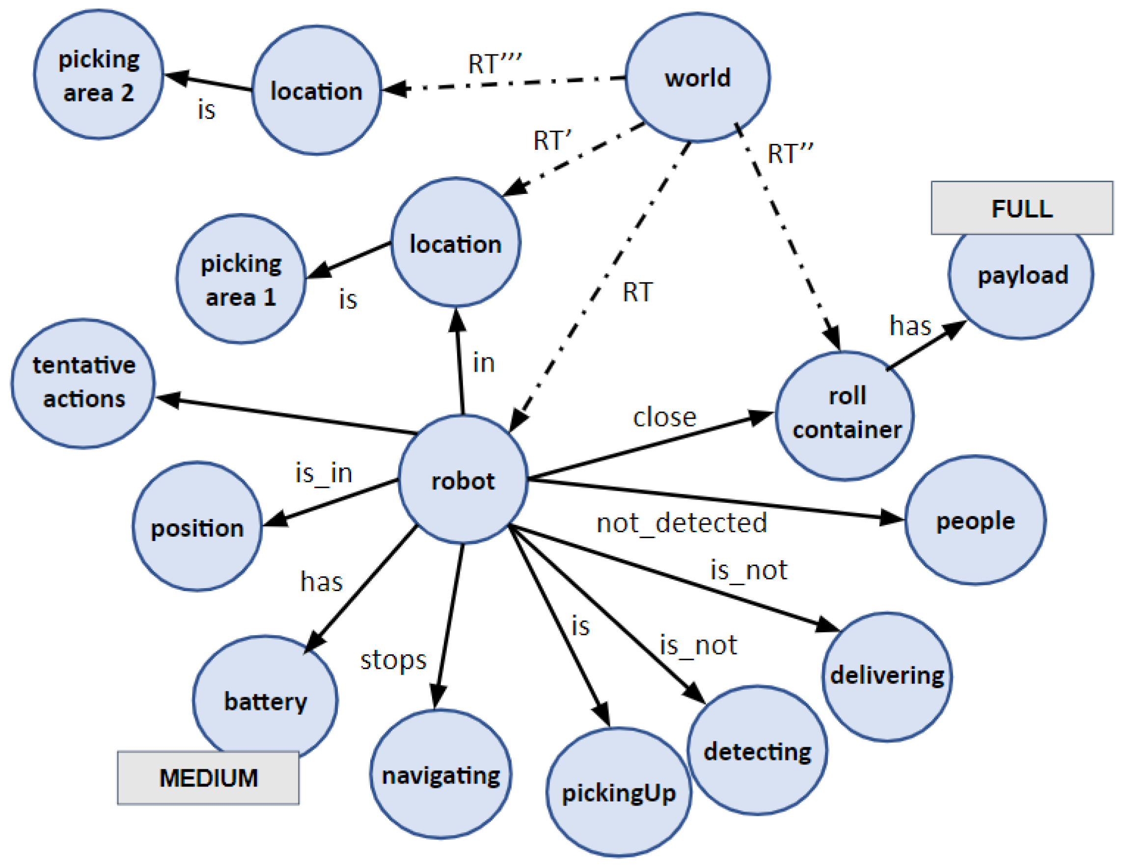
Figure 1. Unified representation as a multi-labelled directed graph. For instance, edges labelled as close or is_not denote logic predicates between nodes. On the other hand, edges starting at world and ending at robot and roll container are geometric and they encode a rigid transformation ( R T and R T respectively) between them. Geometric transformations can be chained or inverted to compute changes in coordinate systems (see text).
Applsci 12 08583 g001
Figure 2. Evolution of the DSR for starting a picking up task. The robot at time t has just reaching the picking area 1 and the decision maker finishes navigating and starts the detection of the roll container. Different agents interact using the information stored in the DSR for launching and stopping their activities. The DSR at time t + 5 includes the roll container and shows that the robot starts navigating for approaching to the container (see text). In the graphs, dark blue and bold text are used to highlight changes from one step to the next.
Applsci 12 08583 g002
Figure 3. Modification of the nominal course of action: the detection of people close to the robot causes the robot to abort the pickingUp task (see text).
Applsci 12 08583 g003
Figure 4. The proposed MAPE-K framework.
Applsci 12 08583 g004
Figure 5. The CARY robot approaches to a roll container, picks it up, and moves the container towards a new destination.
Applsci 12 08583 g005
Figure 6. Software architecture for managing the CARY robot.
Applsci 12 08583 g006
Figure 7. The main root of the Global Management BT. The nominal branch is the PickDeliverStart one. This branch commands the robot to pick up a roll container and move it to a delivery position within a certain picking area. Then, it returns to the Starting position. The alternative branches force the robot to (1) move the roll container directly to the Delivery position; (2) move the robot to the Starting position; or (3) move the robot to the Charging station.
Applsci 12 08583 g007
Figure 8. Key poses set in two picking areas in the store.
Applsci 12 08583 g008
Figure 9. Modification of the nominal course of action: the roll container is FULL and the robot aborts the delivering of this container to a second picking area for continuing its load (see text).
Applsci 12 08583 g009
Figure 10. The system detects the presence of a person walking close to the roll container. Images show that the system detects people and roll containers, but also the wheels of the roll container. Wheels are used for determining the pose of the container.
Applsci 12 08583 g010
Figure 11. QoS metrics provided by the FuzzyEngine when a person is detected close to the roll container (see text).
Applsci 12 08583 g011
Figure 12. Tentative actions provided by the FuzzyEngine when a person is detected close to the roll container (see text).
Applsci 12 08583 g012
Figure 13. Modification of the nominal course of action: The robot arrives to a picking area but it does not detect the roll container from the observation pose #1 and then navigates to the observation pose #2 to relaunch the search.
Applsci 12 08583 g013
Publisher’s Note: MDPI stays neutral with regard to jurisdictional claims in published maps and institutional affiliations.