
Numerical Analysis of Instability Mechanism of a High Slope under Excavation Unloading and Rainfall

Abstract
:1. Introduction
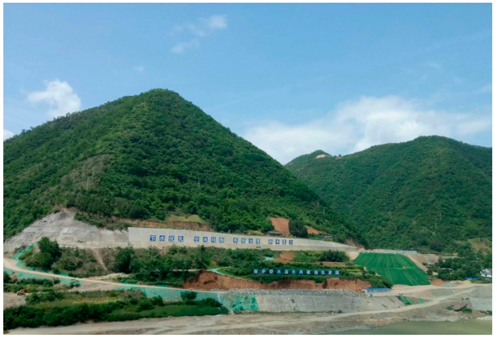
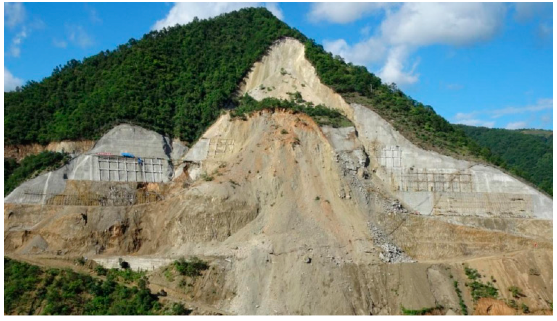
2. Project Overview
3. Impact of Rainfall on Slope Stability
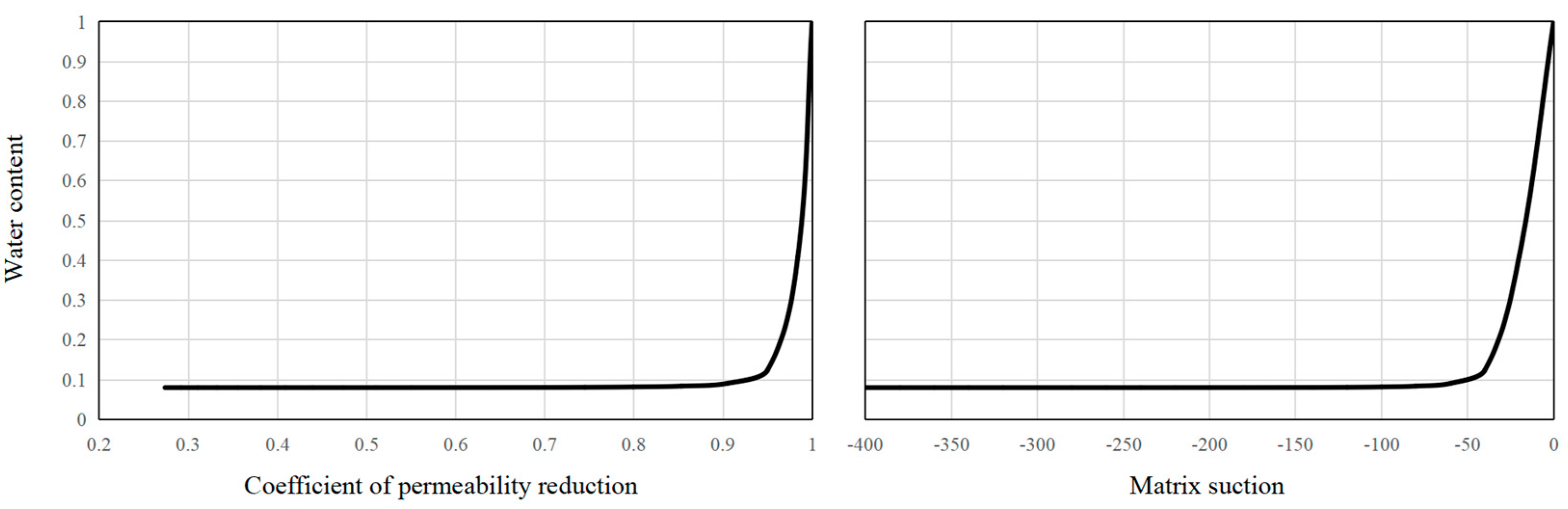
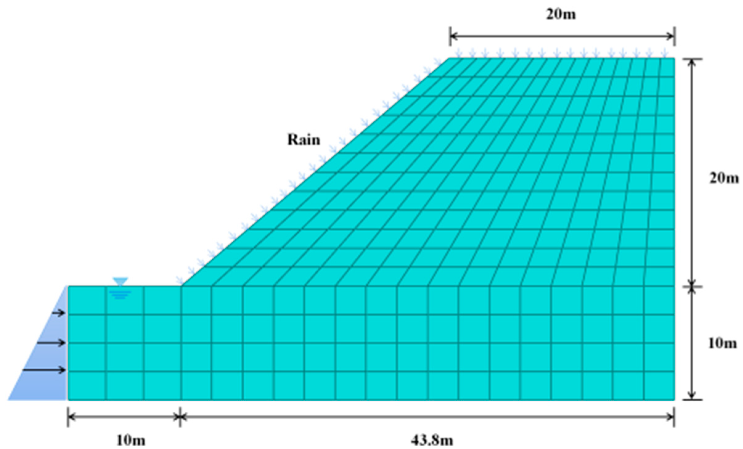
3.1. Numerical Simulation Model and Parameters
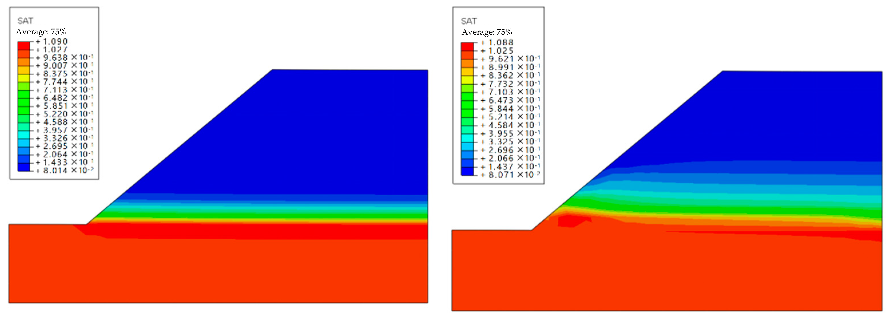
3.2. Analysis of Calculation Results
- (1)
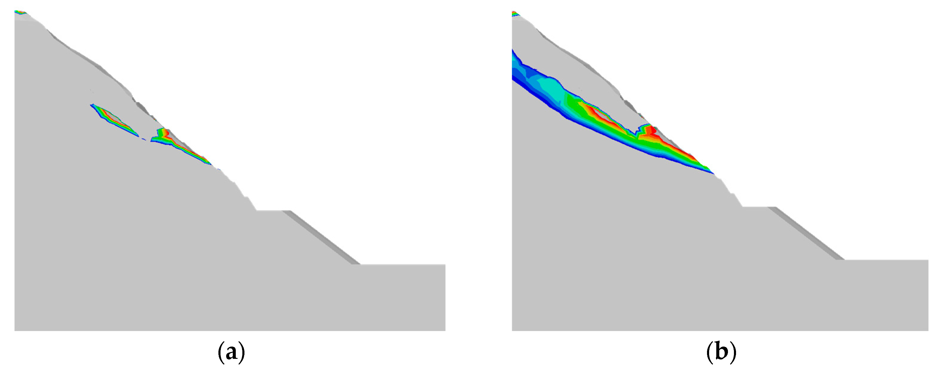
- Considering that the pore water pressure distribution after rainfall infiltration differs from the initial state, the suction area below the top of the slope decreases, and the matrix suction also decreases. Comparing the results at different times, it can be found that with the extension of rainfall time, the saturation increases, the pore water pressure increases, and the matrix suction in shallow soil decreases or disappears. After rainfall decreases or stops, saturation decreases gradually with the extension of time, saturation decreases, pore water pressure drops, and matrix suction in the shallow soil layer increases slowly.
- (2)
- The maximum horizontal displacement occurs at the slope toe, and the full settlement occurs in the middle of the soil slope. This is because, after rainfall infiltration, suction decreases. The pore pressure increases, the effective stress decreases, and the unloading rebound phenomenon occurs. On the other hand, with rainfall infiltration, soil moisture content and unit weight will increase, leading to heave and stress development. The slope tends to cause sliding deformation due to rainfall infiltration, so it can be considered that slope stability is reduced.
- (3)
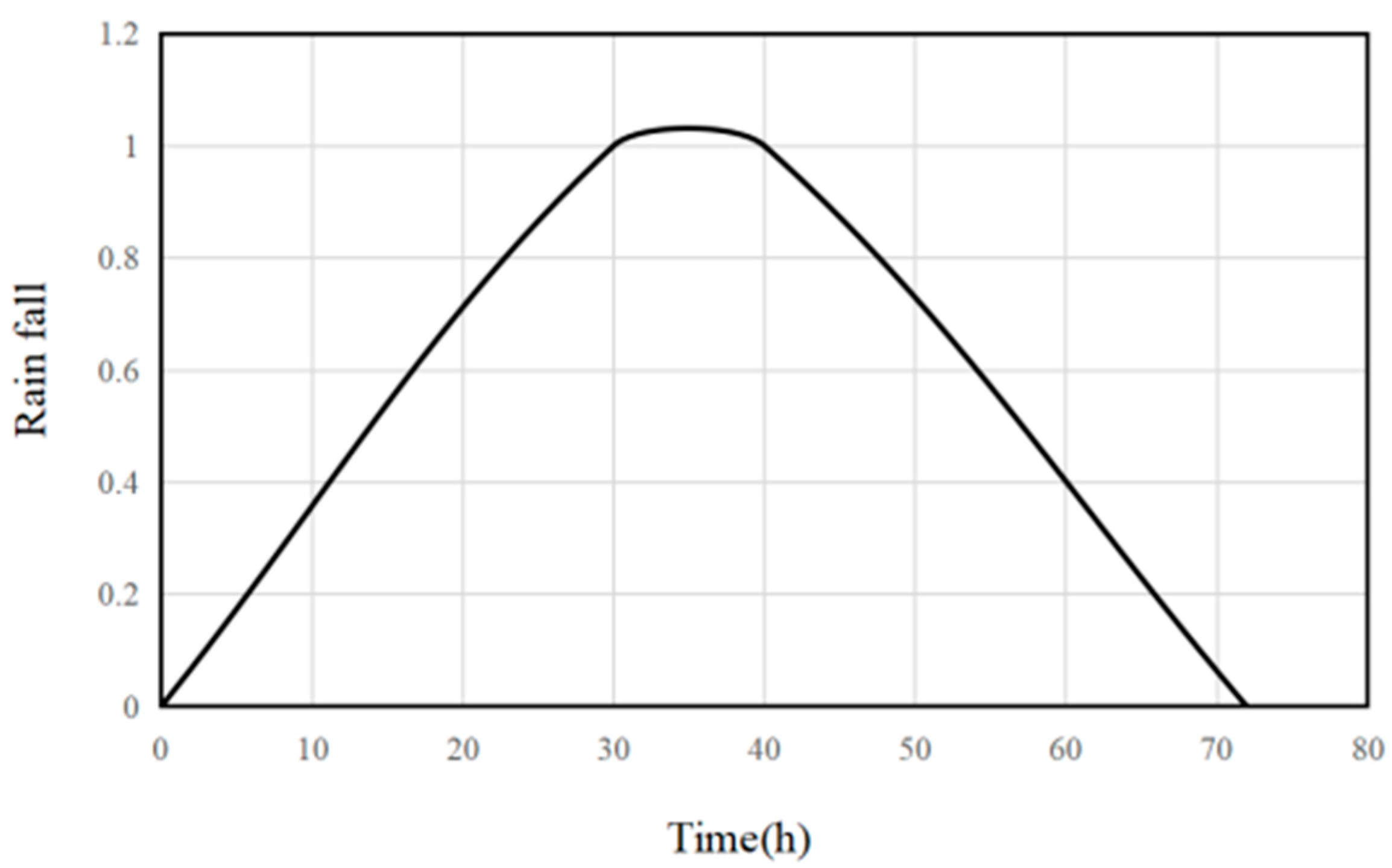
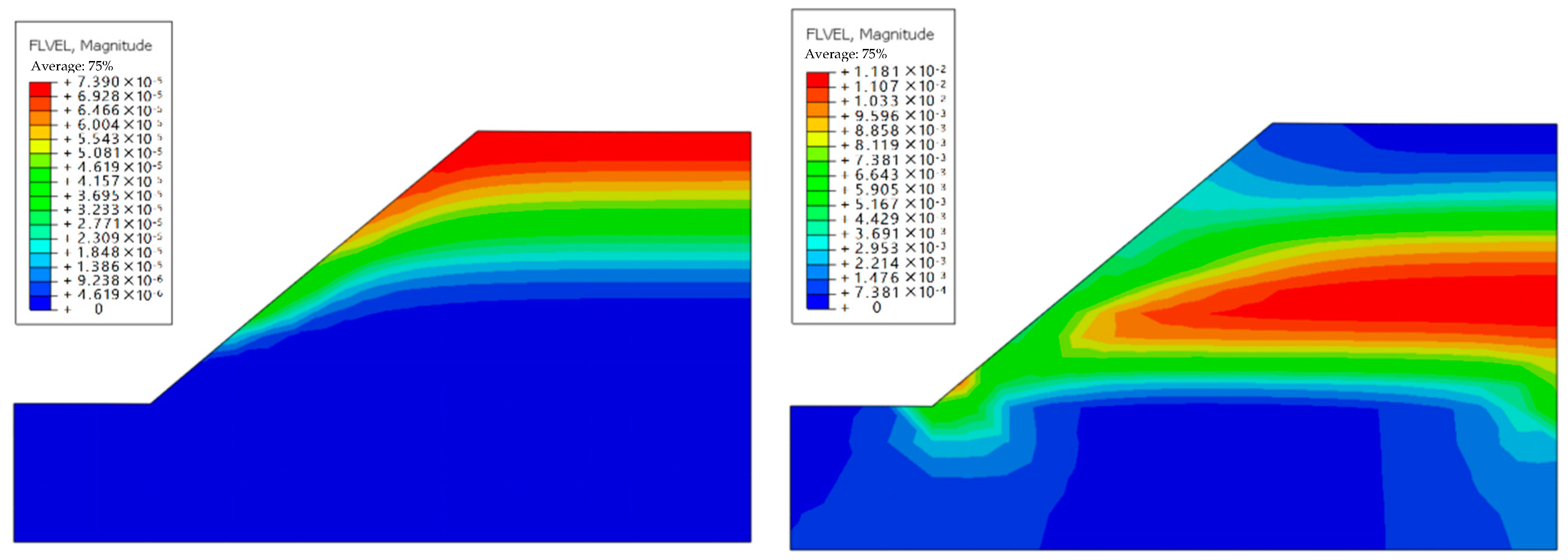
- As the rainfall intensity changes according to the law in Figure 2, it first increases from 0 to the maximum value and then gradually decreases to 0. Therefore, at the beginning of rainfall, rainwater infiltrates downward through the slope and slope top. As the rainfall intensity gradually decreases to 0, the overflow phenomenon occurs at the slope toe, and the flow velocity is largest at the middle elevation inside the slope.
- (4)
- For the slope toe element, the pore water pressure increases, and the effective average stress decreases under the action of rainfall infiltration. The effective stress path reaches the yield surface when it drops to a certain extent. Currently, the stress path moves to the left and down along the yield surface (Mohr–Coulomb strength envelope) until the rainfall gradually decreases, the suction increases, the pore water pressure drops, and the effective stress increases gradually shifts to the yield surface. For the internal unit of the soil slope, the unit weight above the unit increases after water absorption, increasing the average effective stress and partial stress. Until the later stage of rainfall, adequate moderate pressure and partial stress decrease near the end of the rains. This also confirms the view of some scholars that instability may occur mainly in the shallow layer of the slope under the action of rainfall infiltration [18,19].
4. Numerical Simulation Analysis of Slope Instability
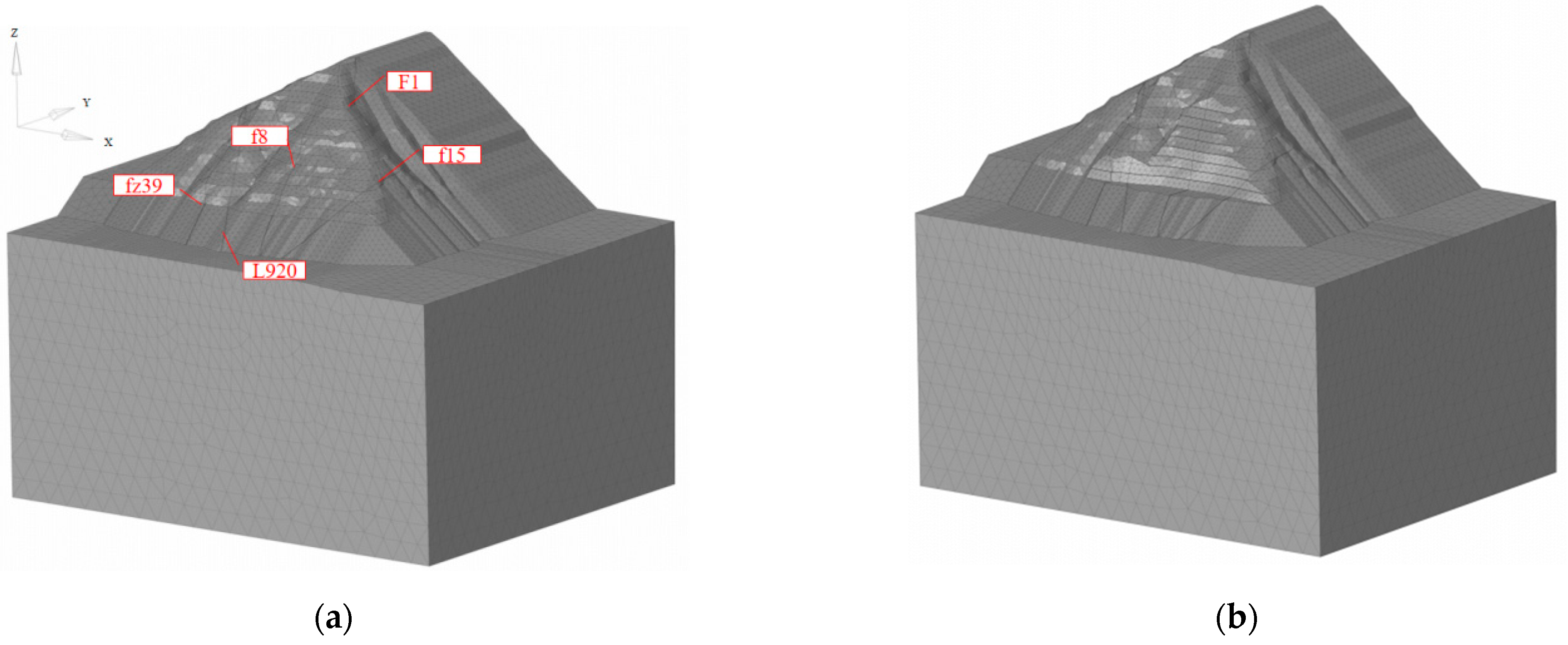
4.1. Finite Element Model
4.2. Slope Material Properties
4.3. Calculation Conditions and Boundary Conditions
4.4. Analysis of Finite Element Simulation Results
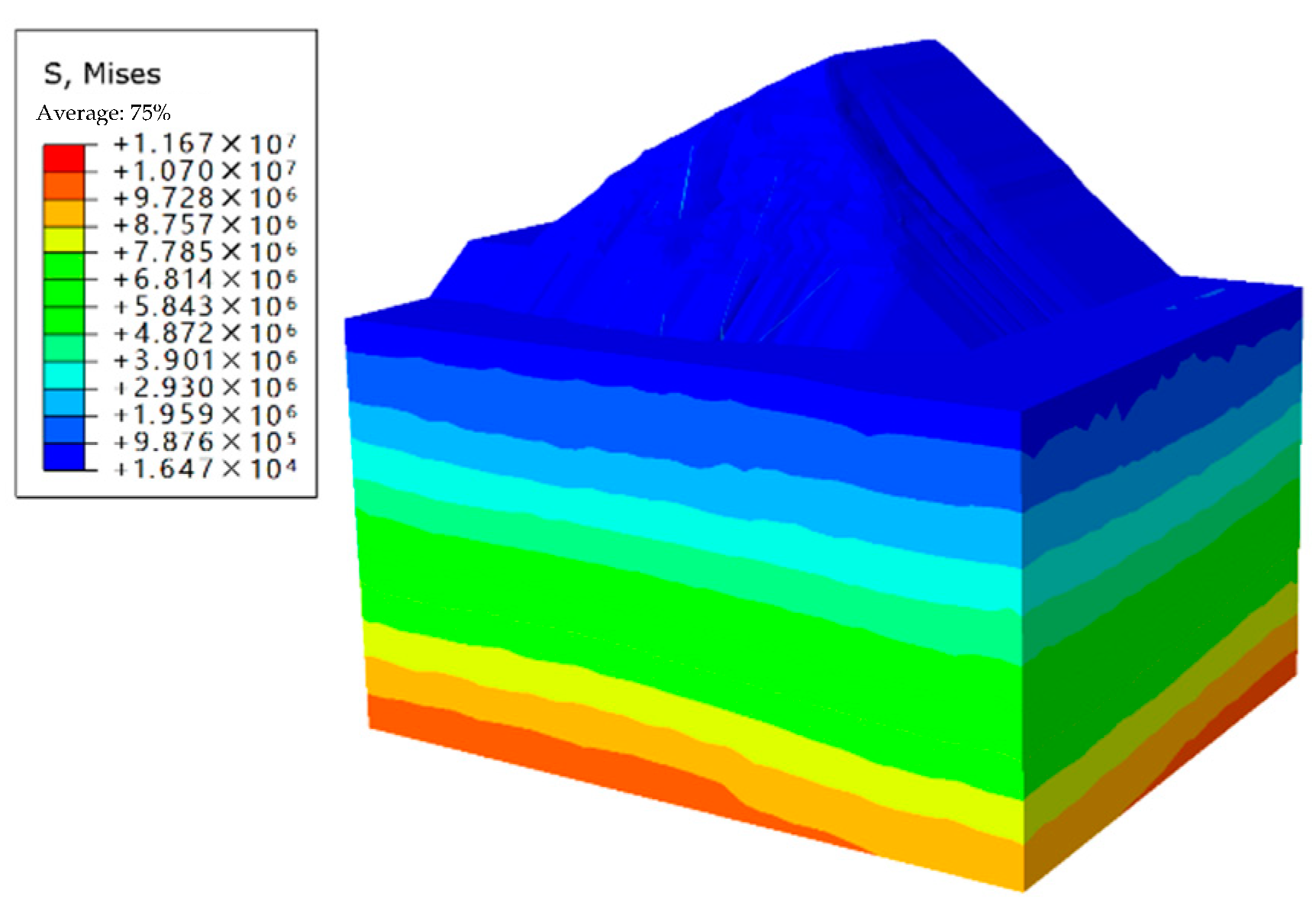
4.4.1. Initial Ground Stress
4.4.2. Slope Instability Analysis
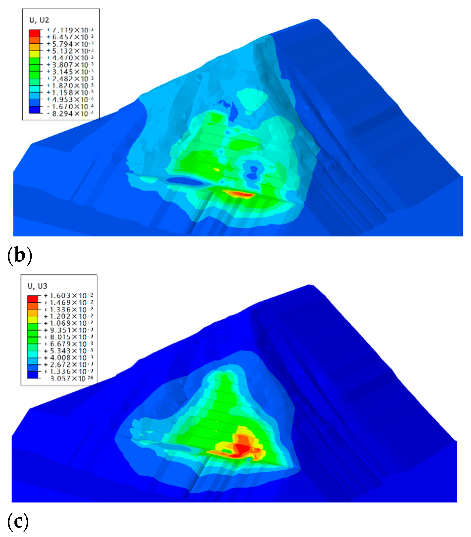
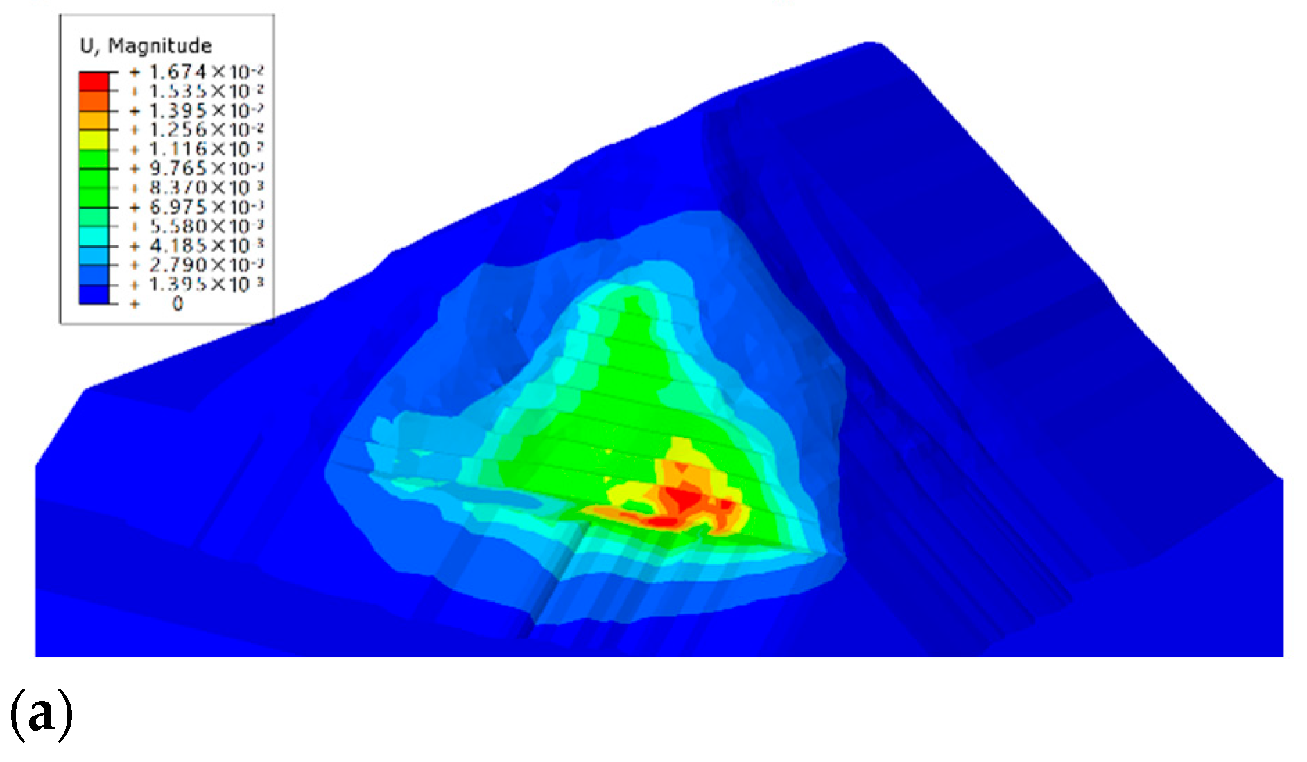
- (1)
- After the completion of the excavation, due to the influence of excavation unloading, the settlement and deformation of the left bank slope recover rapidly. Relative to the initial in situ stress state, the displacement is mainly vertical and upward, indicating that under excavation unloading, the left bank slope has rebounded in the excavation range and nearby soil. Due to the poor mechanical properties of the rock mass in the upper strongly weathered area, the slope in the strongly weathered area is mainly deformed along the slope direction, and the excavated slope in other parts is mainly deformed by unloading and rebounding toward the excavation free face. At the initial stage of excavation, the surface deformation of the slope mainly occurs downward, and the displacement of the slope before excavation is significantly greater than that after excavation. In the later stage of excavation, the whole body moves upward, and the displacement within the excavation range is significantly greater than that of the other parts.
- (2)
- When the excavation is completed, and the whole slope is balanced, the incremental deformation of the slope is between 3–160 mm, and the maximum value mainly occurs in the block with an elevation of 465–480 m and is surrounded by faults FZ8 and F15. The deformation of the front edge of the excavated slope is significant, and the rear rim is small.
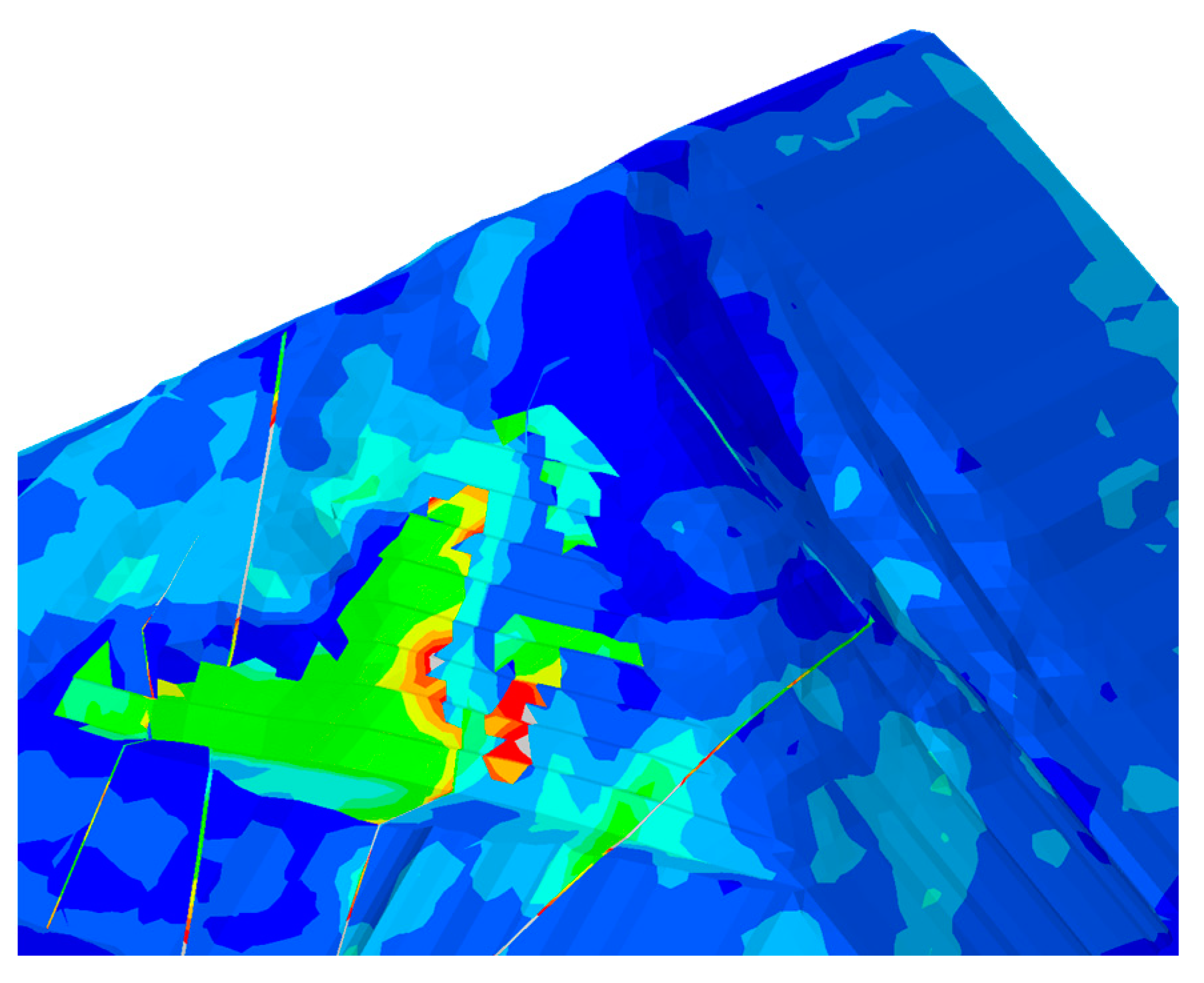
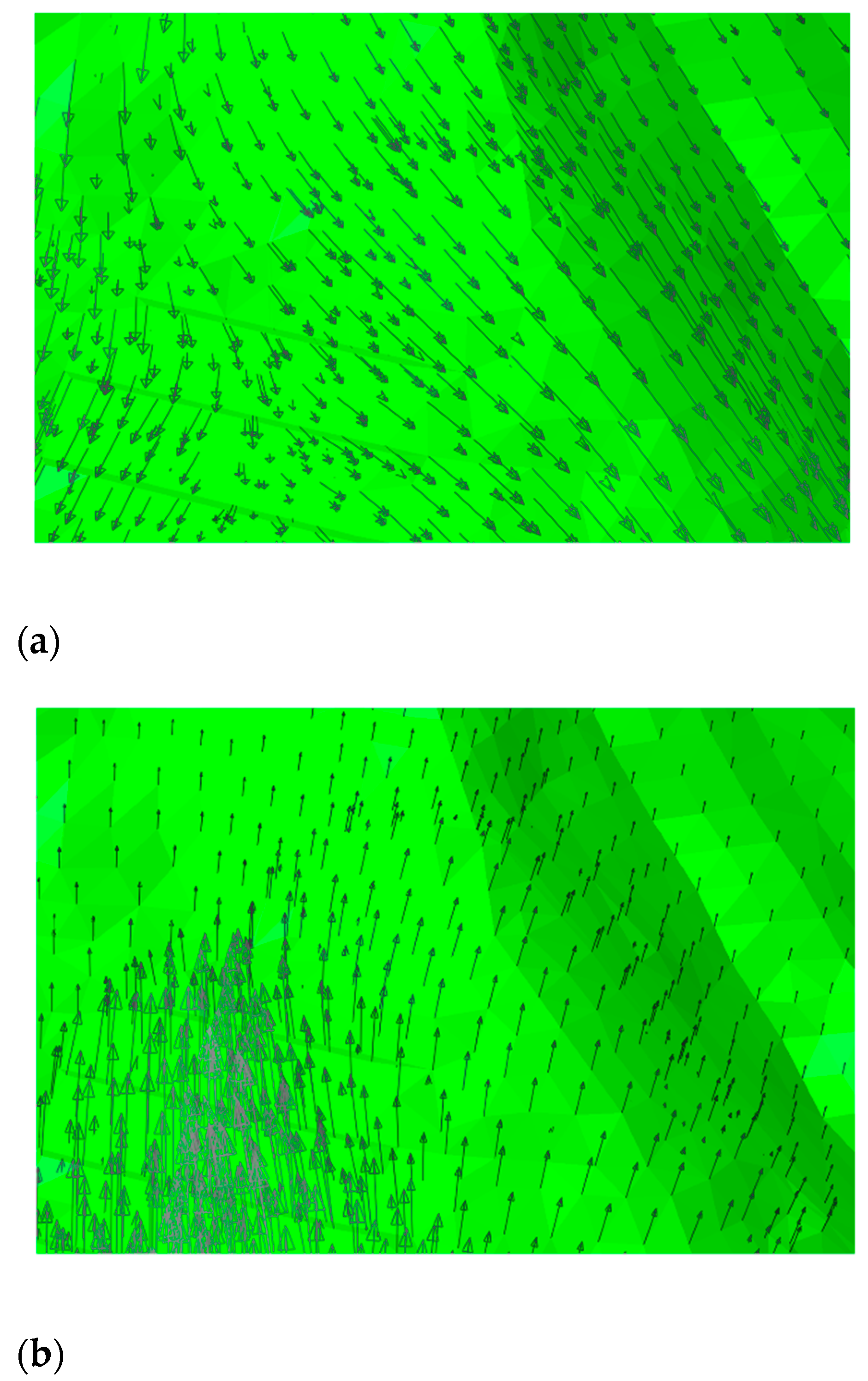
- (3)
- It is worth noting that in the displacement along the slope, there is a prominent area with large displacement at an elevation of about 615 m above the upper edge of the excavation. The displacement along the slope is about 1.5–2.5 times that of the excavation platform at an elevation of 590 m. This phenomenon may be caused by rebound deformation of the foundation soil due to excavation unloading. However, due to the existence of fault F1, the deformation is not coordinated, and the fault interior becomes loose. This may be one of the geological causes of the landslide on 19 July 2016.
4.4.3. Safety Factor of Slope Stability
5. Conclusions
- (1)
- With the extension of rainfall time, saturation increases, pore water pressure increases, and matrix suction in shallow soil decreases or disappears. After rainfall decreases or stops, saturation decreases gradually with the extension of time, pore water pressure drops, and matrix suction in the shallow soil layer increases slowly.
- (2)
- Under the action of excavation unloading, the high slope rebounds and deforms, resulting in a loose structural plane at fault F1 at the back edge of the excavated slope. Under the action of rainfall infiltration, saturation in the structural plane increases, and pore water pressure increases. With rainfall infiltration, the shear strain concentration area first appears at the inner structural plane of the slope. It extends along the structural plane to the front and rear edges of the slope, resulting in landslide failure of the slope.
- (3)
- For the typical structural plane-controlled slope, excavation unloading deformation is mainly represented by structural plane deformation. The slope deformation is composed chiefly of the structural plane dislocation deformation. Structural plane deformation is primarily controlled by the exposure of the structural plane when excavating the free face, excavation unloading scale, etc. The shear failure and unstable displacement caused by excavation unloading are the leading causes of landslides.
- (4)
- The unloading deformation of slope excavation is mainly manifested as the deformation of the structural plane, and the slope deformation is composed chiefly of the dislocation deformation of the structural plane. The deformation of the structural plane is mainly controlled by the exposure of the structural plane in excavating the free surface and the scale of excavation unloading. In practical applications, load-reduction measures can be used to improve the stability of the slope.
Author Contributions
Funding
Data Availability Statement
Conflicts of Interest
References
- Lee, B.X.; Kjaerulf, F.; Turner, S.; Cohen, L.; Donnelly, P.D.; Muggah, R.; Davis, R.; Realini, A.; Kieselbach, B.; MacGregor, L.S. Transforming our world: Implementing the 2030 agenda through sustainable development goal indicators. J. Public Health Policy 2016, 37, 13–31. [Google Scholar] [CrossRef]
- Torres-Suarez, M.C.; Alarcon-Guzman, A.; Moya, B.D. Effects of loadinge-unloading and wettinge-drying cycles on geomechanical behaviors of mudrocks in the Colombian Andes. J. Rock Mech. Geotech. Eng. 2014, 6, 257–268. [Google Scholar] [CrossRef] [Green Version]
- Zhang, J.; Kuang, M.; Zhang, Y.; Feng, T. Evaluation and analysis of the causes of a landslide and treatment measures during the excavation of a tunnel through a soil-rock interface. Eng. Fail. Anal. 2021, 130, 105784. [Google Scholar] [CrossRef]
- Zhu, T.; Huang, D. Experimental investigation of the shear mechanical behavior of sandstone under unloading normal stress. Int. J. Rock Mech. Min. Sci. 2019, 114, 186–194. [Google Scholar] [CrossRef]
- Xu, J.; Ueda, K.; Uzuoka, R. Numerical modeling of seepage and deformation of unsaturated slope subjected to post-earthquake rainfall. Comput. Geotech. 2022, 148, 104791. [Google Scholar] [CrossRef]
- Pan, Y.; Wu, G.; Zhao, Z.; He, L. Analysis of rock slope stability under rainfall conditions considering the water-induced weakening of rock. Comput. Geotech. 2020, 128, 103806. [Google Scholar] [CrossRef]
- Zhang, F.; Liu, G.; Chen, W.; Liang, S.; Chen, R.; Han, W. Human-induced landslide on a high cut slope: A case of repeated failures due to multi-excavation. J. Rock Mech. Geotech. Eng. 2012, 4, 367–374. [Google Scholar] [CrossRef]
- Wang, S.; Xu, W.; Yan, L.; Feng, X.-T.; Xie, W.-C.; Chen, H. Experimental investigation and failure mechanism analysis for dacite under true triaxial unloading conditions. Eng. Geol. 2019, 264, 105407. [Google Scholar] [CrossRef]
- Dai, J.; Yang, J.; Yao, C.; Hu, Y.; Zhang, X.; Jiang, Q.; Zhou, C. Study on the mechanism of displacement mutation for jointed rock slopes during blasting excavation. Int. J. Rock Mech. Min. Sci. 2022, 150, 105032. [Google Scholar] [CrossRef]
- Li, C.; Fu, Z.; Wang, Y.; Tang, H.; Yan, J.; Gong, W.; Yao, W.; Criss, R.E. Susceptibility of reservoir-induced landslides and strategies for increasing the slope stability in the Three Gorges Reservoir Area: Zigui Basin as an example. Eng. Geol. 2019, 261, 105279. [Google Scholar] [CrossRef]
- Wyllie, D.C.; Mah, C. Rock Slope Engineering; CRC Press: Boca Raton, FL, USA, 2004. [Google Scholar]
- Shen, J.H.; Wang, L.S.; Wang, Q.H.; Xu, J.; Jiang, Y.S.; Sun, B.J. Deformation and fracture features of unloading rock mass. Chin. J. Rock Mech. Eng. 2003, 22, 2028–2031. [Google Scholar]
- Ha, Q.L. Simulation analysis of rock mass engineering and rock mass mechanic. Chin. J. Geotech. Eng. 2001, 23, 664–668. [Google Scholar]
- Li, J.L.; Ha, Q.L. The three demensions numerical model of unloading rock mass mechanics parameters related to three-gorges. J. Univ. Hydr. Elec. Eng. 1997, 19, 1–6. [Google Scholar]
- Chen, C.; Xu, T.; Heap, M.J.; Baud, P. Influence of unloading and loading stress cycles on the creep behavior of Darley Dale Sandstone. Int. J. Rock Mech. Min. Sci. 2018, 112, 55–63. [Google Scholar] [CrossRef]
- Peng, J.; Fan, Z.; Wu, D.; Huang, Q.; Wang, Q.; Zhuang, J.; Che, W. Landslides triggered by excavation in the loess plateau of China: A case study of Middle Pleistocene loess slopes. J. Asian Earth Sci. 2019, 171, 246–258. [Google Scholar] [CrossRef]
- Zhang, Y.; Jiang, H.; Bai, G.; Han, B. Coupling Action of rainfall and vehicle loads impact on the stability of loess slopes based on the iso-water content layer. Earthq. Res. Adv. 2022, 2, 100143. [Google Scholar] [CrossRef]
- Li, Q.; Song, D.; Yuan, C.; Nie, W. An image recognition method for the deformation area of open-pit rock slopes under variable rainfall. Measurement 2022, 188, 110544. [Google Scholar] [CrossRef]
- Gao, Q.F.; Zeng, L.; Shi, Z.N. Effects of desiccation cracks and vegetation on the shallow stability of a red clay cut slope under rainfall infiltration. Comput. Geotech. 2021, 140, 104436. [Google Scholar] [CrossRef]
- Chang, Z.; Huang, F.; Huang, J.; Jiang, S.-H.; Zhou, C.; Zhu, L. Experimental study of the failure mode and mechanism of loess fill slopes induced by rainfall. Eng. Geol. 2021, 280, 105941. [Google Scholar] [CrossRef]
- Song, X.; Tan, Y. Experimental study on failure of temporary earthen slope triggered by intense rainfall. Eng. Fail. Anal. 2020, 116, 104718. [Google Scholar] [CrossRef]
- Cuomo, S.; Di Perna, A.; Martinelli, M. Modelling the spatio-temporal evolution of a rainfall-induced retrogressive landslide in an unsaturated slope. Eng. Geol. 2021, 294, 106371. [Google Scholar] [CrossRef]
- Zheng, H.; Shi, Z.; Shen, D.; Peng, M.; Hanley, K.J.; Ma, C.; Zhang, L. Recent advances in stability and failure mechanisms of landslide dams. Front. Earth Sci. 2021, 9, 659935. [Google Scholar] [CrossRef]
- Zhang, S.; Zhang, X.; Pei, X.; Wang, S.; Huang, R.; Xu, Q.; Wang, Z. Model test study on the hydrological mechanisms and early warning thresholds for loess fill slope failure induced by rainfall. Eng. Geol. 2019, 258, 105135. [Google Scholar] [CrossRef]
- Li, Q.; Wang, Y.M.; Zhang, K.B.; Yu, H.; Tao, Z.Y. Field investigation and numerical study of a siltstone slope instability induced by excavation and rainfall. Landslides 2020, 17, 1485–1499. [Google Scholar] [CrossRef]
- Yu, X.; Gong, B.; Tang, C. Study of the slope deformation characteristics and landslide mechanisms under alternating excavation and rainfall disturbance. Bull. Eng. Geol. Environ. 2021, 80, 7171–7191. [Google Scholar] [CrossRef]
- Xu, X.; Xing, Y.; Guo, Z.; Huang, Y. Stability analysis of rainfall-triggered toe-cut slopes and effectiveness evaluation of pile-anchor structures. J. Earth Sci. 2021, 32, 1104–1112. [Google Scholar] [CrossRef]
- Yadav, O.P.; Jiwari, R. A finite element approach for analysis and computational modelling of coupled reaction diffusion models. Numer. Methods Partial. Differ. Equ. 2019, 35, 830–850. [Google Scholar] [CrossRef]
- Yadav, O.P.; Jiwari, R. A finite element approach to capture Turing patterns of autocatalytic Brusselator model. J. Math. Chem. 2019, 57, 769–789. [Google Scholar] [CrossRef]
- Greco, R.; Comegna, L.; Damiano, E.; Marino, P.; Olivares, L.; Santonastaso, G.F. Recurrent rainfall-induced landslides on the slopes with pyroclastic cover of Partenio Mountains (Campania, Italy): Comparison of 1999 and 2019 events. Eng. Geol. 2021, 288, 106160. [Google Scholar] [CrossRef]
- Fang, Q.; Zhao, L.; Hou, R.; Fan, C.; Zhang, J. Rainwater transformation to runoff and soil loss at the surface and belowground on soil-mantled karst slopes under rainfall simulation experiments. CATENA 2022, 215, 106316. [Google Scholar] [CrossRef]
- Tang, G.; Huang, J.; Sheng, D.; Sloan, S.W. Stability analysis of unsaturated soil slopes under random rainfall patterns. Eng. Geol. 2018, 245, 322–332. [Google Scholar] [CrossRef]


| Rock Mass and Fault Zoning | Severe | Deformation Parameters | Strength Parameters | ||
|---|---|---|---|---|---|
| Intensely weathered | 26.5 | 0.5 | 0.32 | 24 | 0.15 |
| Weakly weathered upper layer | 28.2 | 4.5 | 0.27 | 40 | 0.8 |
| Weakly weathered lower layer | 28.4 | 6.5 | 0.26 | 45 | 0.9 |
| Micro new rock | 28.5 | 18.0 | 0.25 | 50 | 1.1 |
| f8 | 27.0 | 0.5 | 0.32 | 15 | 0.24 |
| F1 | 26.0 | 0.5 | 0.32 | 16 | 0.25 |
| f15 | 26.0 | 0.5 | 0.28 | 16 | 0.3 |
| f39-1/f39 | 26.0 | 0.5 | 0.32 | 16 | 0.22 |
| L920 | 27.0 | 3.5 | 0.26 | 23 | 0.75 |
| Model Type | Calculated Safety Factor | Tolerable Safety Factor | |
|---|---|---|---|
| Original model | 1.09 | 0.5 | 1.35 |
| First Excavation Model | 1.10 | 4.5 | 1.35 |
| Second Excavation Model | 1.27 | 3.5 | 1.35 |
Publisher’s Note: MDPI stays neutral with regard to jurisdictional claims in published maps and institutional affiliations. |
© 2022 by the authors. Licensee MDPI, Basel, Switzerland. This article is an open access article distributed under the terms and conditions of the Creative Commons Attribution (CC BY) license (https://creativecommons.org/licenses/by/4.0/).
Share and Cite
Qu, M.; Dang, F. Numerical Analysis of Instability Mechanism of a High Slope under Excavation Unloading and Rainfall. Appl. Sci. 2022, 12, 7990. https://doi.org/10.3390/app12167990
Qu M, Dang F. Numerical Analysis of Instability Mechanism of a High Slope under Excavation Unloading and Rainfall. Applied Sciences. 2022; 12(16):7990. https://doi.org/10.3390/app12167990
Chicago/Turabian StyleQu, Manli, and Faning Dang. 2022. "Numerical Analysis of Instability Mechanism of a High Slope under Excavation Unloading and Rainfall" Applied Sciences 12, no. 16: 7990. https://doi.org/10.3390/app12167990
APA StyleQu, M., & Dang, F. (2022). Numerical Analysis of Instability Mechanism of a High Slope under Excavation Unloading and Rainfall. Applied Sciences, 12(16), 7990. https://doi.org/10.3390/app12167990