1. Introduction
Water is a vital and scarce resource; there is a growing public concern about pollutants in water and their effective removal. Particularly, the presence of several molecules commonly known as contaminants of emerging concern (CEC) has drawn the scientific community’s attention. In fact, these contaminants are refractory to the conventional wastewater treatment plants (WWTP), which can pass through unchanged and reach the water sources. Examples of these pollutants can include pharmaceuticals (e.g., antimicrobials, analgesics and anti-inflammatory, β-blockers, and lipid regulators), synthetic hormones, flame retardants, and personal care products. Due to the inefficacy of conventional WWTP, the CECs have been found in water bodies in trace concentrations (a few ng/L to µg/L), and adverse human health effects may occur [
1,
2,
3]. Among the drugs of environmental concern occurring in aqueous media, sulfamethoxazole (SMX) has been widely reported. For example, in northern Vietnam, Hoa et al. [
4] found 0.6 to 4.3 µg/L of SMX in aquatic environments. Madureira et al. [
5] studied the spatial and temporal distribution of pharmaceuticals along the Douro River estuary (Portugal). The maximum concentration of SMX found was about 53.3 ng/L.
The impact of SMX on the environment is related to the ability to provide antimicrobial resistance in both commensal bacteria from the human and animal intestines, as well as environmental bacteria, through the spread of resistance genes among diverse bacterial populations [
6]. The occurrence of pharmaceuticals in water sources has been recognized as one of the emerging issues in environmental chemistry [
7]. This fact, associated with a lack of knowledge about other potential negative effects on global public health, justifies the need to establish legislation and improve wastewater treatment techniques.
Despite the advances and promising results in the removal process of recalcitrant compounds from aqueous media, through the application of advanced oxidation processes (AOP), there is still a long way to go to optimize processes for the industrial scale for treated water reuse. Photocatalysis presents advantages for this purpose, where the selection of the semiconductor is a key issue. In general, the adsorption of pollutants, light absorption, mass transfer, and charge separation are considered important factors for the photocatalytic activity of semiconductors [
8,
9]. The photocatalysis process converts light energy into chemical energy, promoting the appearance of holes (h+) at the valence band of semiconductors. These holes boost the production of hydroxyl radicals (▪OH) to promote non-selective photodegradation of CEC [
10,
11,
12].
Titanium dioxide (TiO
2) has been identified as the most suitable semiconductor for water treatment due to its chemical stability, corrosion resistance, non-toxicity, and low cost [
13,
14]. In this context, it is important to emphasize that the commercial photocatalyst, commonly named TiO
2 P25, presents high photocatalytic performance due to the optimal combination of anatase and rutile phases, the low bandgap energy, the specific surface area, and the small size of particles [
15,
16].
TiO
2 P25 is commonly used as a fine powder with a particle size of less than 100 nm. Thus, after effluent treatment, sophisticated separation methods are required, such as microfiltration, nanofiltration, and centrifugation for its recovery, which increases the complexity of the process and costs [
17,
18]. Given the difficulties inherent in its separation from reactional medium and maintaining its performance in photocatalytic processes, it is important to develop techniques for incorporating powders into supports. In this ambit, supports with high porosity, low density, and good mechanical resistance may have advantages in the absorption of light and catalyst immobilization [
14,
19,
20]. Specific ceramic materials have shown promising characteristics in this sense, namely when they reveal high adsorption capacity, large pore volume, thermal stability, and good mechanical properties [
21,
22]. In particular, the lightweight expanded clay aggregates (Leca
®) present good characteristics to support fine particulate catalysts. Leca is a ceramic material produced by firing clay in high-temperature rotary kilns. It is recognized as a substrate of great interest due to its inherent mechanical strength, low density, and high porosity [
23]. These characteristics may improve the mass transfer of the pollutant molecules through the catalyst and the absorption of light radiation [
24]. Leca has been used in lightweight mortars and concretes, refractory mortars, piping protection, prefabrication of structures, agriculture, and floriculture. Therefore, Leca presents good characteristics to be used as a support of TiO
2 in the photocatalytic oxidation processes.
Although few studies have considered Leca coating with TiO
2, it has already been identified as a good material for the degradation of several contaminants [
25,
26,
27]. Zendehzaban et al. [
25] demonstrated that TiO
2 nanoparticles supported on Leca achieved high levels of ammonia removal in liquid effluents through photocatalysis. Sohrabi and Akhlaghian [
26] showed that Cu/TiO
2/Leca reached good phenol degradation in synthetic wastewater. Some authors highlighted the advantage of TiO
2 coating of Leca due to its good adsorption properties, which promote photocatalytic activity [
27]. Długosz et al. [
28] coated TiO
2 on perlite light aggregates for water purification, confirming that the floating properties of these materials combined with TiO
2 can promote the use of sunlight in the purification of shallow water reservoirs and industrial waste stabilization ponds. Długosz et al. [
29] developed a TiO
2 photocatalyst supported by perlite light aggregates for degradation of SMX in aqueous solutions and verified improvements in the photodegradation rate, achieving 60% of degradation.
In the literature, several methods have been proposed for the TiO
2 immobilization onto ceramic materials, namely sol-gel, dip-coating, impregnation method, chemical vapor deposition, electrophoretic deposition, and electrochemical treatment [
22,
25,
30]. These methods have demonstrated good efficiency in preparing catalysts for treating pollutants [
31]. The impregnation method was selected in the present study since it is a simple and efficient technique to prepare supported catalysts for heterogeneous reactions.
Therefore, the present study aims to develop a photocatalyst using TiO2 P25 as a precursor on ceramic support (Leca) to be used in the oxidation of synthetic wastewater composed of water and SMX. The main variables of the impregnation method are evaluated in terms of TiO2 immobilization yield. In particular, the load of TiO2 on the suspension used for drowning the Leca is optimized, testing the photocatalytic activity over SMX in ultrapure water. The morphological characterization of the developed, supported catalysts is also considered.
2. Materials and Methods
2.1. Materials
Leca particles (Leca® S) used in the experiments were kindly provided by Leca Portugal S.A (Avelar, Portugal). Leca® S is a commercial product of spherical particles (1 to 5 mm in diameter) of non-combustible expanded clay, obtained by processing natural clay and is normally used in concrete, prefabrication, and mortar in buildings, roads, and civil engineering works. The density is about 430 kg/m3, compressive strength > 1.8 N/mm2, chloride concentration < 0.1 wt%, sulphate < 0.4 wt% and sulphur < 0.2 wt%. Leca® S is composed of a mixture of oxides of silicon, aluminum, iron, and other minor elements, formed during the firing of natural clay.
The synthetic effluent with a concentration of 1 mg/L of SMX (98%, Sigma-Aldrich, St. Louis, MO, USA) was prepared in ultrapure water for further use in the photocatalytic oxidation experiments.
The Aeroxide P25 (70% anatase and 30% rutile), ethanol (99%), nitric acid, and hydrochloric acid were acquired from Sigma-Aldrich. Ethanol and nitric acid were used in the dispersion process of TiO2 nanoparticles before impregnation.
2.2. Impregnation of TiO2 Coating on Expanded Clay Aggregates
The method of impregnation of TiO
2 over Leca was based on the work developed by Hosseini et al. [
32] and Zendehzaban et al. [
25]. Initially, the ceramic material went through a washing process with tap water to remove impurities and separate the aggregate particles by density: those that floated during washing were separated and dried at 105 °C, and those that sank were rejected. Then, the selected fraction was sieved to the range of 3.36 to 4.76 mm to standardize the particle size tested in the laboratory experiments. Two different procedures were considered for cleaning the Leca surface aggregates, one with tap water and the other with a 5% HCl aqueous solution. The tap water washing method involved the removal of coarse impurities in a metal basket under running water, followed by three subsequent rinses in a container of about 5 L of water. In the acid solution method, in the first step, the procedure is the same that the previous, with water, but a 5% HCl aqueous solution is used instead of tap water in the fourth wash step.
Different TiO2 loads (1%, 3.6%, 5%, and 10% w/w) were dispersed in 18 mL of ethanol with 1.5 mL of 10% HNO3 to provide acidity and improve dispersion. To enhance the dispersion of TiO2 nanoparticles in the solvent, ultrasounds were used for 30 min, with a frequency of 50–60 Hz. Afterward, Leca particles were soaked into the TiO2 suspensions during different periods (15, 30, 60, and 120 min). Using an ultrasonic wave bath to promote this contact was compared with applying a shaker at 75 rpm of speed (VWR). After this stage, the liquid phase is removed in an oven for 15 h, using different drying temperatures (65 and 105 °C) for comparison. Then, the dried and coated Leca with TiO2 was submitted to a thermal treatment process through calcination at 550 °C for 30 min. Finally, the calcined catalyst was washed again to remove excess TiO2 that detaches off during the calcination process and finally dried at 105 °C for 12 h. The use of water instead of ethanol as TiO2 dispersant during the impregnation process was also evaluated, while the remaining procedure was maintained. Finally, the catalysts 1%TiO2/Leca, 3.6%TiO2/Leca, 5%TiO2/Leca, and 10%TiO2/Leca were produced.
2.3. Photocatalytic Experiments
The photocatalytic activity of TiO2/Leca was evaluated in a glass reactor with 2 L, equipped with 3 Philips TL 6W BLB lamps (tube diameter 16 mm), with the maximum emission peak at 365 nm (UVA radiation). The experiments were performed at 25 °C, controlling the temperature through a thermal bath. The solution in the reactor was homogenized using a magnetic stirrer at 750 rpm and 0.2 L/min of oxygen flow rate. The reactor was covered with aluminum foil to avoid external light interference.
The kinetic studies involved irradiating the solution containing 1 mg/L of SMX. The experiments took place for 2 to 6 h with different loads of TiO2 powder (to compare the activity with the supported) and supported catalysts (TiO2/Leca). The liquid samples were taken from the reactor at different time intervals (0, 5, 10, 15, 30, 45, 60, 90, 120, 180, 240, 300, 360 min) and were filtered using cellulose acetate filters with 0.45 μm pores.
The direct photolysis of SMX with UVA was studied using the procedures described before. Additionally, the SMX adsorption onto the catalyst surface under dark conditions was evaluated by contacting the SMX solution with the solid materials without the radiation sources.
2.4. Analytical Methods
The amount of TiO2 immobilized in the Leca surface was quantified by weighing to determine the difference between the initial weight of Leca and after finishing the coating procedure as previously described.
The concentrations of SMX in the aqueous solutions throughout the reaction period were determined by high-performance liquid chromatography—HPLC (Beckman-System Gold), with detection at 280 nm. The injection volume of the samples was 100 µL, and the mobile phase (0.5 mL/min) consisted of a 50:50 mixture of methanol and aqueous solution with 0.1% of orthophosphoric acid. The C18 column (SiliaChrom) was used and placed at 40 °C.
Scanning electron microscopy (SEM) was used to characterize the morphological structure of the developed photocatalyst. This allows the analysis of the surface photocatalyst using a low-energy electron beam. The equipment Thermo Fisher Scientific Phenom Pro-X Desktop SEM was used, with a thermionic source of CeB6 for high-brightness electron beam and a voltage up to 15.0 kV, with a backscattered electronic signal. The photocatalyst particles (TiO2 impregnated Leca) were broken in half to better observe the layer size of TiO2 over Leca support by SEM. The SEM is equipped with a light optical color navigation camera and an energy dispersive X-Ray spectroscopy (EDS) analyzer, which allows obtaining a qualitative analysis of the main elements present on the Leca surface before and after impregnation.
Moreover, the Zeiss Stemi 2000-C magnifier was also used to analyze at macroscale the surface morphology of Leca after TiO2 immobilization for comparing ethanol with water as a solvent used to disperse TiO2.
2.5. Statistical Analysis
The statistical differences in the yield values were obtained through a Tukey HSD test, with a confidence level of 95%.
3. Results and Discussion
3.1. Impregnation Methodology
The performance of the impregnation method depends on several parameters that can affect the yield of TiO2 impregnated over the Leca particles. The parameters considered in this study were the cleaning procedure of Leca particles, the amount of Leca in contact with the TiO2 suspension, the contact method between Leca and TiO2 suspension, the solvent type for TiO2 suspension, the drying temperature, and the TiO2 suspension load. These effects of different conditions were analyzed as TiO2 impregnated weight, and some were submitted to SEM-EDX analysis. Moreover, the effect of the TiO2 suspension load impregnated on Leca particles was also evaluated in terms of photocatalytic oxidation efficiency over SMX degradation.
3.1.1. Cleaning of the Ceramic Material
Industrial Leca production results in the presence of various impurities on the surface, in the form of powder, which needs to be removed to facilitate and guarantee the success of the impregnation process. For this purpose, the Leca before impregnation was washed as described in
Section 2.
In fact, the three initial washing cycles were very important to remove most of the mud and fine particles accumulated on the Leca surface and pores. After this, the sensitive and refined cleaning of the surface was made with tap water or acid solution. The results obtained in terms of TiO
2 impregnated weight reveal that 18.56 mg of TiO
2/g of Leca were possible for the case where Leca was only washed with four cycles of water. The TiO
2 impregnation yield decreased to 8.98 mg/g of Leca when the Leca particles were washed in the 4th cycle with a 5% HCl aqueous solution. Comparing both results, using acid to clean the Leca surface at the final step reduces about half the TiO
2 impregnated mass. This fact is a consequence of the HCl corrosive effect, which generates defects at the Leca surface sites, promoting the leaching of metal oxides such as iron from the Leca surface. This effect was also verified by Çıtak et al. [
33] during the cordierite synthesis from a natural zeolite. Considering these results, only water was selected for washing the Leca for subsequent parameters studies.
3.1.2. Effect of the Amount of Leca in Contact with the TiO2 Suspension
In order to optimize the dispersion of TiO
2 suspension over the Leca surface, the impact of the Leca amount put in contact with TiO
2 suspension was evaluated. The TiO
2 suspension used consisted of 3.6%TiO
2 dispersed in ethanol, while the tested amounts of Leca were 10, 15, 20, and 30 g. Zendehzaban et al. [
25] used a suspension with the same TiO
2 amount in contact with 30 g of Leca to produce a catalyst for the ammonia abatement. The Leca amount is an important parameter since the suspension volume is constant.
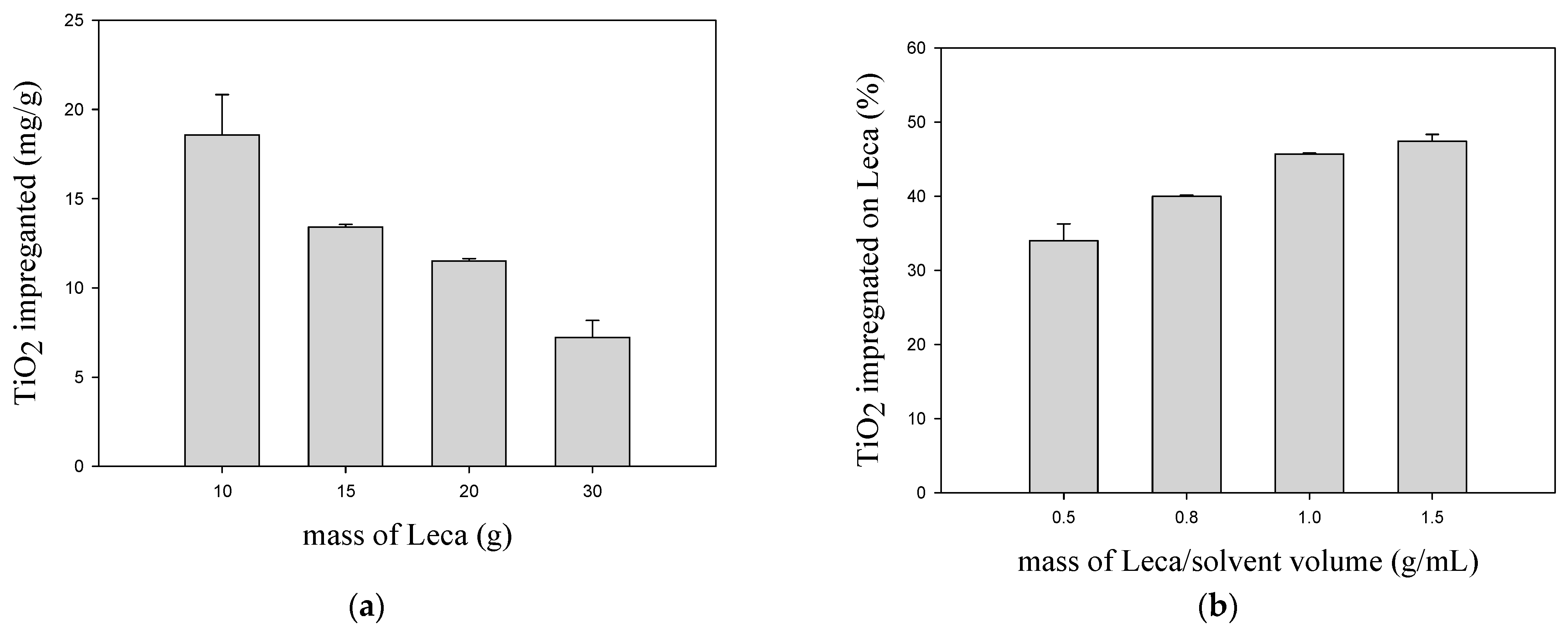
Figure 1a shows that the increase in the Leca amount leads to a decrease in the TiO
2 impregnated mass per gram of Leca. The best results were obtained using 10 g of Leca, where about 19 mg of TiO
2/g of Leca was impregnated. The turbulence generated during the boiling of solvent improves the contact between Leca and TiO
2 suspension, enhancing the redistribution of TiO
2 along with the support particles. However, this process is more effective for the case of 10 g of Leca since all the particles are always in contact with TiO
2 suspension. For higher loads, some particles of Leca are not immersed in the TiO
2 suspension, which reduces the solid/liquid contact. In
Figure 1b, the percentage of TiO
2 impregnated was evaluated as a function of the ratio of Leca mass per solvent volume for different amounts of Leca. The solid/liquid (S/L) ratio varied from 0.5 to 1.5 g/mL. At a 0.5 ratio, 34% of TiO
2 in the suspensions was impregnated, while 47% was verified in the case of 1.5 due to the higher number of Leca particles in contact with the suspension. Increasing the S/L ratio three times does not mean a consequent increase in the TiO
2 impregnation yield (
Figure 1b). Consequently, the increase in the Leca load significantly decreases the TiO
2 impregnated weight per g of Leca (
Figure 1a). Considering these results, the impregnation method that used 10 g of Leca in contact with the TiO
2 suspension was selected in the subsequent tests.
3.1.3. Effect of the Time and Contact Method on TiO2 Impregnation
The effect of time and type of contact (mixing) between the Leca and the TiO2 suspension in ethanol are relevant parameters in synthesizing the supported catalyst. The type of contact is crucial to guarantee the turbulence of the solution to enhance the TiO2 impregnation over all the surface of Leca particles. In this way, an ultrasonic bath and the shaker were used. These tests were carried out for 10 g of Leca in contact with 3.6% TiO2. Different contact times were considered in these experiments, from 15 to 120 min, and compared with no mixing, consisting only of adding Leca with TiO2 suspension without any kind of mixing. It should be noted that the times in question are not cumulative. Regarding the shaker method, the incorporations did not show promising results, ranging from about 12 to 14 mg of TiO2/g of Leca, which reveals that impregnation was lower than without any mixing. This is due to the type of movement used, causing TiO2 aggregation and some degree of sedimentation. Thus, a fraction of TiO2 will not be available to adhere to the surface of Leca.
The best results were obtained with an ultrasonic bath, with a TiO
2 impregnated mass for 15 and 120 min of about 22 to 23 mg/g Leca, respectively (
Table 1). The ultrasound waves can enhance the dispersion of nanoparticles of TiO
2 P25 onto the Leca surface and reduce the agglomeration of the nanoparticles, uniformizing the immobilization onto the support. This improvement can be related to the acoustic cavitation created by ultrasound waves which will create nanobubbles and collapse them to generate solvent microjets [
34]. These microjets will drive the nanoparticles against the Leca support improving its immobilization [
34,
35]. Sene et al. [
35] immobilized TiO
2 onto clinoptilolite support, and the presence of ultrasound guaranteed a uniform morphology and a more homogeneous dispersion. Othman et al. [
36] have highlighted the effect of increased ultrasonic amplitude in improving the stability of suspensions and uniformity in the glass coating process. It can be inferred that the frequency with which the ultrasonic waves are emitted promotes vibrations that allow for better dispersion of TiO
2 in ethanol. However, in the ultrasonic contact method, it was noted that no significant differences in the amounts of impregnated TiO
2 occurred as the agitation time increased. According to Tukey’s test, the
p-value is 0.1055 > 0.05, and it can be concluded that there are no significant differences between the average of the replicates of the samples in question. This fact demonstrates that 15 min of ultrasound is suitable and was adopted in the further stages of the impregnation method. Higher exposure times to ultrasounds will increase the preparation costs without relevant benefits.
3.1.4. Effect of the Solvent Type
For obtaining a stable suspension of TiO
2 for the preparation of the photocatalysts, it is indispensable the utilization of a solvent. A homogeneous dispersion is crucial to achieving an effective impregnation of the porous ceramic material due to the small size of TiO
2 nanoparticles. In the present work, ultrapure water and ethanol were tested as solvents. Ethanol as a solvent can enhance the nanoparticle’s dispersion since these nanoparticles tend to agglomerate, reducing the impregnation yield. The water was considered due to the widespread usage to disperse powders and the cost availability. The impregnation of 10 g of Leca at 3.6%TiO
2, using water as a solvent, led to 15.5 mg/g of Leca, while with ethanol, 18.1 mg/g of Leca was attained. Thus, it was concluded that ethanol is a better solvent than water. In the literature, some studies tested water [
37,
38], but others tested ethanol [
25,
38]. The main reason for the better performance of ethanol is due to the decrease of zeta potential values of nanoparticles, improving the stability and viscosity of the suspension [
38]. These effects will improve the coating process of ceramic material. Moreover, both catalysts produced with water and ethanol as solvent were tested in the photocatalytic process through a reactor described in the material and methods section for 120 min (degradation results not shown). After this, the loss of TiO
2 impregnated mass for ethanol and water was about 2 and 20 mg, respectively. Thus, ethanol seems to be the best solvent for TiO
2 impregnation.
3.1.5. Effect of Drying Temperature
The drying step is a relevant stage for solvent removal. The drying temperature can influence the distribution of TiO2 suspension over Leca particles due to the turbulence that can promote inside the contact vessel. The solvent used to disperse the TiO2 nanoparticles was ethanol, with a boiling temperature of about 78 °C. In order to evaluate the impact of drying temperature in the TiO2 impregnated mass, two different temperatures were tested: above (105 °C) and below (65 °C) ethanol boiling point. The procedure for testing the drying temperature consists of placing the TiO2 suspension contacted with Leca for 15 h at 105 °C. When a lower drying temperature was tested, the procedure was divided into two steps: the suspension plus Leca were placed at 65 °C for 15 h, and then the temperature was increased to 105 °C for 3 h to guarantee the complete solvent removal. For these experiments, suspensions with 3.6% TiO2 were prepared and contacted with 10 g of Leca using an ultrasonic bath for 15 min. Using 105 °C for 15 h led to about 23.9 mg/g of impregnation, while at 65 °C followed by 105 °C led to 20.3 mg/g. This allows us to conclude that keeping the oven at 105 °C is the most effective method since a greater amount of TiO2 covers the surface of Leca compared to the two stages method. For the drying temperature of 65 °C, the difference in the uniformity of coating is noticed. Some particles of Leca remained uncovered with TiO2, while others presented a huge accumulation of TiO2. The difference is because at 105 °C, ethanol boils, and this process promotes the redistribution of TiO2 on the Leca surface due to the turbulence improvement. This favors the adsorption of TiO2 onto the Leca particles. At 65 °C, this effect is limited due to the slow evaporation of ethanol. Thus, it can be inferred that drying at 105 °C had a better effect on the amount of TiO2 impregnated in Leca.
3.2. Effect of TiO2 Suspension Load
The concentration (load) of TiO
2 in the suspension can influence the thickness and uniformity of the impregnated layer of nanoparticles onto the Leca surface. In this sense, different loadings (1%, 3.6%, 5% and 10%
w/
w) were tested, giving rise to the nomenclature (1%TiO
2/Leca, 3.6%TiO
2/Leca, 5%TiO
2/Leca, 10%TiO
2/Leca). The average TiO
2 mass impregnated was determined by mass difference.
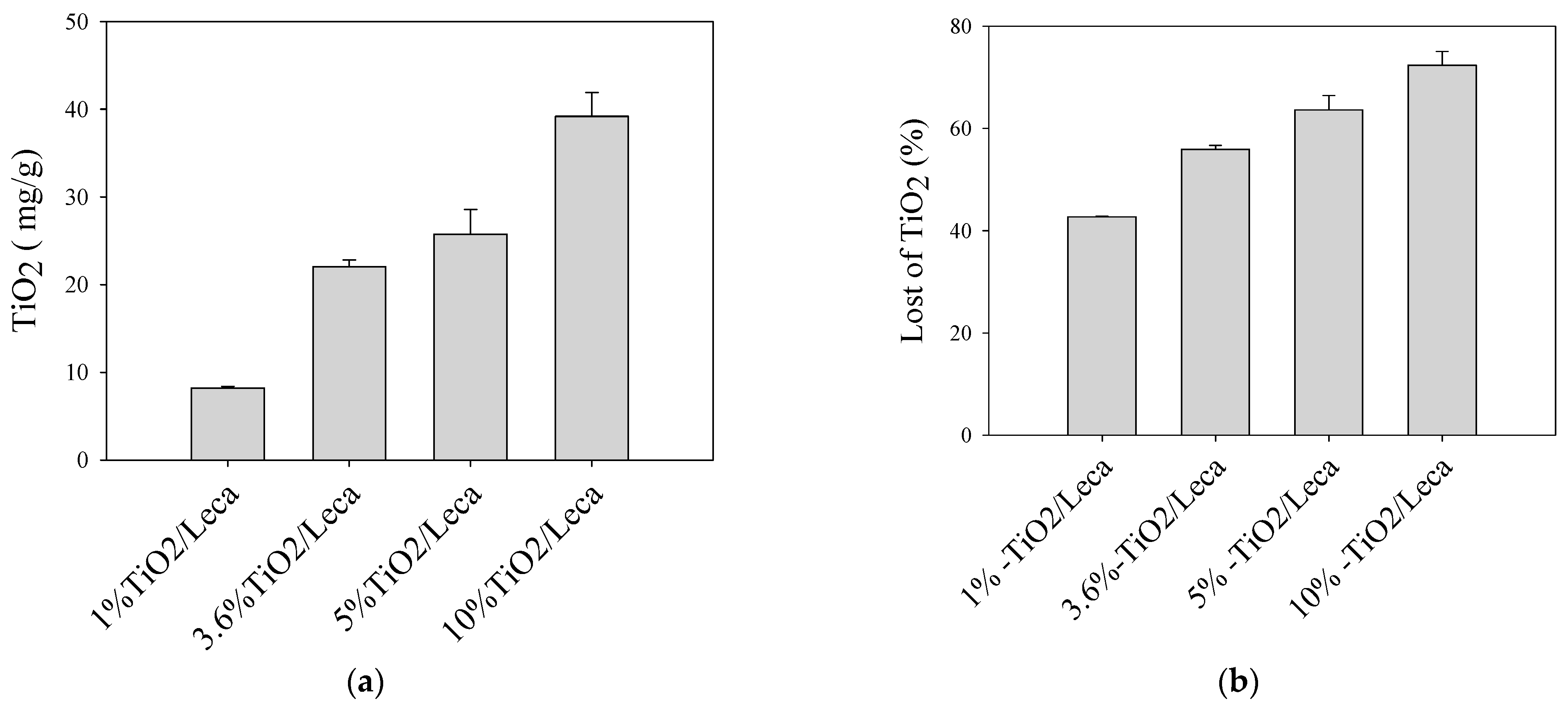
Figure 2a shows that the average of the TiO
2 impregnated mass at 1% (
w/
w) was supported 8.21 mg/g; 22.03 mg/g for (3.6%
w/
w); 25.76 mg/g for 5% (
w/
w); 39.20 mg/g for 10% (
w/
w). Thus, from the point of view of the impregnated TiO
2 load, the 10%TiO
2/Leca is the best option, and 1%TiO
2/Leca is the worst. The load of TiO
2 impregnated over the Leca surface gradually increased with the concentration in the dispersed suspensions. This effect may be associated with the viscosity of the suspensions and the structure of the Leca, which contains pores of different sizes and with roughness allowing the increment in the coating of TiO
2 particles. According to Zhou et al. [
39], the viscosity of TiO
2 suspensions increases as a function of TiO
2 load due to the high solid content of the suspensions, increasing the crosslinking density between the particles.
Figure 2b illustrates the mass loss of TiO
2 (not impregnated in the ceramic support) in the preparation process. This weight percent ratio considered for TiO
2 calculation was made after the calcination-wash stage. This means that although the impregnation increases with the concentration in the suspension (1%, 3.6%, 5%, and 10%), the loss of TiO
2 also increases from 43% to 72%, respectively. The increase of TiO
2 load promotes a rise of the TiO
2 loss that was not immobilized and will be considered a waste, contributing to a rise in the cost of preparation. Besides this, the higher concentrated suspensions were tested in terms of performance for the photocatalytic oxidation of SMX.
3.3. Photocatalytic Activity Assessment
After the preparation of the supported catalysts, the photodegradation of SMX was investigated under UVA radiation to assess the photocatalytic oxidation performance of TiO
2-Leca. However, powder TiO
2 was also tested as a catalyst for comparative purposes.
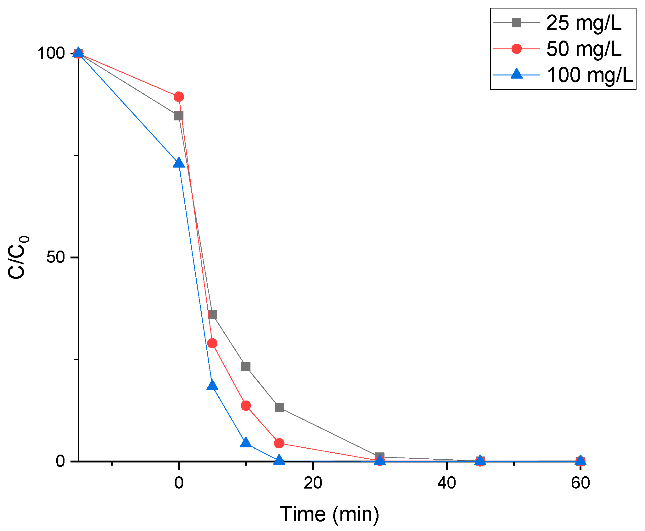
Figure 3 shows SMX abatement during experiments using different loads of powder TiO
2 P25 (25, 50, and 100 mg/L). These amounts were selected to compare with the TiO
2 impregnation loads on the Leca surface. For example, 3.6%TiO
2/Leca could impregnate 22.03 mg of TiO
2/g of Leca, meaning 10 g of Leca was available for 220.03 mg of TiO
2. The reactor used in the experiments works with 2 L of volume solution where the usage of 10 g of Leca represents a TiO
2 concentration of about 110 mg/L.
An adsorption test of 15 min to the catalyst in dark conditions was performed before the photocatalytic oxidation test. During this period, it was possible to see an increase in the adsorption of the catalyst load. It did not exceed 20% of the SMX removal for the highest TiO2 load. After this period, the removal of SMX was due to oxidation by photocatalysis.
It was observed that after 30 min of irradiation of the SMX solution, 100% degradation was achieved regardless of the applied TiO
2 powder load in the range of 25–100 mg/L. However, the initial degradation rate increases with catalyst load, which can be explained by the increase of active sites available for the hydroxyl radical’s production, allowing SMX efficient degradation [
40]. Abellán et al. [
41] applied 100 mg TiO
2/L for the degradation of 100 mg/L of the SMX under UV light and reached about 40% of degradation for 2 h.
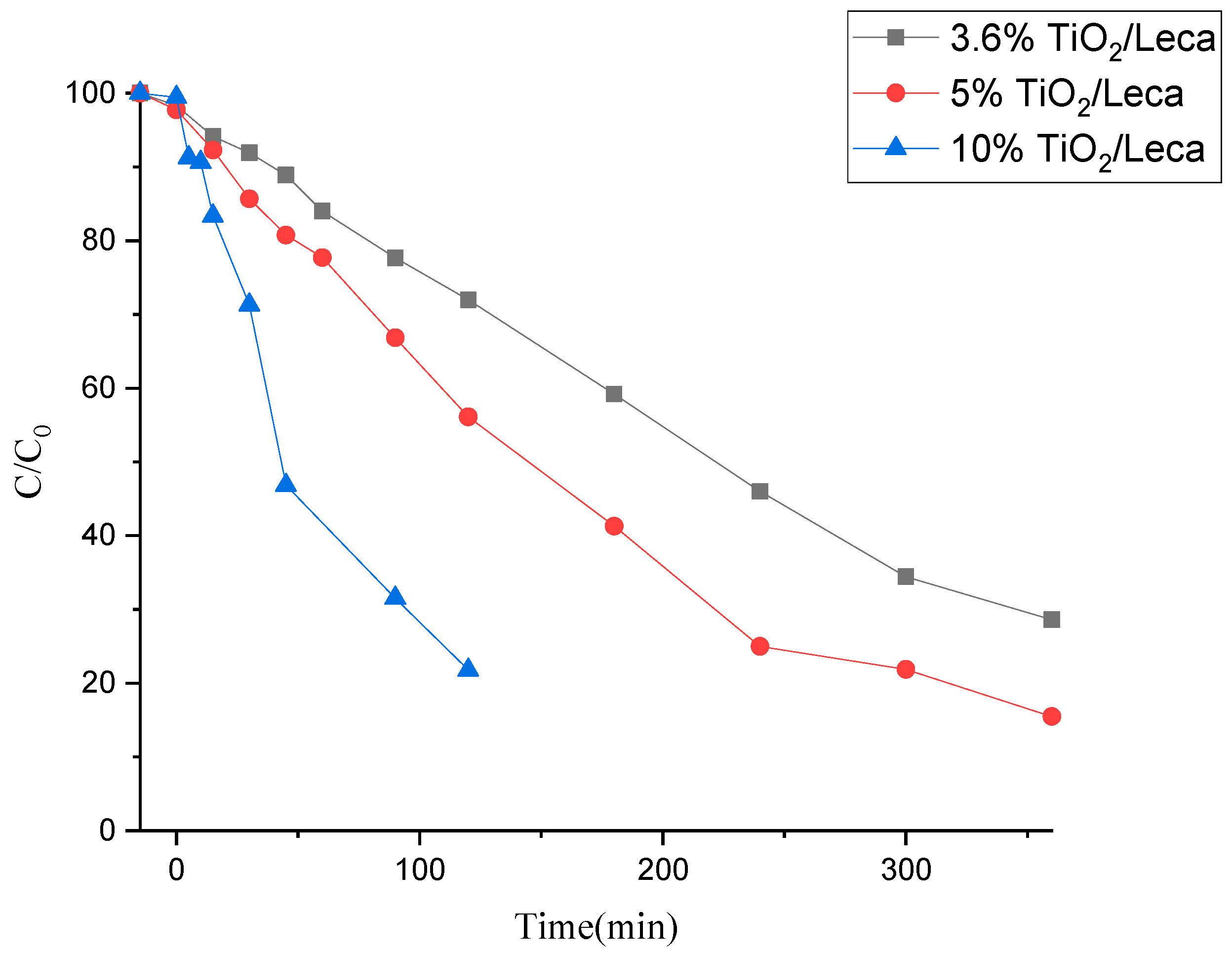
Then, the photocatalytic efficiency of the prepared photocatalysts (3.6%TiO2/Leca, 5%TiO2/Leca, 10%TiO2/Leca) was investigated during the degradation of the SMX under UVA radiation. However, considering that 1%TiO2/Leca was the one with a lower load of impregnated TiO2, its photoactivity was not evaluated in the SMX degradation tests.
The process was initiated by testing the adsorption effect of the photocatalyst. For that, the catalyst was in contact with an aqueous solution of SMX during the first 15 min without any radiation source. Afterward, the UVA light source was turned on, irradiating the photocatalysts in contact with the SMX solution. The results presented in
Figure 4 show that the SMX adsorption onto the catalyst surface is negligible since no reduction of SMX was verified until 0 min, contrary to what happens when TiO
2 is used as a powder (
Figure 3). This indicates that the degradation can occur on the catalyst surface and/or liquid bulk by forming reactive species.
Regarding the photocatalytic efficiency levels, they indicate degradation values ranging from 28, 43, to 78% for 2 h, with supported amounts of 86.6 mg/L (3.6%TiO2/Leca), 102.5 mg/L (5%TiO2/Leca) and 169.1 mg/L (10%TiO2/Leca). The 10%TiO2/Leca shows to be very effective in the degradation process of SMX, achieving about 78% of removal in 2 h. However, at the end of the experiments, a significant loss of TiO2 (about 169.1 mg from 348 mg as the initial amount) from the surface of the support was observed in the reactor due to the friction between the particles causing erosion. This fact results from the densification in the TiO2 coating on the ceramic support during the impregnations. Moreover, considering SMX removal and TiO2 loss in aqueous media results, the most promising photocatalysts were those incorporated at 3.6 and 5%w/w. In this case, as the erosion is almost negligible, the degradation is related to the supported photocatalyst, not the TiO2 erosion, as with the 10% w/w load.
Still, in
Figure 4, comparing the degradation curves between the photocatalysts (3.6%TiO
2/Leca and 5%TiO
2/Leca), it is noted that 71 to 85% of SMX were degraded over 6 h, and the 5%TiO
2/Leca presents better efficiency during the degradation process. It was observed that the amount of supported TiO
2 load and irradiation time influence the performance of the photocatalytic activity and the amount of SMX potentially degraded. Therefore, according to Chairungsri et al. [
42], TiO
2 nanoparticles coated on fixed substrates (glass and iron beads) lose many active sites from the surface binding site between the catalyst and the substrate, thus contributing to the reduction of the degradation rate. Similar conclusions were obtained by Zendehzaban et al. [
25] with removal rates of 85% ammonia for 5 h in a fluidized system, with 30 g of Leca coated with TiO
2 at pH 11. Other authors, Mohammadi et al. [
43], have found that for effective ammonia removal, the dosage of the hybrid catalyst (TiO
2-ZnO/Leca) was varied from 15 to 35 g/L with pH 11 solution and 180 min of UV irradiation.
Furthermore, the low efficiency of immobilized ceramic material compared to the TiO2 powder can be a suitable alternative to powder since it can be reused without significant TiO2 loss from the Leca surface. Therefore, it can be concluded that the photocatalyst prepared by the impregnation method represents a good alternative to solve the limitations of using powder catalysts. However, there is a need to optimize photocatalytic processes to improve their suitability for wastewater treatment and reuse them without the need for added chemicals.
3.4. Catalysts Characterization
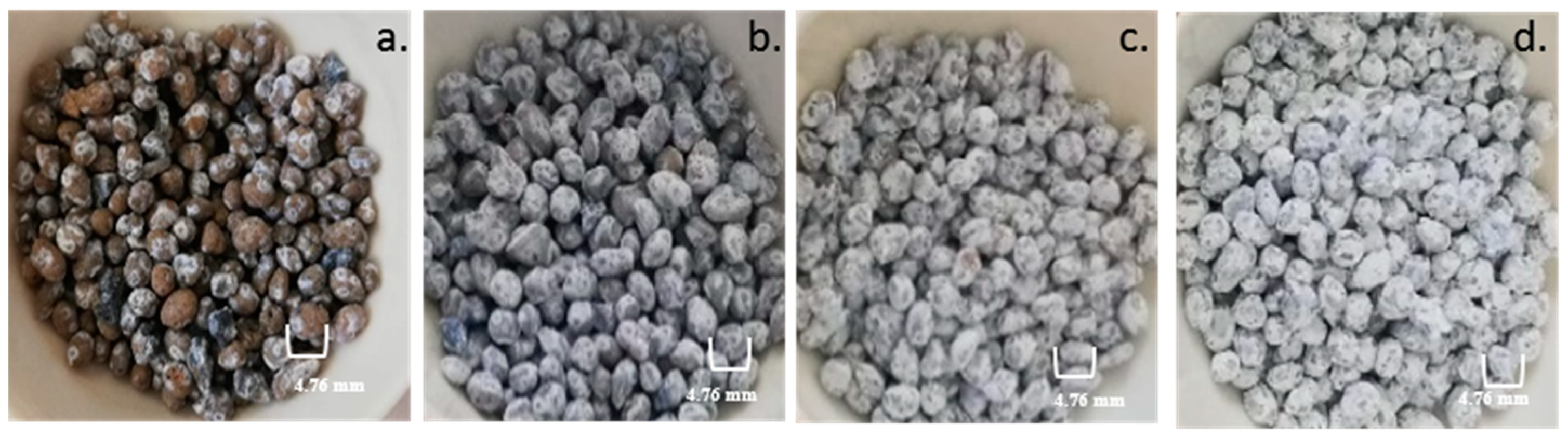
In order to evaluate the quality of TiO
2 impregnation, it is important to make a visual evaluation of Leca particles after impregnation. The external morphology and surface characteristics can be observed in
Figure 5, showing pictures of the Leca surface after coating with different TiO
2 loads (1%
w/
w, 3.6%
w/
w, 5%
w/
w, and 10%
w/
w). It is observed that for the 1%
w/
w impregnation load (
Figure 5a), the coated surface is partially devoid of TiO
2.
Figure 5b–d illustrates the significant degree of TiO
2 Leca surface covering, with the intensity of the shade proportional to the percentage of TiO
2 in the prepared suspensions. The increase in the TiO
2 load means more availability of active sites to produce the reactive species during photocatalytic oxidation with suitable radiation. Moreover, after coating Leca with TiO
2 (independent of the load), particles maintain float characteristics in the aqueous matrix.
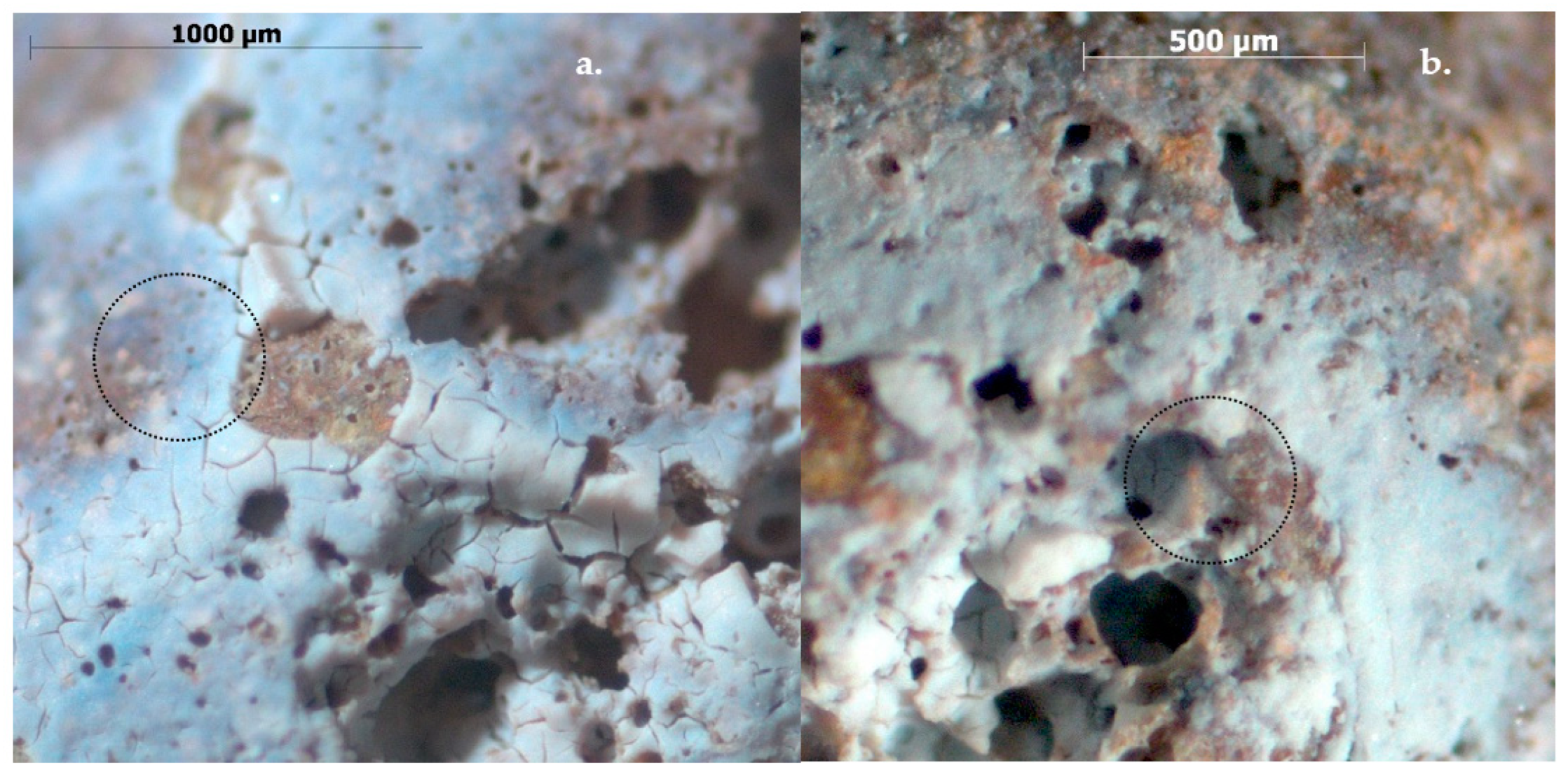
Using the Zeiss Stemi 2000-C magnifier,
Figure 6 depicts the effects of solvent (water and ethanol) on the photocatalysts synthesized at 3.6%. The poor adhesion of the coating layer can be seen in the section highlighted in
Figure 6a. This fact may be associated with reducing the repulsive potential (decrease in the zeta potential) that ethanol promotes between particles in suspensions that allow for maintaining adequate stability of the suspension to the coating process [
38].
Figure 6b shows a more homogeneous TiO
2 surface when ethanol is used as a solvent in the preparation.
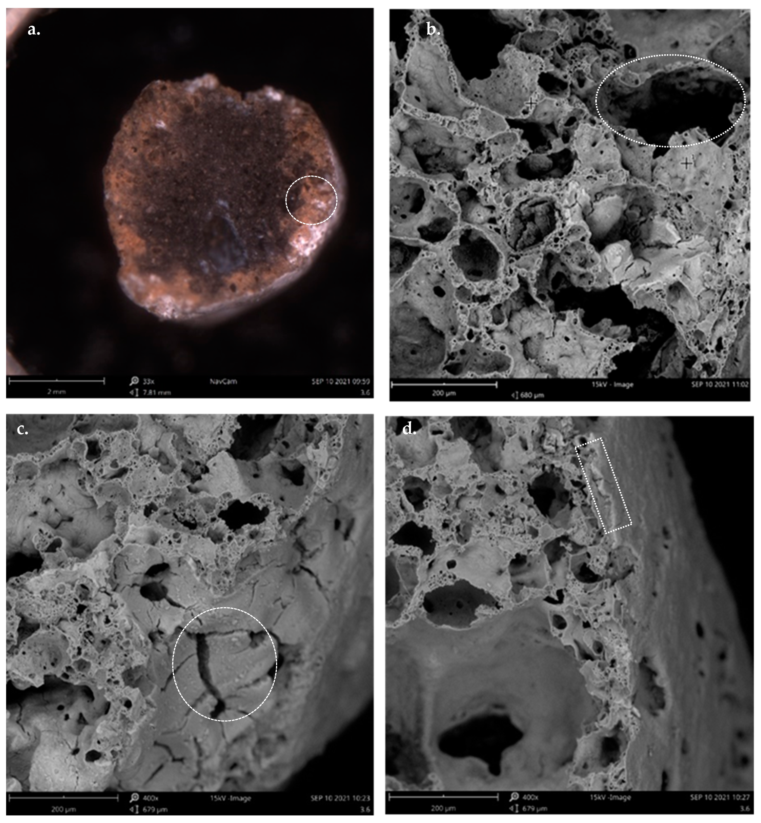
The SEM images for 3.6%TiO
2/Leca illustrated in
Figure 7 shows the photocatalysts’ morphology and structure. In particular,
Figure 7a highlights the surrounding cross-section of the photocatalyst, which indicates that the TiO
2 may penetrate deep into the Leca support.
Figure 7b shows that the Leca particle’s core structure presents high porosity with varied dimensions of pores. After the impregnation, the internal porosity of the support remained high. Similar results of TiO
2 immobilization on ceramic supports have been reported by Mohammadi et al. [
43].
Figure 7c shows that the photocatalyst surface shows small cracks, which may be associated with tensile stress due to capillary forces resulting from solvent evaporation and densification of the TiO
2 film during drying. Despite the lack of references in the literature regarding the effect of drying of alcoholic suspensions of TiO
2 on ceramic substrates, the occurrence of cracks with dimensions of 1.2 μm on the surface of the TiO
2 coated glass was reported by [
44,
45].
Figure 7d depicts that the TiO
2 coated film is not uniform, with the thickness layer changing along the surface of the support.
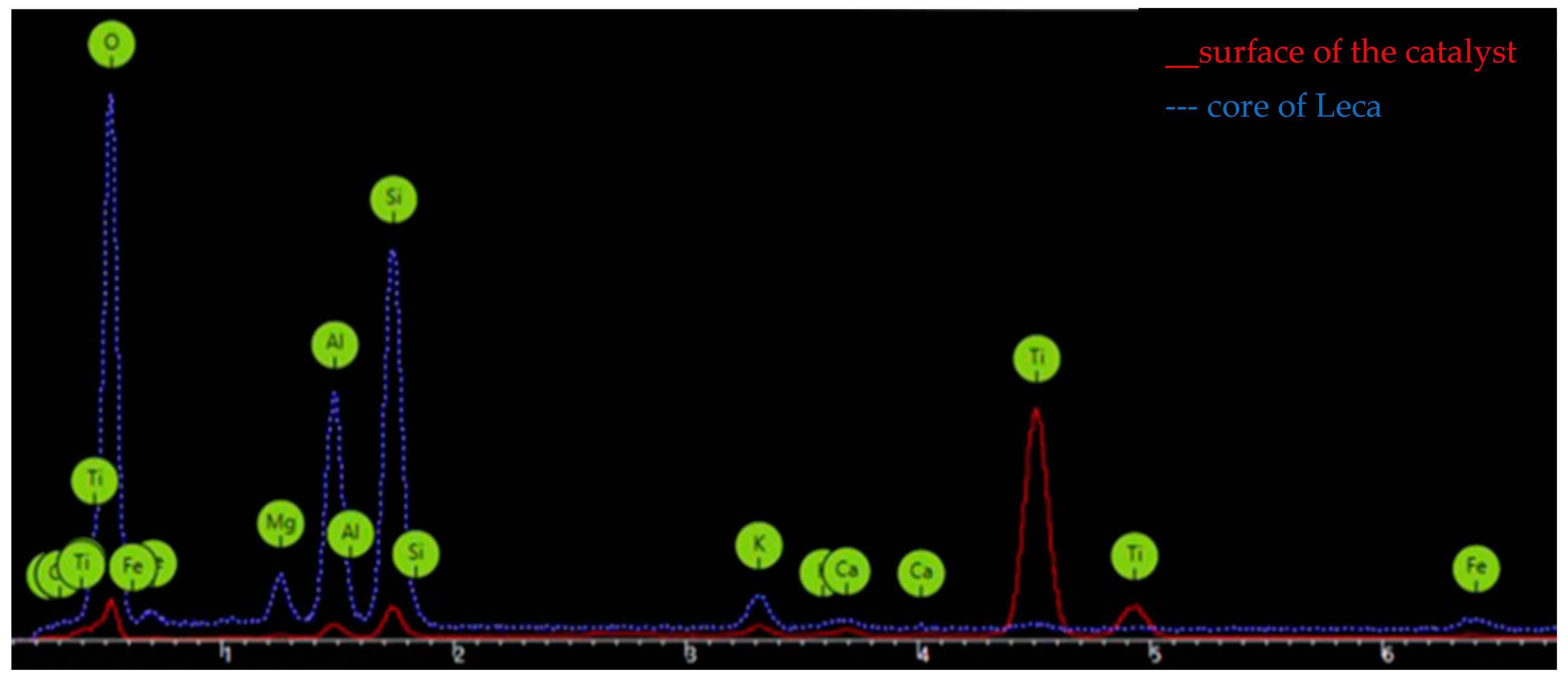
Figure 8 shows the results from the analysis using EDX of the Leca surface for the impregnation of TiO
2 with a 3.6%
w/
w load. We compared the elemental composition of the surface particles before and after impregnation with TiO
2. Silicon, aluminum, and oxygen are the most abundant elements in the core of the Leca particles, and these elements are combined in the form of oxides [
23]. However, at the surface of the catalyst impregnated with the TiO
2, the presence of titanium was evident in great amounts since the peak intensity was high.
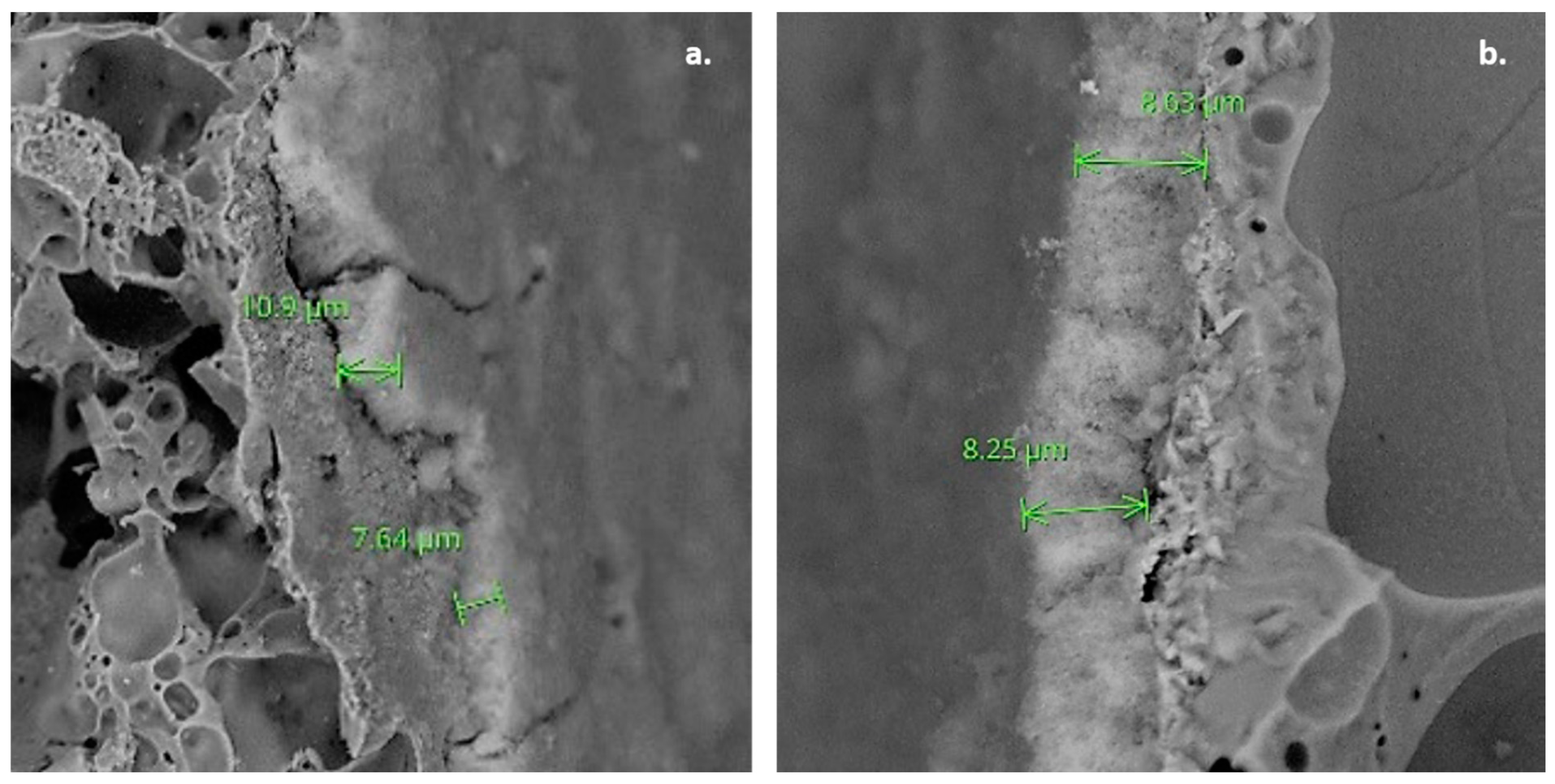
In order to analyze the impact of TiO
2 loads onto the Leca surface during the impregnation, the thickness layer for the immobilized TiO
2 onto the support using loads of 3.6%
w/
w and 5%
w/
w was also measured (
Figure 9). The layer thickness for both loads is very similar despite the difference in the TiO
2 impregnated amount. This means that for the considered TiO
2 loads, there are no improvements in the TiO
2 layer thickness. Moreover, the 3.6%
w/
w reveals that the layer is not uniform since the thickness ranges between 7.6 and 10.9 µm (
Figure 9a). On the other hand, the different points selected for 5%
w/
w show a more uniform layer thickness between 8.03 and 8.25 µm (
Figure 9b). This result indicates a better dispersion was obtained for 5%
w/
w than 3.6%
w/
w. When considering the photocatalytic oxidation using different TiO
2 loads, the 5%
w/
w shows a higher degradation rate of SMX compared with the 3.6%
w/
w (
Figure 4).
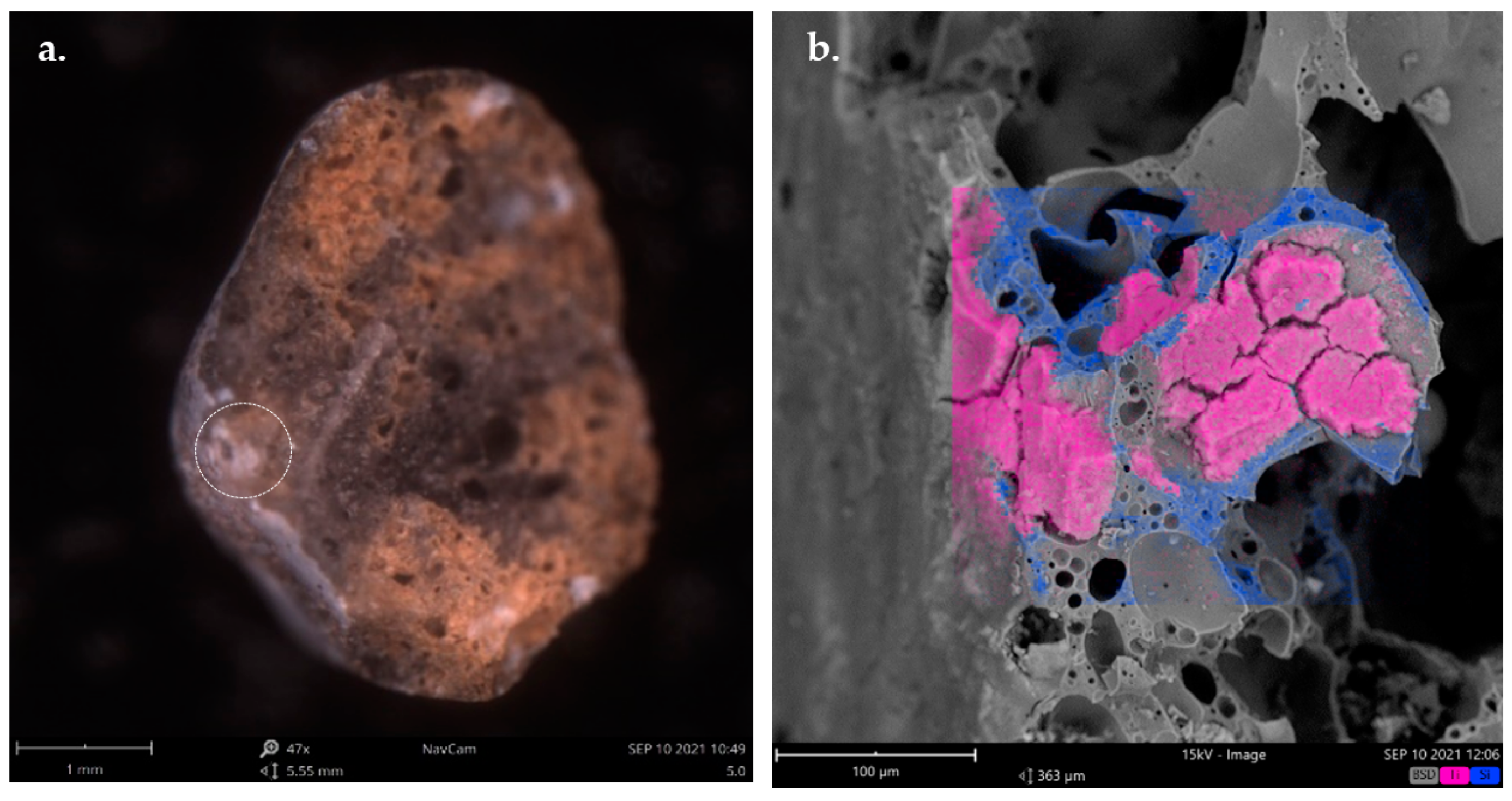
Figure 10 shows a SEM image with elemental chemical mapping highlighting the TiO
2 coating of a surface pore. In particular, the pink color represents the distribution of Ti in the Leca particle, while the blue color marks the distribution of Si. The mapping reinforces the evidence that in the chemical composition of the 5% TiO
2/Leca structure, the most abundant elements are Ti and Si. The surface of the cut section highlighted in the circle of
Figure 10a reveals that TiO
2 does not remain on the surface only. This is due to the connectivity of pores of the Leca from the surface to deeper zones of the particle. Moreover,
Figure 10b proves that the TiO
2 impregnated enters the pore (marked section in
Figure 10a) and occupies it in great deep, meaning that TiO
2 can continue in the Leca during different cycles of use.
4. Conclusions
Based on the results, it can be concluded that the impregnation method applied in the synthesis of photocatalysts is effective and that the catalysts produced can be applied in the treatment of contaminants of emerging concern (such as SMX) in liquid effluents. Moreover, the preparation steps before and during the impregnation method are very relevant to increasing the amount of TiO2 immobilized on the Leca surface. SEM images reveal the adhesion of TiO2 films and high porosity of Leca® S before and after impregnation, as well as a varying thickness of the supported TiO2 layer from 7.64 to 10.9 μm. The increase of TiO2 load in the suspension enhances the amount of impregnated TiO2 onto the Leca surface. It also increases the loss of TiO2 from the Leca at the end of the photocatalytic reactions.
The performance of TiO2 supported on Leca® S in the degradation of SMX in ultrapure water depends on the radiation time, and the concentration of TiO2 supported in the reactor. The photocatalysts achieved a degradation rate of SMX in the order of 28 to 43% after 2 h of reaction, using 86.6 mg/L of 3.6%TiO2/Leca and 102.5 mg/L 5%TiO2/Leca, respectively.
It is expected that the optimization of the photoreactor configuration may favor the yield of the degradation, namely by improving the photon absorption, agitation, and the type of radiation used.


 ,
, 


