Communication

Improved Interaction Formula for the Plastic Resistance of I- and H-Sections under a Combination of Bending Moments My,Ed, Mz,Ed, and Bimoment BEd

1
Department of Continuous Medium Mechanics and Theory of Structures, Universitat Politècnica de València, c/Camino de Vera s/n, 46022 Valencia, Spain
2
Department of Metal and Timber Structures, Faculty of Civil Engineering, Slovak University of Technology in Bratislava, 81005 Bratislava, Slovakia
3
Department of Structural Mechanics, Faculty of Civil Engineering, Slovak University of Technology in Bratislava, 81005 Bratislava, Slovakia
*
Author to whom correspondence should be addressed.
Appl. Sci. 2022, 12(15), 7888; https://doi.org/10.3390/app12157888
Submission received: 14 July 2022 / Revised: 1 August 2022 / Accepted: 2 August 2022 / Published: 6 August 2022
(This article belongs to the Special Issue State-of-the-Art in Structural Steel Engineering)

Abstract

:
The resistances of HVH sections (H—horizontal upper flange, V—vertical web, H—horizontal bottom flange) were investigated by the authors in the frame of the large parametrical studies focused on the complete HVH-section categories: channels, Z-sections, I-sections, and H-sections. The three different variants of the approximate formulae for the calculation of the elastic and plastic resistances of I-shaped sections loaded by several internal forces were previously published by the authors. In this paper, the improved approximate formulae are presented for the plastic resistance of I- and H-sections loaded by bending moments My,Ed, Mz,Ed, and bimoment BEd. It is shown in the graphical form that the proposed approximate formulae give almost identical values of relative plastic resistances of I-shaped sections to the exact solution, in which Pattern Search Algorithm, offered by MATLAB, is used. It is proven that the proposed approximate formulae are better then previous authors’ formulae, which are themselves better than the older Greek proposal and the newer German proposals. The approximate formulae may be used in the CEN Technical Specification (TS) or in Non Contradictory Complementary Information (NCCI) for supporting safe and economical design according to metal (steel and aluminum) Eurocodes.

1. Introduction

The current metal Eurocodes [1,2] do not contain rules for the calculation of the plastic resistance of members loaded by a combination of bending moment(s) and bimoment. Eurocode [1] contains only a conservative linear-interaction formula (Equation (6.2) in [1]). Equation (6.2) is valid for class 1, class 2, or class 3 cross sections subjected to the combination of NEd, My,Ed, and Mz,Ed. According to the Eurocode [1]: “The plastic resistance of cross sections should be verified by finding a stress distribution which is in equilibrium with the internal forces and moments without exceeding the yield strength. This stress distribution should be compatible with the associated plastic deformations” (cl. 6.2.1(6) in [1]). Similar clauses are missing in [2].
Both drafts of the new generation of Eurocodes [3,4] contain the equations for the calculation of the design bending moment reduced by the bimoment. In cl. 8.2.7(7) [3], the authors state: “For Class 1 or Class 2 symmetric I-cross-sections in bending about the major axis, the design plastic bending moment resistance Mc,B,Rd reduced by the bimoment BEd may be calculated from Formula (8.29)”. Formula (8.29) is the second Formula (3) in this paper, and the history of its development is described below. The draft of the Eurocode [4] applies a similar formula (see formula (8.38) in cl. 8.2.7(6) [4]). Both drafts of the Eurocodes [3,4] contain the following the sentence: “For determining the plastic moment resistance of a cross-section due to bending and torsion, only torsion effects BEd should be derived from elastic analysis” (see 8.2.7(6) in [3] or 8.2.7(5) in [4]).
The need for an interaction formula for the calculation of the plastic resistance of the I-shaped section was solved by the authors in [5], in which three variants of the formula were presented, taking into account the influence of three internal forces: two bending moments, My,Ed and Mz,Ed, and a bimoment, BEd. In this paper, variant No.4 is developed, which is more exact than the previous variants, No.1, No.2, and No.3 published in [5].
In Table 1 in [5], the authors present three approximate formulae variants. Table 1 in [5] shows that variant No. 3 is the best. The purpose of this paper is to present variant No. 4, which is better than variant No. 3. Variant No. 4 is defined by the formulae in Table 1, below, and by the equations in (37). The approximate results agree well with the exact results obtained by linear programming (Figure 1 and Figure 2). Figure 1 and Figure 2 show also comparisons with the older results obtained by Vayas (Equations (9) and (21c) in [6]), and to the brand new results obtained by Ludwig (Equation (29) in [7]). We can see that the results of the proposed variant No. 4 fit the exact curves well (Figure 1 and Figure 2). The proposals of Vayas and Ludwig substantially differ within some intervals of the exact results.
It is worth mentioning that Ludwig informed us that he used paper [8]. He forgot to include [8] in the list of references in [7]. Moreover, Ludwig mistakenly referred to the formula in Table 6 [7] as Mirambell’s formula and referred to [26] ([9] here). The formula in this form is not found in [26]. In fact, it is Baláž’s formula, taken by Ludwig from [8], and not from [26]. Baláž’s formula was accepted for the last draft of prEN 1993-1-1 [2], where it replaced Mirambell’s original, incorrect formula (see Figure 3b in [8]). The exact solution of the plastic resistance of the section under a combination of several internal forces can be obtained by (a) dividing a section into three elements (upper flange, bottom flange, and web) and (b) using linear programming (Osterrieder [10]). Method (a) was applied by Yang, Chern, and Fan [11], Kindmann and Frickel [12], and Rubin [13] by taking into account up to eight internal forces [14]. The programs developed by DLUBAL [15] and Aguero [16] are based on the simplex method.

1.1. Linear-Interaction Formula

The conservative approach for all cross-section classes is represented by formula (6.2) in EN 1993-1-1:2005 [1]. It is the linear summation of the utilization ratios of all the components. For Classes 1 and 2, Formula (6.2) [1] takes, without the influence of the normal force NEd, the following form, if the bimoment BEd is added:
M y , E d M p l , y , R d + M z , E d M p l , z , R d + B E d B p l , R d 1

1.2. Proposals for Interaction Formula Containing My,Ed and BEd

Streľbickaja derived such a formula for channel and I-shaped sections. The formula for I-shaped sections is as follows:
( M y , E d M w , p l , y , R d M p l , y , R d M w , p l , y , R d ) 2 + B E d B p l , R d 1
Formula (2) was simplified by Baláž in the form (3) and was applied in [17,18,19,20,21].
( M y , E d M p l , y , R d ) 2 + B E d B p l , R d 1 ; M c , B , R d = 1 B E d B p l , R d M p l , R d
The first proposal (4) for the previous prEN 1993-1-1 draft was made by Mirambell, Bordallo, and Real [9], where relevant hypotheses are described in detail. In the derivation of Formula (4), the analogy was utilized between the stress distribution in a rectangle section due to normal force combined with bending moment and the stress distribution in the flange of an I-section due to the bending moment and bimoment in the plastic state. Formula (4) was the first approach to solve the bending–warping torsion interaction within the framework of prEN1993-1-1 [2]. This approach was proposed because it was simple and easy to use and because it also employed a formulation already implemented into EN 1993-1-1 [1] to consider the shear–torsion interaction.
M c , B , R d = 1 σ w , E d , max 1.25 f y γ M 0 M p l , y , R d
Working group EN 1993-1-1 finally accepted Formula (3), proposed by Baláž in the Formula (3).
In this paper, a generalization of Equation (3) also considers Mz,Ed, which needs to be taken into account when analyzing the behavior of unrestrained beams sensitive to lateral torsional buckling (Agüero et al. [22]).

1.3. Calculation of Factor ξ

In the ξ factor by which internal forces must be multiplied to reach the plastic resistance, the lower-bound theorem can be used.
This lower-bound procedure was applied in two methods: (i) Method A divides the section into elements whose stresses are unknown; (ii) Method B divides the section into three parts (flanges and web). In each part, the unknowns are the axial force and the bending moment.

1.3.1. Method A (According to Osterrieder et al.)

Step 1. Dividing section into elements.
Step 2. Considering linear constraints by Equations (5)–(9):
Limitation of normal stresses:
f y σ i f y
Equilibrium equations:
i = 1 n σ i A i = ξ N E d
i = 1 n σ i A i y i = ξ M z , E d
i = 1 n σ i A i ω i = i = 1 n σ i A i y i z i = ξ B E d
i = 1 n σ i A i z i = ξ M y , E d
Step 3. Calculation of maximum ξ:
max ( ξ )
The problem can be solved by linear programming.

1.3.2. Method B (According to Rubin and Kindmann et al.)

Method B is according to Rubin [13] and Kindmann et al. [23,24,25]), the computer programs in [15,16,25] give similar results.
The I-section consists of three parts: top flange–index Tfl, bottom flange–index Bfl and web–index w. In Method B, the following are calculated: factor ξ to accomplish plastic resistance, axial forces N { N T f l , E d ; N B f l , E d ; N w , E d }, and bending moments M in each part { M T f l , z , E d ; M B f l , z , E d ; M w , y , E d }.
Step 1. Dividing section into three parts.
Calculation of axial and bending resistances of all the parts:
N f l , p l , R d = N T f l , p l , R d = N B f l , p l , R d = b t f f y ; N w p l , R d = h w t w f y M f l , p l , z , R d = M T f l , p l , z , R d = M B f l , p l , z , R d = b 2 · t f · f y 4 ; M w , p l , y , R d = h w 2 · t w · f y 4
Step 2. Considering constraints:
Plastic resistances of the top flange in the nonlinear-interaction formula:
( N T f l , E d N T f l , p l , R d ) 2 + | M T f l , z , E d M T f l , p l , z , R d | 1
Plastic resistances of the bottom flange in the nonlinear-interaction formula:
( N B f l , E d N B f l , p l , R d ) 2 + | M B f l , z , E d M B f l , p l , z , R d | 1
Plastic resistances of the web in the nonlinear-interaction formula:
( N w , E d N w , p l , R d ) 2 + | M w , y , E d M w , p l , y , R d | 1
Equilibrium equations:
N T f l , E d + N B f l , E d + N w , E d = ξ N E d M T f l , z , E d + M B f l , z , E d = ξ M z E d h t f 2 ( M T f l , z , E d M B f l , z , E d ) = ξ B E d M w , y , E d + h t f 2 ( N B f l , E d N T f l , E d ) = ξ M y E d
Step 3. Calculation of maximum ξ:
max ( ξ )

1.4. Research Significance

The steps of Method A and Method B are described in detail. They make it possible to obtain the exact interaction formulae.
Three interaction formulae for the calculation of the plastic resistance of cross sections under the bending moment about the strong axis, My,Ed, the bending moment about the weak axis, Mz,Ed, and the bimoment, BEd, are compared for the beams with the I- and H-sections. The proposal is presented in Section 3.

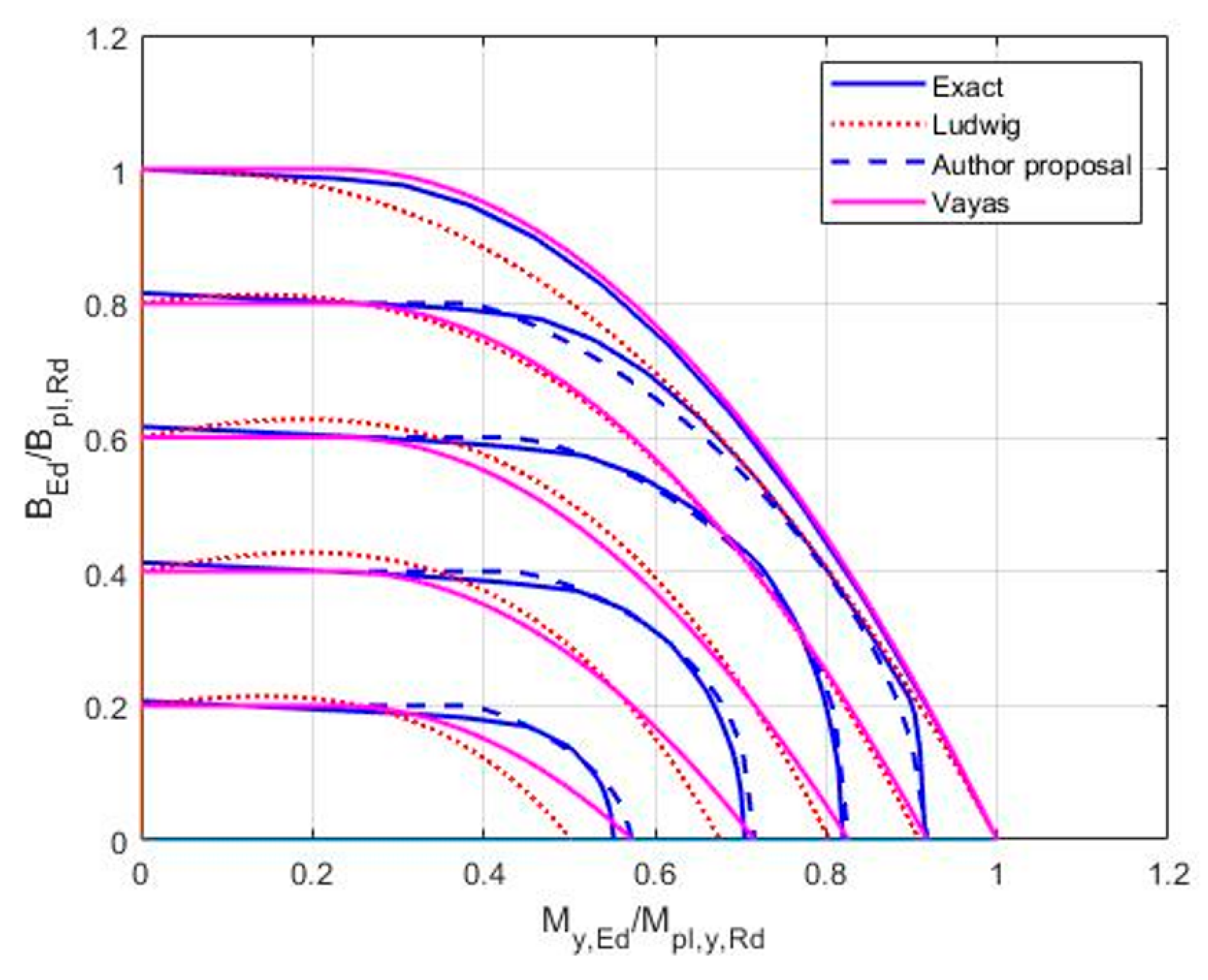
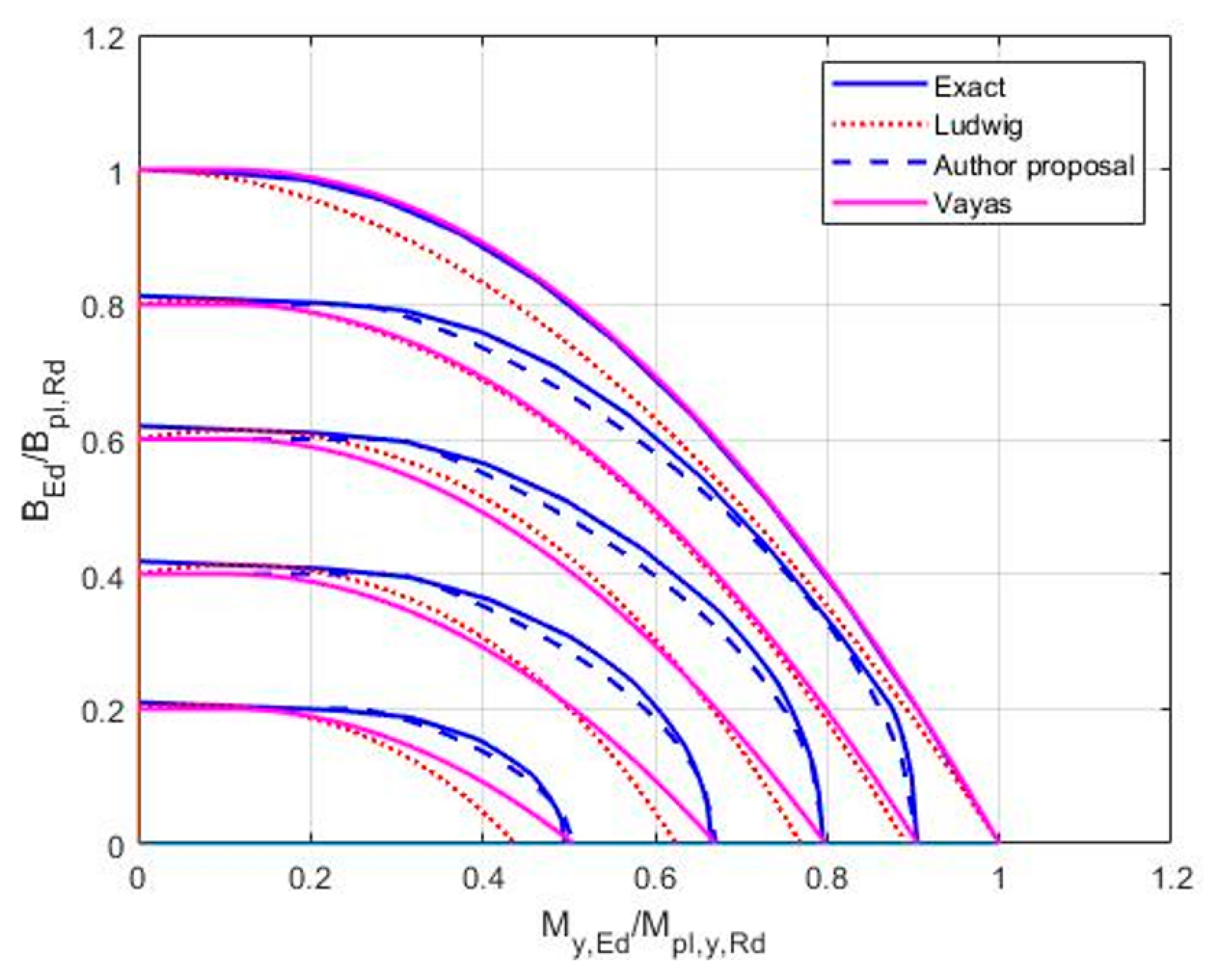
2. Calculation of Exact Interaction Curves

Method A is applied to obtain the interaction curves with parameter Mz,Ed
Step 1. Calculation of Mpl,z,Rd for the given NEd = 0.0, My,Ed = 0.0 and BEd = 0.0.
Considering constraints by Equations (17)–(20):
f y σ i f y
i = 1 n σ i A i = N E d = 0.0
i = 1 n σ i A i z i = M y , E d = 0.0
i = 1 n σ i A i y i z i = B E d = 0.0
Calculation of maximum Mz,Ed:
M p l , z , R d = max ( M z , E d ) = max ( i = 1 n σ i A i y i )
Step 2. Calculation of BEd,γ to achieve plastic resistance for the given NEd = 0.0, My,Ed = 0.0, Mz,Ed = γ·Mpl,z,Rd; γ [0,1]
Constraints Equations (22)–(25):
f y σ i f y
i = 1 n σ i A i = N E d = 0.0
i = 1 n σ i A i z i = M y , E d = 0.0
i = 1 n σ i A i y i = M z , E d = γ · M p l , z , R d
Calculation of maximum Bpl,Rd,γ:
B p l , R d , γ ( M z , E d ) = max ( i = 1 n σ i A i y i z i )
Step 3. Calculation of My,Ed,γ,η to achieve the plastic resistance for the given NEd = 0.0, BEd = ηBpl,Rd,γ, Mz,Ed = γ·Mpl,z,Rd; γ [0,1] and η [0,1].
Considering constraints by Equations (27)–(30):
f y σ i f y
i = 1 n σ i A i = N E d = 0.0
i = 1 n σ i A i y i = M z , E d = γ M p l , z , R d
i = 1 n σ i A i y i z i = B E d = η B p l , R d , γ
Calculation of maximum MyEdγ,η:
M y , E d , γ , η ( B E d ; M z , E d ) = max ( i = 1 n σ i A i z i )
Application of Method B:
Dividing the section into three parts (top flange, bottom flange, and web):
The axial force that leads to the plastic behavior of the top flange:
N T f l , E d = N f l , p l , R d 1 | M z , E d 2 M f l , p l , z , R d + B E d ( h t f ) M f l , p l , z , R d |
The axial force that leads to the plastic behavior of the bottom flange:
N B f l , E d = N f l , p l , R d 1 | M z , E d 2 M f l , p l , z , R d B E d ( h t f ) M f l , p l , z , R d |
If the axial force equals zero (NEd = 0), the axial force at the web will be as follows:
N w , E d = N T f l , E d N B f l , E d
The bending moment that leads to the plastic behavior at the web:
M w , y , E d = M w , p l , y , R d ( 1 ( N w , E d N w , p l , R d ) 2 )
The resultant bending moment My,Ed is then:
M y , E d = M w , y , E d + ( N T f l , E d + N B f l , E d ) ( h t f ) 2

3. Proposal for Improved Interaction Formulae (Variant No. 4)

The original formulae of variants Nos. 1, 2, and 3, presented in Table 1 [1], are improved by variant No. 4. In variant No. 4, the definitions of the parameters α, β, and δ are different. The improved formulae of variant No. 4 with the changed parameters (Equations in (37)) provide results that agree well with the exact results obtained by linear programming (Figure 1 and Figure 2).
Table 1. Improved interaction formulae with changed parameters α, β, and δ (variant No. 4).
0 M y , E d M p l , y , R d < δ δ M y , E d M p l , y , R d 1.0
B E d B p l , R d 1 M z , E d M p l , z , R d 1.0 ( M y , E d M p l , y , R d δ ( 1 M z , E d M p l , z , R d ( 1 M w , p l , y , R d M p l , y , R d ) + M w , p l , y , R d M p l , y , R d ) δ ) α + ( B E d B p l , R d 1 M z , E d M p l , z , R d ) β 1
where
{ α β δ } = { 2 1 M w , p l , y , R d M p l , y , R d } + { α * 2 β * 1 δ * M w , p l , y , R d M p l , y , R d } cos ( | M z , E d M p l , z , R d 0.5 0.5 | 1.5 π 2 ) { α * β * } = { 1.1 2 } + { 1 1 } 4 ( M w , p l , y , R d M p l , y , R d 0.1 ) ( cos ( | M z , E d M p l , z , R d 0.5 0.5 | π 2 ) ) 4 δ * = 0.2 + M w , p l , y , R d M p l , y , R d

4. Conclusions

The plastic resistance of the I- and H-sections under a combination of bending moments, My,Ed, Mz,Ed, and bimoment BEd, was investigated. The paper suggested an improvement to a previous proposal, published by the authors in [5], in which the three variants, No.1, No.2, and No.3, of approximate-interaction formulae were investigated. The proposed formulae may be called variant No.4. It was shown in graphical form that the proposed variant No.4 of the approximate Formula (37) gives almost identical values of the relative plastic resistances of I-shaped sections to the exact results obtained by linear programming (Figure 1 and Figure 2).
The comparisons of the results of the new approximate formulae with the results obtained by Vayas [6] and Ludwig [7] show that they agree better with the exact theoretical results, which were presented in the form of diagrams (Figure 1 and Figure 2).
The proposed Formulae (37) are rather complex and long. Therefore, they can hardly be accepted directly for the new generation of the metal Eurocode prEN 1993-1-1 design of steel structures [2] or the prEN 1999-1-1 design of aluminum structures [4]. However, they may be given in the CEN Technical Specification, and they may be part of the national Non Contradictory Complementary Information. The reason for this is that the approximate formulae and exact results of the submitted theory have useful practical applications. They enable the safe and economical design of steel and aluminum thin-walled structures. The exploitation of the plastic-section resistance reserves helps to save the structural material.

Author Contributions

Conceptualization, A.A. and Y.K.; Data curation, A.A., I.B. and Y.K.; Formal analysis, A.A., I.B. and Y.K.; Funding acquisition, Y.K.; Investigation, I.B.; Software, A.A. All authors have read and agreed to the published version of the manuscript.

Funding

This research, project no. 1/0453/20, is funded by the Slovak Grant Agency VEGA. The APC was funded by the Slovak Grant Agency VEGA, project no. 1/0453/20.

Institutional Review Board Statement

Not applicable.

Informed Consent Statement

Not applicable.

Data Availability Statement

Not applicable.

Acknowledgments

This research, project no. 1/0453/20, is supported by the Slovak Grant Agency VEGA.

Conflicts of Interest

The authors declare no conflict of interest.

Nomenclature

The nomenclature is according to Eurocode EN 1993-1-1.

References

  1. EN 1993-1-1:2005 and Corrigendum AC (2006) and Corrigendum AC (2009) and Amendment A1 (2014); Eurocode 3: Design of Steel Structures. Part 1.1: General Rules and Rules for Buildings. European Union: Brussels, Belgium, 2005.
  2. EN 1999-1-1:2007 and Amendment A1 (2009) and Amendment A2 (2013); Eurocode 9: Design of Aluminium Structures. Part 1.1: General Structural Rules. European Union: Brussels, Belgium, 2007.
  3. prEN 1993-1-1:2020; Eurocode 3: Design of Steel Structures. Part 1.1: General Rules and Rules for Buildings. European Union: Brussels, Belgium, 2020.
  4. prEN 1999-1-1:2022-01-14; Eurocode 9: Design of Aluminium Structures. Part 1.1: General Structural Rules. European Union: Brussels, Belgium, 2022.
  5. Agüero, A.; Baláž, I.; Koleková, Y.; Moroczová, L. New interaction formula for the plastic resistance of I- and H-sections under combinations of bending moments My,Ed, Mz,Ed and bimoment BEd. Structures 2021, 29, 577–585. [Google Scholar] [CrossRef]
  6. Vayas, I. Interaktion der plastischen Grenzschnittgrößen doppelsymmetrischer I-Querschnitte. Stahlbau 2000, 69, 693–706. [Google Scholar] [CrossRef]
  7. Ludwig, C. Assessment of the interaction conditions of i-shaped cross-sections. Eurosteel 2021, 4, 1085–1095. [Google Scholar] [CrossRef]
  8. Baláž, I.; Koleková, Y. Resistances of I- and U-sections. Combined bending and torsion internal forces. In Proceedings of the EUROSTEEL, Copenhagen, Denmark, 13–15 September 2017; pp. 1–10, Paper No. 13_12_ 772 on USB. [Google Scholar]
  9. Mirambell, J.E.; Bordallo, E. Real torsion and its interaction with other internal forces in EN 1993-1-1—A new approach. Steel Constr. 2016, 9, 240–248. [Google Scholar]
  10. Osterrieder, P.; Kretzschmar, J. First-hinge analysis for lateral buckling design of open thin-walled steel members. J. Constr. Steel Res. 2006, 62, 35–43. [Google Scholar] [CrossRef]
  11. Yang, Y.B.; Chern, S.M.; Fan, H.T. Yield surfaces for I-sections with bimoments. J. Struct. Eng. 1989, 115, 3044–3058. [Google Scholar] [CrossRef]
  12. Kindmann, R.; Frickel, J. Grenztragfähigkeit von häufig verwendeten Stabquerschnitten für beliebige Schnittgröβen. Stahlbau 1999, 68, 817–828. [Google Scholar] [CrossRef]
  13. Rubin, H. Zur plastischen tragfähigkeit von 3-blech-querschnitten unter normalkraft, doppelter biegung und wölbkrafttorsion. Stahlbau 2005, 74, 47–61. [Google Scholar] [CrossRef]
  14. Wolf, C.; Frickel, J. QST-TSV-3Blech. Program. Lehrstuhl für Stahl- und Verbundbau. Prof. Dr.-Ing. R. Kindmann. Ruhr-Universität Bochum. 2002. Available online: https://www.kindmann.de/downloads/file/1-rubstahl-programme (accessed on 13 July 2022).
  15. Dlubal Software GmbH. Programm SHAPE-THIN 8. German name DUENQ, 8.13.01.140108 x64. 2018. Available online: https://dlubl.com/en/products/cross-section-properties-software/shape-thin (accessed on 13 July 2022).
  16. Agüero, A.; Gimenez, F. Thinwallres. 2022. Available online: https://labmatlab-was.upv.es/webapps/home/thinwallres.html (accessed on 13 July 2022).
  17. Baláž, I.; Kováč, M.; Živner, T.; Koleková, Y. Plastic resistance of H-section to interaction of bending moment My,Ed and bimoment BEd. In Proceedings of the 2nd International Conference on Engineering Sciences and Technologies, High Tatras Mountains, Tatranské Matliare, Slovakia, 29 June–1 July 2016; CRC Press, Taylor & Francis Group, A Balkema book. 2017; pp. 33–38. [Google Scholar]
  18. Baláž, I.; Kováč, M.; Živner, T.; Koleková, Y. Plastic resistance of IPE-section to interaction of bending internal forces My,Ed, Vz,Ed and torsion internal forces BEd, Tω,Ed and Tt,Ed. In Proceedings of the 2nd International Conference on Engineering Sciences and Technologies, High Tatras Mountains, Tatranské Matliare, Slovakia, 29 June–1 July 2016; CRC Press, Taylor & Francis Group, A Balkema book. 2017; pp. 27–32. [Google Scholar]
  19. Baláž, I.; Koleková, Y. Plastic resistance of Aluminium I-profile under bending and torsion according to continuous strength method. In Proceedings of the 23rd International Conference Engineering Mechanics, Svratka, Czech Republic, 15–18 May 2017. [Google Scholar]
  20. Baláž, I. Resistance of I- and channel sections according to continuous strength method. In Proceedings of the 22nd Conference of Structural Engineers, Piešťany, Slovakia, 16–17 March 2017. (In Slovak). [Google Scholar]
  21. Baláž, I.; Koleková, Y. Plastic Resistance of I- and U-Section under Bending and Torsion. In Stahbau, Holzbau und Verbundbau; Jubilee Publication in Honour of Mrs. Prof. Kuhlmann on the Occasion of Her 60th Birthday; Ernst & Sohn, A Wiley Brand: Hoboken, NJ, USA, 2017; pp. 203–209. [Google Scholar]
  22. Agüero, A.; Pallarés, F.J.; Pallares, L. Equivalent geometric imperfection definition in steel structures sensitive to lateral torsional buckling due to bending moment. Eng. Struct. 2015, 96, 41–55. [Google Scholar] [CrossRef]
  23. Kindmann, R.; Frickel, J. Elastische und Plastische Querschnittstragfähigkeit Grundlagen, Methoden, Berechnungsverfahren, Beispiele. Mit CD-ROM: RUBSTAHL Lehr- und Lernprogramme; Ernst & Sohn, Wiley Company: Berlin, Germany, 2002. [Google Scholar]
  24. Kindmann, R.; Ludwig, C. Plastische tragfähigkeit von gewalzten und geschweißten I-Querschnitten. Stahlbau 2014, 86, 890–904. [Google Scholar] [CrossRef]
  25. Wolf, C.; Frickel, J. QST-TSV-I. Program. Lehrstuhl für Stahl- und Verbundbau. Prof. Dr.-Ing. R. Kindmann. Ruhr-Universität Bochum. 2002. Available online: https://www.kindmann.de/downloads/file/1-rubstahl-programme (accessed on 13 July 2022).
Figure 1. IPE 300. Comparison of the exact curves obtained by linear programming with: (i) the results of the authors (Table 1 below, Equation (37)); (ii) the results of Vayas [6]; and (iii) the results of Ludwig [7]. The parameters of the curves from top to bottom are Mz,Ed/Mpl.z.Rd = 0; 0.2; 0.4; 0.6; 0.8.
Applsci 12 07888 g001
Figure 2. HEB 200. Comparison of the exact curves obtained by linear programming with: (i) the results of authors (Table 1 below, Equation (37)); (ii) the results of Vayas [6]; (iii) and the results of Ludwig [7]. The parameters of the curves from top to bottom are Mz,Ed/Mpl.z.Rd = 0; 0.2; 0.4; 0.6; 0.8.
Applsci 12 07888 g002
Publisher’s Note: MDPI stays neutral with regard to jurisdictional claims in published maps and institutional affiliations.

