
Load-Carrying Capacity of Bailey Bridge in Civil Applications


Abstract
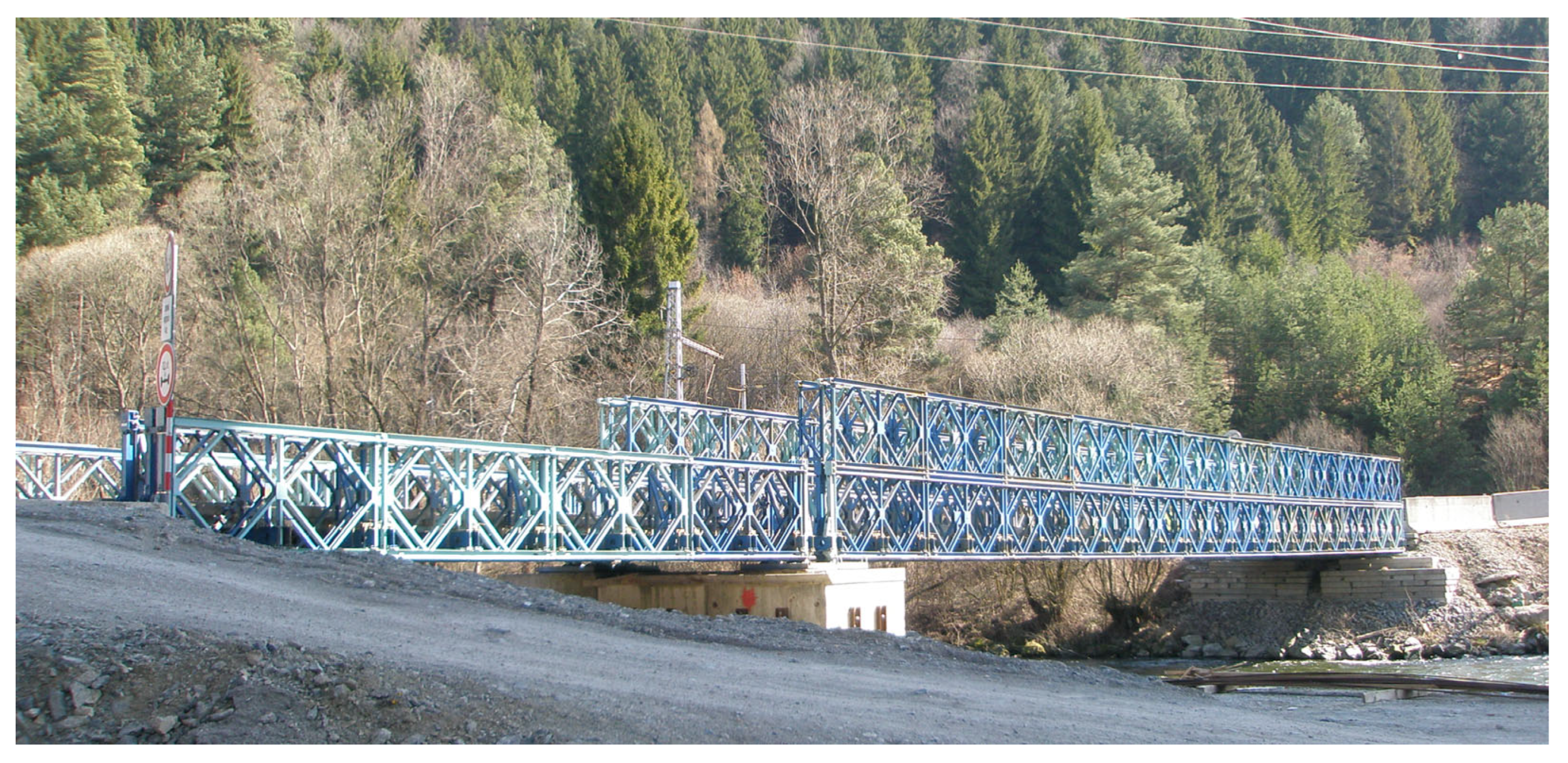
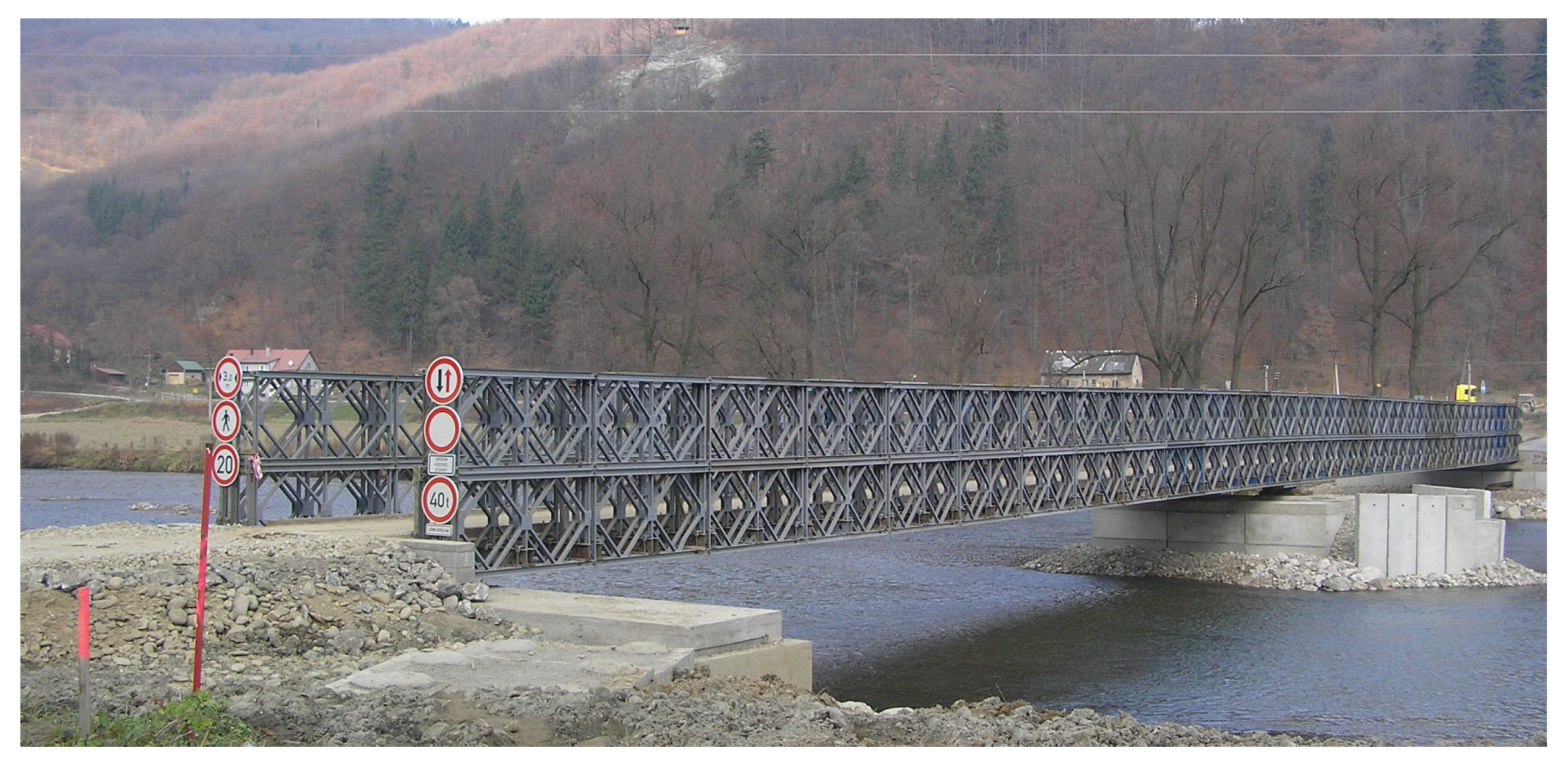
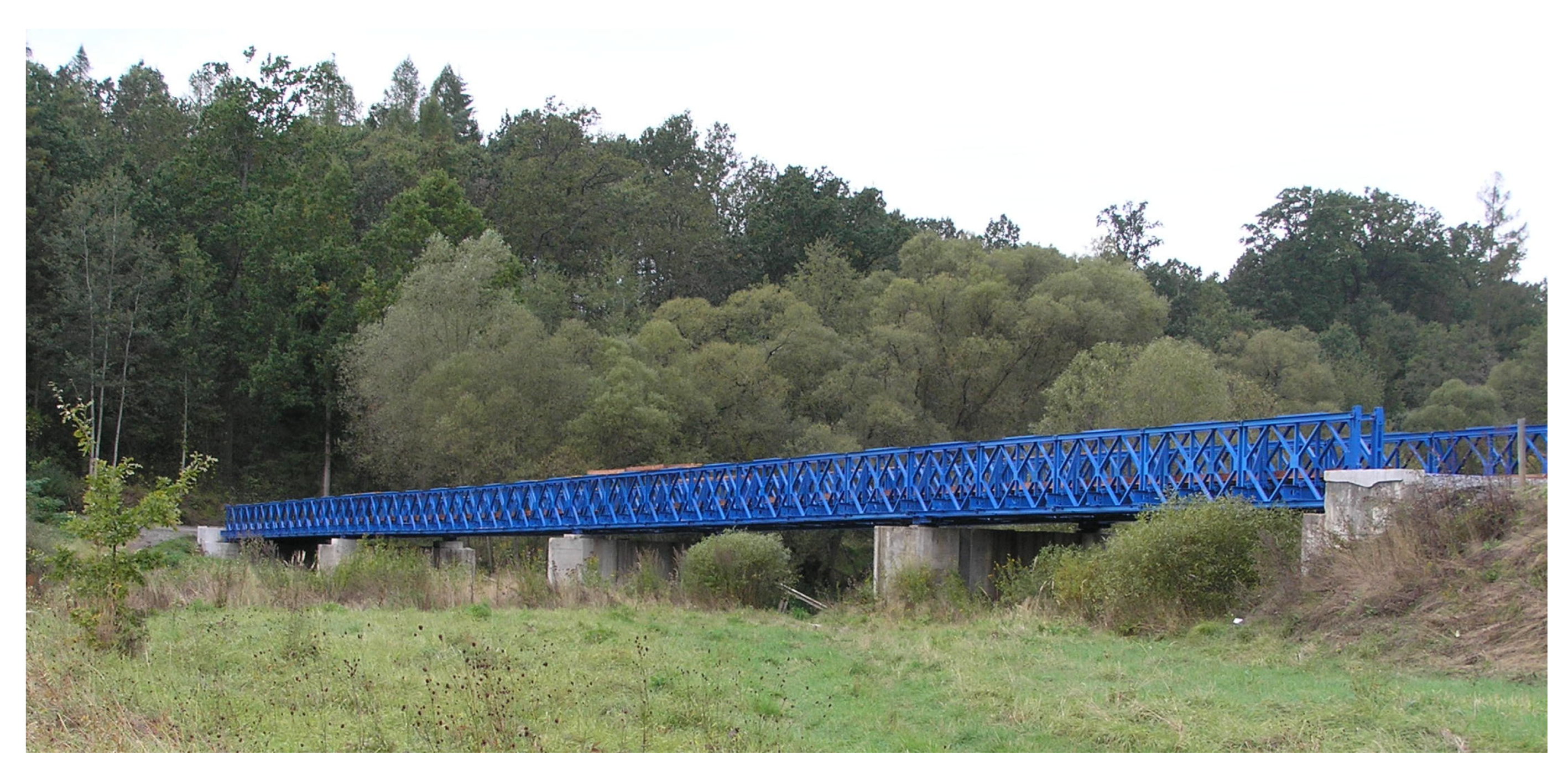
1. Introduction
2. Outline of the Study
- Double-truss, single-story (DS) for a span with length of 12.196 m;
- Triple-truss, single-story (TS) for spans: 12.192 m, 15.240 m, 18.288 m and 21.336 m;
- Double-truss, double-story (DD) for spans: 21.336 m, 24.384 m and 27.432 m;
- Triple-truss, double-story (TD) for spans: 27.432 m, 30.480 m, 33.528 m, and 36.576 m.
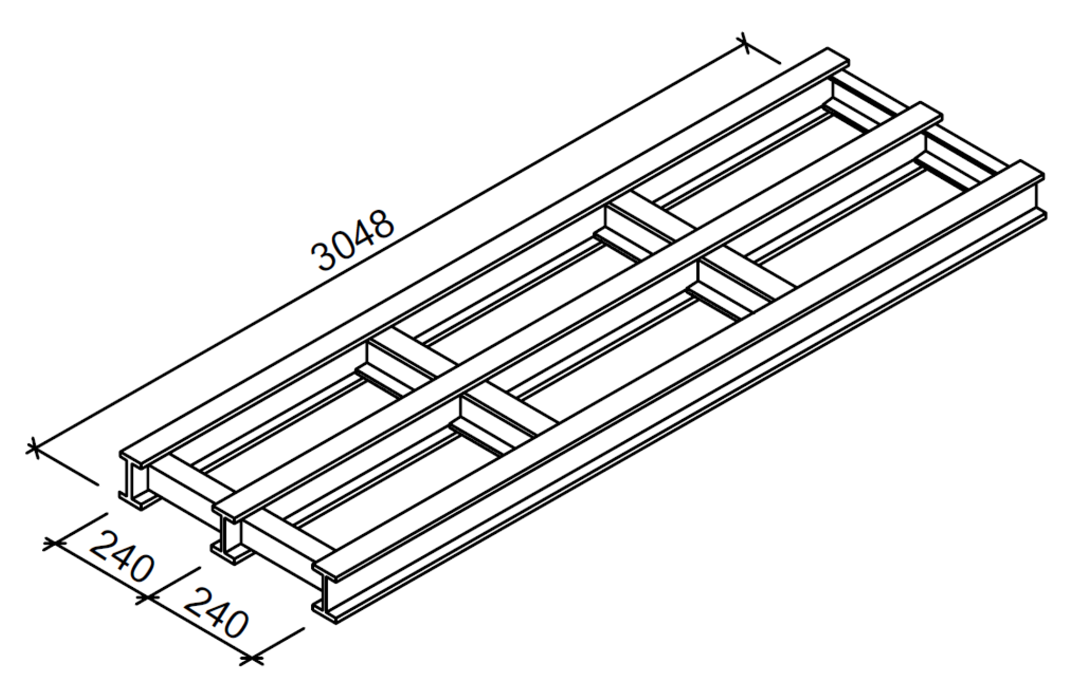
- Stringers (Figure 4)
- -
- Old stringers made of the original cross-section.
- -
- New stringers made of the cross-section IPN100.
- -
- Alternative new stringers made of the cross-section IPN120.
- Cross beams—‘transoms’.
- Panel of truss girders.
- -
- Upper chord.
- -
- Bottom chord.
- -
- Diagonals with U-shaped cross-section.
- -
- Alternative diagonals with I-shaped cross-section.
- -
- Verticals with U-shaped cross-section.
- -
- Alternative verticals with I-shaped cross-section.
- End verticals—‘end posts’.
- Inclined struts—‘rakers’.
- Panel pin (hinged connection between panels).
- Bottom bracings—‘sway brace’.
- Floor bolts (in double-storeys arrangement)—‘chord bolts’.
- a)
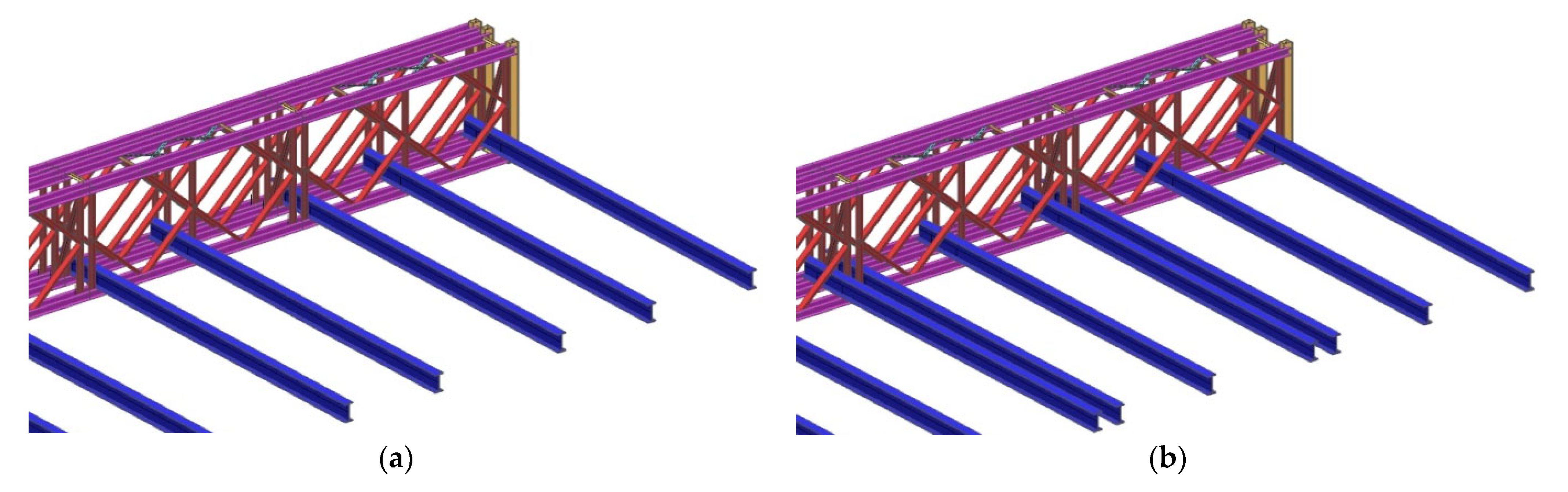
- Three cross beams within each panel of the bridge—the spans of the stringers are then 1440 + 1290 + 318 mm.
- b)
- Two cross beams within each panel of the bridge—the spans of the stringers are then 1608 + 1440 mm (this alternative was applicable only for single-story systems).
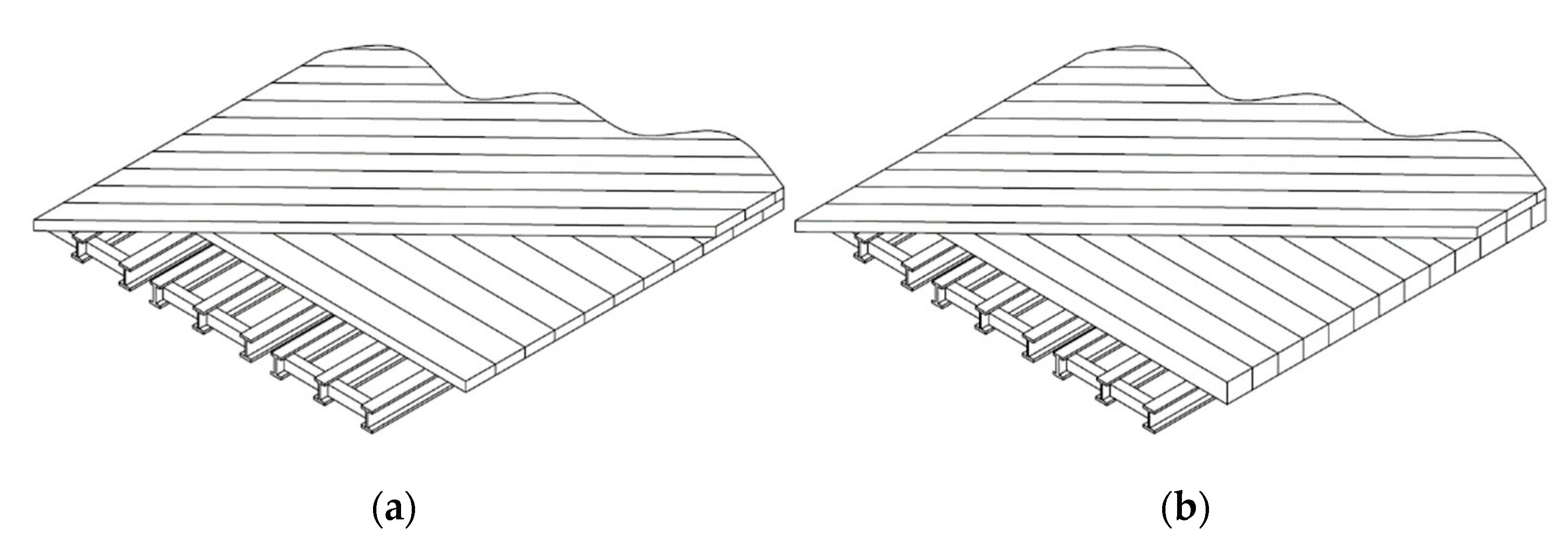
- a)
- Standard solution of two layers of 2 × 50 mm thick timber boards, where the bottom boards are placed perpendicular to the stringers, while the top layer is oriented in 45° degrees to the bridge axis;
- b)
- Stiffer roadway, where bottom supporting layer of the bridge deck is made of timber beams of 100 mm section height placed side by side perpendicular to the stringers, while the top layer stays the same as in the alternative a).
3. Global Analyses
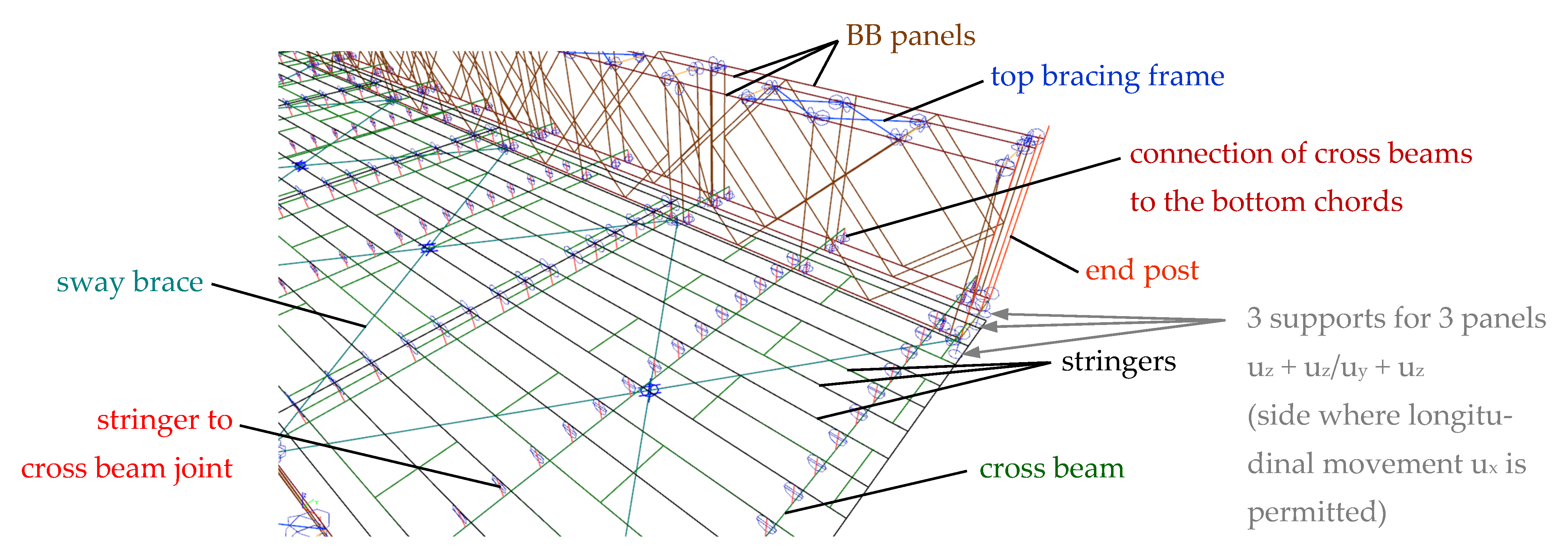
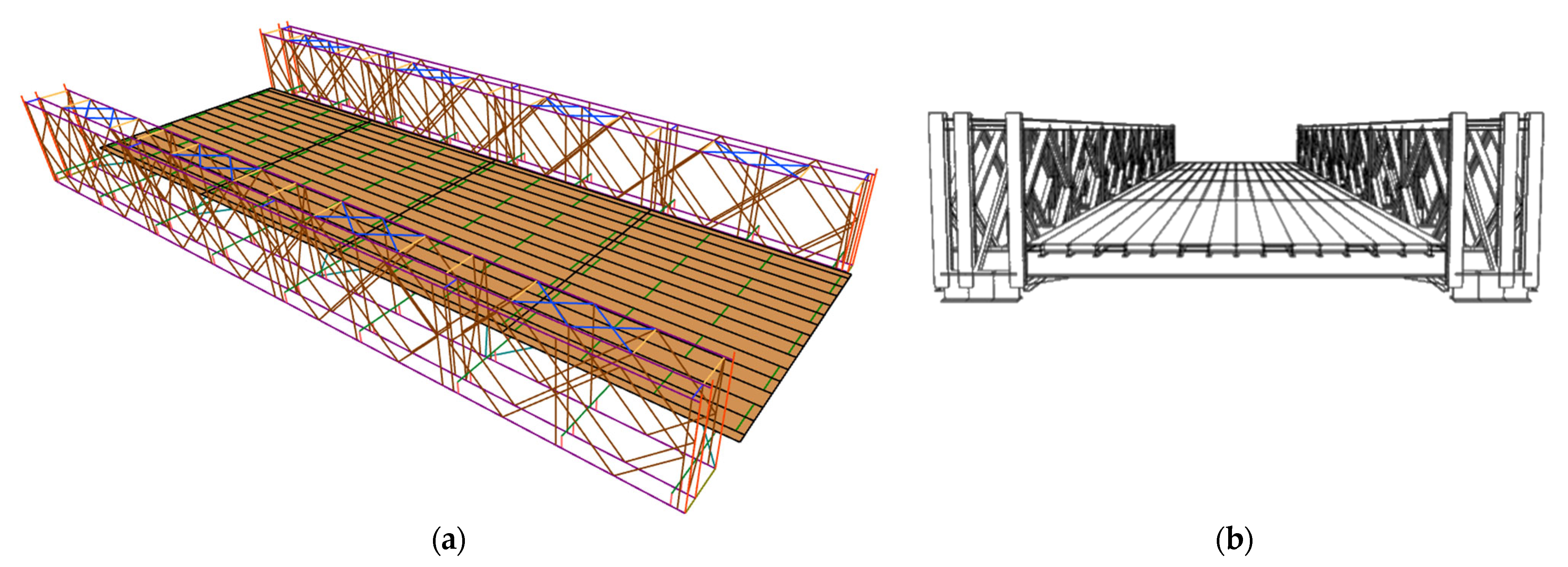
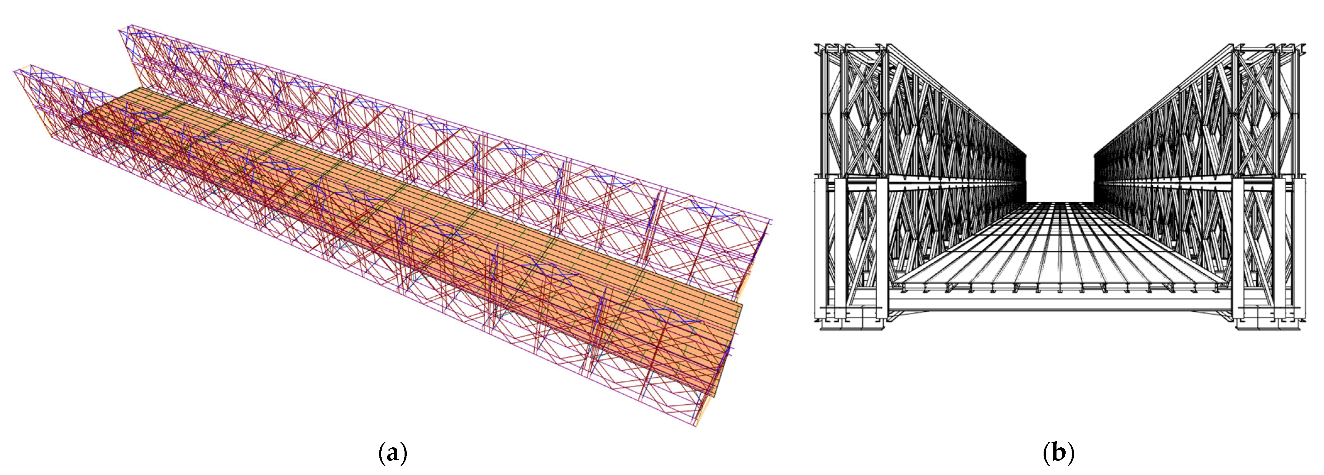
3.1. Numerical Models
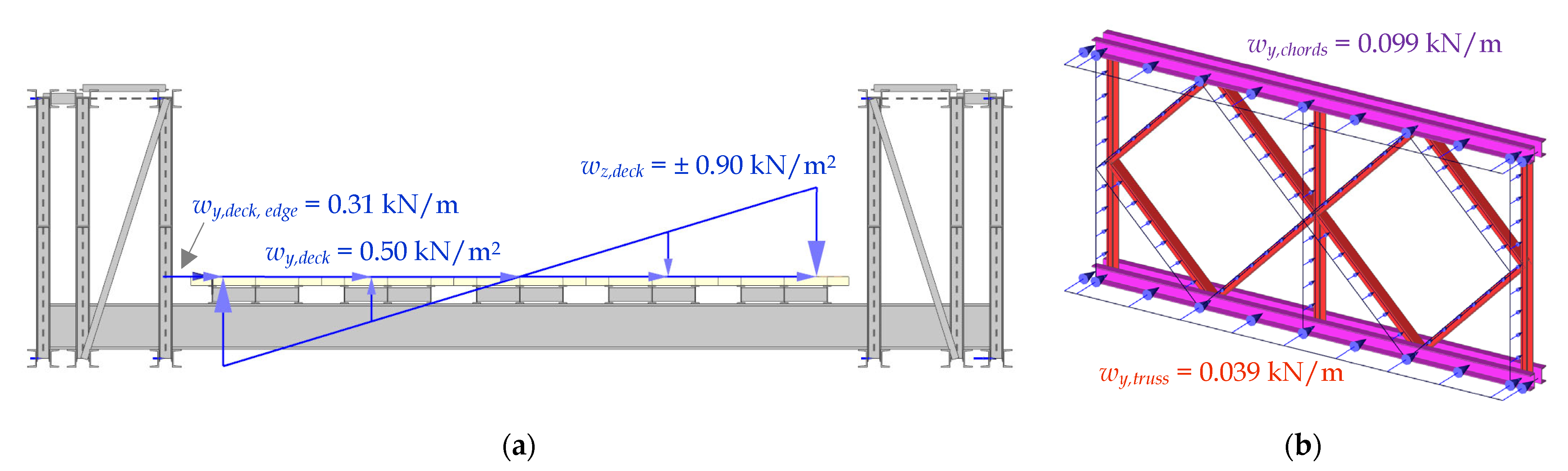
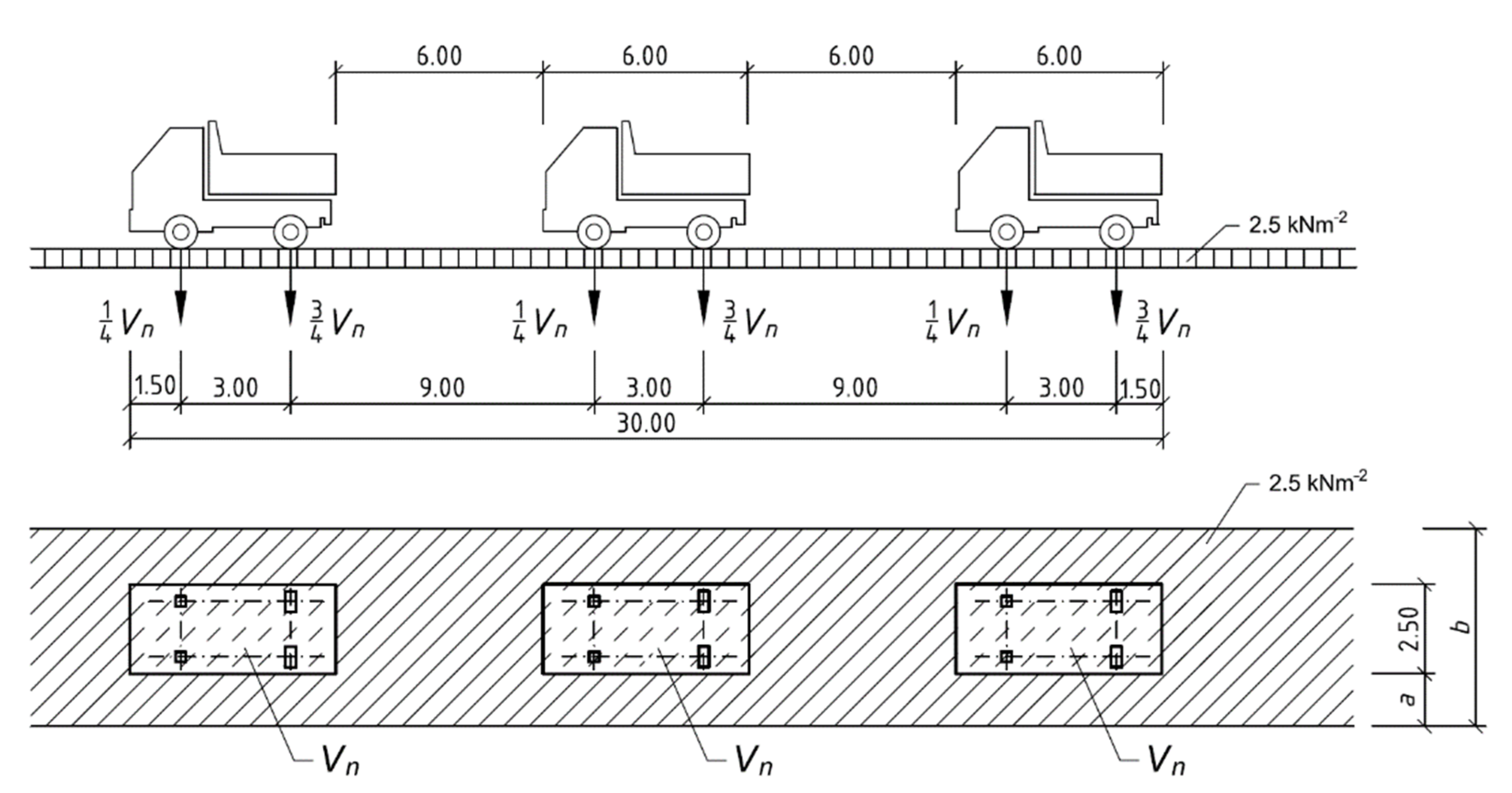
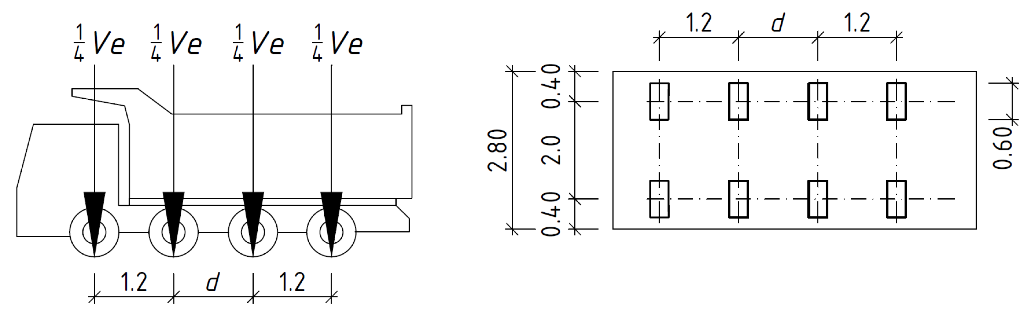
3.2. Loads in Global Analysis
3.3. Stability Analysis
4. Load-Carrying Capacity
5. Results and Discussion
5.1. Main Girders
5.2. Deck Members
5.2.1. Stringers
5.2.2. Cross Beams
6. Conclusions
Author Contributions
Funding
Institutional Review Board Statement
Informed Consent Statement
Data Availability Statement
Conflicts of Interest
References
- Benda, M.; Manas, P. Temporary Bridges Used in the Czech Republic. In Proceedings of the International Conference on Military Technologies (ICMT), Brno, Czech Republic, 31 May–2 June 2017; pp. 252–256. [Google Scholar]
- Ingham, B. Temporary bridging: Principles of design and construction. In Temporary Works, 2nd ed.; Pallett, P.F., Filip, R., Eds.; Ice Publishing: London, UK, 2018; Chapter 19; pp. 251–262. [Google Scholar]
- Field Manual: Bailey Bridge; FM 5-277; Headquarters Department of the Army: Washington, DC, USA, 1986; Available online: http://www.bits.de/NRANEU/others/amd-us-archive/fm5-277%2886%29.pdf (accessed on 20 February 2022).
- Jackson, G.B. The Bailey Bridge; New Zealand Engineering: Wellington, New Zealand, 1949; p. 1003. [Google Scholar]
- Roberts, L.D. The Bailey: The Amazing, All-Purpose Bridge. In Builders and Fighters: U.S. Army Engineers in World War II, 1st ed.; Fowle, B.W., Ed.; United States Army Corps of Engineers: Fort Belvoir, VA, USA, 1992; pp. 181–193. [Google Scholar]
- Bujňák, J.; Vičan, J.; Odrobiňák, J. Proof Load Tests and FEM Model as a Tools for Verification of Real Bridge Behaviour. In Proceedings of the 8th International Conference on Short & Medium Span Bridges, Niagara Falls, ON, Canada, 3–6 August 2010; p. 148/1-10. [Google Scholar]
- STANAG 2021; Military Load Classification of Bridges, Ferries, Rafts and Vehicles. NATO: Brussels, Belgium, 2017.
- Yi, P.; Vaghela, G.; Buckland, A. Condition Assessment and Load Rating of Arced Bailey Bridge. In Proceedings of the 9th Austroads Bridge Conference, Sydney, NSW, Australia, 22–24 October 2014; ARRB: Port Melbourne, Australia, 2014. [Google Scholar]
- Khounsida, T.; Nishikawa, T.; Nakamura, S.; Okumatsu, T.; Thepvongsa, K. Study on Static and Dynamic Behavior of Bailey Bridge. In Proceedings of the 2019 World Congress on Advances in Structural Engineering and Mechanics (ASEM19), Jeju Island, Korea, 17–21 September 2019; 12p. [Google Scholar]
- Lee, J.W.; Yoo, S.H.; Kim, I.S.; Kim, T.Y.; Choi, H.H.; Yoon, W.S.; Kim, Y.C. A study on the Analysis for the Strength of Bailey Panel Bridge. J. Korea Inst. Mil. Sci. Technol. 2011, 14, 15–21. [Google Scholar] [CrossRef]
- SCIA Engineer. Reference Guide; Nemetschek Group: Hasselt, Belgium, 2013. [Google Scholar]
- Jindra, D.; Kala, Z.; Kala, J. A comparison of FE Analysis of Columns Utilizing Two Stress-strain Material Relations and Two Different Solvers: ANSYS vs SCIA Engineer. In Proceedings of the International Conference on Computational Plasticity, Barcelona, Spain, 7–9 September 2021; 9 September 2021. [Google Scholar]
- Odrobiňák, J.; Farbák, M.; Chromčák, J.; Kortiš, J.; Gocál, J. Real Geometrical Imperfection of Bow-String Arches—Measurement and Global Analysis. Appl. Sci. 2020, 10, 4530. [Google Scholar] [CrossRef]
- Parivallal, S.; Narayanan, T.; Ravisankar, K.; Kesavan, K.; Maji, S. Instrumentation and Response Measurement of a Double-Lane Bailey Bridge During Load Test. Strain 2005, 41, 25–30. [Google Scholar] [CrossRef]
- Chen, W.Z.; Yan, B.C.; Liu, X.; Jiang, Y.D. Research on the Finite Element Simulation of and Updating Method for Old Riveted Truss Bridges. Stahlbau 2012, 81, 419–425. [Google Scholar] [CrossRef]
- EN 1993-1-1; Eurocode 3: Design of Steel Structures—Part 1-1: General Rules and Rules for Buildings. CEN: Brussels, Belgium, 2005.
- EN 1991-4; Eurocode 1: Actions on Structures—Part 1-4: General Actions—Wind Actions. CEN: Brussels, Belgium, 2005.
- Leahy, C.; OBrien, E.; O’Connor, A. The Effect of Traffic Growth on Characteristic Bridge Load Effects. Transp. Res. Procedia 2016, 14, 3990–3999. [Google Scholar] [CrossRef][Green Version]
- EN 1991-2; Eurocode 1: Actions on Structures—Part 2: Traffic Loads on Bridges. CEN: Brussels, Belgium, 2006.
- Vičan, J.; Odrobiňák, J.; Gocál, J. Determination of Road Bridge Load-Carrying Capacity. Civ. Environ. Eng. 2021, 17, 286–297. [Google Scholar] [CrossRef]
- Gocál, J.; Odrobiňák, J.; Vičan, J. On the Load-Carrying Capacity Produced by Different Load Models for Road Bridges. IOP Conf. Ser. MSE Civ. Eng. Conf. Košice, 2022; 10, accepted, in press. [Google Scholar]
- Skokandić, D.; Ivanković, A.M.; Znidarić, A.; Srbić, M. Modelling of traffic load effects in the assessment of existing road bridges. Gradevinar 2019, 71, 1153–1165. [Google Scholar]
- Kamruzzaman, M.; Haque, M.R. Assessment of Dead Load Deflection of Bailey Bridge. In Proceedings of the IABSE-JSCE Joint Conference on Advances in Bridge Engineering-IV, Dhaka, Bangladesh, 26–27 August 2020; pp. 306–310. [Google Scholar]
- Kaushik, H.B.; Talukdar, S. Structural Assasment of a Collapsed Bailey Bridge over Tuirini River on NH-150 in Aizawl, Miroram. Report Submitted to Deputy Commissioner, Aizawl, Mizoram. 2018. Available online: https://pwd.mizoram.gov.in/uploads/attachments/0b3455e113ace8c59ea54cc252dbf032/posts-67-structural-assessment-of-collapsed-bailey-bridge-over-tuirini-river1.pdf (accessed on 20 February 2022).
- King, W.S.; Duan, L. Experimental Investigations of Bailey Bridges. J. Bridge Eng. 2003, 8, 334–339. [Google Scholar] [CrossRef]
- Kala, Z.; Seitl, S.; Krejsa, M.; Omishore, A. Reliability Assessment of Steel Bridges Based on Experimental Research. In Proceedings of the International Conference on Numerical Analysis and Applied Mathematics (ICNAAM), Rhodes, Greece, 13–18 September2018. published 2019. [Google Scholar]
- EN 1993-2; Eurocode 3: Design of Steel Structures—Part 2: Steel Bridges. CEN: Brussels, Belgium, 2006.
- King, W.S.; Wu, S.M.; Duan, L. Laboratory Load Tests and Analysis of Bailey Bridge Segments. J. Bridge Eng. 2013, 18, 957–968. [Google Scholar] [CrossRef]
- Paeglitis, A.; Paeglitis, A. Simple Classification Method for the Bridge Capacity Rating. Constr. Sci. Sci. J. Riga Tech. Univ. 2010, 11, 44–50. [Google Scholar]
- Vičan, J.; Gocál, J.; Odrobiňák, J.; Koteš, P. Existing steel railway bridges evaluation. Civ. Environ. Eng. 2016, 12, 103–110. [Google Scholar] [CrossRef]
- UIC 70778-2; Recommendations for Determining the Carrying Capacity and Fatigue Risks of Existing Metallic Railway Bridges Aft. International Union of Railway: Paris, France, 2021; 77p.
- Railways of the Slovak Republic. General Technical Requirements: Determination of Load Carrying Capacity of Railway Bridges; Railways of the Slovak Republic: Bratislava, Slovakia, 2015; 116p. (In Slovak) [Google Scholar]
- Regulation SŽ S5/1; Diagnostics, Load-Carrying Capacity and Pass Ability of Railway Bridges. Czech Railway Administration: Prague, Czech Republic, 2021; 156p. (In Czech)
- Koteš, P.; Vičan, J. Recommended Reliability Levels for the Evaluation of Existing Bridges According to Eurocodes. Struct. Eng. Int. 2013, 23, 411–417. [Google Scholar] [CrossRef]
- Odrobiňák, J.; Hlinka, R. Degradation of Steel Footbridges with Neglected Inspection and Maintenance. Procedia Eng. 2016, 156, 304–311. [Google Scholar] [CrossRef]
- Gocál, J.; Odrobiňák, J. On the Influence of Corrosion on the Load-Carrying Capacity of Old Riveted Bridges. Materials 2020, 13, 717. [Google Scholar] [CrossRef] [PubMed]
- Macho, M.; Ryjacek, P.; Matos, J. Fatigue Life Analysis of Steel Riveted Rail Bridges Affected by Corrosion. Struct. Eng. Int. 2019, 29, 551–562. [Google Scholar] [CrossRef]


| Span | Truss | Story | Abbreviation |
|---|---|---|---|
| 40 ft/12.192 m | triple | single | TS-12 |
| 60 ft/18.288 m | triple | single | TS-18 |
| 70 ft/21.336 m | triple | single | TS-21 |
| 80 ft/24.384 m | double | double | DD-24 |
| 90 ft/27.432 m | double | double | DD-27 |
| 110 ft/33.528 m | triple | double | TD-33 |
| 120 ft/36.576 m | triple | double | TD-36 |
| Traffic Load in Combinations | Vn | Ve | ||||
|---|---|---|---|---|---|---|
| BB Arrangement | αcr,z [−] | Ncr,z [kN] | Lcr,z [m] | αcr,z [−] | Ncr,z [kN] | Lcr,z [m] |
| TS-12 | 7.53 | 4021 | 2.05 | 6.62 | 3743 | 2.12 |
| TS-18 | 5.73 | 3182 | 2.30 | 5.65 | 3128 | 2.32 |
| TS-21 | 4.79 | 2741 | 2.48 | 5.27 | 2967 | 2.38 |
| DD-24 | 4.93 | 2925 | 2.40 | 5.22 | 3149 | 2.32 |
| DD-27 | 4.83 | 2936 | 2.40 | 5.13 | 3088 | 2.34 |
| TD-33 | 4.47 | 2695 | 2.50 | 4.90 | 2952 | 2.39 |
| TD-36 | 4.38 | 2661 | 2.52 | 4.84 | 2928 | 2.40 |
| Normal Load-Carrying Capacity [tons] | Configuration | TS-12 | TS-18 | TS-21 | DD-24 | DD-27 | TD-33 | TD-36 |
|---|---|---|---|---|---|---|---|---|
| Span Length [m] | 12.192 | 18.288 | 21.336 | 24.384 | 27.432 | 33.528 | 36.576 | |
| Predominant Stress | Vn | Vn | Vn | Vn | Vn | Vn | Vn | |
| Chords | T + B (bottom) | 21.1 | 22.9 | 18.4 | 22.1 | 16.3 | 17.7 | 15.6 |
| C (top) | 54.8 | 38.0 | 30.0 | 41.2 | 30.9 | 27.5 | 20.4 | |
| Diagonals U | C | 22.6 | 19.8 | 18.6 | 23.0 | 21.5 | 22.3 | 21.3 |
| T | 39.1 | 42.1 | 40.1 | 44.0 | 42.4 | 43.5 | 42.7 | |
| Diagonals I | C | 18.9 | 16.5 | 15.4 | 19.0 | 17.7 | 18.4 | 17.7 |
| T | 45.8 | 45.0 | 43.0 | 47.1 | 45.2 | 46.7 | 45.6 | |
| Verticals U | C | 30.1 | 26.8 | 25.9 | 27.7 | 25.0 | 24.8 | 25.0 |
| T | 40.0 | 40.3 | 38.6 | 40.0 | 40.4 | 41.0 | 41.2 | |
| Verticals I | C | 25.4 | 22.4 | 21.7 | 22.7 | 20.1 | 20.6 | 19.9 |
| T | 42.3 | 42.5 | 42.2 | 43.6 | 44.1 | 44.6 | 44.9 | |
| Rakers | C | 31.3 | 34.3 | 31.3 | 37.2 | 37.2 | 40.7 | 43.5 |
| T | 92.6 | 91.4 | 67.3 | 95.2 | 79.4 | 83.6 | 80.0 | |
| End posts | C | 65.3 | 62.4 | 62.4 | 46.5 | 44.5 | 53.5 | 52.2 |
| Sway braces | T | 66.1 | 58.1 | 54.0 | 61.0 | 55.5 | 51.7 | 47.0 |
| Pin joint | S + B | 92.4 | 64.1 | 51.4 | 58.7 | 47.6 | 44.5 | 35.2 |
| Chord bolts | S + T | 66.7 | 61.8 | 63.7 | 60.9 |
| Exclusive Load-Carrying Capacity [tons] | Configuration | TS-12 | TS-18 | TS-21 | DD-24 | DD-27 | TD-33 | TD-36 |
|---|---|---|---|---|---|---|---|---|
| Span Length [m] | 12.192 | 18.288 | 21.336 | 24.384 | 27.432 | 33.528 | 36.576 | |
| Predominant Stress | Ve | Ve | Ve | Ve | Ve | Ve | Ve | |
| Chords | T + B (bottom) | 53.1 | 47.7 | 37.0 | 45.7 | 40.0 | 46.9 | 40.0 |
| C (top) | 76.2 | 50.6 | 42.0 | 59.8 | 51.4 | 55.2 | 47.8 | |
| Diagonals U | C | 33.2 | 34.1 | 33.4 | 46.5 | 45.9 | 47.4 | 47.0 |
| T | 56.9 | 64.0 | 60.8 | 78.5 | 78.2 | 81.2 | 80.9 | |
| Diagonals I | C | 28.9 | 29.9 | 29.3 | 40.5 | 39.8 | 41.1 | 40.6 |
| T | 64.6 | 66.7 | 65.3 | 82.4 | 82.2 | 85.2 | 85.0 | |
| Verticals U | C | 46.2 | 44.7 | 45.1 | 49.2 | 48.8 | 51.8 | 52.1 |
| T | 62.5 | 64.2 | 61.0 | 91.0 | 92.0 | 93.2 | 93.8 | |
| Verticals I | C | 40.6 | 39.0 | 38.9 | 41.9 | 41.5 | 45.2 | 44.6 |
| T | 73.2 | 75.3 | 71.3 | 98.1 | 99.1 | 100.4 | 101.1 | |
| Rakers | C | 42.1 | 30.7 | 30.7 | 51.2 | 51.3 | 51.8 | 56.2 |
| T | 106.2 | 99.0 | 87.7 | 129.5 | 125.6 | 152.8 | 148.0 | |
| End posts | C | 75.8 | 76.3 | 74.6 | 68.9 | 70.1 | 77.0 | 76.5 |
| Sway braces | T | 80.3 | 71.2 | 67.2 | 87.6 | 80.9 | 79.6 | 76.7 |
| Pin joint | S + B | 68.8 | 72.3 | 73.4 | 74.4 | 75.1 | 76.2 | 76.7 |
| Chord bolts | S + T | 113.2 | 109.8 | 115.4 | 114.1 |
| Stringers with Spans of 1608 + 1440 mm (2 Cross Beams within Each Panel) | |||||||
|---|---|---|---|---|---|---|---|
| Load-Carrying Capacity [tons] | Normal LCC Vn | Exclusive LCC Ve | Axle Weight | ||||
| Standard Deck | Stiffer Deck | Standard Deck | Stiffer Deck | Standard Deck | Stiffer Deck | ||
| original | mid-span | 10.0 | 11.9 | 31.7 | 38.1 | 7.5 | 8.9 |
| mid-support | 12.8 | 15.0 | 38.3 | 42.7 | 9.6 | 10.7 | |
| IPN100 | mid-span | 13.1 | 15.5 | 41.2 | 49.1 | 9.8 | 11.6 |
| mid-support | 16.9 | 19.9 | 49.7 | 55.9 | 12.4 | 14.0 | |
| IPN120 | mid-span | 20.8 | 24.4 | 64.3 | 76.2 | 15.6 | 18.3 |
| mid-support | 26.2 | 31.2 | 76.3 | 86.2 | 19.1 | 21.5 | |
| Stringers with Spans of 1440 + 1290 + 318 mm (3 Cross Beams within Each Panel) | |||||||
|---|---|---|---|---|---|---|---|
| Load-Carrying Capacity [tons] | Normal LCC Vn | Exclusive LCC Ve | Axle Weight | ||||
| Standard Deck | Stiffer Deck | Standard Deck | Stiffer Deck | Standard Deck | Stiffer Deck | ||
| original | mid-span | 12.6 | 12.4 | 37.2 | 38.4 | 9.3 | 9.3 |
| mid-support | 18.1 | 17.6 | 51.0 | 53.8 | 12.8 | 13.2 | |
| IPN100 | mid-span | 16.6 | 16.3 | 48.2 | 49.6 | 12.1 | 12.3 |
| mid-support | 24.6 | 24.2 | 66.7 | 63.0 | 16.7 | 15.8 | |
| IPN120 | mid-span | 26.5 | 26.2 | 75.3 | 77.6 | 18.8 | 19.4 |
| mid-support | 39.7 | 39.7 | 99.4 | 90.5 | 24.9 | 22.6 | |
| Three Cross Beams within Each Panel (Stringers with Spans of 1440 + 1290 + 318 mm) | ||||
|---|---|---|---|---|
| Load-Carrying Capacity [tons] | Normal LCC Vn | Exclusive LCC Ve | Axle Weight | |
| Cross beam | DS | 28.3 | 57.1 | 14.3 |
| TS | 29.8 | 56.1 | 14.0 | |
| DD | 28.2 | 56.7 | 14.2 | |
| TD | 28.9 | 55.6 | 13.9 | |
| Two Cross Beams within Each Panel (Stringers with Spans of 1608 and 1440 mm) | ||||
|---|---|---|---|---|
| Load-Carrying Capacity [tons] | Normal LCC Vn | Exclusive LCC Ve | Axle Weight | |
| Cross beam | DS | 21.5 | 40.0 | 10.0 |
| TS | 24.5 | 47.3 | 11.8 | |
Publisher’s Note: MDPI stays neutral with regard to jurisdictional claims in published maps and institutional affiliations. |
© 2022 by the authors. Licensee MDPI, Basel, Switzerland. This article is an open access article distributed under the terms and conditions of the Creative Commons Attribution (CC BY) license (https://creativecommons.org/licenses/by/4.0/).
Share and Cite
Prokop, J.; Odrobiňák, J.; Farbák, M.; Novotný, V. Load-Carrying Capacity of Bailey Bridge in Civil Applications. Appl. Sci. 2022, 12, 3788. https://doi.org/10.3390/app12083788
Prokop J, Odrobiňák J, Farbák M, Novotný V. Load-Carrying Capacity of Bailey Bridge in Civil Applications. Applied Sciences. 2022; 12(8):3788. https://doi.org/10.3390/app12083788
Chicago/Turabian StyleProkop, Jozef, Jaroslav Odrobiňák, Matúš Farbák, and Vladimír Novotný. 2022. "Load-Carrying Capacity of Bailey Bridge in Civil Applications" Applied Sciences 12, no. 8: 3788. https://doi.org/10.3390/app12083788
APA StyleProkop, J., Odrobiňák, J., Farbák, M., & Novotný, V. (2022). Load-Carrying Capacity of Bailey Bridge in Civil Applications. Applied Sciences, 12(8), 3788. https://doi.org/10.3390/app12083788