Abstract
In recent years, there has been an increasing demand to replace ancient structures. The removal of such structures also involves the removal of the existing piles that supported the structures, and the backfilling of the pulling-out holes that formed during the removal. However, there are no standard guidelines for the backfilling of pulling-out holes. At present, therefore, each owner or contractor must determine the material and the construction method to use for backfilling. This results in a difference between the mechanical properties of the original soil and those of the soil that has been backfilled, namely, the soil on which a newly built structure will be constructed. In this study, it was assumed that a new pile would be installed on a perforated soil (that is, the soil left after removing the existing piles) where the mechanical properties differ between the original soil and the backfilled soil. The behavior of the new pile, when installed on the boundary of a soil between two types of mechanical properties, was evaluated by a three-dimensional linear elastic analysis. When the new pile was installed at the boundary between the two types of soil with different mechanical properties, most of the new pile was inclined to the soil side where the N value was relatively small. However, the inclination of the new pile was able to be suppressed by increasing the distance from the boundary between the two types of soil.
1. Introduction
Many cities in Japan and Southeast Asia are located on soft soil, and thus, many of the structures built on this type of soil have piles. In recent years, there has been an increasing demand to replace ancient structures that were built during the period of high economic growth in Japan. The removal of such structures also involves the removal of the piles (the existing piles) that supported the structures, and the backfilling of the pulling-out holes formed during the removal.
In Japan, these existing piles are categorized as industrial waste and must be removed from the soil in a reliable manner. For the same reason, it is not appropriate to break or to leave the existing piles or any part of them in the soil. The main method for removing an existing pile, without crushing or leaving it in the soil, is to pull it out. However, when an existing pile is removed by pulling it out, a pulling-out hole is formed [,,,]. If this pulling-out hole is left hollow, settlement will occur in the surrounding soil. On the other hand, it has been reported in past research that the settlement in the surrounding soil can be suppressed by filling in the pulling-out hole. In other words, as the soil in which a pulling-out hole remains may deteriorate, the backfilling of the pulling-out hole is essential [,,].
However, there are no standard guidelines for the backfilling of pulling-out holes [,,,]. At present, therefore, each owner or contractor must determine the material and the construction method to use for backfilling. This results in a difference between the mechanical properties of the original soil and those of the soil that has been backfilled, namely, the soil on which a newly built structure will be constructed.
In this study, it is assumed that a new pile will be installed on a perforated soil, (that is, the soil left after removing the existing piles) where the mechanical properties differ between the original soil and the backfilled soil. More specifically, the behavior of a new pile, when installed on the boundary of a soil between two types of mechanical properties, is evaluated by a three-dimensional linear elastic analysis.
2. Removal by Pulling Out Existing Piles
2.1. Existing Piles
When rebuilding or demolishing superstructures, the existing piles are designated as industrial waste under the Waste Management and Public Cleansing Law in Japan, and they must be properly removed [,,,,,]. However, in the removal of an existing pile by the pulling-out method, the problem of all or part of the existing pile remaining in the soil during the pulling-out process has become apparent.
If the existing pile remains in the soil, the remaining piles will become obstacles in the soil, causing delays in the construction period of the new pile at the site and the inferior construction of this new pile. In other words, underground residue from an existing pile has a negative effect on the installation of a new pile. An existing pile remaining in the soil is often related to the method that is used to pull out the existing pile. It is possible that the existing pile will be destroyed in the pulling-out process and broken piles will be left in the soil. At the same time, there are many existing piles buried in an unhealthy state, as shown in Figure 1. In addition, depending on the type of existing pile, there are places along the pile structure that can easily become separated, which may cause partial or full existing piles to remain underground.
Figure 1.
Examples of existing pile buried in an unhealthy state.
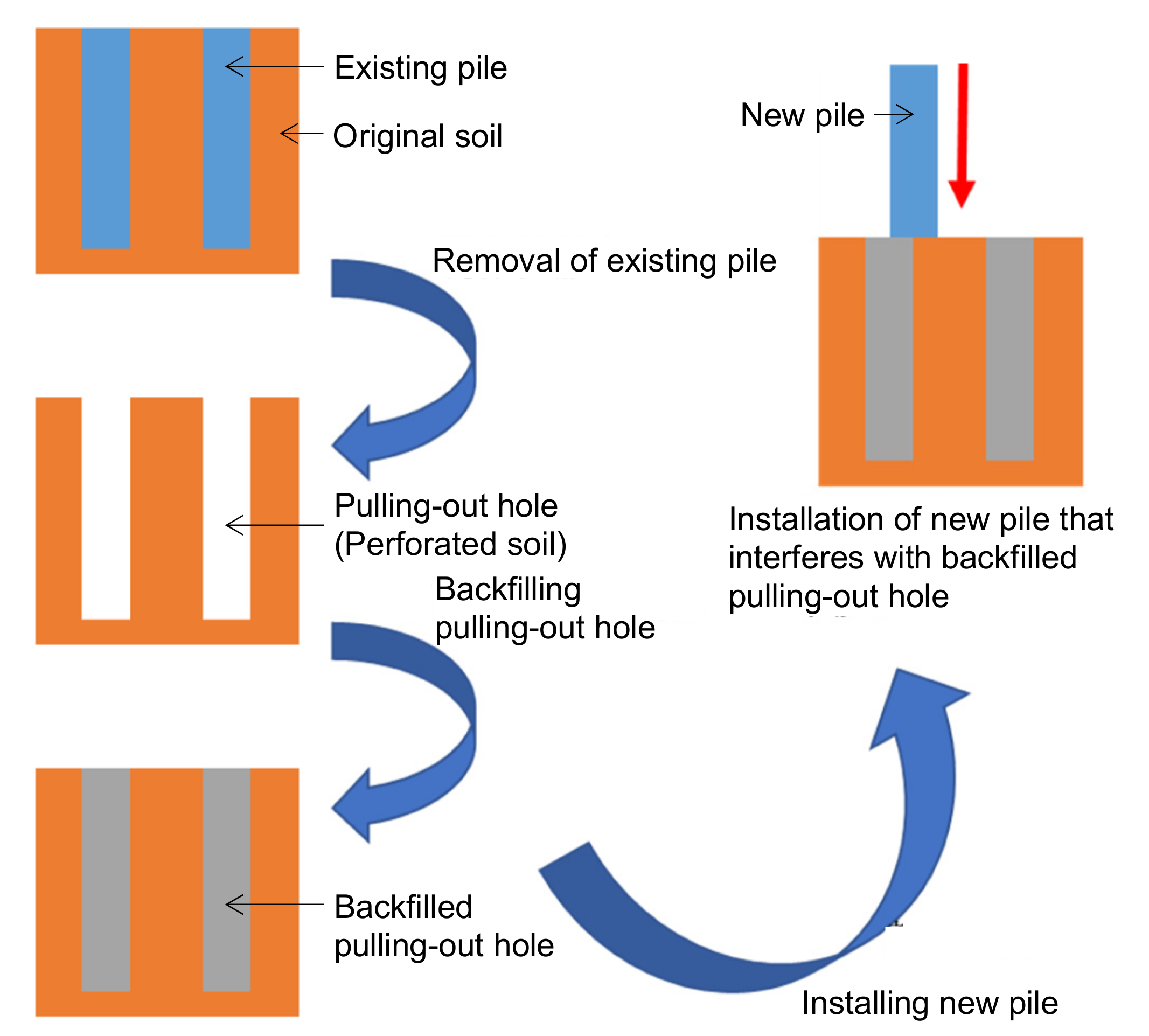
2.2. Soil Condition after Removal of the Existing Piles (Pulling-Out Holes)
When pulling out existing piles using the pulling-out method, it is essential to treat the pulling-out holes. If the pulling-out holes are not treated properly, they will create a negative soil impact, resulting in various problems. In order to treat the pulling-out holes, therefore, a backfilling treatment with a filler is performed []. The fillers used in the backfill treatment include sand, fluidized soil, cement milk, or equivalent [,,,,].
The backfill treatment with soil, such as sand, is advantageous in that the treatment is easy and inexpensive. However, because the rolling compaction works involved with this backfill treatment are difficult, uniform filling is also difficult, and stable strength cannot be secured. In addition, there are cases where settlement has occurred in the backfill treatment area approximately one month after the treatment due to backfilling with loose soil, such as sand, and where settlement and depression have occurred because of heavy rain.
Fluidized soil is a filler obtained by mixing soil, water, and a cement-based solidifying material [,,,,]. It is considered a recycled material when construction sludge is reused as the soil. As fluidized soil has high fluidity and self-hardening properties due to the cement-based solidification material, it can be filled into minute spaces and has the characteristic of exhibiting strength, even in spaces where compaction work is impossible. In addition, because fluidized soil has an impermeable property, it has the advantage of exhibiting stable strength against the infiltration of groundwater. However, fluidized soil must be brought in from an external facility; thus, its use is limited to sites which are located within a reasonable proximity. Moreover, it is difficult to cast this soil in accordance with the construction situation.
Poorly mixed cement milk is a filler that contains water, cement, and bentonite []. As cement milk has high fluidity and self-hardening properties, it can be filled into minute spaces and exhibits strength. In addition, quality control, such as strength, can be easily performed by controlling the water/cement ratio, and the kneading operation can be performed in an all-purpose plant facility. In general, however, poorly mixed cement milk may have uneven strength in the depth direction due to the separation of the water and the cement materials. Furthermore, it is possible that the strength may decrease to below the predetermined value due to the infiltration of groundwater, or that solidification failure may occur.
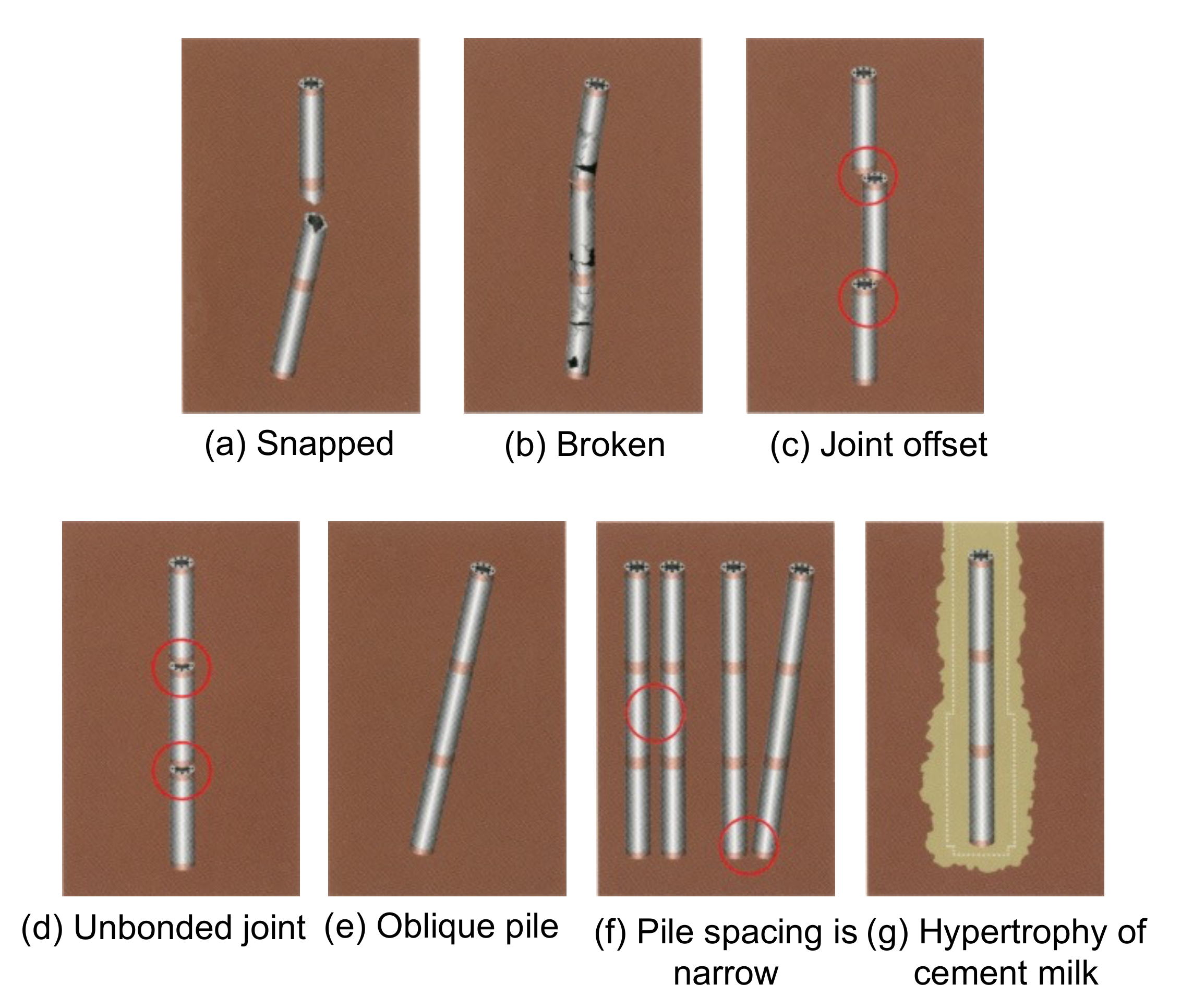
2.3. Removal of Existing Piles That Interfere with New Piles
In urban areas, the number of cases where new structures are constructed at almost the same locations as the old structures has been increasing. Therefore, the position where the pile (existing pile) of an old structure was installed and the position where the new pile will be installed may overlap [,,,,,]. In such a case, the existing pile is pulled out, the pulling-out hole is backfilled, and then the new pile is constructed at that location. As the mechanical characteristics of the backfilling-treated pulling-out hole are different from those of the surrounding soil, problems such as inclination and eccentricity may be encountered during the construction of the new pile.
Thus, although the existence of an existing pile and the method of its removal are the main causes of trouble in the construction of a new pile, no clear rules or guidelines on the method of removal and subsequent measures have been established. At present, each company is taking unique action. This issue is common to all pile construction methods; thus, it is desirable that an appropriate removal method be proposed and that the guidelines for it be quickly authorized [,,,,,].
Figure 2 shows the flow from the removal of an existing pile to the installation of a new pile at that location.
Figure 2.
Typical flow from removal of existing pile to installation of new pile at that location.
3. Analysis Target and Conditions
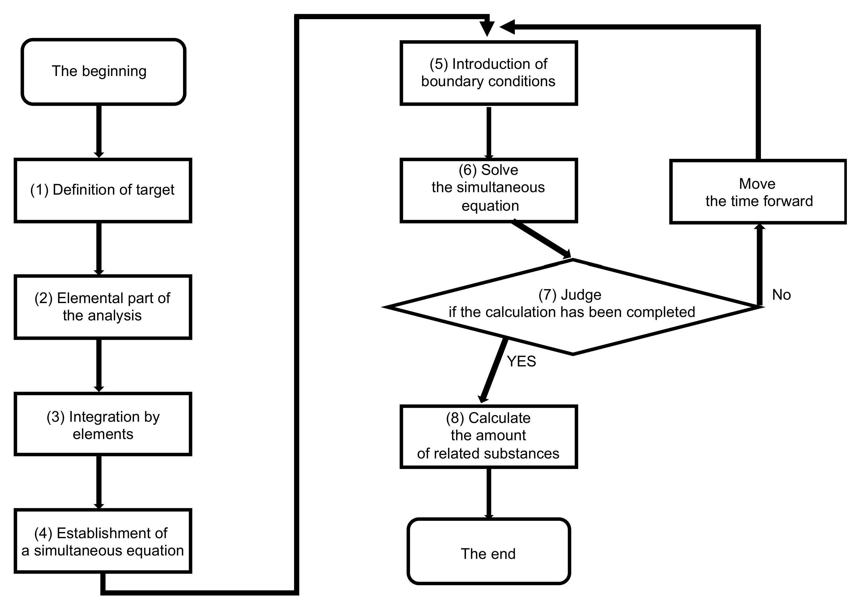
3.1. Linear Elasticity Analysis
In this study, a three-dimensional linear elasticity analysis is performed using MIDAS GTS NX [,]. The linear elasticity analysis is one of several deformation analyses performed on the soil using the finite element method. It is an analysis method that regards the soil as an elastic body. Elasticity refers to a spring-like property whereby, when an external force is applied to an object, proportional deformation occurs; when the external force is removed, the object returns to its original shape. An object with these properties is considered an elastic body.
Figure 3 shows the flowchart of the three-dimensional linear elasticity analysis using MIDAS GTS NX [,].
Figure 3.
Flowchart of three-dimensional linear elasticity analysis using MIDAS GTS NX.
3.2. Calculation Method for Elastic Modulus
In this study, the material parameters are set by calculating the elastic modulus from the N value [,,]. The calculation formula is shown in Equation (1) [,,,]. It should be noted that 1 kgf = 9.8 N.
E = 28 × (N value) [kgf/cm2]
The N value is a value obtained by a standard penetration test (SPT) [,,]. In the SPT, a 63.5 (±0.5) kg weight is dropped from a height of 76 (±1) cm, and the rod of the special sampler penetrates the soil. The number of hits (the number of times the weight must be dropped) required for the tip of the rod to penetrate 30 cm into the soil is measured. That value is the N value. In drilling for soil surveys, N values are usually measured at one meter intervals. The sample collected by the sampler is used for a particle size composition analysis and geological composition discrimination. Furthermore, the N value of the standard penetration test is incorporated into various standard systems and is treated as information essential for the design and construction of civil engineering and building structures.
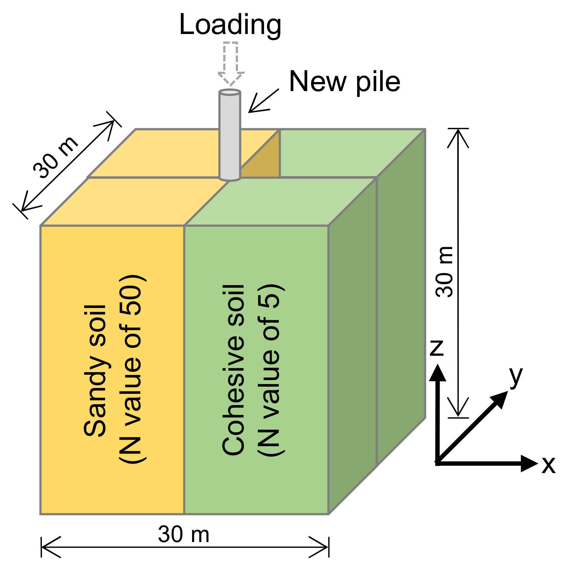
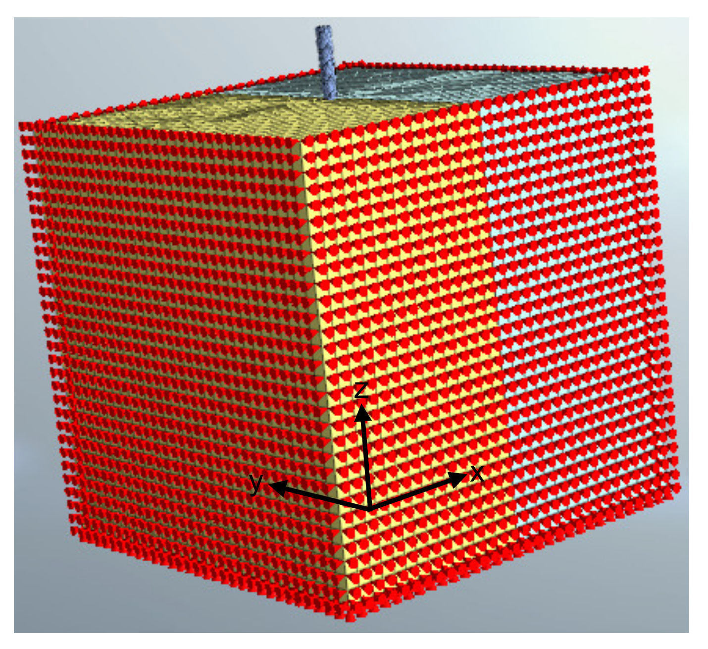
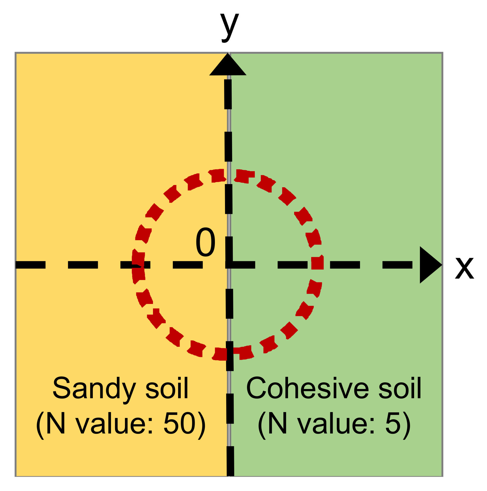
3.3. Analysis Target and Boundary Conditions
Figure 4 shows the analysis models applied in this study. A 30-m cube is used as the soil profile, and a cylinder that is one meter in diameter and 20 m in length is used to simulate the new piles. This cylinder (the new pile) that penetrates vertically into the cube (the soil) up to 15 m is the analysis model; it reproduces the situation where a new pile is installed on the perforated soil. The soil characteristics are changed by dividing the cube into two equal parts to represent the two types of soil with different mechanical characteristics after the removal of the existing piles, and a load is applied from the head of the cylinder. Table 1 shows the soil parameters, assuming sandy soil with an N value of 50, cohesive soil with an N value of five, and piles made of steel [,]. The elastic modulus, Poisson’s ratio, and wet volume mass were estimated from the N values. The boundary conditions, shown in Figure 5, restrict the displacement in the x-axis direction on the right, left, and bottom surfaces of the analysis model, and restrict the displacement in the y-axis direction on the front, rear, and bottom surfaces of the analysis model.
Figure 4.
Analysis models applied in this study.
Table 1.
Ground parameters set in the three-dimensional linear elastic analysis.
Figure 5.
Boundary conditions for displacement constraints in analysis model.
4. Analysis Results and Discussion
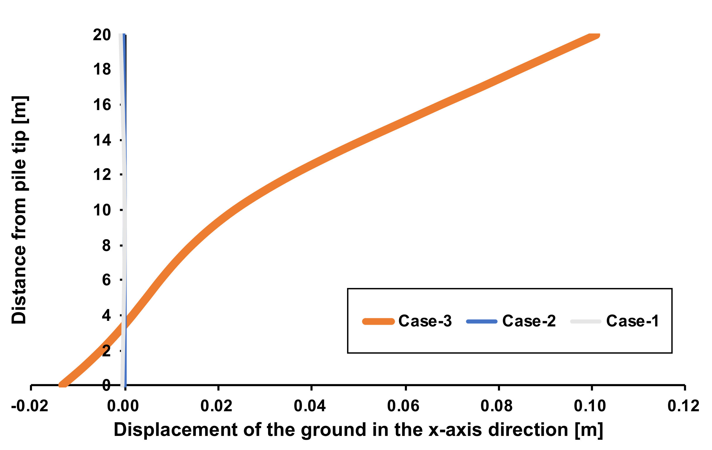
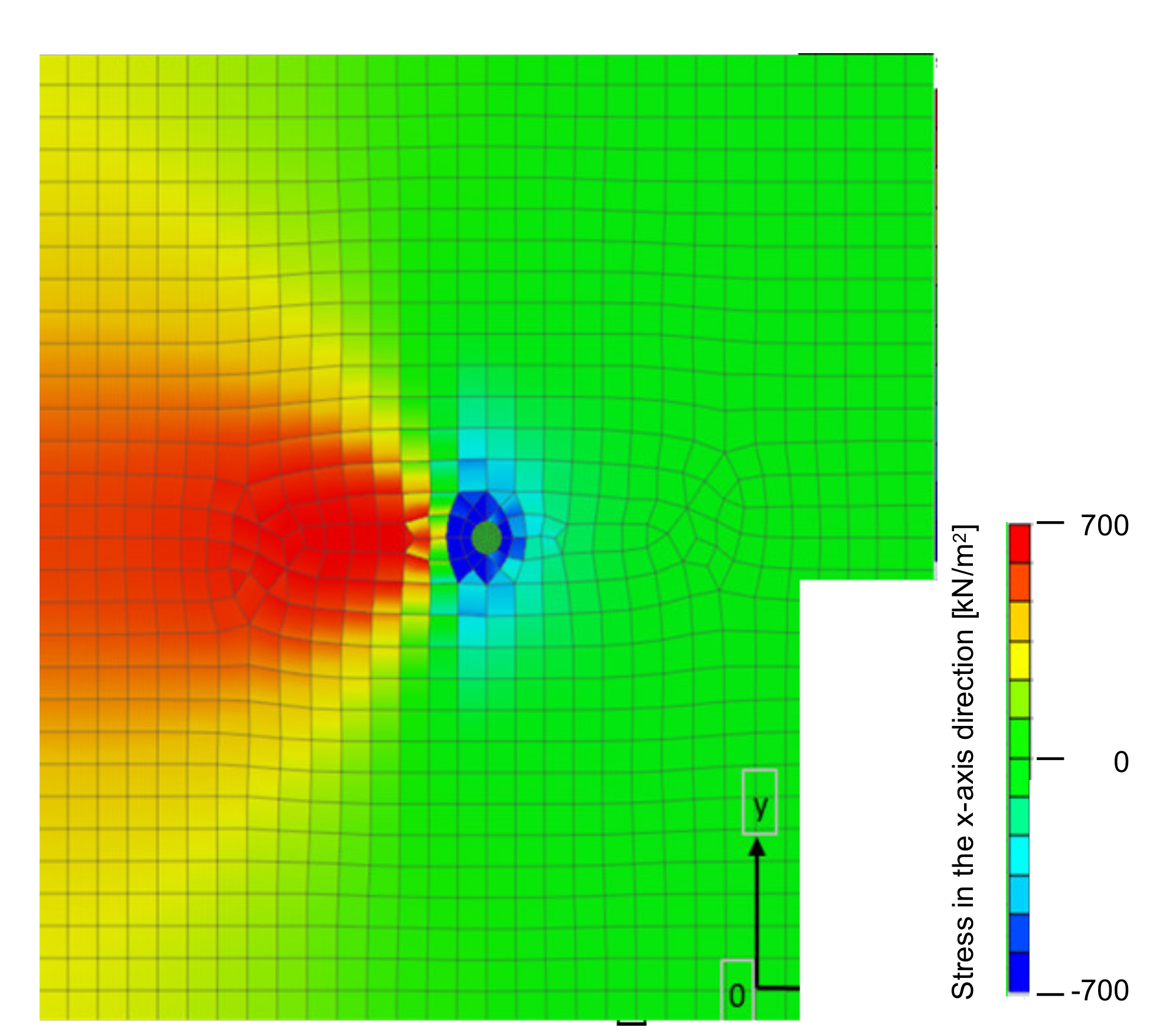
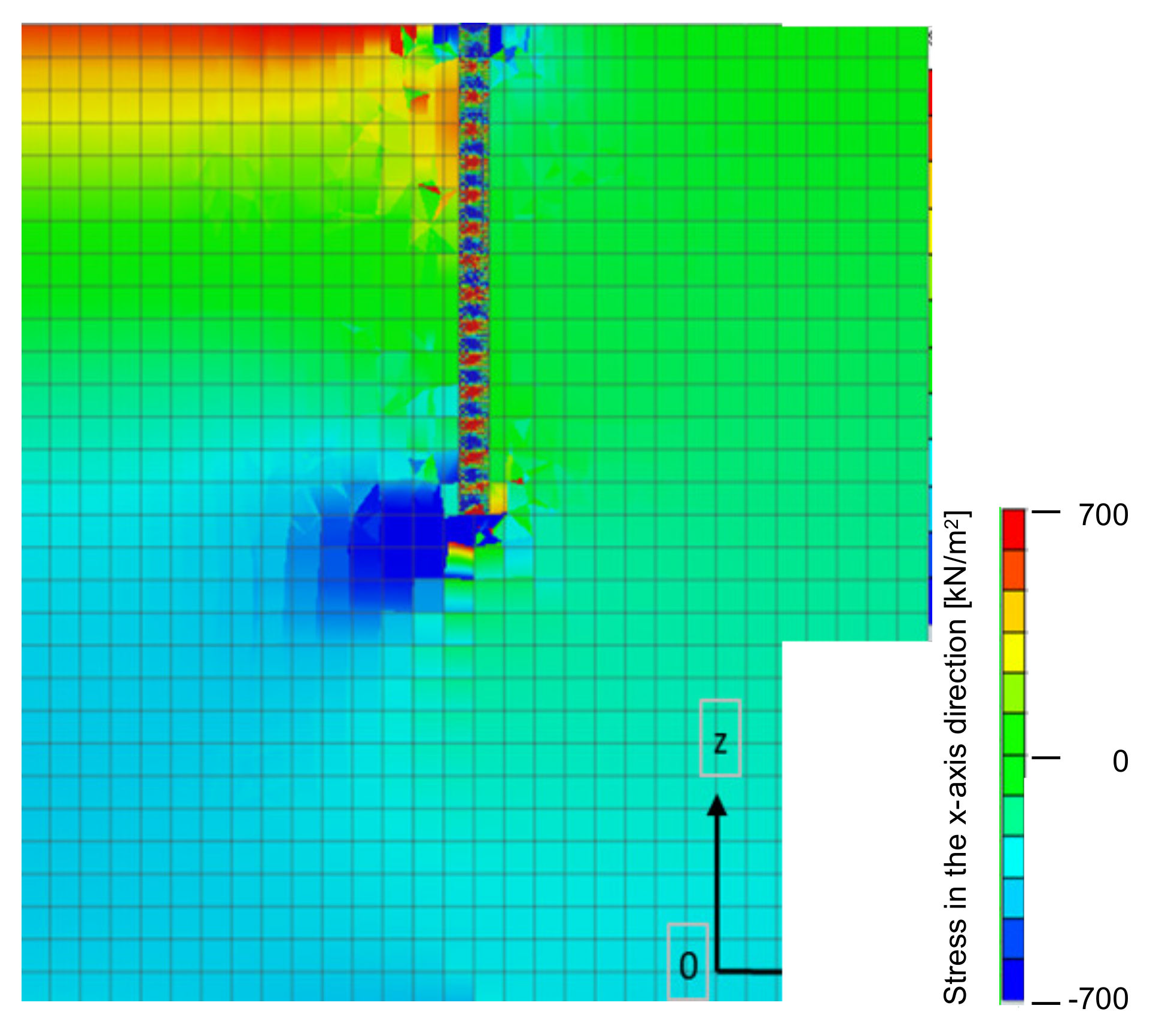
4.1. Influence of Soil with Difference in Mechanical Properties
The study assumes a soil with one (homogeneous) mechanical property and a soil boundary with two (heterogeneous) mechanical properties. During the installation of the new pile on that soil, the behavior of the new pile is verified. Here, in the homogeneous soil, two cases are assumed: a homogeneous soil with an N value of 50 (Case-1) and a homogeneous soil with an N value of five (Case-2). Furthermore, it is assumed that soils with N values of 50 and five are halved in the heterogeneous soil (Case-3). Figure 6 corresponds to Case-3 and shows the position where a new pile is installed at the boundary between two types of soil with different mechanical properties. For Case-1 and Case-2, there is no boundary between the two types of soil, but the new pile is installed at the same position as that of Case-3. The load acting on the pile head of the new pile is 200 N/mm2.
Figure 6.
Top view of installing position of newly built pile foundation.
Figure 7 compares the displacements of the soil in the x-axis direction in Case-1, Case-2, and Case-3. The new pile cast in Case-3 tends to lean toward the soil with an N value of five (positive x-axis direction) compared to Case-1 and Case-2. Focusing on the deformed shape of the new pile, it can be confirmed that the warp rises to the soil side (negative direction in the x-axis direction) with an N value of 50, approximately 10 m from the tip of the pile. Figure 8 shows the displacements in the x-axis direction as a result of Case-3. It also shows, for reference, the assumption that the new pile was installed straight, without deformation. Figure 9 and Figure 10 show the stress in the x-axis direction inside the soil. Figure 9 is a top view of the analysis model, and Figure 10 is a cross-section of the analysis model cut parallel to the x-axis. Most of the new pile is inclined toward an N value of five, that is, the soft soil side. On the soil surface, the stress acts in the negative direction in the x-axis only on the soil around the pile, while the stress inside the soil with an N value of 50 is working on the positive direction in the x-axis.
Figure 7.
Comparison of displacements of ground in x-axis direction in Case-1, Case-2, and Case-3.
Figure 8.
Displacements in x-axis direction as a result of Case-3, as well as when assuming that the new pile was installed straight, without deformation.
Figure 9.
Top view of stress distribution in x-axis direction inside ground for Case-3.
Figure 10.
Side view of stress distribution in x-axis direction inside ground for Case-3.
From the results obtained from Figure 7, Figure 8, Figure 9 and Figure 10, it is considered that the stress from the harder soil with an N value of 50 pushes the new pile on the soil surface near the new pile. In addition, it is thought that the stress generated in the warped state of the new pile will return to the original state (the non-warped state). Due to the above two factors, the stress acting on the soil surface around the new pile is assumed to act in the opposite direction to the direction in which the new pile is inclined.
The displacement in the y-axis direction of the new pile cast at the boundary between the two types of soil with different mechanical properties was 0.1 mm maximum. From this, it is thought that there is no inclination in the y-axis direction.
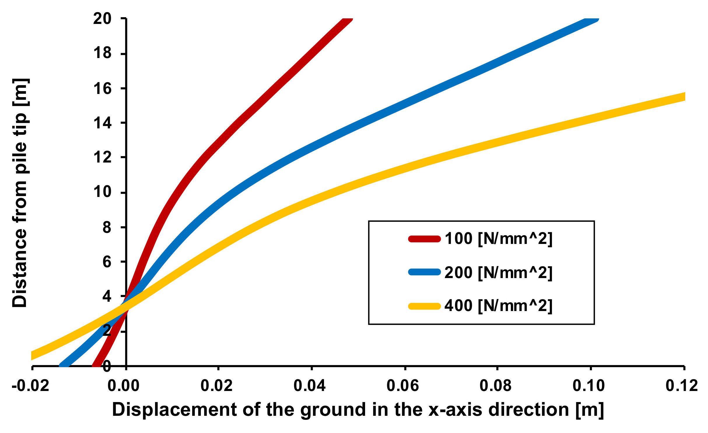
4.2. Load Acting on New Pile and Inclination of New Pile
The change in the displacement of the new pile in the x-axis direction is verified by changing the magnitude of the load acting on the pile head when placing the new pile.
Similar to Case-3, two types of soil with different mechanical properties exist, as shown in Figure 6. That is, there is a soil with an N value of 50 and a soil with an N value of five. The new pile is placed at the boundary between the two types of soil, namely, the center of the new pile, as shown by the origin in Figure 6. The loads acting on the pile head during the placing of the new pile are 100, 200, and 400 N/mm2.
Figure 11 shows the displacements in the x-axis direction when the loads acting on the pile head are 100, 200, and 400 N/mm2, respectively. Table 2 shows the relationship between acting loads on the new pile and their slopes. The inclination is calculated based on the displacements of the pile tip and the pile head, and the displacement of the soil surface position from the pile tip. As the load acting on the new pile increases, the inclination of the new pile increases. As the load acting on the new pile decreases, the inclination of the new pile decreases.
Figure 11.
Comparison of displacements in x-axis direction when loads acting on pile head are 100, 200, and 400 N/mm2, respectively.
Table 2.
Relationship between acting loads on newly built pile foundation and their slopes.
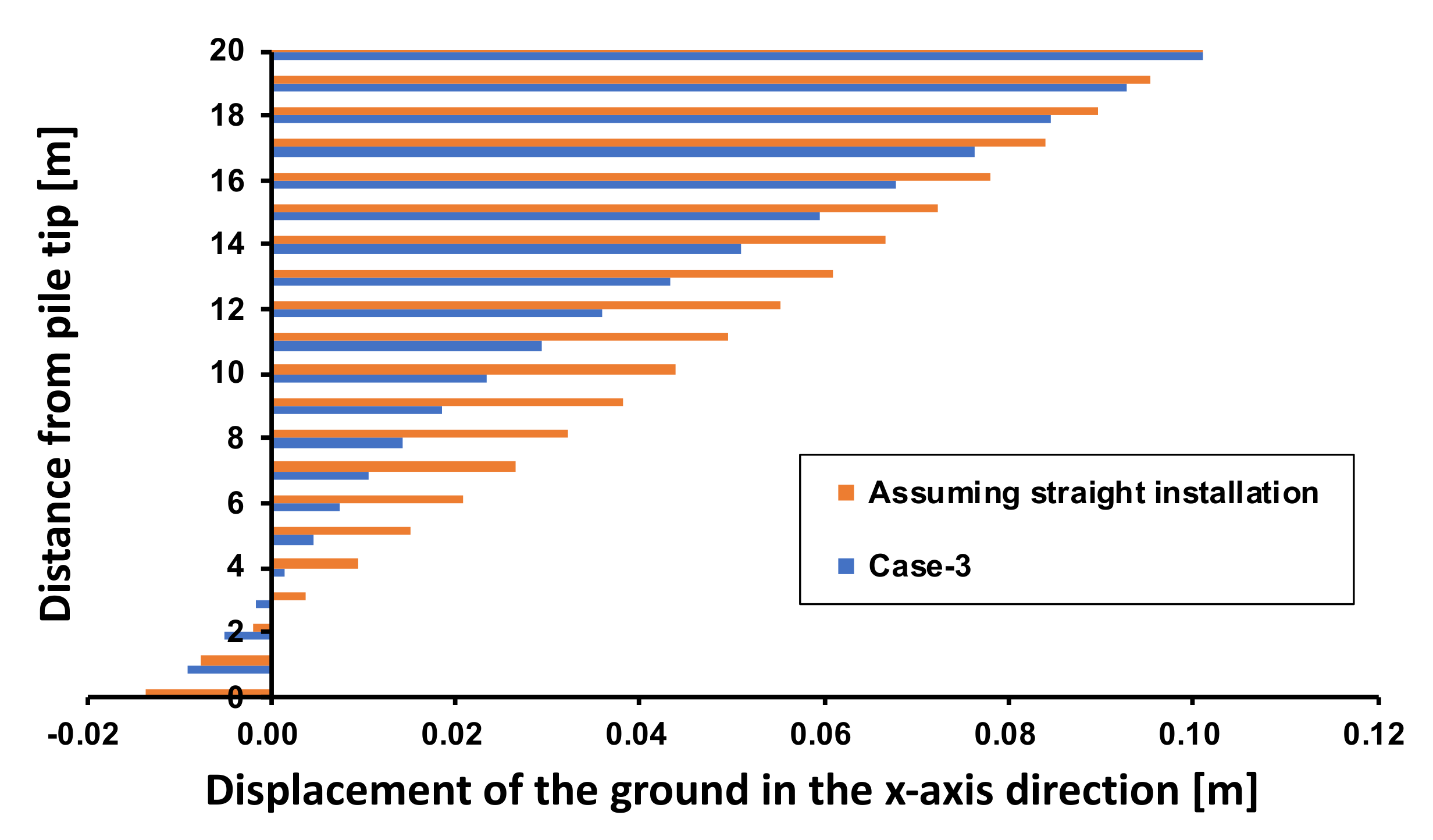
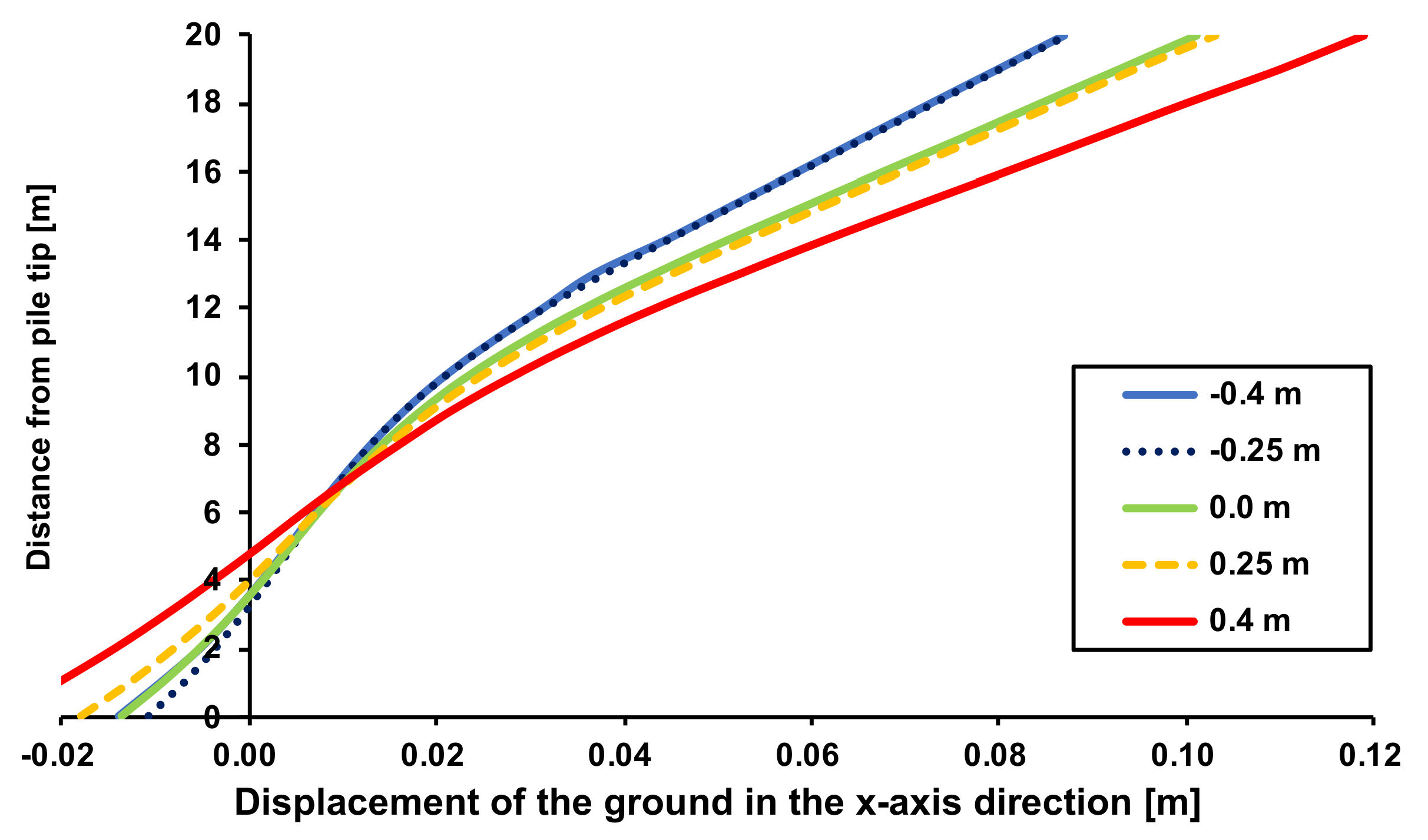
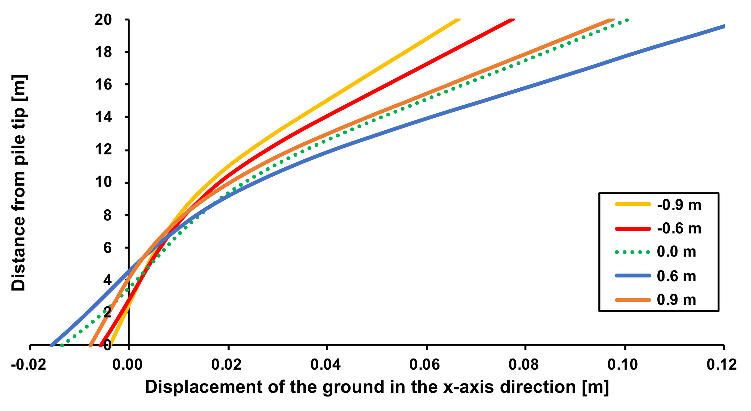
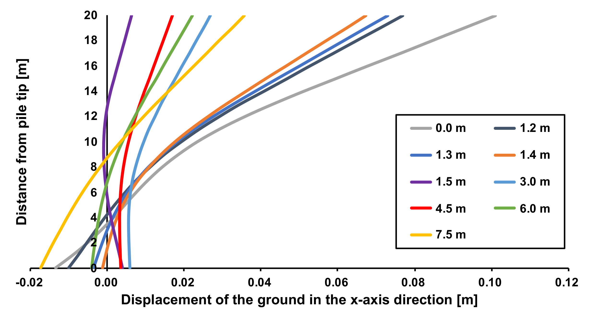
4.3. Position and Inclination of New Pile
When the installing position of a new pile is shifted only in the x-axis direction and the origin shown in Figure 6 is aligned with the center of the new pile, the degree of inclination of the new pile is verified. In this study, the installing position of the new pile is shifted from −0.9 m to +7.5 m in the x-axis direction.
Let us assume that there are two types of soil with different mechanical properties (equivalent to Case-3). As shown in Figure 6, there are two types of soil, one soil with an N value of 50 and another soil with an N value of five. The installing position of the new pile is 0 m, which is the boundary between the two types of soil, namely, the origin given in Figure 6 and the center of the new pile. The new pile can be moved only in the x-axis direction. For example, if the new pile is placed one meter away from the soil with an N value of 50, it will be expressed as −1 m. The load acting on the pile head of the new pile is 200 N/mm2.
Figure 12 shows the displacements of a new pile when the new pile interferes with the two types of soil at the installing position. The specific displacements of the installing positions are ±0.25, ±0.4, and 0 m. Comparing the installing positions of these five new piles, it can be confirmed that the new pile whose installing position is shifted by +0.4 m is the most inclined.
Figure 12.
Displacements of new pile at installing position.
Figure 13 shows the displacements of the new pile when the installing position of the new pile is shifted by ±0.6 m and ±0.9 m. If the installing position of the new pile is shifted by 0.6 m, the new pile will interfere with either the soil with the N value of 50 or the soil with the N value of five. Comparing the installing positions of the five new piles, including the case where the installing position of the new pile is shifted by 0 m, the installing position that is shifted by +0.6 m is the position where the new pile is the most inclined. In addition, even when the installing position is shifted by the same 0.6 or 0.9 m, the displacements of the new pile are different between the soil that is shifted to the soil side with an N value of 50 and the soil that is shifted to the soil side with an N value of five.
Figure 13.
Displacements of new pile when installing position is shifted by ±0.6 m and ±0.9 m.
The displacement and the inclination of the new pile are smaller when the installing position is shifted to the soil side where the N value is 50. Figure 14 shows the displacements of the new pile when the installing position of the new pile is shifted by +1.2 m or more. The greater the distance of the new pile from the origin, the smaller the displacement of the new pile and the smaller the inclination.
Figure 14.
Displacements of new pile when installing position is shifted by +1.2 m or more.
The installing positions where the new pile is the most inclined are +0.4 and +0.6 m. Therefore, the installing position that is shifted by +0.5 m from the origin, where the new pile is in contact with the soil with an N value of 50, is the position where the new pile is more inclined. In addition, as a method of suppressing the inclination of the new pile, if the installing position of the new pile is changed, it may be necessary to increase the distance from the boundary between the two types of soil.
5. Conclusions
In this study, it was assumed that after the removal of the existing pile, a difference in the mechanical properties between the backfilled soil and the original soil would occur, and that a new pile would be installed on the soil from which the existing pile had been removed. The effect of installing a new pile on the boundary between two types of soil with different mechanical properties was evaluated by a three-dimensional linear elasticity analysis. The results obtained are as follows.
- (1)
- When a new pile was installed at the boundary between two types of soil with different mechanical properties, most of the new pile was inclined to the soil side where the N value was relatively small.
- (2)
- When a new pile was installed at the boundary between two types of soil with different mechanical properties, the new pile warped so as to rise to the soil side where the N value was relatively large.
- (3)
- When a new pile was installed at the boundary between two types of soil with different mechanical properties, the new pile hardly inclined in the direction perpendicular to the boundary between the two types of soil.
- (4)
- When driving a new pile, the greater the load acting on the pile head, the more the new pile was inclined, and the smaller the load acting on the pile head, the less the new pile was inclined.
- (5)
- When a new pile was installed at the boundary between two types of soil with different mechanical properties, the inclination of the new pile was suppressed by increasing the distance from the boundary between the two types of soil.
Finally, there are two suggestions presented for future research. The first is to perform an analysis based on data such as the characteristics of the surrounding soil at an actual site, the soil removed from the existing pile, the shape of the new pile, and the load acting on the new pile. In this study, the material parameters were set with reference to the literature. However, it is expected that employing the data used at an actual workplace will lead to the establishment of a practical standard for removing existing piles. The second is to develop measures to reduce the slope of new piles. In this study, the inclination of the new pile tended to be suppressed by placing the foundation some distance from the boundary between the two types of soil with different mechanical properties. However, this is not a fundamental measure. It is necessary to change the mechanical properties of the new pile, rather than relocate it. Therefore, one issue is to develop a material or a construction method for filling in the pulling-out hole upon the removal of an existing pile [,,,].
Author Contributions
Conceptualization, S.N. and S.I.; methodology, S.K., K.-i.S. and S.I.; validation, S.N. and S.I.; formal analysis, S.I.; investigation, S.K. and K.-i.S.; resources, S.N. and S.I.; data curation, S.N.; writing—original draft preparation, S.I.; writing—review and editing, S.N.; visualization, S.I.; supervision, S.I. and S.N.; project administration, S.I. All authors have read and agreed to the published version of the manuscript.
Funding
This research received no external funding.
Institutional Review Board Statement
Not applicable.
Informed Consent Statement
Not applicable.
Data Availability Statement
Not applicable.
Conflicts of Interest
The authors declare no conflict of interest.
References
- Inazumi, S.; Namikawa, T.; Kuwahara, S.; Hamaguchi, S. Influence of pulling out existing piles on the surrounding ground. Int. J. GEOMATE Geotech. Constr. Mater. Environ. 2017, 13, 16–21. [Google Scholar] [CrossRef]
- Kuwahara, S.; Inazumi, S. Settlement of surrounding grounds due to existence of pile pulling-out holes. Int. J. GEOMATE Geotech. Constr. Mater. Environ. 2019, 16, 81–85. [Google Scholar] [CrossRef]
- Kuwahara, S.; Inazumi, S.; Jotisankasa, A.; Chaiprakaikeow, S. Influence of the condition of pullout holes on the surrounding ground. Int. J. Geo-Eng. 2020, 11, 10. [Google Scholar] [CrossRef]
- Inazumi, S.; Kuwahara, S.; Nontananandh, S.; Jotisankasa, A.; Chaiprakaikeow, S. Numerical analysis for ground subsidence caused by extraction holes of removed piles. Appl. Sci. 2022, 12, 5481. [Google Scholar] [CrossRef]
- Inazumi, S.; Kuwahara, S.; Jotisankasa, A.; Chaiprakaikeow, S. Improvement mechanism of sodium carbonate on traditional composite filler. Ground Improv. 2021, 174, 132–139. [Google Scholar] [CrossRef]
- Inazumi, S.; Tanaka, S.; Komaki, T.; Kuwahara, S. Effect of insertion of casing by rotation on existing piles in removal of existing pile. Geotech. Res. 2021, 8, 25–37. [Google Scholar] [CrossRef]
- Inazumi, S.; Hashimoto, R.; Shinsaka, T.; Nontananandh, S.; Chaiprakaikeow, S. Applicability of additives for ground improvement utilizing fine powder of waste glass. Materials 2021, 14, 5169. [Google Scholar] [CrossRef]
- Inazumi, S.; Kuwahara, S.; Jotisankasa, A.; Chaiprakaikeow, S. Construction method for pulling out existing piles and influence of pulling-out holes on the surrounding ground. Geotech. Geol. Eng. 2020, 38, 6107–6123. [Google Scholar] [CrossRef]
- Inazumi, S.; Kuwahara, S.; Jotisankasa, A.; Chaiprakaikeow, S. MPS-CAE simulation on dynamic interaction between steel casing and existing pile when pulling out existing piles. Int. J. GEOMATE Geotech. Constr. Mater. Environ. 2020, 18, 68–73. [Google Scholar] [CrossRef]
- Inazumi, S.; Kaneko, M.; Tomoda, Y.; Shigematsu, Y.; Shishido, K. Evaluation of flow-ability on fluidization treated soils based on flow analysis by MPS method. Int. J. GEOMATE Geotech. Constr. Mater. Environ. 2017, 12, 53–58. [Google Scholar] [CrossRef]
- Inazumi, S.; Kaneko, M.; Shigematsu, Y.; Shishido, K. Fluidity evaluation of fluidisation treated soils based on the moving particle semi-implicit method. Int. J. Geotech. Eng. 2018, 12, 325–336. [Google Scholar] [CrossRef]
- Inazumi, S.; Shigematsu, Y.; Nakao, K.; Shishido, K. 3-D particle flow analysis for fluidization treated soils. Am. J. Civ. Environ. Eng. 2018, 3, 59–67. [Google Scholar]
- Nakao, K.; Inazumi, S.; Takaue, T.; Tanaka, S.; Shinoi, T. Evaluation of discharging surplus soils for relative stirred deep mixing methods by MPS-CAE analysis. Sustainability 2021, 14, 58. [Google Scholar] [CrossRef]
- Nakao, K.; Inazumi, S.; Takahashi, T.; Nontananandh, S. Numerical simulation of the liquefaction phenomenon by MPSM-DEM coupled CAES. Sustainability 2022, 14, 7517. [Google Scholar] [CrossRef]
- Lees, A. Geotechnical Finite Element Analysis: A Practical Guide; ICE Publishing: London, UK, 2016. [Google Scholar]
- Saini, S.; Goyal, E.T. Analysis of piled raft foundation using MIDAS GTS NX. Int. Res. J. Eng. Technol. 2019, 6, 5491–5499. [Google Scholar]
- Skempton, A.W. Standard penetration test procedures and the effects in sands of overburden pressure, relative density, parti-cle size, ageing and overconsolidation. Geotechnique 1986, 36, 425–447. [Google Scholar] [CrossRef]
- Dung, N.T.; Chung, S.G.; Kim, S.R.; Beak, S.H. Applicability of the SPT-based methods for estimating toe bearing capacity of driven PHC piles in the thick deltaic deposits. KSCE J. Civ. Eng. 2011, 15, 1023–1031. [Google Scholar] [CrossRef]
- Intui, S.; Soralump, S.; Inazumi, S. Behavior of bearing capacity on pile foundation during fluctuating groundwater level. Int. J. GEOMATE Geotech. Constr. Mater. Environ. 2022, 22, 24–31. [Google Scholar] [CrossRef]
- Cetin, K.O.; Seed, R.B.; Kiureghian, A.D.; Tokimatsu, K.; Harder, L.F.; Kayen, R.E.; Moss, R.E.S. Standard penetration test based probabilistic and deterministic assessment of seismic soil liquefaction potential. J. Geotech. Geoenviron. Eng. 2004, 130, 1314. [Google Scholar] [CrossRef] [Green Version]
- Gang, B.; Hwang, B. Empirical estimations of soil constants using standard penetration test N value. J. Korean Geoenviron. Soc. 2018, 19, 5–12. [Google Scholar] [CrossRef]
- Huang, S.; Wang, J.; Qiu, Z.; Kang, K. Effects of cyclic wetting-drying conditions on elastic modulus and compressive strength of sandstone and mudstone. Processes 2018, 6, 234. [Google Scholar] [CrossRef] [Green Version]
- Nakao, K.; Yamaguchi, H.; Hoshino, S.; Inazumi, S. Applicability of weighting method as measure for existing manholes against uplifting during liquefaction. Appl. Sci. 2022, 12, 3818. [Google Scholar] [CrossRef]
- Hara, A.; Ohta, T.; Niwa, M.; Tanaka, S.; Banno, T. Shear modulus and shear strength of cohesive soils. Soils Found. 1974, 14, 1–12. [Google Scholar] [CrossRef] [Green Version]
- Tarawneh, B. Predicting standard penetration test N-value from cone penetration test data using artificial neural networks. Geosci. Front. 2017, 8, 199–204. [Google Scholar] [CrossRef] [Green Version]
Publisher’s Note: MDPI stays neutral with regard to jurisdictional claims in published maps and institutional affiliations. |
© 2022 by the authors. Licensee MDPI, Basel, Switzerland. This article is an open access article distributed under the terms and conditions of the Creative Commons Attribution (CC BY) license (https://creativecommons.org/licenses/by/4.0/).