1. Introduction
Robot hands have great potential not only in our daily life but also in many complex industrial application scenarios such as action exploration, precise measurement, and manufacturing processes [
1]. As an essential end actuator of humanoid robots, the robot hand is the main medium of physical interaction between humanoid robots and the outside world [
2]. Developing a robot hand that can be as dexterous, versatile, and stable as a human hand is the ultimate goal of many researchers.
The human hand has 27 degrees of freedom (dof): the thumb has five dof, and the other fingers have four each. There are still 6 dof for translation, abduction, and flexion of the wrist, and its complex structure endows it with high dexterity [
3]. The human hand is an extremely valuable interactive tool with the three functions of perception, grasping, and operation. It can complete dozens of actions, such as grasping, holding, pinching, pressing, picking, touching, and wiping. Therefore, many robotics researchers worldwide have made imitating the human hand structure and actions the ultimate goal of research in this field [
4]. In 1919, G. Schlesinger studied the upper limb structure of natural creatures and proposed six basic grasping modes [
5]. These six grasping modes are the epitome of most actions a human hand can perform. Therefore, contemporary robot researchers are committed to integrating these grasping modes into their research results as much as possible.
From the 1980s, the initial research achievements for robot hands were mainly dexterous hands; they were often in the form of full drive, equipped with complex sensor systems and control algorithms [
6]. The Center for Engineering Design at the University of Utah and the Artificial Intelligence Laboratory at the Massachusetts Institute of Technology developed the Utah/MIT dexterous hand [
7] in 1986. It was driven by 16 individual pneumatic drives, and to control the position of the finger joint more accurately, a Hall sensor was installed in every finger joint. The complex structure of the Utah/MIT dexterous hand ensured its versatility, but the high cost and huge system limited its application value. Another excellent dexterous hand is the Stanford-JPL hand [
8]. It is a three-finger robot hand with nine degrees of freedom designed by J. Kenneth Salisbury and John J. Craig after the overall optimization of the structure, size, grasping force, grasping accuracy, and control system. However, the whole system is still very complex, which is not only expensive but also limited in application. Japan launched the Gifu hand [
9,
10,
11] in 2002; the motor is placed inside the finger, which reduces the size of the base. Its overall size is similar to that of the human hand, with 20 joints and 16 degrees of freedom. The shadow hand [
12], which imitates the anatomy of the human hand, is driven by tendon rope to realize flexible hand movement and an anthropomorphic grasping form. In addition, some other famous dexterous hands include the HIT/DLR-1 hand [
13], the HIT/DLR-2 hand [
14], and the BH series dexterous hands [
15,
16] developed by the Beijing University of Aeronautics and Astronautics. They all laid a solid foundation for developing dexterous hands, making the research in this field more mature. During this period, dexterous hands have made great progress. Excellent achievements such as the Gifu hand, shadow hand, and HIT/DLR hand not only have an anthropomorphic appearance, dexterous actions, and powerful grasping, but also the operating methods are more accurate and diverse. The continuous improvement of dexterous hand systems has encountered a bottleneck in the development process; although their functions are constantly being enriched and their operation is made more accurate, the complex system, high cost, and difficult-to-control algorithms make it difficult for dexterous hands to be applied in all scenes of industrial production and daily human life.
Therefore, researchers all over the world have been trying their best to reduce the dimensions of robot systems, and the underactuated robot hand has emerged and becomes a research hotspot. Canada’s Lavel University first developed the SARAH underactuated hand [
17,
18], which has a three-fingers structure. Each finger has three joints, and through a motor and pulling tendon rope, the operator can drive all the degrees of freedom. SARAH hand realized underactuated grasping function with very simple structure, it has advantages of high adaption to different objects, but the properties are hard to meet the requirements of practical application. The Robotiq Company developed the best-selling Robotiq underactuated hand [
19], which uses the characteristics of a five-link mechanism to perfectly integrate parallel pinching and adaptive enveloping into a two-finger robot hand. The Robotiq underactuated hand has a compact design, low weight, easy control methods, but good general grasping ability. Its design concept is very efficient, and simple mechanical transmission can meet most operating requirements; however, its functions and diversity must be further developed for more complex operations. In addition, some underactuated hands have developed the coupled grasping mode, forming the coupled and self-adaptive robot hands, such as the Southampton hand [
20], Manus hand [
21], and ASIMO hand [
22,
23]. They have endowed the robot hand with more anthropomorphic action characteristics and more detailed handling methods; however, the power and stability of the coupled grasping are limited. The TH-hand series [
24,
25,
26] of Tsinghua University have realized the adaptive grasping of objects with different driving methods; they not only enrich the theoretical basis of underactuated robot hands but also give robot hands better performance. Polytechnique Montréal proposed a parallel-drive 3-DOF underactuated finger [
27], which enhanced the performance and the versatility of underactuated hands. Cornell University used flexible materials to make a flexible gripper [
28], which greatly improves the adaptability of underactuated hands. Driven by the above achievements, underactuated robot hands have made great progress, but disruptive changes are still needed to change their shortcomings of insufficient functions.
After years of development, coupled grasping mode, parallel grasping mode, and self-adaptive grasping mode are three common and typical grasping modes [
29]. With the continuous innovation of technology and science, most underactuated robot hands with a single drive source can include two grasping modes [
30]. The Barrett hand [
31], Yale Multi-grasp Hand [
32], GR2 gripper [
33], PASA hand [
34,
35], LISA hand [
36], DISA hand [
37], and CISA-LS hand [
38] of Tsinghua University are some of the best examples. Based on the concept of grasping modes integration, these achievements greatly expand the functions and applications of underactuated robot hands; they achieve multi-functional composite while ensuring good performance. Tsinghua University is constantly exploring ways to integrate various grasping modes, and their latest achievement, the COPASA hand [
39], integrates three grasping modes into a three-joint finger, though its size is too large, and its grasping performance is limited.
In the current development trend, people hope that robot hands have versatility and multifunction. To make the function of robot hands more powerful, robotics researchers are also committed to developing multi-grasping mode robot hands. Among the current achievements, the underactuated robot hands, which integrate two kinds of grasping modes, are common to see. However, integrating three common grasping modes (parallel grasping mode, coupled grasping mode, and self-adaptive grasping mode) is still hard work. This is not only because the integration requires abundant work but also because the three grasping modes are somehow mutually exclusive. Given this phenomenon, this paper conceives a switchable fusion method and then develops an ESMGM hand that combines the three typical grasping modes mentioned above.
In the following sections of this paper, the ESMGM hand will be introduced in detail.
Section 2 will give the design concept,
Section 3 will describe the concrete structure of the ESMGM finger and ESMGM hand,
Section 4 will analyze the properties of the grasping performance,
Section 5 will present the prototype and the experimental results of the ESMGM hand, and finally,
Section 6 will give the conclusion and prospects.
2. Design Concept of the ESMGM Hand
In this section, the design concept of the ESMGM hand is proposed, which gives the basic scheme of integration of parallel grasping mode, coupled grasping mode, and self-adaptive grasping mode. Based on it, two important mechanisms, namely the switchable CPS mechanism and partial effective transmission mechanism, are developed to realize the function. The structure and working principle of these two mechanisms are also described in detail.
2.1. Integration of Multiple Grasping Modes
To realize grasping mode fusion, we need to choose the appropriate method to combine them according to the characteristics of the three grasping modes. Common methods include direct series fusion and parallel switchable fusion.
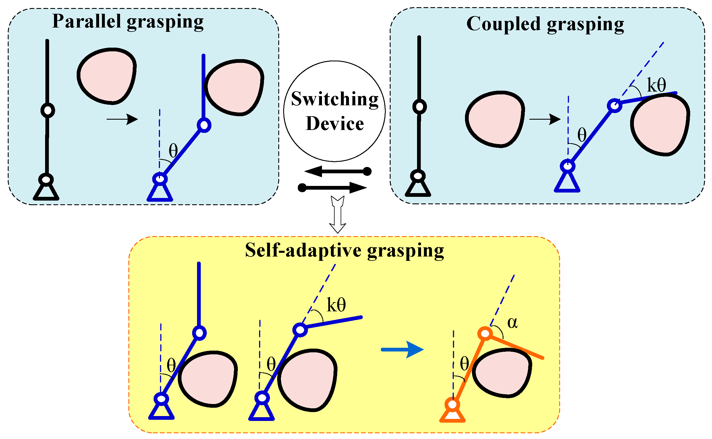
As shown in
Figure 1, the parallel grasping mode and coupled grasping mode always happen at the beginning stage of the entire grasping motion, but they put forward totally different requirements for the motion characteristic of the distal phalange and distal joint axis. Under parallel grasping mode, the distal phalange should keep parallel to the initial state. On the contrary, under the coupled grasping mode, the distal phalange should rotate coupled with the proximal phalange by a fixed ratio. Therefore, these two grasping modes, which should be arranged at the same stage, are mutually exclusive. In the above case, to effectively realize grasping mode integration, a switchable fusion method is proposed in the ESMGM robot finger. The operator can choose to execute with the parallel grasping mode or the coupled grasping mode for the first stage of the grasping motion, the switching of the two modes is realized by switching devices. The self-adaptive grasping mode requires that all phalanges completely envelop the object, so it is often arranged as the final stage of the grasping motion and forms a good connection with the parallel grasping mode or coupled grasping mode. Therefore, after the proximal phalange contacts the object, the first stage of grasping motion will be finished, and the ESMGM robot finger will enter the self-adaptive grasping mode; namely, the successful transformation from both parallel grasping mode and coupled grasping mode to self-adaptive grasping mode should be guaranteed with specific mechanism design. Above all, the parallel grasping mode and coupled grasping mode are integrated with a shunt connection method, and they are in series with the self-adaptive grasping mode.
To realize the fusion function mentioned above, a switchable fusion mechanism of coupled, parallel grasping, and self-adaptive grasping (switchable CPS mechanism) is proposed. It contains a motor, two-way gear sets, and a switching device, and it overcomes the certain incompatibility between parallel pinching and coupled enveloping; therefore, it is the foundation of the ESMGM hand and endows it with versatility.
Figure 2 shows the working principle diagram of the switchable CPS mechanism. The motor is fixed on the base and provides the torque, turning the proximal phalange. The two transmission gear trains, namely the parallel grasp gear train and coupled gear train, are arranged inside the proximal phalange. The lower ends of the two gear trains are connected with the switching device, which is arranged on the base, and the upper output end is fixedly connected with the distal phalange. According to the switching state of the switching device, the whole switchable CPS mechanism has two working modes, namely parallel grasping mode and coupled grasping mode.
The working mode could be set before operation through the switching device. Working processes of switchable CPS mechanism for parallel grasping mode and coupled grasping will be described in the following parts.
When the switching device is switched to the left, the whole switchable CPS mechanism will be under parallel grasping mode. The parallel grasp gear train is working. The switching device connects with the parallel grasp gear train; thus, it will be tensioned with the elastic element. Meanwhile, the coupled gear train is released and under a follow-up state.
After the motor starts, it drives the proximal phalange and rotates around the first joint axis. When focusing on the motion transmission of the parallel grasp gear train, the proximal phalange could be considered as the base. Thus, one can obtain the following equation according to the transmission principle of the gear train:
where
iHp1p3 indicates the transmission ratio from gear P1 to gear P3 relative to proximal phalange,
ωH indicates the rotation angular velocity of proximal phalange,
ωp1 indicates the rotation angular velocity of gear P1,
ωp3 indicates the rotation angular velocity of gear P3,
zp1 indicates the teeth number of gear P1, and
zp3 indicates the teeth number of gear P3. In particular, after a specific design, the gear P1 and P3 are selected with the same modules and teeth numbers, namely
zp1 =
zp3. The bottom gear P1 is obstructed through the spring; thus, the angular velocity is zero, and then one can obtain the angular velocity of gear P3 from Equation (1):
The top gear P3 is fixed with the distal phalange, so the angular velocity of the distal phalange relative to the base is zero. Therefore, during the whole operation, the distal phalanges remain parallel to each other, which is the parallel grasping mode.
When the switching device is switched to the left, the coupled grasping mode is chosen, and the switching device will make the elastic element hook up the coupled gear train part, so the coupled gear train is working, and the parallel grasp gear train is in a follow-up state. During the grasping process, when focusing on the motion transmission of the coupled gear train, the proximal phalange could be considered the base. Similarly, the following relationships can be derived according to the transmission principle of the gear train:
where
iHc1c4 indicates the transmission ratio from gear C1 to gear C4 relative to proximal phalange,
ωH indicates the rotation angular velocity of proximal phalange,
ωc1 indicates the rotation angular velocity of gear C1,
ωc4 indicates the rotation angular velocity of gear C4,
zc1 indicates the teeth number of gear C1, and
zc4 indicates the teeth number of gear C4. In particular, following a specific design, the gear C1 and C4 are selected with the same modules and teeth numbers, namely
zc1 =
zc4. The bottom gear C1 is obstructed through the spring; thus, the angular velocity is zero, and then one can obtain the angular velocity of gear C4 from Equation (3):
As the top gear is connected with the distal phalange, the angular velocity ratio between the distal phalange and proximal phalange equals the coupling coefficient, which means their motions are coupled. This is the coupled grasping mode.
2.2. Partial Effective Transmission Mechanism
After using the switchable CPS mechanism to realize the grasping mode fusion, it needs to drive the whole robot hand reasonably. Since the whole grasping action can be divided into two stages, the first of which is parallel grasping or coupled grasping, it then enters the self-adaptive grasping stage through a partial effective transmission mechanism, by which the movement process can be decomposed into two phases.
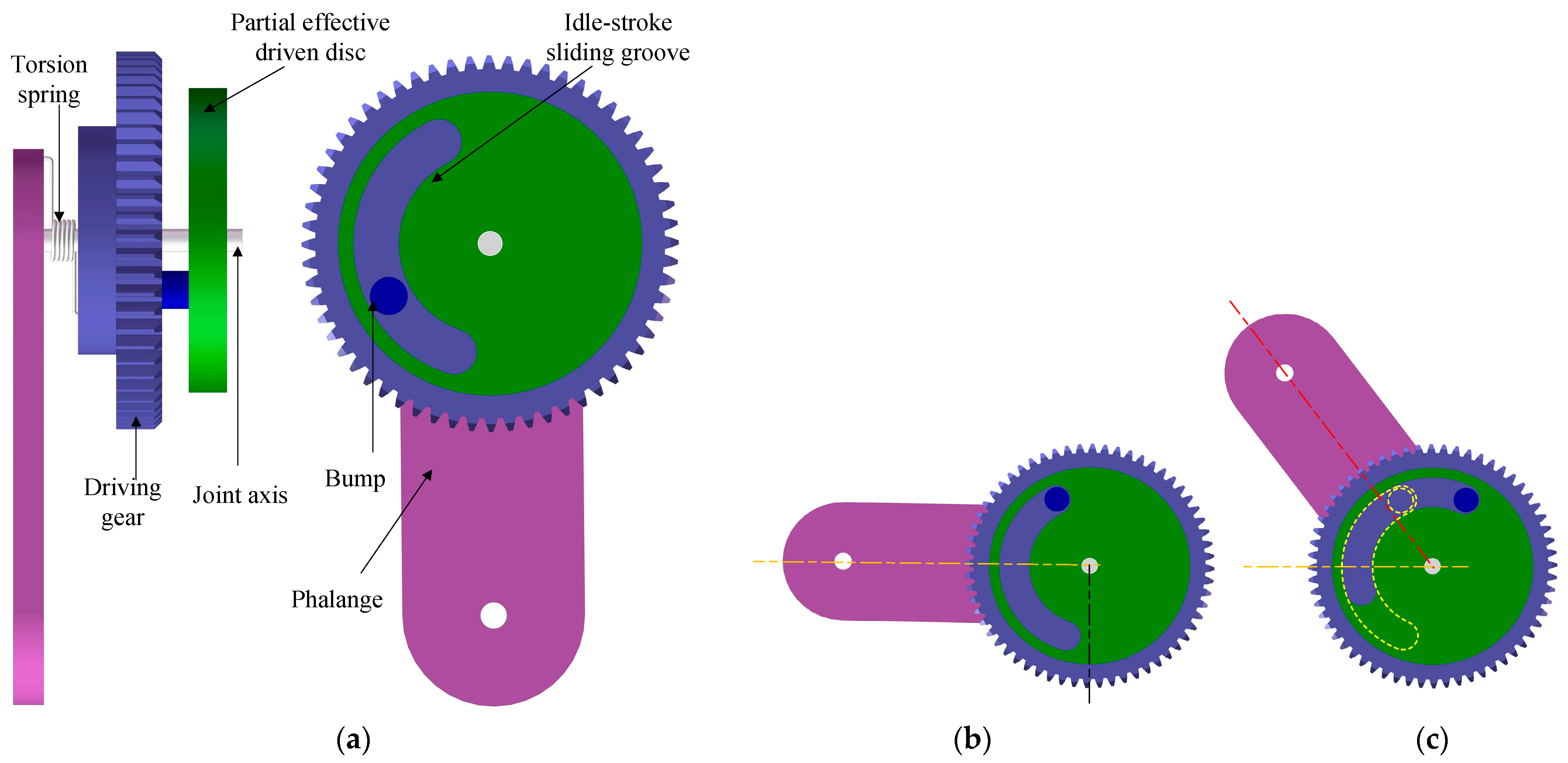
As shown in
Figure 3, the components of the partial effective transmission mechanism mainly include the phalange shell, a torsion spring, a driving gear, a joint axis, a bump, and a partial effective driven disc with an idle-stroke sliding groove. The whole motion period of the partial effective transmission mechanism includes two stages: the idle-stroke stage and the effective-stroke stage.
At first, the motor drives the driving gear rotation, and the mechanism will enter the idle-stroke stage from the initial position. The proximal phalange is attached to the driving gear with a torsion spring; thus, it will rotate under the torque of the torsion spring without external force interference. There is a bump on the driving gear, and during the idle-stroke stage, it will slide along the idle-stroke sliding groove, and the idle-stroke driven disc will maintain the resting stage. The idle-stroke stage ends when the entire idle stroke of the sliding groove is finished by the bump, the bump contacts with the edge of the groove, and the mechanism enters the effective-stroke stage. In this stage, the idle-stroke driven disc will rotate around the proximal joint axis because it is pushed forward by the bump.
By adopting the partial effective transmission mechanism, the ESMGM robot hand can integrate the two process stages expediently. Specifically, the ESMGM robot hand executes the parallel grasping mode or coupled grasping mode during the idle-stroke stage and executes the self-adaptive grasping mode after it moves into the effective-stroke stage.
3. Structure of the ESMGM Hand
In this section, the specific mechanical structure of the ESMGM finger and electromagnetic switching device are illustrated, and the working process and principles are also described in detail. Finally, an ESMGM Hand with a three finger structure was developed.
3.1. Mechanical Structure of the ESMGM Finger
The ESMGM hand consists of a palm and several ESMGM fingers. The ESMGM finger is the basic functional unit of grasping movement. Although the size and appearance of each finger of humans are different, for the robot hand, to simplify the design, all the ESMGM fingers adopt the same structure. According to the above design concept of the switchable CPS mechanism and the partial effective transmission mechanism, the specific structure of the ESMGM finger was designed. The ESMGM finger has a two-joint structure, and its appearance and specific parts structure are shown in
Figure 4.
The only motor is fixed on the base and powers the whole device through a worm gear transmission mechanism. The partial effective transmission mechanism, which consists of the torsion spring, the driven gear, the partial effective driven disc, and the bump, is embedded in the proximal phalange. The partial effective transmission mechanism connects with the proximal phalange through a torsion spring on one side and connects with the switchable CPS mechanism on the other. The power and torque from the motor are transferred to the driving gear of the partial effective transmission mechanism. Then it transfers the power to the proximal phalange and the switchable CPS mechanism during the effective-stroke stage.
The switchable CPS mechanism mentioned above is also set in the proximal phalange. When the partial effective transmission mechanism is in the idle-stroke stage, one of the two parallel setting switchable transmission gear trains will be limited by the tension spring, depending on under which grasping mode stage the electromagnetic switch device is triggered, and the other transmission gear train is in the follow-up state. When the partial effective transmission mechanism is in the effective-stroke stage, the bump on the driving gear drives the partial effective driven disc to rotate. Therefore the distal phalange, fixed with the third gear, will rotate with the same angular velocity, meaning the ESMGM finger enters the self-adaptive grasping mode.
The switching device can realize the switching of different working modes and the limit function of gears. It has different implementation methods, one of which is an effective embodiment of the electromagnetic switching device, which will be introduced in the next subsection.
Figure 5 shows the grasping movement process of the ESMGM finger. Due to its switchable function, it has two modes of operation, namely parallel and self-adaptive grasping mode (PASA mode) and coupled and self-adaptive grasping mode (COSA mode).
When the ESMGM finger is under PASA mode, the whole grasping process includes three stages. Besides the parallel grasping stage and the self-adaptive grasping stage, there is still an idle-stroke stage between them. That is because in most situations it is not possible that the time during which the proximal phalange touches the object matches the finishing time of the idle stroke perfectly. The whole process can be described as follows: the ESMGM finger begins with the parallel grasping mode (PA mode), the proximal phalange rotates, and the distal phalange keeps parallel to the initial attitude. If the distal phalange contacts the object earlier, the whole process will end. Conversely, if the proximal phalange contacts the object earlier, the object stops the proximal phalange, and the driving gear keeps turning against the torsion gear until the idle stroke of the partial effective transmission mechanism is finished. During this idle-stroke stage, each phalange of the ESMGM finger remains still. Then, the partial effective transmission mechanism enters the effective-stroke stage, and the tension spring will be elongated so that the ESMGM finger ends up in the self-adaptive grasping mode (SA mode) when the distal phalange contacts the object.
The grasping process of the COSA mode is similar to the process described above. The difference is that the electromagnetic switching device switches to the coupled grasping transmission gear train. Therefore, in the first stage, the ESMGM finger will execute coupled grasping mode (CO mode). Finally, the ESMGM finger will always end up in the self-adaptive grasping mode (SA mode).
3.2. Electromagnetic Switching Device
Figure 6 demonstrates the components of the electromagnetic switching device; it consists of two electromagnets and a sleeve shell wrapped outside. The two electromagnets are connected to the DC power supply through a single pole double throw switch, and only one electromagnet is in the electrified state at a time. When the ESMGM finger is in parallel grasping mode, the SPDT switches to the left side, and the electromagnetic iron on the left side is energized to attract the bottom gear of the parallel grasping transmission gear train and make it move together with the electromagnetic switching device. Similarly, if the ESMGM hand is in the coupled grasping mode, the SPDT switches to the right, and the electromagnetic iron on the right will limit the movement of the bottom gear of the coupled grasping transmission gear train.
3.3. Components of the ESMGM Hand
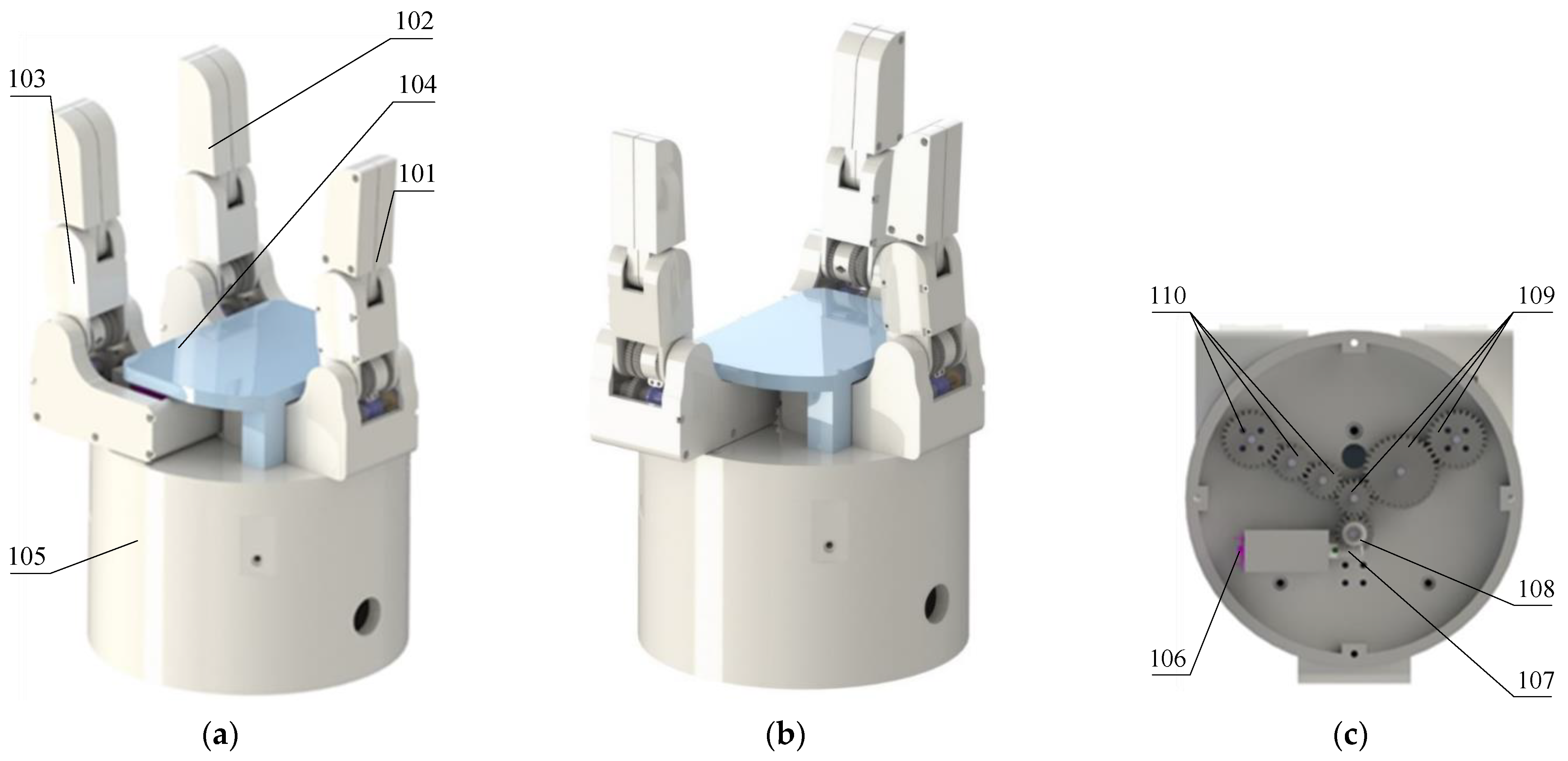
A healthy hand has five fingers and 24 degrees of freedom. However, for a robot hand, an overly complex structure and redundant degrees of freedom will inevitably mean higher cost and difficulty with control methods. Adhering to the practical concept of the underactuated hand, this research proposes an ESMGM hand with the structure of three fingers. The mechanical structure of the ESMGM hand is shown in
Figure 7; it mainly consists of three ESMGM fingers, a base, a palm, and the transmission system.
As the essential functional component, the ESMGM finger is mainly composed of several gear sets which transmit multiple grasping modes motions. Good transmission characteristics of gears ensure the high efficiency, sufficient grasping forces, and good grasping stability of the ESMGM hand. The switchable CPS mechanism which integrates three grasping modes ensures the effectiveness of the function. Based on the partial effective transmission mechanism in each ESMGM finger, large strokes are reserved for various grasping modes; thus, a large grasping motion range is guaranteed, and the ESMGM finger can achieve grasping action to a specific position with a different gesture. The electromagnetic switching method makes the ESMGM hand achieve fast and smooth switching without friction resistance. Its good property ensures that once a certain grasping mode is selected, the other transmission components will be completely in an idle condition without movement obstruction. Therefore, the ESMGM hand has good motion smoothness. The ESMGM hand is designed with a three-finger structure; the three ESMGM fingers are perpendicular to the palm and distributed on both sides of the palm. One finger is fixed on the base, while the other two are movable fingers. To give the robot hand better grasping characteristics, two fingers are set to be able to rotate around the rotation axis. The rotation of the two ESMGM fingers is realized through the transmission system. The motor provides the power to the two fixed shaft gear drive systems, and the end gears are fixed to the corresponding ESMGM fingers. If the motor starts, two ESMGM fingers will rotate at the same time and speed and in the opposite direction; the rotation range of each finger is 90 degrees.
Figure 7a shows the initial position of the ESMGM hand, in which the two movable fingers are opposite the fixed finger.
Figure 7b shows the state after the two movable fingers turn 90 degrees when they are opposite each other and perpendicular to the fixed one. In this way, the robot hand can grasp objects in the palm in all directions and is also endowed with wider grasping space, more dexterous movement, and better grasping stability. Thus its function can basically replace a robot hand with five fingers.
Some parameters of the ESMGM robot hand compared with a human hand are shown in
Table 1. According to various parameters, the size of the ESMGM robot hand is slightly larger than that of a human hand. However, its proportions are the same as that of human hands, with a high degree of personification. The ESMGM hand has greatly reduced the number of dofs, so its action is simpler than that of a human hand, but using an underactuated mechanism ensures self-adaptability. Two rotatable fingers ensure that an object can be grasped from all directions so that a robot hand with three fingers can basically replace the function of a traditional five finger structure.
5. Design of the Sensor and Control System
In addition to the mechanical structure, the ESMGM hand must also be equipped with the necessary sensing and control system to complete the operation. In this section, the sensing system and control system of the ESMGM hand are designed based on the Arduino controller, and the control algorithm is also implemented.
The sensing system is used to sense the mechanical information in the process of robot hand grasping, and the control system controls and manages the operation of the entire robot hand system. The ESMGM hand contains four motors and three electromagnetic switching devices, and each finger phalange is equipped with a pressure sensor. To simplify the complexity of the control system, the controller uses an Arduino Uno module based on an ATMEGA 328 chip, through its I/O interface, to complete the control of the motors and electromagnets and the reading and processing of pressure signals. In addition, an L298N driving module is needed to ensure the stable running of the motors, and a signal conversion module is also needed to convert the pressure signal into a readable analog input signal. The schematic diagram of the ESMGM robot hand sensor control system is shown in
Figure 18, and the control algorithm is shown in
Figure 19.
The controller drives the motors and electromagnetic switching devices through digital I/O interfaces, and the motion of three fingers occurs simultaneously. Digital I/O interfaces D0 to D3 detect the grasp signal, release signal, parallel mode signal, and coupled mode signal, respectively. Analog I/O interfaces A0 to A5 read analog signals converted by the conversion module from pressure sensors. In the process of the ESMGM robot hand working, the operator should first select the grasping mode, and the system will automatically set it to the selected working mode. After that, the control system will wait for the trigger of the grasp signal or release signal to complete the grasping action or release action. When the distal phalange of the ESMGM robot hand contacts the object, it will produce a force on the object. The pressure sensor detects the change in pressure. When the pressure value is greater than the set value, the robot hand automatically stops grasping. During the release action, when the ESMGM fingers return to their initial position, the process will end automatically.
6. Experiments of the ESMGM Hand
In this section, based on the prototype of the ESMGM hand, several experiments are performed to verify the excellent performance of the ESMGM hand. The motion verification experiments demonstrate the successful integration of three grasping modes, the universal grasping experiments illustrate the versatility and adaptability of the ESMGM hand, the grasping forces analysis experiments results are consistent with the theoretical analysis, and some key parameters illustrate that the ESMGM hand has the features of fast electromagnetic switching speed, good adaptability, high stability, fast response, and broad application prospects.
For the experiments, the ESMGM robot hand prototype was manufactured and assembled. The gear material was 45 steel, the worm wheel and worm are standard copper parts, and other non-standard parts are made of PLA through 3D printing. The experiments include motion process validation experiments, universal grasping experiments, and grasping forces analysis experiments. All the experiments are executed on the standard experiment platform. The equipment is powered by a 12 V student power supply; the grasping objects are common random objects in life. During the experiments, the grasping forces were measured with membrane pressure sensors. The running time is recorded with an electronic timer. The sizes of the object and the strokes are measured with a ruler, compass, and protractor. In order to illustrate the experiments more intuitively, a video recording the experimental processes is provided in the
Supplementary Material.
6.1. Motion Process of the ESMGM Hand
First, the feasibility of the basic functions of the ESMGM robot hand should be verified; that is, whether the ESMGM robot hand can normally complete the specified grasping action in the PASA and COSA modes.
Figure 20 and
Figure 21 show several frames in the entire grasping process under the PASA mode and COSA mode, respectively, when the ESMGM hand is grasping a weight. It can be concluded that the ESMGM robot hand can not only switch normally but can also realize the specified grasping mode, namely the PASA mode and COSA mode.
6.2. Universal Grasping Experiments
This chapter will cover the tests of the characteristics of the ESMGM robot hand in practical applications. Some daily objects were taken as the grasping targets. The robot hand selected the appropriate grasping mode to complete the grasping action. The experiments are shown in
Figure 22.
The prototype of the ESMGM robot hand was manufactured and assembled, and the universal grasping experiments were performed. The results show that the ESMGM hand can realize stable grasping for many objects in daily life, regardless of size, shape, and material, and it can even grasp multiple target objects. The switchable multiple grasping modes give the ESMGM robot hand more functions; the coupled grasping mode is suited for fast pinching of operation tools, such as pens, screwdrivers, and scissors, while the parallel grasping mode is suited for grasping flat objects such as paper boxes and squares. The self-adaptive grasping mode is suited for the powerful enveloping of the most irregular and heavy objects.
6.3. Grasping Forces Analysis Experiments
To verify the grasping force of the ESMGM hand, several grasping experiment scenarios are settled for validation experiments. The membrane pressure sensors are attached to each phalange, and the grasping forces are exerted through the elastic element to ensure the stability and uniformity of forces. The three grasping experiment scenarios are shown in
Figure 23. In scenario 1, the ESMGM hand grasps the rectangular object with parallel grasping mode. The size of the object is 80 mm × 60 mm. In scenario 2, the ESMGM hand grasps the screwdriver with coupled grasping mode; the diameter of the contact part is 12 mm. In scenario 3, the ESMGM hand grasps the cylindrical object with PASA mode and COSA mode, respectively; the diameter of the cylindrical object is 80 mm.
During the experiments, the variety of grasping forces of the distal and proximal phalanges have been recorded and shown in
Figure 24. For statistical analysis of several key parameters when the ESMGM robot hand realizes stable grasping of the objects, six validation experiments with the same group of configurations are performed, and the mean values and standard deviations of the measured parameters are calculated and recorded in
Table 3.
The above results in
Figure 24 and
Table 3 indicate that the variety of grasping forces under different grasping modes in experiments is consistent with the theoretical analysis results despite some differences. Considering friction, assembly error, and other factors, this is acceptable. In addition, through many experiments, some key properties of the ESMGM hand have been measured and recorded in
Table 4. The test results of key properties in the grasping process also reflect the excellent characteristics of the ESMGM robot hand, such as its fast response, large grasping space, and adequate grasping force.
Table 5 shows the grasping performance of the ESMGM hand compared with some other gripers. The biggest advantage of the ESMGM robot hand is that it integrates three typical grasping modes by using a specifically designed switchable underactuated mechanism. Thus, it has a versatile grasping function and a strong adaptive ability for different shapes, sizes, and materials. At the same time, compared with the current mainstream gripers on the market, it has a relatively large grasping stroke, sufficient grasping force, good grasping stability, fast response, and smooth grasping motion. The ESMGM robot hand still has disadvantages; for example, the size is slightly larger than a human hand, the weight is slightly heavier, and the accuracy of grasping is slightly worse than the Barret hand, all of which need to be further improved.
7. Conclusions
In this paper, a switchable parallel fusion method is proposed, which integrates three basic grasping modes into a two-joint single source driving robot hand. Based on this method, the ESMGM robot hand uses a switchable CPS mechanism to realize the electromagnetic switching function between the conflicting parallel grasping and coupled grasping modes. The partial effective transmission mechanism divides the motion into two phases and ensures the grasping motion always ends with the self-adaptive grasping mode. The ESMGM robot hand not only achieves functional expansion but also guarantees its property advantages. The operator can choose the appropriate grasping mode before an operation, the switching is fast, and the functions are abundant. The kinematic analysis and contact forces analysis show that the ESMGM hand has not only ample motion space but also sufficient grasping force for the grasping of daily life objects and small workpieces in industry production. To verify the properties of the ESMGM hand, grasping experiments were performed. The results show that it is suitable for grasping objects with different shapes, positions, and sizes due to combining the advantages of the three basic grasping modes.
However, through the comparison with various mainstream robot hands and grippers, it is found that although the ESMGM hand has achieved functional expansion, its performance under each grasping mode is not significantly better than other products. Firstly, due to the usage of gear sets, the size of the ESMGM robot hand is slightly larger than that of the human hand, which slightly hinders its dexterity. Secondly, elastic elements are used to realize the trigger and conversion mechanism of various grasping modes; thus, the maximal grasping forces are somehow limited. In future research, we should develop a more advanced mode integration method, more efficient transmission mechanism, and high-performance switching device to further improve the power and dexterity of the ESMGM robot hand. Furthermore, the ESMGM hand has only realized the integration of three common grasping modes; in reality, there are still many special works that need special action methods to grasp or handle. Therefore, grasping mode integration for more complex actions has always been necessary to develop underactuated robot hands. In the future, we will also try to develop robot hands with more specific grasping modes, such as pinching, side clamping, hooking, and touching. In general, the research in the field of the robot hand is endless.


