1. Introduction
Fishing with towed gear is a popular fish-catching method worldwide. The bag-shaped net can be towed through the surface, middle, and bottom layers of the sea. Because of its flexibility, this gear can be used on many types of fishing grounds by both small and large vessels for a wide range of target species [
1]. This fishing method provides a valuable food source for humans, however, it is one of the most energy-intensive food-production methods [
2]. Fishing with towed gear depends heavily on internal combustion engines powered by oil fuels.
Fuel costs in the fishing industry have risen substantially over the last 40 years, owing to three major oil price spikes. The rapid increase in fuel costs in recent years has severely affected the profitability of many fisheries. Additionally, the medium-term forecasts for oil prices indicate a high likelihood for further and steady increases [
1,
3]. Consequently, the increase in operational costs resulting from high oil prices in the past few years have become a serious concern for the fishing industry [
4].
The rise in fuel costs, labor shortages, and increases in other costs have caused a decline in the use of towed gear by fisheries [
5]. Since the 1980s, problems such as the decline of fishery resources, strict regulation of international fisheries, and competition have continued to threaten fishery management in this industry [
5].
Fishing with towed gear is increasing worldwide, more than other methods, and is responsible for approximately 40% of worldwide production [
6]. However, in East Asia, due to limited resources and competition between Korea, Japan, and China, statistics show that the production of fishing with towed gear in Korea and Japan has been decreasing [
7,
8].
To reverse this decline in the pair trawl fishery, a deficit reduction in fishery management is necessary. There are several ways to reduce this deficit, such as increasing the benefits of fishing and/or reducing expenditure. All operational expenses, such as fuel and labor, have risen substantially [
5]. Fuel expenditure has accounted for 10–20% of total expenditure since 2005 [
5]. Therefore, it is necessary to eliminate the deficit by reducing fuel costs. Research and development on various energy-saving technologies in fisheries have been promoted to reduce fuel costs [
1,
9,
10,
11,
12], but fuel costs continue to account for the majority of fishery expenditures.
Many efforts have been made to reduce fishing’s fuel consumption with towed gear, such as using fuel additives to improve the burning efficiency of engines and changing the vessel engine for improved fuel consumption efficiency [
5]. However, these efforts were not continued because they imposed a heavy burden on fishermen. In practice, using fuel additives and replacing vessel engines incurred high costs for the fishermen.
Therefore, one way to mitigate this issue for towed fishing gear is to reduce gear drag. It has been reported that low gear drag consumes less fuel than does existing gear [
1,
11]. Several ways to reduce drag have been proposed. Decreasing the towing speed with a low engine speed using a suitable nozzle and propeller [
13] is one suggestion. An appropriate nozzle and propeller could result in fuel savings of 20%. A slight reduction in cruising speed to and from the fishing ground reduces fuel consumption [
14]. However, with decreased towing speed, the catch of the target fish may also decrease. Another option is to use modern design trawl doors and nets to reduce drag. A large portion of drag in a towed bottom trawl is due to the resistance of the trawl doors required to spread the trawl [
14]. The modern design of trawl doors reduces this resistance, and the use of thinner and stronger twine and an increase in net mesh size can also result in substantial fuel savings [
14].
Based on these previous mitigation options, a different idea for reducing gear drag, which would be a smaller burden and a more realistic option for fishermen, was designed; combining appropriate netting, floats, and ground gear from conventional gear setups to decrease drag. This method is easier to implement than previous methods that attempted to reduce the total costs of fisheries using towed nets, while minimizing impacts and energy consumption.
In this study, we propose a design for fishing gear (low-drag gear) in which appropriate parts are placed on the gear. We prepared floats and ground gear that are typically used in the pair trawl fishery and conducted a series of flume tank experiments to understand the hydraulic drag force of conventional floats and ground gear. Additionally, different attack angles were also measured in the flume tank experiment. The frictional drag of ground gear was measured on dirt ground that had a similar terrain to the sea bottom. We present the results of drag measurements for floats and ground gear commonly used in trawl fisheries and discuss possible methods to reduce gear drag.
3. Results
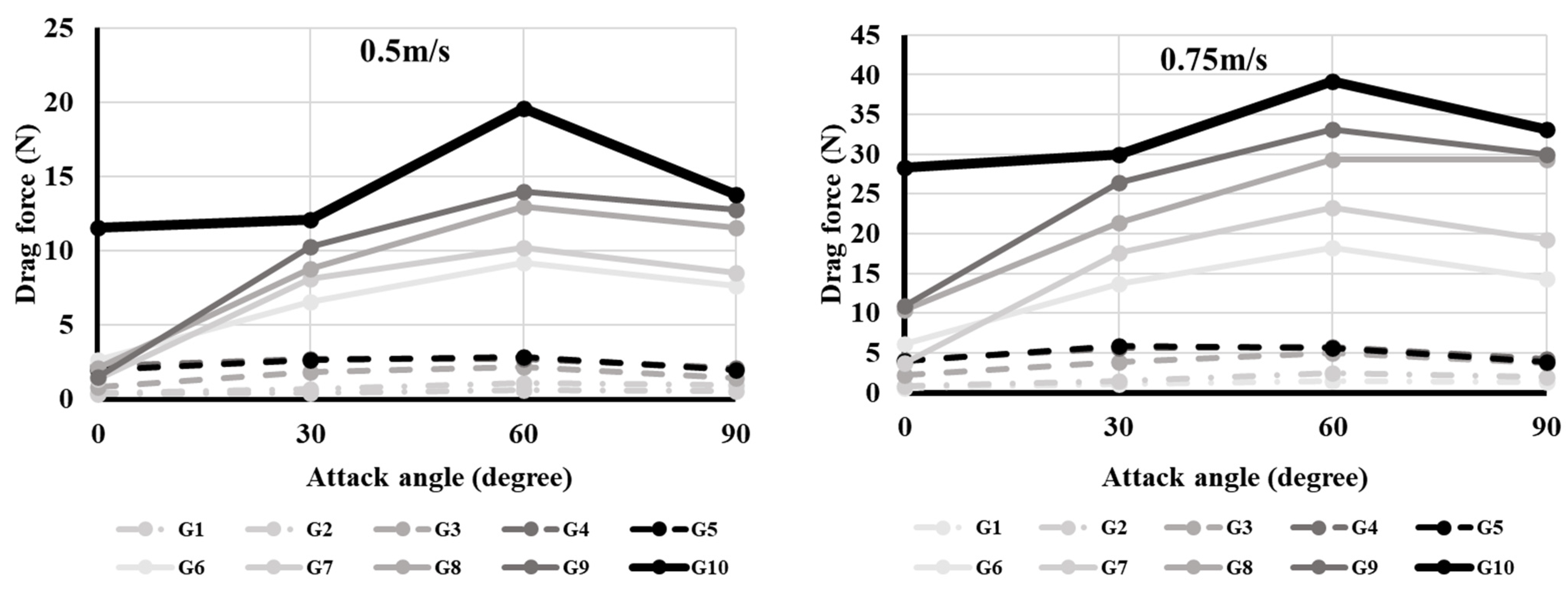
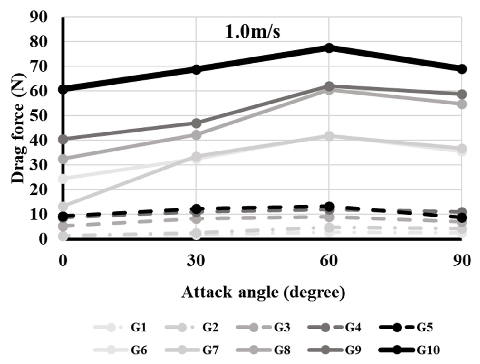
Figure 3 and
Figure 4 show the drag forces of the floats and ground gears at different attack angles for all flow speeds. The drag force was strongest when the attack angle was 60° for most floats and all ground gears at all flow speeds (
p < 0.05). However, drag force in some floats (F6 and F7) was not statistically significant at an attack angle between 60° and 90° (
p > 0.05). On the other hand, the smallest drag force was observed when the attack angle was 0° for all floats and ground gears at all flow speeds (
p < 0.05). The F10 float exhibited the strongest drag forces at all flow speeds when it was set at 60° (
p < 0.05). The F1 floats exhibited the smallest drag force with an attack angle of 0° for all flow speed (
p < 0.05). For the ground gears, G10 exhibited the strongest drag forces at all flow speeds when set at 60° (
p < 0.05). The drag force of G1 was smallest at 0° (
p < 0.05).
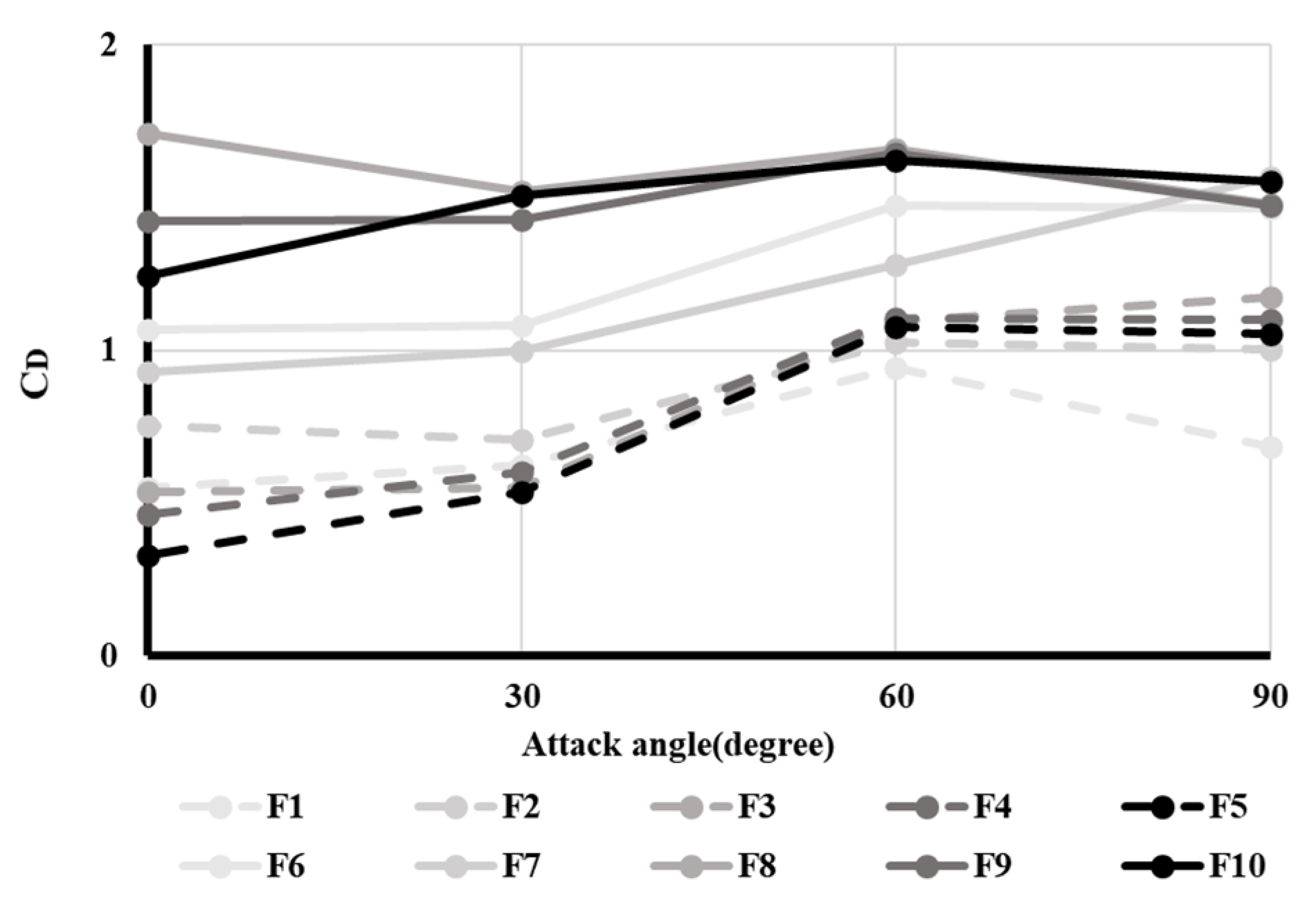
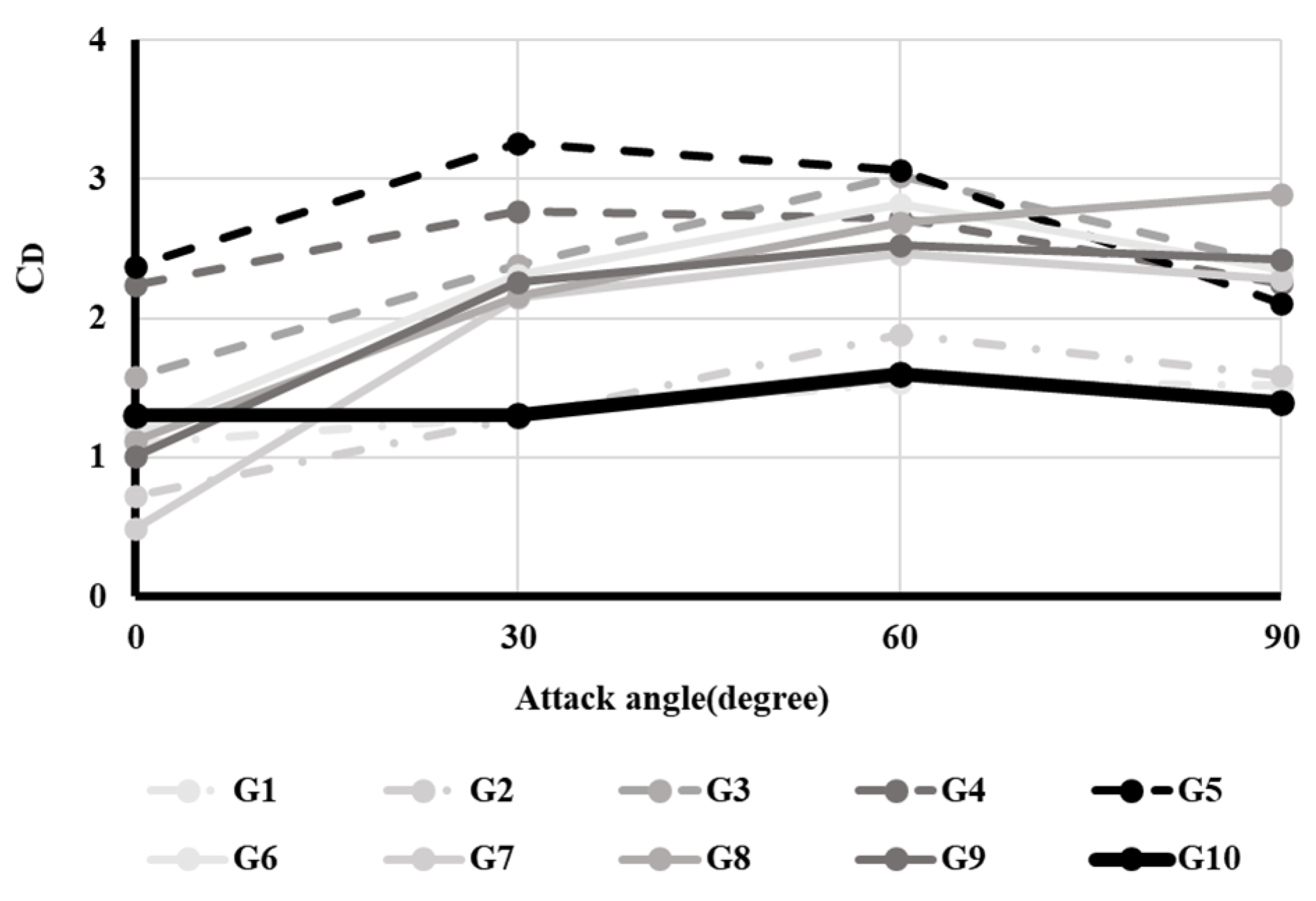
Figure 5 and
Figure 6 show the changes in the resistance coefficients of the floats and ground gears with attack angles, respectively.
Figure 5 shows that the resistance coefficients of the ellipsoid-shaped floats (F1–F5) were smaller than those of the sphere-shaped floats (F6–F10) at all attack angles. The resistance coefficients of the ellipsoid-shaped floats (F1–F5) increased when the attack angle increased; however, the values of the resistance coefficients of the sphere-shaped floats (F6–F10) were constant for various attack angles.
Among the ground gears (
Figure 6), the sphere-shaped ground gear (G10) showed a lower resistance coefficient than the cylinder-shaped gears (G3–G9) when the attack angle ranged from 30° to 60°. The resistance coefficient of the sphere-shaped ground gear (G10) increased when attack angles ranged between 0° and 60°, and then decreased from 60° to 90°. However, the resistance coefficients of cylinder-shaped ground gears (G4–G9) were smaller than those of ellipsoid and sphere-shaped gears at an attack angle of 0°, but was larger than those of ellipsoid and sphere-shaped ground gears at attack angles of 30° to 90°.
In summary, ellipsoid-shaped floats have better hydraulic characteristics to reduce drag than sphere-shaped floats. Cylindrical ground gears are better at reducing drag than spherical ground gears at a 0° attack angle. However, sphere-shaped ground gears are better at reducing drag at other attack angles (30°, 60°, and 90°) than cylinder-shaped ground gears.
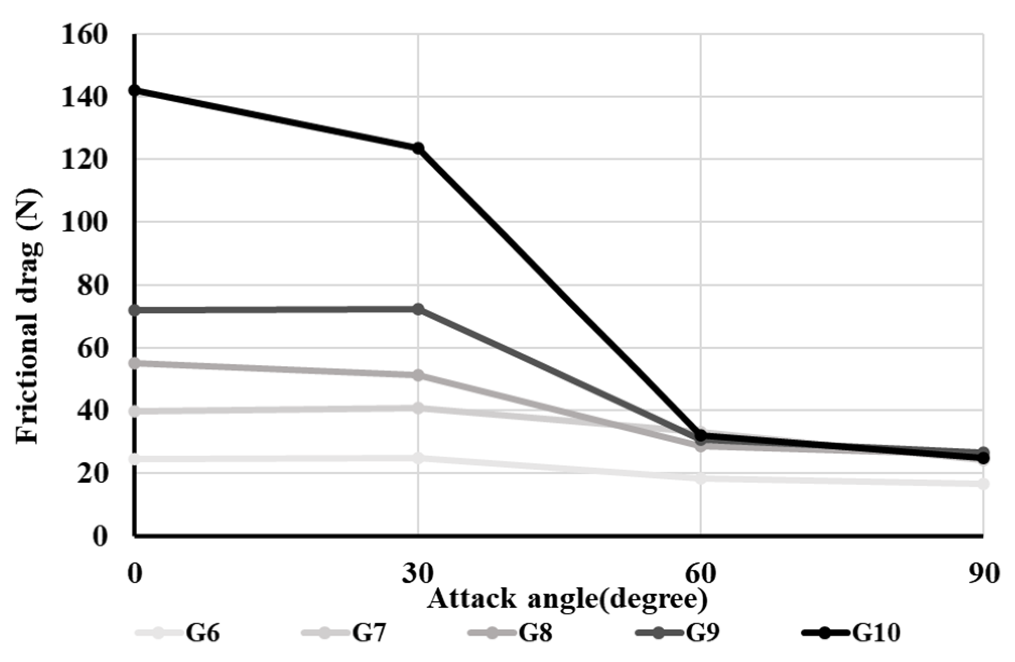
Figure 7 shows the frictional drag of ground gears (G6–G10) at different attack angles under a towing speed of 1.6 m/s. The frictional drag was low when all ground gears could revolve at attack angles of 60° and 90° (
p < 0.05). There was no significant difference between attack angles of 60° and 90° in all ground gears (
p > 0.05) Conversely, the frictional drag was larger in the non-rolling states at attack angles of 0° and 30° (
p < 0.05). The other ground gears showed no significant difference between 0° and 30° (
p > 0.05), only G10 showed a significant difference between 0° and 30° (
p < 0.05). In particular, the sphere-shaped ground gear (G10) exhibited the largest change in frictional drag. It decreased when the attack angle was large. The frictional drag increased with larger ground gears and declined with smaller ground gears.
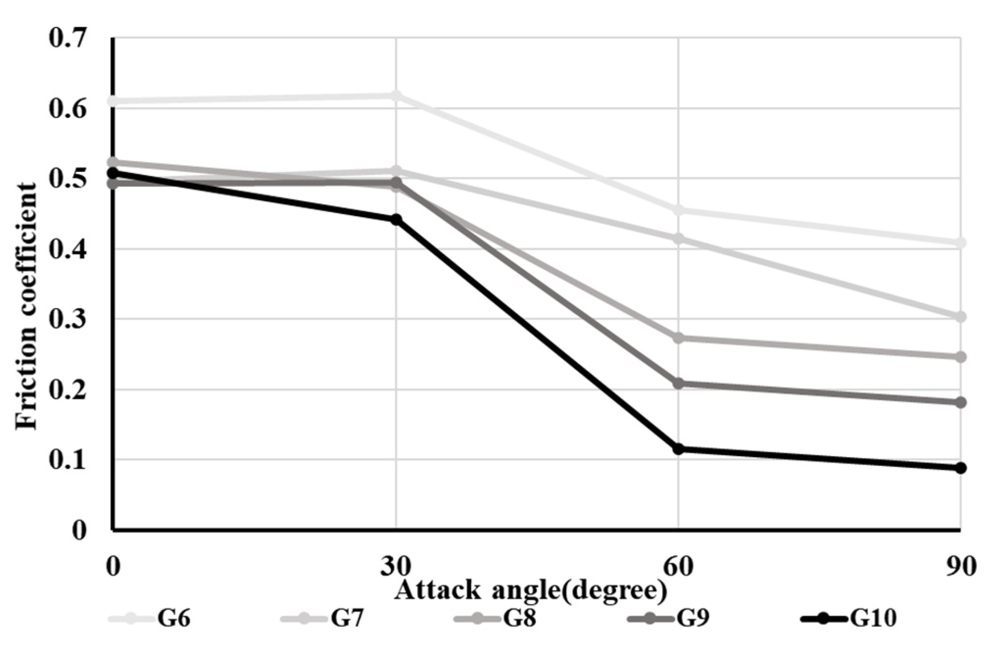
Figure 8 shows the relationship between the friction coefficient and attack angle for each gear. The friction coefficients decreased when the gears revolved at attack angles of 60° and 90°. In the range of 0° to 30°, the friction coefficients were large because the ground gears did not revolve when the attack angles were low (0° to 30°). The friction coefficient in the sphere-shaped ground gear (G10) was the lowest of all ground gears tested in this experiment.
Thus, both cylindrical and sphere-shaped ground gears are better at reducing the frictional drag at a 0° attack angle. At attack angles greater than 30°, the sphere-shaped ground gears are better at reducing the drag force.
To reduce the drag of towed gears, it is necessary to consider the size, shape, attack angle, and position of attachment of floats/ground gears. Therefore, information on buoyancy, sinking force, and hydrodynamic drag characteristics at various attack angles is required.
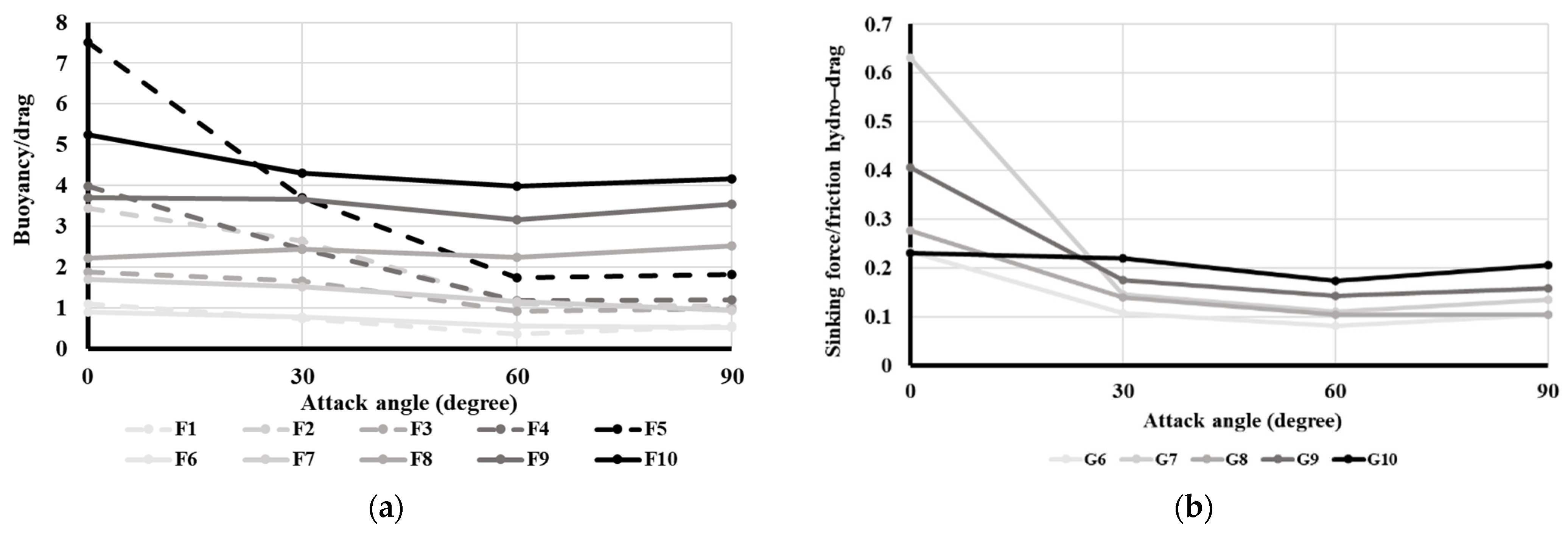
Figure 9 shows the relationship between the attack angle and the buoyancy/hydraulic drag ratio for floats and the relationship between attack angle and ratios of sinking force/hydraulic and frictional drag. The ellipsoid shape float, F5, had the largest volume and the highest ratio of buoyancy/hydraulic drag at a 0° attack angle, however, at other attack angles, F10, the sphere-shaped float with the largest volume, had the highest ratio of buoyancy/hydraulic drag among all floats. For ground gears G7 and G9, which were cylinder-shaped, the ratio of sinking force/drag at a 0° attack angle was higher than that of the other ground gears. However, at other attack angles, G10, which was sphere-shaped and had the largest volume, the ratio of sinking force/hydraulic and frictional drag was higher than for the other ground gears.
4. Discussion
This study confirmed that (1) the buoyancy/drag ratio of the largest volume sphere-shaped float was highest when the attack angle was 30°, 60°, or 90°, and that the largest volume ellipsoid-shaped float had the highest buoyancy/drag ratio when the attack angle was 0°; and (2) the drag of the ground gear consisted of hydraulic and frictional drags, and the sphere-shaped ground gear was advantageous for reducing drag when the attack angle was more than 30°. Cylindrical ground gear is better at reducing drag at a 0° attack angle. The hydraulic drag of float and ground gears is mainly thought to result from surface area and resistance coefficients.
The concept of reducing drag has not previously been considered for float and ground gear designs, probably because previous research mainly focused on providing stronger buoyancy for floats and maintaining tight contact with the seabed for ground gears [
2,
18].
Only one study has investigated float drag [
19,
20]. The resistance coefficients of sphere-shaped glass floats covered by various mesh size netting was between 0.4 and 0.7, which is lower than the results from our study, which found that the “C
D” of sphere-shaped floats ranged from 0.9–1.7. It is known that a sphere with rough or dimpled surfaces, such as a golf ball, has a lower resistance coefficient than a sphere with a smooth surface [
21]. In addition, the drag force in some floats (F6 and F7) was not statistically significant at an attack angle between 60° and 90°, as shown in
Figure 3. It is thought that because F6 and F7 had different sphere-shaped floats with ears for which the rope tied up to the head rope, these sphere-shaped floats with gears are different from other floats (F8, F9, F10).
If netting covers the sphere-shaped float, it might create a rough surface structure and consequently result in a lower drag. A study on covered sphere-shaped floats [
19,
20] suggests another idea to reduce the float drag other than what we addressed in this study: size, shape, attack angle, and finally, surface structure.
Studies on ground gears of towed nets have focused on their impact on the seabed. The impact of mobile fishing gear on the seabed is considered a serious problem for marine ecosystem conservation [
22,
23]. In fisheries using towed gears, reducing the contact area between the ground gear of the towed net and the seabed is one of the factors that can mitigate this problem [
24,
25]. Reducing the contact area of the ground gear also generates a lower frictional drag, and consequently reduces the drag of the ground gear, as presented in this study. Therefore, the reduction in contact area of the ground gear with the seabed is effective for seabed impact mitigation and fuel reduction of the fishery. One recent innovative study involves the development of a semi-circular spreading gear to generate a horizontally spreading force on the ground rope [
26]. The semi-circular spreading gear was mainly designed to have a small contact area on the ground, but it also effectively reduced drag. However, the self-spreading ground gear is very sensitive to small variations in geometry and may lose ground contact. Therefore, to overcome these disadvantages, a future study on the combination of various ground gears, such as tire ground gear, cylindrical rubber ground gear, iron ground gear, sphere-shaped rubber ground gear, and self-spreading ground gear, is important. In this study, a few ground gears with different shapes and volumes were measured in the flume tank experiment, and only four larger cylindrical ground gears and one sphere-shaped ground gear from the flume tank experiment were measured in the towing experiment. In addition, when combining ground gears, it is important to consider which ground gear has the lowest drag in the wing and entrance of the net, and how to reduce the drag by attaching the ground gears to the net. For this combination of ground gears, measurement of all shapes and materials of ground gears with various attack angles needs to be performed, and the redesign and rearrangement of ground gears must be considered through model and field experiments.
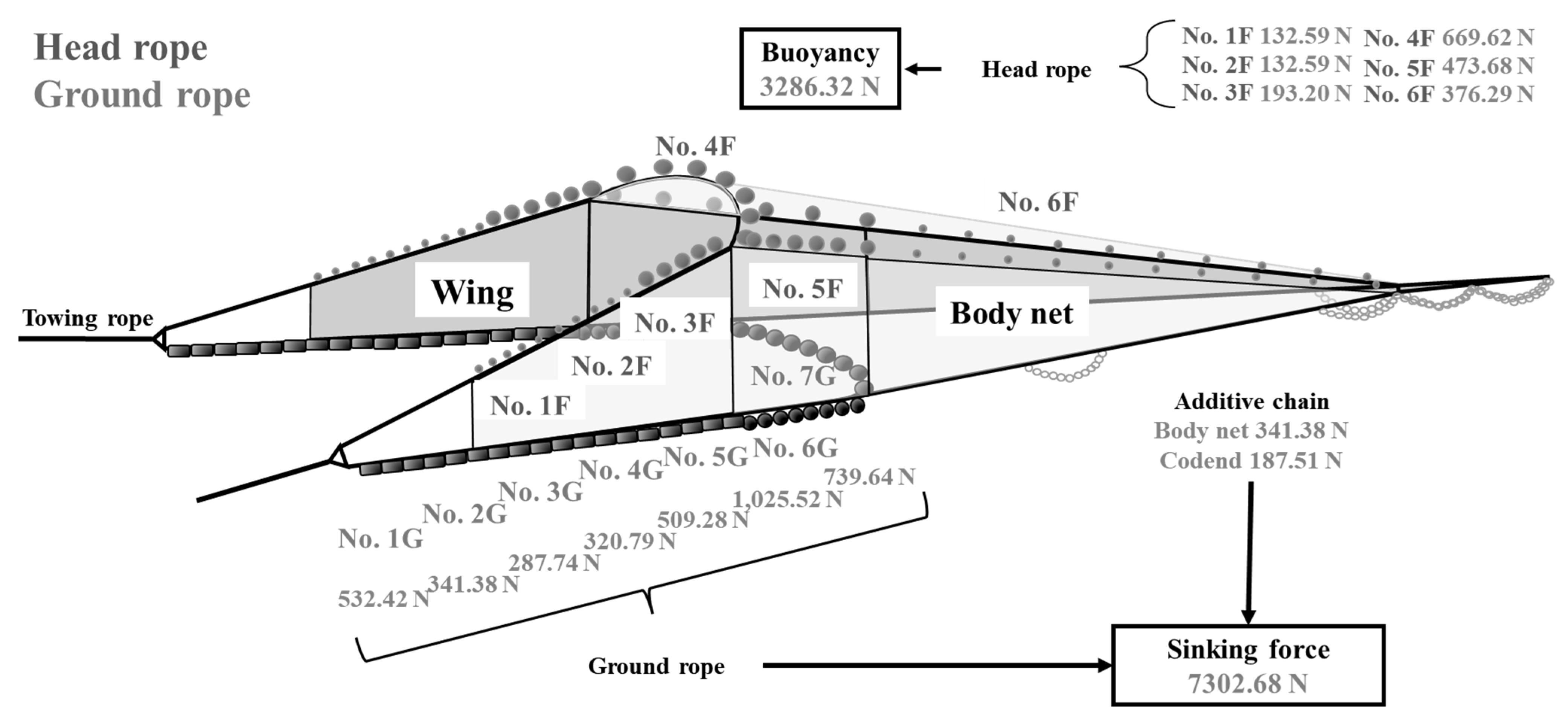
Finally, a preliminary calculation to reduce the drag for the pair trawl fishery (
Figure 10) was performed using the findings obtained in this study.
Figure 11 shows the net used in the pair trawl fishery designed in 2016 (General Foundation Japan–Korea·Japan–China Agreement Measures Fishery Promotion Foundation, 2017). The total length of the net was approximately 53 m, and the lengths of the head rope and ground rope were 55.15 m and 64.55 m, respectively. Floats and ground gears are mainly attached to the head rope and ground rope, respectively, but some floats are attached to the lacing lines of the net (No. 6F in
Figure 10). Total buoyancy of the floats used for the net was 3286.32 N and total sinking force was 7302.68 N (
Figure 10).
Sphere-shaped floats were used in the conventional design as shown in
Figure 11. Three types of ellipsoid and sphere-shaped floats (F5, F9, F10) with similar buoyancies (3237.96 N) to the present design were chosen to replace the suitable parts of the net. The ellipsoid float (F5) was arranged to place parts where the attack angles of the mounting positions (front part of the wing and lacing lines) were close to 0°. The drag of F5 at a 0° attack angle was used for three F5 floats at the edge of the head rope (No. 1F and 2F), and the drag at 30° was used for eight F5 floats on the two lacing lines (No. 6F). Spherical floats F9 and F10, were chosen for the other mounting positions. Their attack angles were set by considering the attack angles of mounting positions as follows: F9 on No. 3F of the head-rope with a 30° attack angle (front two floats) and 60° attack angle (one close to the entrance). Five F10 floats in No. 4F and four F10 floats had 60° attack angles, while the other F10 floats had 90° attack angles. For the 5F part, four F10 floats were placed at 60° attack angles. The attack angle of F9 was set to 60°. Four F5 angles were set at 30°, as explained.
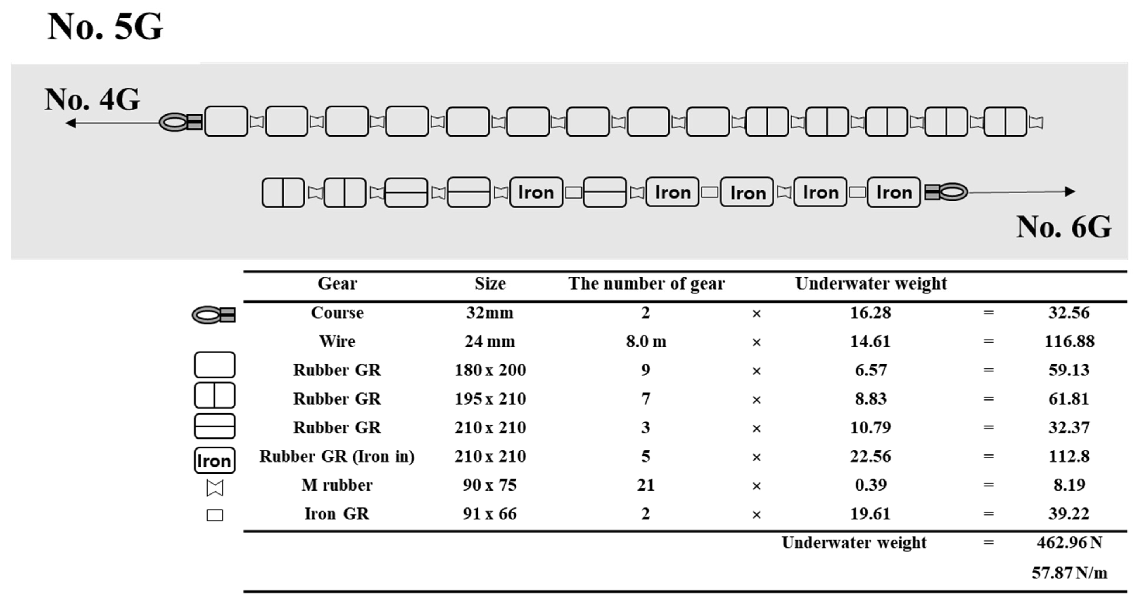
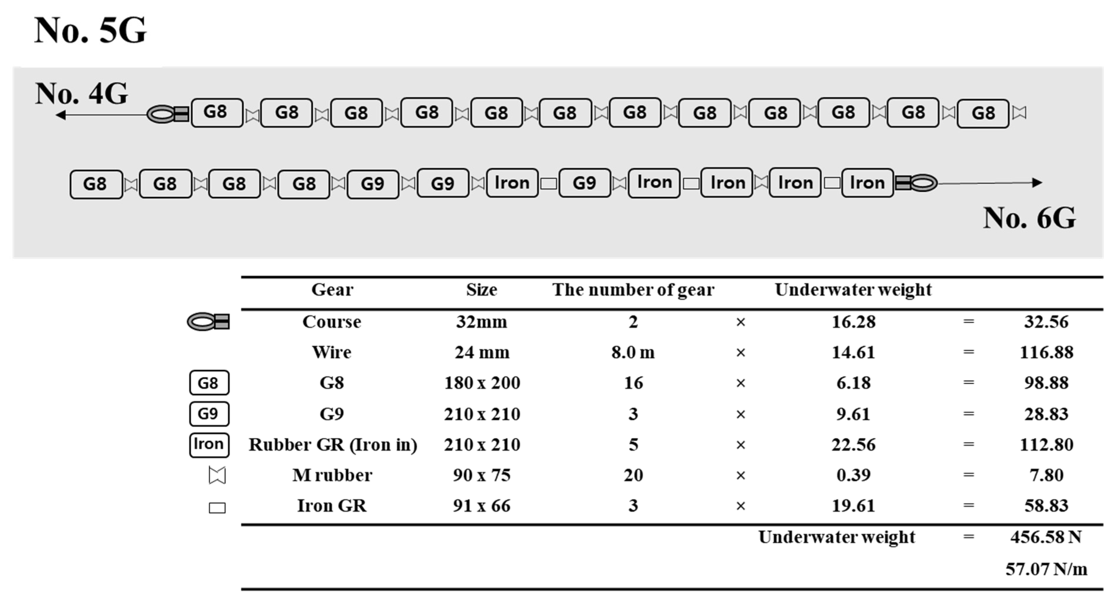
To estimate the drag reduction of the ground gear, three types of cylindrical and spherical ground gears with 7311.94 N of sinking force were considered. The detailed arrangements of ground gear in the ground rope design for the pair trawl fishery are presented in
Figure 12 and
Figure 13. To minimize the drag while maintaining the total sinking force, sixteen G8 and three G9 gears replaced the nineteen conventional rubber ground gears in the No. 5G part of the ground rope (
Figure 13). G8 and G9 were set at an angle of 30°. For Nos. 1G, 2G, 3G, and 4G, the ground rope parts were not replaced because they were already designed to reduce drag, and the redesigned ground ropes could have a larger drag than the conventional design. In addition, for No. 6G and No. 7G, the ground rope parts were not replaced because the ground gears used for No. 6G and No. 7G were larger than G10. In this study, only some available ground gears were changed from the design of the conventional net in the pair trawl fishery, although other ground gears with different shapes and materials were also used for the net. It was reported that the use of a small number of large ground gears in the ground rope resulted in fish escaping from the gap between the ground rope and the seabed [
27]. Because the estimation in this study is focused only on reducing the drag of ground gears, it is necessary to consider other functions of the ground rope, such as prevention of fish escape or protection of the net from contact with the seabed.
Thus, if nineteen larger sphere-shaped floats and twenty-eight of the biggest ellipsoid-shaped floats are replaced on the head-rope and lacing lines of the net, the drag of the head-rope parts (
Figure 11) can be presented, as shown in
Table 2.
The drag of No. 1F and 2F was reduced from 149 N to 38 N, 182 N to 99 N in No. 3F, 219 N to 147 N in No. 4F, 332 N to 238 N in No. 5F, and 298 N to 101 N in No. 6F. In total, the drag of the head rope was reduced from 1329 N to 661 N (total 50% reduction).
Regarding the ground gear, forty-eight cylindrical ground gears of the ground rope, which are similar in size but slightly lighter with low drag, were changed as shown by
Figure 12 and
Figure 13. The drag of No. 5G on the ground rope was reduced from 1790 N to 1718 N (
Table 3). No. 1G, 2G, 3G, 4G, 6G, and 7G were not redesigned in this study because these parts were already designed for low drag and there was no alternative ground gear to replace for low drag in this study. The drag force of the total ground rope was reduced from 10,195 N to 10,123 N (total 1% reduction).
From the reduction of drag of the head rope and ground rope, the reduction of fuel consumption would not be a large enough effect to reduce the drag of the head rope and ground rope. Regarding the drag in the trawl gear, the proportion of drag in the net is greater than the proportion of drag in the head rope and ground rope [
28,
29]. The total reduction was only 1.2% in this study. However, the trawl fishing gear is towed continuously for catching fish [
1,
2]. When calculating the drag reduction and fuel consumption rates from studies [
28,
29], a 0.8% fuel reduction efficiency was demonstrated per each haul. Many hauls using low drag gear in which the head rope and ground rope have been rearranged could save fuel costs due to the lower fuel consumption effect.


