Abstract
The conventional torque sharing function (TSF) control strategy in a switched reluctance motor (SRM) has higher torque ripple due to the weak torque tracking ability with an increase in speed. A non-unity torque sharing function (NUTSF) is proposed in order to minimize the torque ripple. Firstly, the working principle of the conventional TSF is introduced, and the causes of higher torque ripple are analyzed. Secondly, the NUTSF control strategy at each sub-region, where the two-phase exchange region is further divided into region 1 and region 2 based on the inductance characteristics, is proposed, and an optimization algorithm at each sub-region is applied so that the TSF is more suitable for the inductance and torque characteristics of the motor. Finally, a three-phase 6/20 SRM is taken as an example for simulation analysis and a prototype experiment. The results show that the proposed control strategy can effectively reduce the torque ripple of an SRM at a wide speed range.
1. Introduction
The switched reluctance motor (SRM) has a unique doubly salient structure and, no winding on rotor, and has a low cost and durability, which makes it a good prospect for application in electric vehicles and the aerospace field [1,2]. However, an SRM has a higher torque ripple, vibration and noise compared with other motors.
The high torque ripple can be further reduced by optimizing the SRM’s structure and improving the control strategy [3,4]. A vibration prediction method based on multi-physical analysis was proposed, which has a high prediction accuracy for SRMs [5]. According to the nonlinear characteristic of SRM, the turn-on angle and turn-off angle are designed, in [6,7], to reduce the torque ripple. In [8], the influence of the turn-on and turn-off angles on the current harmonic was analyzed, and the law between the vibration and conduct angles was obtained; it was concluded that the order of the harmonic is related to speed and load. The literature [9] shows that the vibration and noise can be suppressed by eliminating the third harmonic in the radial force of an SRM based on the relationship between the radial force and vibration. The noise of an SRM can be reduced by improving the harmonic current, as shown in [10]. A new direct torque control method was proposed, where a controller based on the Lyapunov function was obtained, which effectively reduces the torque ripple [11]. In [12], a fault-tolerant power converter scheme based on the entropy theory was presented, which can identify the faulty leg and the type of power semiconductor fault.
The torque sharing function, taken as an effective method to suppress the torque ripple, has been widely researched and applied in recent years. The four conventional TSFs have been evaluated and optimized [13]. A TSF control strategy based on a nonlinear formula was proposed in [14], which improves the tracking performance of the current. In [15], a new family of TSFs were proposed by optimizing the peak value of the current and the maximum absolute value of the change rate of flux linkage, which improves the efficiency of an SRM. The literature [16] takes into consideration three objects altogether in a family of TSFs: the efficiency, torque ripple and peak current, which expand the range of speeds. An offline TSF was presented in [17] where the offline TSF was selected by balancing the wide speed performance and efficiency, and the copper consumption of the SRM was reduced. A compensation strategy based on the TSF was designed in [18] where the torque error was compensated by a proportional–integral controller. The error between the torque reference and the actual torque was compensated in order to improve the torque tracking performance in the TSF [19]. The literature [20,21,22,23] applied the model to predict the current and torque, but it took a lot of memory. The improved TSF was designed offline by choosing the angle of the rotor position, and a neural network model was built [24]. In [25], the relationship between copper loss and the torque ripple was balanced by optimizing the offline TSF parameter.
The literature [26,27] showed how to control the SRM by using angle position control (APC). The current chopping control (CCC) method is commonly used in SRM drive control because of its simple calculation and good reliability, but the larger torque ripple limits its further application [28,29]. The many optimizing liaison (MOL) algorithm and gravitational search algorithm (GSA) were used to optimize the parameters of PI, and the turn-on and turn-off angles, respectively, in [30], and this showed that the MOL algorithm is superior to the GSA. In [31], the Q learning algorithm was applied to the current tracking control, which effectively improves the current tracking capability.
A non-unity torque sharing function at each sub-region is proposed based on inductance characteristics in order to reduce the torque ripple of an SRM. The causes of torque ripple are analyzed in detail, including the inductance characteristics and the influence of the torque sharing function. According to the inductance characteristics, a new region division of the two-phase exchange region is proposed, and an improved TSF is proposed in the new region, which conforms to the inductance characteristics and torque change trend. In addition, the improved TSF can also adjust the TSF at different speeds online according to the optimization algorithm of the TSF. Compared with the existing control strategy, this control strategy can not only enhance the torque tracking ability, but also reduce the torque ripple at different speeds, and it is easy to realize.
The organization of this article is as follows. In Section 2, the mathematical model of the SRM is introduced. Section 3 introduces the conventional TSF. In Section 4, the causes of the torque ripple of the conventional TSF and the proposed control strategy are presented. Section 5 shows the simulation analysis. The results of the experiment are presented in Section 6. Finally, the conclusion is given in Section 7.
2. Mathematical Model of Switched Reluctance Motor
Due to the special doubly salient structure of an SRM, the nonlinear factors, such as high saturation of the magnetic circuit and eddy current, will affect the performance of the SRM when its motor operates. If all the nonlinear factors are considered, the relevant calculation will be very complicated, and it is difficult to establish a unified and simple mathematical model for the SRM.
The SRM can be regarded as the combination of a mechanical and an electrical port. The electromechanical energy conversion formulas between the two ports include mainly a voltage formula, mechanical formula and torque formula.
The phase voltage formula can be expressed as follows
where , , , and are the voltage, resistance, current, induction electromotive force and flux linkage of the k-th phase windings, respectively.
The mechanical formula can be expressed as follows
where , , and are the electromagnetic torque, rotary inertia, rubbing factor and load torque, respectively.
The torque formula can be expressed as follows
where , and are the instantaneous electromagnetic torque, magnetic co-energy and the stored energy, respectively.
The SRM has strong nonlinear characteristics, so it is difficult to analyze and calculate the magnetic co-energy and stored energy, which makes it difficult to build an accurate and practical mathematical model of an SRM. This paper adopts a lookup table method to establish an SRM mathematical model in order to simulate and test the model more accurately and reliably.
In order to build an SRM mathematical model, the data of torque and flux linkage are obtained by a simulation calculation for a 6/20 SRM in finite element software (ANSYS). Figure 1 shows the structure of a 6/20 motor and the data of and .
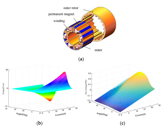
Figure 1.
Structure of 6/20 SRM and its simulation results: (a) structure; (b) torque ; (c) flux linkage .
According to Formula (1), Formula (2) and the data of and obtained from finite element analysis, the simulation model is built, as shown in Figure 2.
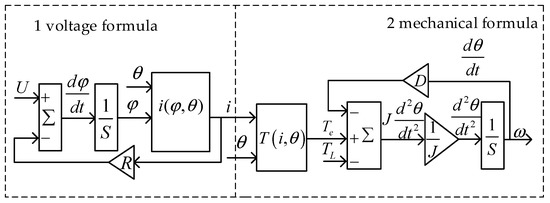
Figure 2.
Mathematical model.
The first part in Figure 2 is constructed according to the voltage Formula (1). Firstly, the phase voltage is subtracted by the winding voltage to obtain the change rate of flux linkage , which is integrated to obtain the flux linkage afterwards. Secondly, the phase current is obtained by calculating the reverse interpolation for the lookup table where the flux linkage is simulated by finite element analysis. The flux linkage and rotor position angle are used as inputs of the lookup table , and the current is output.
The second part in Figure 2 is constructed according to the mechanical Formula (2). The electromagnetic torque of each phase winding is obtained using the lookup table where the phase current and rotor position angle are used as inputs and the is simulated by finite element analysis. The angular velocity or () can be obtained based on the electromagnetic torque , load torque , friction factor and rotary inertia in Formula (2).
However, the linear model of electromagnetic torque is usually adopted in the qualitative analysis for the torque ripple control strategy of an SRM in order to highlight the basic torque characteristics of the SRM and simplify the calculation process. The linear expression of electromagnetic torque is as follows
where and are the current and inductance of the k-th phase windings, respectively.
3. Conventional TSF Control Strategy
3.1. Conventional TSF System
Different from other control strategies, the conventional TSF control strategy is based on the TSF to obtain the torque reference of each phase. Then, torque closed loop or current closed loop with the corresponding hysteresis control are adopted to reduce the torque ripple and realize the stable operation of the motor.
The block diagram of the conventional TSF system is shown in Figure 3. Firstly, the error between the speed reference and the actual speed obtained from the rotor of SRM is used as the input to PI controller where the parameter and is be adjusted offline, and the output to the PI controller is the torque reference . The is allocated to the torque reference , and of each phase winding in the TSF module. Secondly, the torque reference of each phase is subtracted from the instantaneous torque , and respectively, which are obtained from a lookup table which shows the nonlinear change of the torque with the current and position. And the error between the torque reference and instantaneous torque is calculated in the hysteresis module. Finally, the control signal generated from hysteresis controller is input into the power converter module to control the turn-on and turn-off of the IGBT to drive the SRM.
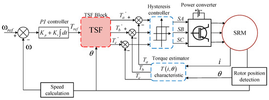
Figure 3.
Block diagram of the conventional TSF system.
3.2. TSF Module of Conventional TSF system
The TSF module of the conventional TSF system is based on the torque sharing function, so the value of the TSF will directly affect the winding current and motor torque ripple. It is very important to set a suitable TSF to improve the performance of the SRM. The sum of the TSF of each phase windings should always be equal to 1 in order to keep the total instantaneous torque at a constant value, so the TSF should satisfy the following general formula
where is the TSF of the k-th phase windings, is the number of phases, is the k-th phase torque reference, and is the total torque reference.
Take the exponential TSF as an example. The torque sharing function of the k-th phase is
where is the turn-on angle, is the turn-off angle, is the overlapping angle, is the rotor pole pitch, is the ascending area and is the descending area in the TSF.
An electrical period is composed of two regions. One region, where a single-phase winding is conducted to provide the total torque, is called the single-phase conduction region (SpC); the other region, where two-phase windings are conducted to provide the total torque, is called the two-phase exchange region (TpE). The TSF in the SpC is equal to 1, and the TSF of the outgoing phase decreases and the incoming phase increases in the TpE.
The waveforms of the TSF in the TpE are generally similar to a cosine, linearity, exponent and cube, as shown in Figure 4. Among the four waveforms, the torque ripple of a linear TSF is larger, followed by the cosine and cubic TSFs, and the exponential torque ripple has the best effect.
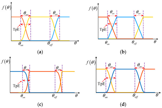
Figure 4.
Four conventional TSF waveforms in TpE: (a) cosine; (b) linearity; (c) exponent; (d) cube.
3.3. Region Allocated and Operation Principle of Conventional TSF
Based on the characteristic of the switching stator windings in an SRM, the rotor will rotate ahead of a rotor pole pitch angle after all the phase windings of the SRM are conducted once in turn. Taking the exponential TSF as an example, Figure 5 shows the region allocated at a rotor pole pitch angle based on the characteristics of inductance and the torque reference of each phase in the conventional TSF control strategy. The outgoing phase and the incoming phase start demagnetizing and exciting at the same position, respectively, so the turn-off angle of the outgoing phase is equal to the turn-on angle of the incoming phase; that is, . , and are the inductances of phases A, B and C in Figure 5, respectively; , and are the torque references of phases A, B and C.
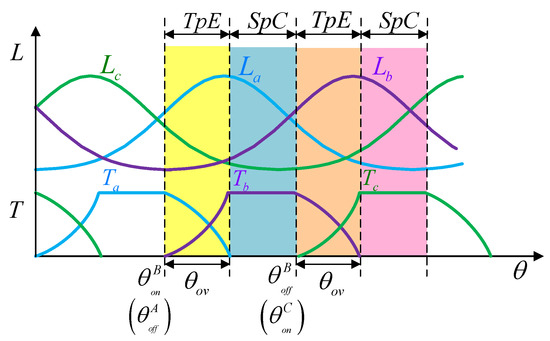
Figure 5.
Region allocated diagram of conventional TSF control.
The whole conduction region of a phase winding can be divided into the TpE and SpC. Taking phase B as an example in Figure 5, in the TpE, only the inductance of phase C decreases; both and increase. Phase C has been cut off and phases A and B have the current to provide positive torque in the TpE, where phase A is the outgoing phase whose TSF is presented in Formula (6) and phase B is the incoming phase whose TSF is presented in Formula (6). In the SpC region, only phase B has the current to provide positive torque whose TSF is 1 in Formula (6). Similarly, the other phases also work in the TpE and SpC regions according to their respective torque sharing functions.
It can be seen from the region’s allocated and operation principle the TSF of the incoming phase or outgoing phase in the conventional TSF control strategy is unified in the whole TpE and the shape is fixed.
4. Proposed NUTSF Control Strategy
4.1. Cause of Higher Torque Ripple in Conventional TSF Control Strategy
In order to reduce the torque ripple of the three-phase compound total torque, the actual torque of each phase is controlled according to the torque reference of each phase obtained by the TSF in the conventional TSF control strategy. However, the torque sharing function is united and fixed, so there is not good performance for torque ripple suppression at a wide speed in the conventional TSF control strategy.
In the first half of the TpE, the change rate of the inductance of the incoming phase is low, and the actual torque produced by the excited current is very small, according to Formula (4), because the excited current is just beginning to rise here. If the torque reference assigned by the TSF to the incoming phase is too large, the actual torque will not be tracked easily, resulting in higher torque ripple.
In the second half of the TpE, the change rate of the inductance of the incoming phase is high, which can produce enough excited torque to track the torque reference; the change rate of the inductance of the outgoing phase is high still and its torque is large afterward. Thus, a larger compound total torque is produced by both the incoming and outgoing phases in the second half of the TpE. If the torque reference allocated to the outgoing phase is large in the second half of the TpE, it will not only produce excessive actual torque, causing high torque ripple, but also make the outgoing phase difficult to demagnetize quickly, resulting in negative torque, which will affect the efficiency of the SRM.
In order to minimize the torque ripple, a non-unity torque sharing function based on each sub-region is proposed. The improved exponential TSF is formulated by using the characteristics of the inductance and torque of the SRM in the TpE in this NUTSF control strategy. The shape of the TSF is automatically adjusted to accommodate different speeds by changing the th-power and of the TSF, therefore enhancing the torque tracking ability and reducing the torque ripple.
4.2. New Region Allocation and Proposed TSF
The TSF allocates the torque reference to each phase winding according to the value of the waveform in the TpE, thus the torque reference of each phase winding is obtained. The waveform of the TSF directly affects the performance of torque ripple suppression in the TSF control strategy. A suitable TSF can not only reduce torque ripple, but also reduce current amplitude, which will improve the efficiency of the SRM. Therefore, the TpE is further divided into two regions according to the change rate of inductance, and the new TSF will be given for the incoming phase and the outgoing phase in each region.
A region allocated diagram is shown in Figure 6 based on the inductance characteristics, where is the turn-on angle, is the boundary point of the large inductance, is the sum of the turn-on angle and the overlapping angle, and is the turn-off angle. Taking phase B as an example in Figure 6, the inductance of the incoming phase rises in the TpE, but the inductance change rate is small in the first half of the TpE and increases intensely in the second half. Therefore, the TpE is divided into two regions, namely, region 1 and region 2, and the point where the inductance obviously rises is defined as the inductance boundary point . Region 1 is between and , and region 2 is between and the . The TpEs of the other two phases are allocated according to the same rule.
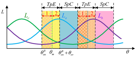
Figure 6.
Region allocated diagram of NUTSF control based on inductance characteristics.
According to the inductance characteristics in region 1 and 2, a non-unity torque sharing function (NUTSF) is designed based on each sub-region, as shown in Formula (7), in order to improve the conventional exponential TSF. Taking as the boundary point, each TpE is subdivided into two regions in the proposed TSF where function and function in Formula (7) are located, and the TSFs , , and are given in each region.
and in region 1 produce the torque of the incoming phase and outgoing phase, respectively, and and in region 2 produce the torque of the incoming phase and outgoing phase, respectively. The NUTSF can be expressed as follows
where is the boundary points, is the rotor pole pitch, is the exponential constant, is the overlapping angle, is the turn-on angle, is the turn-off angle, is the th-power of the function in region 1 and is the th-power of the function in region 2.
Comparing Formula (6) with (7), a TSF is divided into four when the NUTSF control strategy is used according to the torque characteristics of region 1 and 2. It can clearly be seen that the TSFs in each region are not united. The non-unity function will bring different function shapes, and the further adjustment of the function shapes depends on the th-power of and .
4.3. Principle of the Proposed Control Strategy
It is shown how the NUTSF works in Figure 7 where the and are the torque reference of the outgoing phase and incoming phase, respectively.
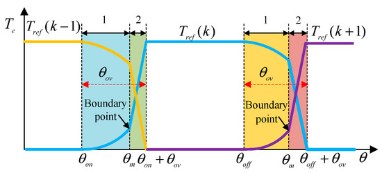
Figure 7.
Torque reference of NUTSF.
As for the incoming phase in region 1, the torque reference of the incoming phase is required to rise gently by using in order to make the actual torque of the incoming phase track the torque reference ; therefore, the torque reference of the incoming phase conforms more to the rising trend of the actual torque of the incoming phase.
A large change rate of inductance of the outgoing phase can produce a larger torque in region 1, while a small change rate of inductance of the incoming phase can produce a smaller torque. Thus, in region 1, the torque required for SRM operation is mainly provided by the outgoing phase. The increased torque of the incoming phase should be equal to the decreased torque of the outgoing phase in order to keep the total torque constant, so the torque reference of the outgoing phase is gently adjusted downward by using .
In region 2, the change rate of the inductance of the incoming phase becomes larger, and the current continues to increase, so the torque of the incoming phase becomes larger. The torque required for SRM operation is mainly provided by the incoming phase. Thus, the torque reference of the incoming phase should rise rapidly, and the torque reference of the outgoing phase should be decreased rapidly so that the total torque is kept constant and negative torque of the outgoing phase is not produced. Therefore, the torque reference of the outgoing phase in region 2 is adjusted by to decrease rapidly, while the torque reference of the incoming phase is adjusted by to increase rapidly. In this way, the SRM produces a stable total torque and reduces the torque ripple. The NUTSF control strategy is proposed to change the shape of the TSF, which makes the shape of torque reference more in line with the changing trend of actual torque.
The comparison between the NUTSF and the conventional TSF is shown in Figure 8 where the solid line indicates the NUTSF and the dotted line indicates the conventional TSF. The slope of the NUTSF of the incoming phase and the outgoing phase in region 1 is small, while the slope in region 2 is steeper, and the torque reference of the incoming phase and the outgoing phase in region 1 and region 2 is better fitted to the change rate of inductance and the actual torque of each phase. The slope of the function in each region is determined by the th-power and th-power of the TSF.
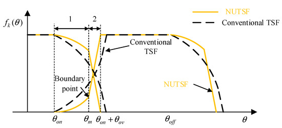
Figure 8.
Comparison between conventional TSF and proposed NUTSF.
The th-power of and are determined by the optimization algorithm of the TSF. Whether the th-power of and is changed depends on whether the torque error is within the specified range. The shape of the TSF is adjusted further; therefore, torque ripple will reduce further. The control flow chart is shown in Figure 9. Firstly, the initial values and are input, and then the torque error formula is used to obtain the torque error values and in regions 1 and 2, and the torque error formula is obtained from Formula (8)
where and are the total torque errors in region 1 and region 2, respectively; and are the torque errors of the outgoing phase in region 1 and region 2, respectively; and are the torque errors of the incoming phase in region 1 and region 2, respectively; is the torque reference of the outgoing phase, is the torque of the outgoing phase, is the torque reference of the incoming phase, is the torque of the incoming phase. It can be seen from Formulas (5), (7) and (8) that and in and are related to the torque sharing function. Formula (7) shows that the th-powers and affect the torque sharing function, which means that the torque errors and will be affected by and . Therefore, it is useful to set and properly to reduce torque errors and at different speeds, improve the torque tracking ability and reducing torque ripple. The adjustment formula of and is shown in Formula (9).
where and are the new th-power of and , respectively, in the iteration, and is the increment of the th-power and th-power value.
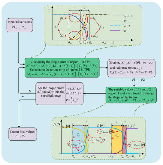
Figure 9.
Optimization algorithm of torque sharing function.
Whether and in region 1 and region 2 increase or decrease depends on whether and are positive or negative. If is positive in region 1, the present torque references and are large. It is concluded from Formulas (7)–(9) that the value of needs to be increased in this case in order to slow down the shape of the NUTSF, therefore reducing the value of the torque reference. If is negative, the torque references and are small. It is necessary to reduce the value of so that the shape of the NUTSF is intensified, increasing the torque reference. Similarly, the in region 2 can be obtained.
The torque errors of and in each region should be adjusted according to error limit , which is set based on the desired rate of torque ripple . The limit formula is shown as Formula (10).
where is the error limit, and is the desired rate of torque ripple.
If the torque errors and in region 1 and 2 are within the torque error limit, the present and are taken as the output of the controller, and the latest values of th-power and are obtained; that is, and . If and are not within the error limit, the values of and will be changed iteratively until the condition is satisfied.
According to the above-mentioned TSF optimization algorithm, the overall control system block diagram of the NUTSF control strategy is shown in Figure 10. The algorithm adjusts the TSF in region 1 and 2 online, and distributes the total torque reference by the new TSF module, which improves the torque tracking ability in the TpE and reduces the torque ripple at different speeds.
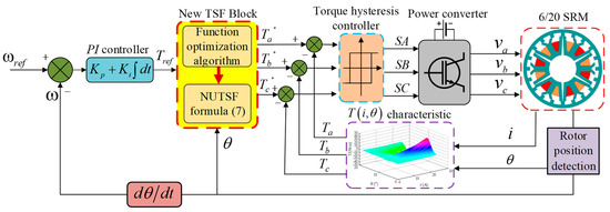
Figure 10.
Block diagram of the proposed NUTSF.
4.4. Comparison of the Existing and Proposed Schemes
In recent years researchers have proposed some control strategies to suppress the torque ripple of the SRM. The control strategies for controlling torque ripple are compared in detail in Table 1.

Table 1.
Comparison of torque ripple reduction methods.
The APC strategy only controls the turn-on angle of the SRM in [26,27], and there is no control strategy in the TpE, resulting in a larger current and torque ripple. The current chopping control (CCC) produces a lot of chopping to keep the current constant, leading to a larger torque ripple [28,29]. The intelligent algorithm is applied to the SRM in [30,31], but it takes a lot of training data to execute. The improved TSF in [24] is built, but it has a lower adaptability in a wide speed range. The parameter selection of the offline TSF and the construction of the GA algorithm are complicated in [25].
Different from the above-mentioned control strategies. The control strategy proposed in this paper is based on the region division of inductance characteristics, and the non-unit torque sharing function control strategies in different regions are designed according to the motor characteristics. The NUTSF in this control strategy is more in line with the changing trend of the actual torque. The optimization algorithm of the TSF changes the P1 and P2 th-power according to the torque error, so that the proposed NUTSF can be controlled online and effectively reduce the torque ripple in a wide speed range. In addition, the control strategy is simple and easy to implement, and it has good reliability when the speed changes.
5. Simulation Analysis
A 6/20 pole SRM model and its control system were built in MATLAB/Simulink based on the above theoretical analysis, and the effectiveness of the control strategy was verified. The simulation model is shown in Figure 11. The specific parameters of the 6/20 pole SRM are shown in Table 2. The instantaneous phase torque was obtained by using the lookup table in the simulation model.
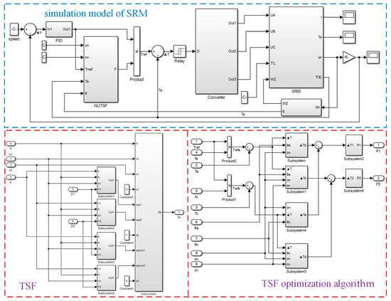
Figure 11.
Simulation model of SRM and one-phase NUTSF simulation model.
Table 2.
6/20 SRM parameters.
The conventional exponential TSF and the proposed TSF control strategy were adopted in the simulation model, respectively. The load torque was set to 5 N·m, and the SRM operated at 500 r/min and 1000 r/min, respectively. The torque ripple rate was defined to compare the performance of the two control strategies. The expression is as follows
where , and are the maximum, minimum and average torque, respectively.
When the working condition is such that the load torque is 5 N·m and the motor operates at 500 r/min, after adopting different TSF control strategies, the waveform diagram of the total torque, the torque of each phase, the torque reference of each phase and the current diagram of each phase are obtained as shown in Figure 12. In Figure 12 and Figure 13, ia, ib and ic are the phase A, phase B and phase C currents, respectively; Ta, Tb and Tc are the instantaneous torques of phases A, B and C, respectively; Ta*, Tb* and Tc* are the torque references of phases A, B and C, respectively; and Te is the total output torque.
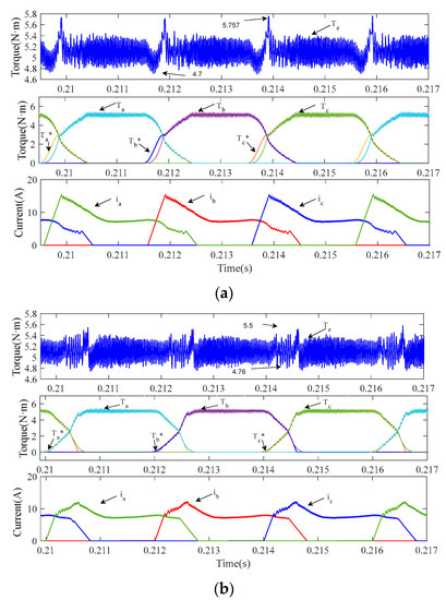
Figure 12.
Simulation waveforms of torque and current: (a) conventional exponential TSF at 500 r/min; (b) proposed NUTSF at 500 r/min.
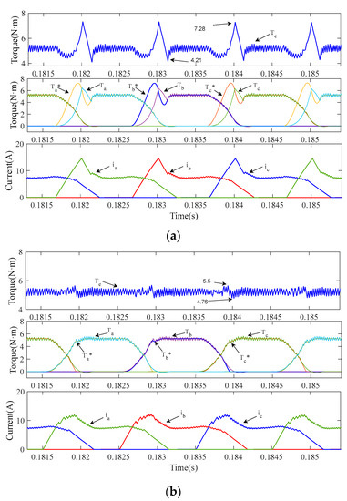
Figure 13.
Simulation waveforms of torque and current: (a) conventional TSF scheme at 1000 r/min; (b) proposed NUTSF at 1000 r/min.
The simulation result shown in Figure 12 demonstrates that when the SRM operates at 500 r/min, the total torque ripple of the two control strategies of the conventional exponential TSF and NUTSF is relatively small, but the NUTSF control strategy plays a better role in suppressing torque ripple. As shown in Figure 12a, at the start of the two-phase exchange region (region 1), the torque sharing function curve of the incoming phase of the conventional exponential TSF control strategy has a larger change rate (steeper shape) and the phase torque reference is larger. However, at the start of the two-phase exchange region, the smaller the change rate of the incoming phase inductance is, the smaller the actual incoming phase torque will be, resulting in the actual incoming phase torque being less than the incoming phase torque reference and the larger torque ripple will be. The torque of the conventional control strategy is between 4.7 and 5.75 N·m.
As shown in Figure 12b, the shape of the TSF is adjusted in the NUTSF control strategy according to the optimization algorithm of the TSF in the two-phase exchange region. The torque reference of the incoming phase increases slowly, and that of the outgoing phase decreases, which is more in line with the changes in the actual torque of the incoming phase and the outgoing phase, and the effective reduction in the torque ripple in the TpE. The torque of the NUTSF control strategy is between 4.76 and 5.5 N·m.
The waveforms of the phase current, the torque of each phase and the total torque obtained by the two TSF control strategies are shown in Figure 13 when the SRM operates at 1000 r/min. The simulation results show that the torque ripple of the conventional exponential TSF control strategy becomes larger when the SRM operates at 1000 r/min, while that of the NUTSF control strategy is still smaller. As shown in Figure 13a, with the increase in speed, the interval time of the two-phase exchange is shortened, and the conventional control strategy needs to make the incoming phase torque rise to a larger torque reference in a shorter time. However, the actual incoming phase torque cannot quickly rise to the torque reference due to its low change rate of the inductance at this stage and the larger error between the two results in a larger torque ripple. The torque of the conventional control strategy is between 4.21 and 7.28 N·m.
As shown in Figure 13b, the shape of the TSF is adjusted by the NUTSF control strategy in regions 1 and 2 in the TpE, which reduces the error between the torque reference and the actual torque, and effectively reduces the torque ripple, which is between 4.75 and 5.63 N·m in TpE.
6. Experimental Verification
The experimental platform to verify the proposed TSF control strategy is shown in Figure 14. The TSF control strategy is implemented at the TMS320F28335 DSP platform, the rotor position is measured by an encoder with a 15-bit absolute value, the load acts as a magnetic brake and the asymmetrical half-bridge converter is employed to drive the SRM. The parameters of the SRM prototype are consistent with those in the simulation experiment.
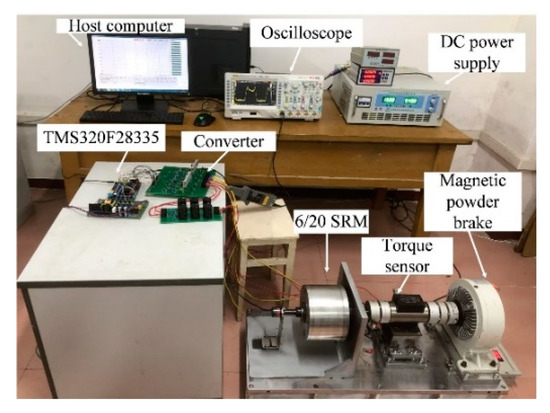
Figure 14.
Experimental platform of the SRM prototype.
The conventional exponential TSF and the proposed control strategy are compared and verified in order to verify the correctness of the proposed strategy. The load torque is set to 5 N·m, and the SRM operates at 500 r/min and 1000 r/min, respectively.
The waveforms of the current and torque of the SRM are shown in Figure 15a,b and Figure 16a,b when the SRM operates at 500 r/min. Figure 15 and Figure 16 are obtained from the conventional exponential TSF control strategy and the proposed control strategy, respectively. Comparing Figure 15b with Figure 16b, the torque ripple of the conventional exponential TSF control strategy is 30%, and the NUTSF control strategy is 19%. The results show that the NUTSF control strategy can reduce torque ripple effectively.
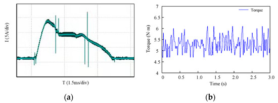
Figure 15.
Waveforms of conventional TSF at 500 r/min: (a) current; (b) torque.
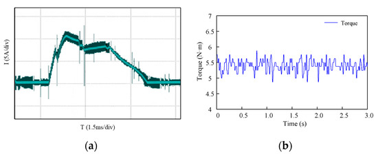
Figure 16.
Waveforms of NUTSF at 500 r/min: (a) current; (b) torque.
The waveforms are shown in Figure 17a,b and Figure 18a,b when the SRM operates at 1000 r/min. Figure 17 and Figure 18 are obtained from the conventional exponential TSF control strategy and the proposed control strategy, respectively. Comparing Figure 17b with Figure 18b, the torque ripple of the conventional exponential TSF control strategy is 70%, and the NUTSF control strategy is 22%. The results show that the proposed control strategy can effectively suppress torque ripple when the speed increases.
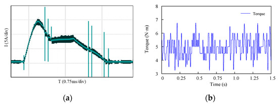
Figure 17.
Waveforms of conventional TSF at 1000 r/min: (a) current; (b) torque.
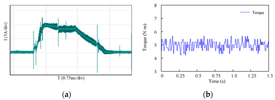
Figure 18.
Waveforms of NUTSF at 1000 r/min: (a) current; (b) torque.
According to Figure 15 and Figure 16, when the load torque is 5 N·m at 500 rpm, the torque ripples of the conventional TSF and the NUTSF are 30% and 19%, respectively, and the peak currents are 14 A and 12 A, respectively. Corresponding to the torque ripples of 21% and 15% and the peak currents of 15 A and 12 A in the simulation results of Figure 12. According to Figure 17 and Figure 18, when the load torque is 5 N·m at 1000 rpm, the torque ripples of the conventional TSF and the NUTSF are 70% and 22%, respectively, and the peak currents are 15 A and 10 A, respectively. Corresponding to the torque ripples of 62% and 18% and the peak currents of 15 A and 11 A in the simulation results of Figure 13. This indicates that the simulation results of peak current, current waveform and torque ripple are consistent with the experimental results under the same experimental conditions. The conventional TSF control strategy produces larger torque ripple owing to the weak ability of torque tracking. The control strategy proposed in this paper has good performance of tracking torque and suppressing torque ripple.
7. Conclusions
A non-unity torque sharing function at each sub-region is proposed in this article in order to reduce torque ripple. The causes of torque ripple are analyzed based on the characteristics of inductance. The two-phase exchange region is divided into region 1 and region 2. The NUTSF with inductance and torque characteristics is constructed in each sub-region, and adjusted online by changing the P1 th-power and P2 th-power. The simulation and prototype experiments on a three-phase 6/20 SRM verifies the proposed control strategy. The main contributions and advantages of the proposed NUTSF are summarized as follows:
- 1.
- The torque ripple at different speeds can be effectively reduced by using the proposed control strategy.
- 2.
- Different from the conventional TSF with a fixed shape, the NUTSF in the proposed control strategy can be adjusted online to accommodate different speeds, which helps expand the speed range.
- 3.
- The proposed control strategy is easier to realize and avoids the slow learning process of the intelligent algorithm model.
- 4.
- This proposed control strategy also has good reliability when the speed changes.
Author Contributions
W.C. and C.H. conceived and designed the experiments; W.C. performed the experiments with the help of J.X.; C.H. and W.C. analyzed the data; W.C. wrote the paper. All authors have read and agreed to the published version of the manuscript.
Funding
This research was funded by the National Natural Science Foundation of China (NSFC) (Grant No. 52167005).
Institutional Review Board Statement
Not applicable.
Informed Consent Statement
Not applicable.
Data Availability Statement
Not applicable.
Conflicts of Interest
The authors declare no conflict of interest.
References
- Diao, K.; Sun, X.; Lei, G.; Bramerdorfer, G.; Guo, Y.; Zhu, J. Robust Design Optimization of Switched Reluctance Motor Drive Systems Based on System-Level Sequential Taguchi Method. IEEE Trans. Energy Convers. 2021, 36, 3199–3207. [Google Scholar] [CrossRef]
- Hannoun, H.; Hilairet, M.; Marchand, C. High performance current control of a switched reluctance machine based on a gain-scheduling PI controller. Control. Eng. Pract. 2011, 19, 1377–1386. [Google Scholar] [CrossRef]
- Choi, Y.K.; Yoon, H.S.; Koh, C.S. Pole-Shape Optimization of a Switched-Reluctance Motor for Torque Ripple Reduction. IEEE Trans. Magn. 2007, 43, 1797–1800. [Google Scholar] [CrossRef]
- Kalaivani, L.; Subburaj, P.; Iruthayarajan, M.W. Speed control of switched reluctance motor with torque ripple reduction using non-dominated sorting genetic algorithm (NSGA-II). Int. J. Electr. Power Energy Syst. 2013, 53, 69–77. [Google Scholar] [CrossRef]
- Ling, X.; Tao, J.; Li, B.; Qin, C.; Liu, C. A Multi-Physics Modeling-Based Vibration Prediction Method for Switched Reluctance Motors. Appl. Sci. 2019, 19, 4544. [Google Scholar] [CrossRef] [Green Version]
- Husain, I.; Hossain, S.A. Modeling, Simulation, and control of switched reluctance motor drives. IEEE Trans. Ind. Electron. 2005, 52, 1625–1634. [Google Scholar] [CrossRef]
- Mademlis, C.; Kioskeridis, I. Performance optimization in switched reluctance motor drives with online commutation angle control. IEEE Trans. Energy Convers. 2003, 18, 448–457. [Google Scholar] [CrossRef]
- Ling, X.; Zhou, C.; Yang, L.; Zhang, J. Research on Influence of Switching Angle on the Vibration of Switched Reluctance Motor. Appl. Sci. 2022, 12, 4793. [Google Scholar] [CrossRef]
- Gan, C.; Wu, J.; Yang, S. Fault Diagnosis of Power Converter for Switched Reluctance Motor Based on Discrete Degree Analysis of Wavelet Packet Energy. In Proceedings of the 2013 International Conference on Electrical Machines and Systems (ICEMS), Busan, Korea, 26–29 October 2013; pp. 768–772. [Google Scholar]
- Bayless, J.; Kurihara, N.; Sugimoto, H.; Chiba, A. Acoustic Noise Reduction of Switched Reluctance Motor with Reduced RMS Current and Enhanced Efficiency. IEEE Trans. Energy Convers. 2016, 31, 627–636. [Google Scholar] [CrossRef]
- Sahoo, S.K.; Dasgupta, S.; Panda, S.K.; Xu, J.X. A Lyapunov Function-Based Robust Direct Torque Controller for a Switched Reluctance Motor Drive System. IEEE Trans. Power Electron. 2012, 27, 555–564. [Google Scholar] [CrossRef]
- Pires, V.F.; Amaral, T.G.; Cordeiro, A.; Foito, D.; Pires, A.J.; Martins, J.F. Fault-Tolerant SRM Drive with a Diagnosis Method Based on the Entropy Feature Approach. Appl. Sci. 2020, 10, 3516. [Google Scholar] [CrossRef]
- Xue, X.D.; Cheng, K.W.E.; Ho, S.L. Optimization and Evaluation of Torque-Sharing Functions for Torque Ripple Minimization in Switched Reluctance Motor Drives. IEEE Trans. Power Electron. 2009, 24, 2076–2090. [Google Scholar] [CrossRef] [Green Version]
- Rana, A.K.; Teja, A.V.R. A Mathematical Torque Ripple Minimization Technique Based on a Nonlinear Modulating Factor for Switched Reluctance Motor Drives. IEEE Trans. Ind. Electron. 2022, 69, 1356–1366. [Google Scholar] [CrossRef]
- Ye, W.; Ma, Q.; Zhang, P. Improvement of the Torque-Speed Performance and Drive Efficiency in an SRM Using an Optimal Torque Sharing Function. Appl. Sci. 2018, 8, 720. [Google Scholar] [CrossRef] [Green Version]
- Vujicic, V.P. Minimization of Torque Ripple and Copper Losses in Switched Reluctance Drive. IEEE Trans. Power Electron. 2012, 1, 388–399. [Google Scholar] [CrossRef]
- Ye, J.; Bilgin, B.; Emadi, A. An Offline Torque Sharing Function for Torque Ripple Reduction in Switched Reluctance Motor Drives. IEEE Trans. Energy Convers. 2015, 2, 726–735. [Google Scholar] [CrossRef]
- Ye, J.; Bilgin, B.; Emadi, A. An Extended-Speed Low-Ripple Torque Control of Switched Reluctance Motor Drives. IEEE Trans. Power Electron. 2015, 3, 1457–1470. [Google Scholar] [CrossRef]
- Sun, Q.; Wu, J.; Gan, C.; Hu, Y.; Si, J. OCTSF for torque ripple minimization in SRMs. IET Power Electron. 2016, 14, 2741–2750. [Google Scholar] [CrossRef]
- Ahmad, S.S.; Narayanan, G. Predictive Control Based Constant Current Injection Scheme for Characterization of Switched Reluctance Machine. IEEE Trans. Ind. Appl. 2018, 54, 3383–3392. [Google Scholar] [CrossRef]
- Mehta, S.; Kabir, M.A.; Husain, I. Extended Speed Current Profiling Algorithm for Low Torque Ripple SRM Using Model Predictive Control. In Proceedings of the 2018 IEEE Energy Conversion Congress and Exposition (ECCE), Portland, OR, USA, 23–27 September 2018; pp. 4558–4563. [Google Scholar]
- Song, S.; Hei, R.; Ma, R.; Liu, W. Model Predictive Control of Switched Reluctance Starter/Generator with Torque Sharing and Compensation. IEEE Trans. Transp. Electrif. 2020, 6, 1519–1527. [Google Scholar] [CrossRef]
- Xu, A.; Shang, C.; Chen, J.; Zhu, J.; Han, L. A New Control Method Based on DTC and MPC to Reduce Torque Ripple in SRM. IEEE Access 2019, 7, 68584–68593. [Google Scholar] [CrossRef]
- Ling, X.; Zhou, C.; Yang, L.; Zhang, J. Torque Ripple Suppression Method of Switched Reluctance Motor Based on an Improved Torque Distribution Function. Electronics 2022, 11, 1552. [Google Scholar] [CrossRef]
- Li, H.; Bilgin, B.; Emadi, A. An Improved Torque Sharing Function for Torque Ripple Reduction in Switched Reluctance Machines. IEEE Trans. Power Electron. 2019, 34, 1635–1644. [Google Scholar] [CrossRef]
- Ding Hong, Y.; Dean, Z.; Ying Xin, J. A Research for Angle Optimization of the SRM Used in Electric Actuator of Valves. Appl. Mech. Mater. 2013, 404, 586–591. [Google Scholar]
- Tao, T.; Gan, S.; Wang, J.; Song, X.; Zhang, J.; Sun, Z. Angle position control of fuzzy algorithm with variable scale factor for SRM. ICIC Express Lett. 2017, 11, 789–797. [Google Scholar]
- Cai, J.; Jin, R. Reversible drive system of switched reluctance motor based on DSP controller. J. Zhejiang Univ. Eng. Sci. 2006, 40, 1019–1026. [Google Scholar]
- Blaabjerg, F.; Kjaer, P.C.; Rasmussen, P.O.; Cossar, C. Improved Digital Current Control Methods in Switched Reluctance Motor Drives. IEEE Trans. Power Electron. 1999, 14, 563–572. [Google Scholar] [CrossRef]
- Saha, N.; Panda, A.K.; Panda, S. Speed control with torque ripple reduction of switched reluctance motor by many optimizing liaison technique. J. Electr. Syst. Inf. Technol. 2018, 5, 829–842. [Google Scholar] [CrossRef]
- Alharkan, H.; Saadatmand, S.; Ferdowsi, M.; Shamsi, P. Optimal Tracking Current Control of Switched Reluctance Motor Drives Using Reinforcement Q-Learning Scheduling. IEEE Access 2021, 9, 9926–9936. [Google Scholar] [CrossRef]
Publisher’s Note: MDPI stays neutral with regard to jurisdictional claims in published maps and institutional affiliations. |
© 2022 by the authors. Licensee MDPI, Basel, Switzerland. This article is an open access article distributed under the terms and conditions of the Creative Commons Attribution (CC BY) license (https://creativecommons.org/licenses/by/4.0/).