
Additive Manufacturing Potentials of High Performance Ferritic (HiperFer) Steels


Abstract
:Featured Application
Abstract
1. Introduction
2. Materials and Methods
2.1. Laves-Phase-Strengthened Ferritic HiperFer Steel
2.2. LMD-Manufactured HiperFerAM
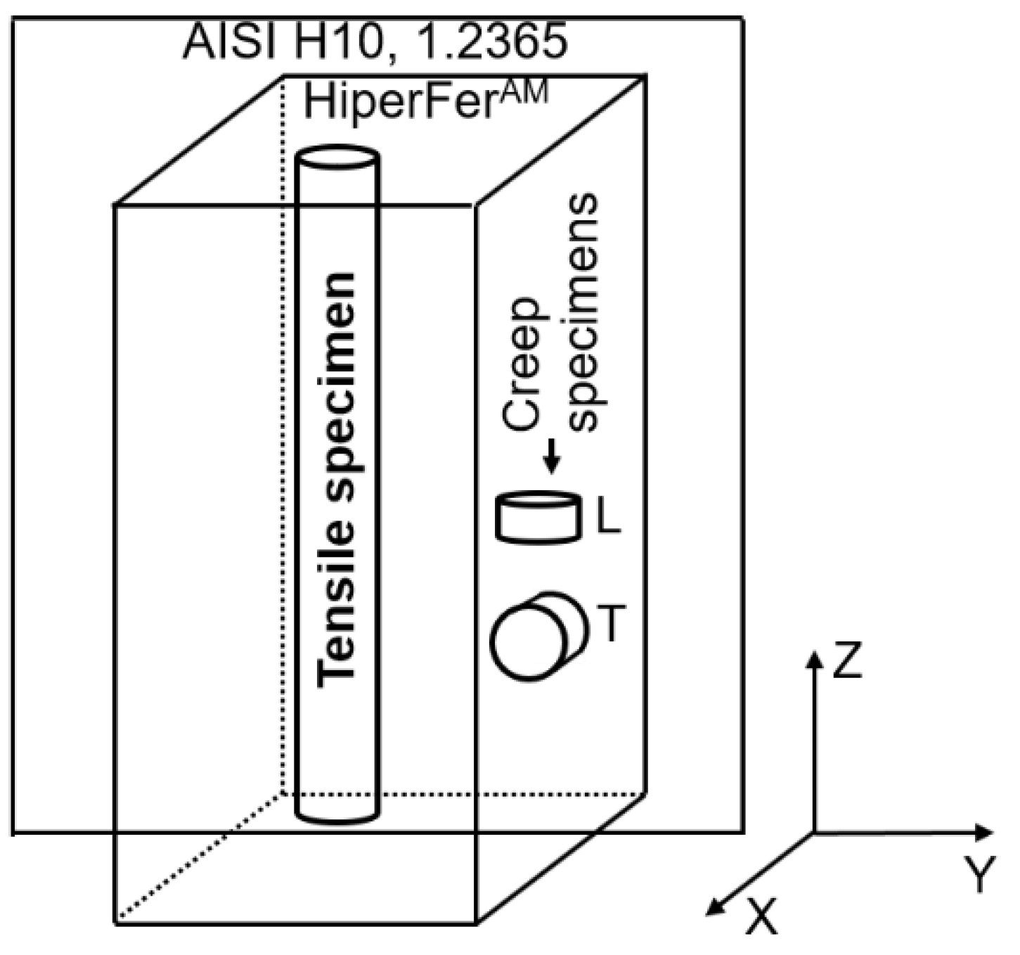
2.3. Mechanical Testing
2.4. Microstructural Investigation
3. Results and Discussion
4. Conclusions
5. Outlook
Author Contributions
Funding
Institutional Review Board Statement
Informed Consent Statement
Data Availability Statement
Acknowledgments
Conflicts of Interest
References
- Khorasani, M.; Ghasemi, A.; Leary, M.; Sharabian, E.; Cordova, L.; Gibson, I.; Downing, D.; Bateman, S.; Brandt, M.; Rolfe, B. The effect of absorption ratio on meltpool features in laser-based powder bed fusion of IN718. Opt. Laser Technol. 2022, 153, 108263. [Google Scholar] [CrossRef]
- Zhao, Y.; Koizumi, Y.; Aoyagi, K.; Yamanaka, K.; Chiba, A. Thermal properties of powder beds in energy absorption and heat transfer during additive manufacturing with electron beam. Powder Technol. 2021, 381, 44–54. [Google Scholar] [CrossRef]
- Khan, H.M.; Waqar, S.; Koç, E. Evolution of temperature and residual stress behavior in selective laser melting of 316L stainless steel across a cooling channel. Rapid Prototyp. J. 2022, 28, 1272–1283. [Google Scholar] [CrossRef]
- Singh, A.K.; Mundada, Y.; Bajaj, P.; Wilms, M.B.; Patil, J.; Kumar Mishra, S.; Jägle, E.A.; Arora, A. Investigation of temperature distribution and solidification morphology in multilayered directed energy deposition of Al-0.5Sc-0.5Si alloy. Int. J. Heat Mass Transf. 2022, 186, 122492. [Google Scholar] [CrossRef]
- Nespoli, A.; Bennato, N.; Villa, E.; Passaretti, F. Study of anisotropy through microscopy, internal friction and electrical resistivity measurements of Ti-6Al-4V samples fabricated by selective laser melting. Rapid Prototyp. J. 2022, 28, 1060–1075. [Google Scholar] [CrossRef]
- Kürnsteiner, P.; Bajaj, P.; Gupta, A.; Wilms, M.B.; Weisheit, A.; Li, X.; Leinenbach, C.; Gault, B.; Jägle, E.A.; Raabe, D. Control of thermally stable core-shell nano-precipitates in additively manufactured Al-Sc-Zr alloys. Addit. Manuf. 2020, 32, 100910. [Google Scholar] [CrossRef]
- Kürnsteiner, P.; Wilms, M.B.; Weisheit, A.; Gault, B.; Jägle, E.A.; Raabe, D. High-strength Damascus steel by additive manufacturing. Nature 2020, 582, 515–519. [Google Scholar] [CrossRef]
- Kürnsteiner, P.; Wilms, M.B.; Weisheit, A.; Barriobero-Vila, P.; Jägle, E.A.; Raabe, D. Massive nanoprecipitation in an Fe-19Ni-xAl maraging steel triggered by the intrinsic heat treatment during laser metal deposition. Acta Mater. 2017, 129, 52–60. [Google Scholar] [CrossRef]
- Fischer, T.; Kuhn, B.; Rieck, D.; Schulz, A.; Trieglaff, R.; Wilms, M.B. Fatigue Cracking of Additively Manufactured Materials—Process and Material Perspectives. Appl. Sci. 2020, 10, 5556. [Google Scholar] [CrossRef]
- Barriobero-Vila, P.; Artzt, K.; Stark, A.; Schell, N.; Siggel, M.; Gussone, J.; Kleinert, J.; Kitsche, W.; Requena, G.; Haubrich, J. Mapping the geometry of Ti-6Al-4V: From martensite decomposition to localized spheroidization during selective laser melting. Scr. Mater. 2020, 182, 48–52. [Google Scholar] [CrossRef]
- Rittinghaus, S.-K.; Amr, A.; Hecht, U. Intrinsic heat treatment of an additively manufactured medium entropy AlCrFe2Ni2-alloy. Met. Mater. Int. 2022. [Google Scholar] [CrossRef]
- Yakout, M.; Elbestawi, M.A.; Veldhuis, S.C.; Nangle-Smith, S. Influence of thermal properties on residual stresses in SLM of aerospace alloys. Rapid Prototyp. J. 2019, 26, 213–222. [Google Scholar] [CrossRef]
- Mishrunova, T.; Artzt, K.; Haubrich, J.; Requena, G.; Bruno, G. Exploring the correlation between subsurface residual stresses and manufacturing parameters in laser powder bed fused Ti-6Al-4V. Metals 2019, 9, 261. [Google Scholar] [CrossRef] [Green Version]
- Piscopo, G.; Salmi, A.; Atzeni, E. Influence of high-productivity process parameters on the surface quality and residual stress state of AISI 316L components produced by directed energy deposition. J. Mater. Eng. Perform. 2021, 30, 6691–6702. [Google Scholar] [CrossRef]
- Giganto, S.; Martinzez-Pellitero, S.; Cuesta, E.; Zapico, P.; Barreiro, J. Proposal of design rules for improving the accuracy of selective laser melting (SLM) manufacturing using benchmarks parts. Rapid Prototyp. J. 2022, 28, 1129–1143. [Google Scholar] [CrossRef]
- Kies, F.; Wilms, M.B.; Pirch, N.; Pradeep, K.G.; Schleifenbaum, J.H.; Haase, C. Defect formation and prevention in directed energy deposition of high-manganese steels and the effect on mechanical properties. Mater. Sci. Eng. A 2020, 772, 138688. [Google Scholar] [CrossRef]
- Ikeda, T.; Yonehara, M.; Ikeshoji, T.-T.; Nobuki, T.; Hatate, M.; Kuwabara, K.; Otsubo, Y.; Kyogoku, H. Influences of process parameters on the microstructure and mechanical properties of CoCrFeNiTi based high-entropy alloy in a laser powder bed fusion process. Crystals 2021, 11, 549. [Google Scholar] [CrossRef]
- Linares, J.-M.; Chaves-Jacob, J.; Lopez, Q.; Sprauel, J.-M. Fatigue life optimization for 17-4Ph steel produced by selective laser melting. Rapid Prototyp. J. 2022, 28, 1182–1192. [Google Scholar] [CrossRef]
- Bajaj, P.; Hariharan, A.; Kini, A.; Kürnsteiner, P.; Raabe, D.; Jägle, E.A. Steels in additive manufacturing: A review of their microstructure and properties. Mater. Sci. Eng. A 2020, 772, 138633. [Google Scholar] [CrossRef]
- Wolff, S.; Lee, T.; Faierson, E.; Ehmann, K.; Cao, J. Anisotropic properties of directed energy deposition (DED)-processed Ti–6Al–4V. J. Manuf. Processes 2016, 24, 397–405. [Google Scholar] [CrossRef] [Green Version]
- Davies, C.M.; Thomlinson, H.; Hooper, P.A. Fatigue Crack Initiation and Growth Behaviour of 316L Stainless Steel Manufactured Through Selective Laser Melting. In Proceedings of the ASME 2017 Pressure Vessels and Piping Conference, Volume 6A: Materials and Fabrication, Waikoloa, HI, USA, 26 October 2017. [Google Scholar] [CrossRef]
- Yadollahi, A.; Shamsaei, N.; Thompson, S.M.; Elwany, A.; Bian, L. Effects of building orientation and heat treatment on fatigue behavior of selective laser melted 17-4 PH stainless steel. Int. J. Fatigue 2017, 94, 218–235. [Google Scholar] [CrossRef]
- Zhang, M.; Sun, C.-N.; Zhang, X.; Wei, J.; Hardacre, D.; Li, H. High cycle fatigue and ratcheting interaction of laser powder bed fusion stainless steel 316L: Fracture behaviour and stress-based modelling. Int. J. Fatigue 2019, 121, 252–264. [Google Scholar] [CrossRef]
- Blinn, B.; Klein, M.; Gläßner, C.; Smaga, M.; Aurich, J.C.; Beck, T. An investigation of the microstructure and fatigue behavior of additively manufactured AISI 316L stainless steel with regard to the influence of heat treatment. Metals 2018, 8, 220. [Google Scholar] [CrossRef] [Green Version]
- Kuhn, B.; Talik, M. HiperFer—High Performance Ferritic Steels. In Proceedings of the 10th Liège Conference on Materials for Advanced Power Engineering; Schriften des Forschungszentrums Jülich Reihe Energie & Umwelt/Energy & Environment: Liège, Belgium, 2014; Volume 234, pp. 264–273. ISBN 978-3-95806-000-5. (In Belgium) [Google Scholar]
- Kuhn, B.; Talik, M.; Niewolak, L.; Zurek, J.; Hattendorf, H.; Ennis, P.J.; Quadakkers, W.J.; Beck, T.; Singheiser, L. Development of High Chromium Ferritic Steels Strengthened by Intermetallic Phases. Mater. Sci. Eng. A 2014, 594, 372–380. [Google Scholar] [CrossRef]
- Kuhn, B.; Lopez Barrilao, J.; Fischer, T. “Reactive” microstructure, the key to cost-effective, fatigue-resistant high temperature structural materials. In Proceedings of the Joint EPRI-123HiMAT International Conference on Advances in High Temperature Materials, Nagasaki, Japan, 21–24 October 2019; ISBN 13 987-1-62708-271-6. [Google Scholar]
- Hsiao, Z.W.; Kuhn, B.; Yang, S.M.; Yang, L.C.; Huang, S.Y.; Singheiser, L.; Kuo, J.C.; Lin, D.Y. The Influence of Deformation on the Precipitation Behavior of a Ferritic Stainless Steel. In Proceedings of the 10th Liège Conference on Materials for Advanced Power Engineering, Schriften des Forschungszentrums Jülich/Energy & Environment, Liege, Belgium, 14–17 September 2014; Lecomte-Beckers, J., Dedry, O., Oackey, J., Kuhn, B., Eds.; Forschungszentrum Jülich GmbH Zentralbibliothek: Julich, Germany, 2014; Volume 94, pp. 349–358. [Google Scholar]
- Pöpperlová, J.; Fan, X.; Kuhn, B.; Bleck, W.; Krupp, U. Impact of Tungsten on Thermomechanically Induced Precipitation of Laves Phase in High Performance Ferritic (HiperFer) Stainless Steels. Appl. Sci. 2020, 10, 4472. [Google Scholar] [CrossRef]
- Fan, X.; Kuhn, B.; Pöpperlová, J.; Bleck, W.; Krupp, U. Thermomechanically Induced Precipitation in High Performance Ferritic (HiperFer) Stainless Steels. Appl. Sci. 2020, 10, 5713. [Google Scholar] [CrossRef]
- Fan, X.; Kuhn, B.; Pöpperlová, J.; Bleck, W.; Krupp, U. Compositional Optimization of High-Performance Ferritic (HiperFer) Steels—Effect of Niobium and Tungsten Content. Metals 2020, 10, 1300. [Google Scholar] [CrossRef]
- Kuhn, B.; Talik, M.; Fischer, T.; Fan, X.; Yamamoto, Y.; Lopez Barrilao, J. Science and technology of high performance ferritic (HiperFer) Stainless Steels. Metals 2020, 10, 463. [Google Scholar] [CrossRef] [Green Version]
- Kuhn, B.; Barrilao, J.L.; Fischer, T. Impact of Thermomechanical Fatigue on Microstructure Evolution of a Ferritic-Martensitic 9 Cr and a Ferritic, Stainless 22 Cr Steel. Appl. Sci. 2020, 10, 6338. [Google Scholar] [CrossRef]
- Blinn, B.; Görzen, D.; Fischer, T.; Kuhn, B.; Beck, T. Analysis of the Thermomechanical Fatigue Behavior of Fully Ferritic High Chromium Steel Crofer®22 H with Cyclic Indentation Testing. Appl. Sci. 2020, 10, 6461. [Google Scholar] [CrossRef]
- Froitzheim, J.; Meier, G.H.; Niewolak, L.; Ennis, P.J.; Hattendorf, H.; Singheiser, L. Development of high strength ferritic steel for interconnect application in SOFCs. J. Power Sources 2008, 178, 163–173. [Google Scholar] [CrossRef]
- National Board Inspection Code (NBIC). Part-3 National Board Inspection Code; ASME Press: New York, NY, USA, 2011. [Google Scholar]
- ASME BPV Code. Section III, Division 1: Rules for Construction of Nuclear Facility Components; ASME Press: New York, NY, USA, 2019. [Google Scholar]
- Welding Technology Institute of Australis. (WTIA) publication, TGN-PE-02, Temper Bead Welding, Rev0,1; Welding Technology Institute of Australia: Pymble, Australia, 2006. [Google Scholar]
- ASME BPVC. Section IX-Welding, Brazing, and Fusing Qualifications; ASME Press: New York, NY, USA, 2015. [Google Scholar]
- Talik, M.; Kuhn, B. High Temperature Mechanical Properties of a 17wt%Cr High Performance Ferritic (HiperFer) Steel Strengthened by Intermetallic Laves Phase Particles. In Proceedings of the 9th International Charles Parsons Turbine and Generator Conference, Loughborough, UK, 15–17 September 2015. [Google Scholar]
- DIN EN 10002-5:1992-02; Zugversuch, Prüfverfahren bei erhöhter Temperatur, DIN Deutsches Institut für Normung e. V. Beuth Verlag GmbH: Berlin, Germany, 1991.
- DIN EN ISO 6892-2:2011-05; Metallische Werkstoffe-Zugversuch-Teil 2: Prüfverfahren bei erhöhter Temperatur, DIN Deutsches Institut für Normung e. V. Beuth Verlag GmbH: Berlin, Germany, 2011.
- DIN EN ISO 6507-1:2018; Metallic Materials-Vickers Hardness Test-Part 1: Test method (ISO 6507-1:2018). Beuth Verlag GmbH: Berlin, Germany, 2018.
- Barrilao, J.L.; Kuhn, B.; Wessel, E. Identification, size classification and evolution of Laves phase precipitates in high chromium, fully ferritic steels. Micron 2017, 101, 221–231. [Google Scholar] [CrossRef] [PubMed]
- Sim, G.M.; Ahn, J.C.; Hong, S.C.; Lee, K.J.; Lee, K.S. Effect of Nb precipitate coarsening on the high temperature strength in Nb containing ferritic stainless steels. Mater. Sci. Eng. A 2005, 396, 159–165. [Google Scholar] [CrossRef]
- Hosoi, Y.; Wade, N.; Kunimitsu, S.; Urita, T. Precipitation behavior of Laves phase and its effect on toughness of 9Cr-2Mo Ferritic-martensitic steel. J. Nucl. Mater. 1986, 141, 461–467. [Google Scholar] [CrossRef]
- Suo, J.; Peng, Z.; Yang, H.; Chai, G.; Yu, M. Formation of Laves Phase in Sanicro 25 Austenitic Steel during Creep-Rupture Test at 700 °C. Metallogr. Microstruct. Anal. 2019, 2, 281–286. [Google Scholar] [CrossRef]
- Aghajani, A.; Richter, F.; Somsen, C.; Fries, S.G.; Steinbach, I.; Eggeler, G. On the formation and growth of Mo-rich Laves phase particles during long-term creep of a 12% chromium tempered martensite ferritic steel. Scr. Mater. 2009, 61, 1068–1071. [Google Scholar] [CrossRef]
- Guo, J.T.; Zhou, L.Z. The Effect of Phosphorus, Sulphur and Silicon on Segregation, Solidification and Mechanical Properties of Cast Alloy 718. In Proceedings of the 8th International Symposium on Superalloys, Seven Springs Mountain Resort, Champion, PA, USA, 22–26 September 1996; pp. 451–458. [Google Scholar]
- Kato, Y.; Ito, M.; Kato, Y.; Furukimi, O. Effect of Si on Precipitation Behavior of Nb-Laves Phase and Amount of Nb in Solid Solution at Elevated Temperature in High Purity 17%Cr-0.5%Nb Steels. Mater. Trans. 2010, 51, 1531–1535. [Google Scholar] [CrossRef] [Green Version]
- Niewolak, L.; Savenko, A.; Grüner, D.; Hattendorf, H.; Breuer, U.; Quadakkers, W.J. Temperature Dependence of Laves Phase Composition in Nb, W and Si-Alloyed High Chromium Ferritic Steels for SOFC Interconnect Applications. JPEDAV 2015, 36, 471–484. [Google Scholar] [CrossRef]
- Vo, N.Q.; Liebscher, C.H.; Rawlings, M.J.S.; Asta, M.; Dunand, D.C. Creep properties and microstructure of a precipitation-strengthened ferritic Fe–Al–Ni–Cr alloy. Acta Mater. 2014, 71, 89–99. [Google Scholar] [CrossRef]
- Fan, X. Optimization of Laves Phase Strengthened High Performance Ferritic Stainless Steels. Ph.D. Thesis, RWTH Aachen, Aachen, Germany, 2020. Available online: https://publications.rwth-aachen.de/record/792517/files/792517.pdf (accessed on 19 May 2022). [CrossRef]
- Kuhn, B.; Fischer, T.; Fan, X.; Talik, M.; Aarab, F.; Yamamoto, Y. HiperFer-Weiterentwicklungs-Und Anwendungspotenziale. In Proceedings of the 43th FVWHT Vortragsveranstaltung Langzeitverhalten Warmfester Stähle und Hochtemperaturwerkstoffe, Online, 27 November 2020; p. 43. [Google Scholar]
- Kuhn, B.; Talik, M.; Lopez Barrilao, J.; Singheiser, L. Microstructure stability of ferritic-martensitic, austenitic and fully ferritic steels under fluctuating loading conditions. In Proceedings of the 1st 123rd HiMat Conference, Sapporo, Japan, 29 June–3 July 2015. [Google Scholar]
- Zhang, Q.; Zhu, Y.; Gao, X.; Wu, Y.; Hutchinson, C. Training high-strength aluminum alloys to withstand fatigue. Nat Commun. 2020, 11, 5198. [Google Scholar] [CrossRef]
- Lesuer, D.R.; Syn, C.K.; Sherby, O.D. An Evaluation of Power Law Breakdown in Metals, Alloys, Dispersion Hardened Materials and Compounds; Lawrence Livermore National Lab.(LLNL): Livermore, CA, USA, 1999. [Google Scholar]


| 22 A | C 0.004 Nb <0.01 | S < 0.001 W - | N 0.002 Cu - | Cr 22.8 Fe Balance | Ni - P - | Mn 0.44 Al 0.013 | Si 0.02 Mg - | Mo - Co - | Ti 0.06 La - |
|---|---|---|---|---|---|---|---|---|---|
| HiperFer 17Cr2 * | C | S | N | Cr | Ni | Mn | Si | Mo | Ti |
| <0.003 | <0.001 | <0.003 | 17–18 | - | 0.2–0.5 | 0.2–0.3 | - | - | |
| Nb | W | Cu | Fe | P | Al | Mg | Co | La | |
| 0.5-0.6 | 2.4-2.6 | - | Balance | - | - | - | - | - | |
| HiperFerAM | C | S | N | Cr | Ni | Mn | Si | Mo | Ti |
| 0.0033 | <0.0008 | 0.0017 | 19.152 | - | 0.365 | 1 | - | 0.05 | |
| Nb | W | Cu | Fe | P | Al | Mg | Co | La | |
| 1.5 | 2 | - | Balance | - | - | - | - | - |
| Process Parameter | Low Power Density (“LPD”) | High Power Density (“HPD”) |
|---|---|---|
| Area-specific laser power | 195 Wmm−2 | 1050 Wmm−2 |
| Feed speed | 400 mm/min | 1500 mm/min |
| Laser power | 1375 W | 360 W |
| Powder mass flow rate | 11.3 g/min | 2.4 g/min |
| Track offset | 2.3 mm | 0.35 mm |
| Height offset | 1.4 mm | 0.3 mm |
| Beam diameter | 3 mm | 0.66 mm |
| Deposition strategy | Unidirectional | Unidirectional |
| Nozzle type | 3-jet nozzle | 3-jet nozzle |
| Shielding gas | Argon | Argon |
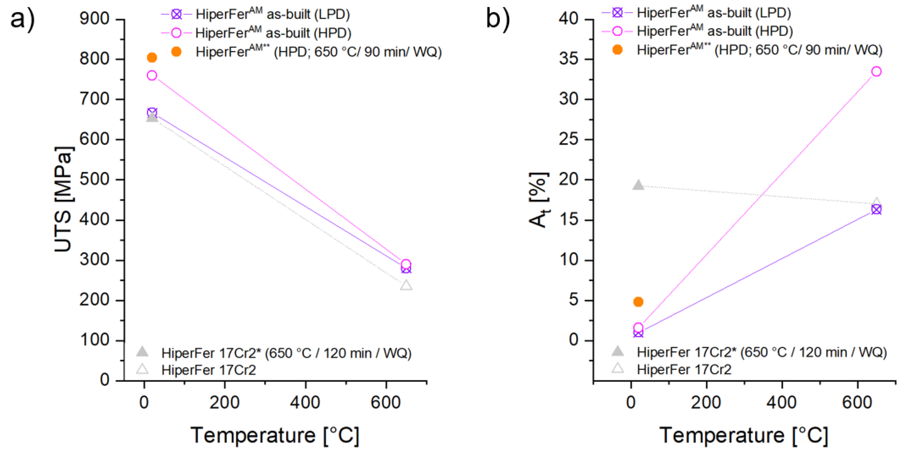
| Material | Heat-Treatment State | Area-Specific Laser Power (Wmm−2) | Test Temperature (°C) | UTS (MPa) | At (%) |
|---|---|---|---|---|---|
| HiperFer 17Cr2 | 650 °C/120 min | - | 20 | 653 | 19.2 |
| HiperFer 17Cr2 | - | - | 650 | 235 | 17 |
| HiperFerAM | As-built | 1050 (HPD) | 20 | 760 | 1.6 |
| HiperFerAM | As-built | 195 (LPD) | 20 | 667 | 1 |
| HiperFerAM | 650 °C/90 min | 1050 (HPD) | 20 | 804 | 4.8 |
| HiperFerAM | As-built | 1050 (HPD) | 650 | 290 | 33.5 |
| HiperFerAM | As-built | 195 (LPD) | 650 | 280 | 16.3 |
| Material | Hardness, As-Built State (HV1) | Hardness, After Creep Compression Test (HV1) | ||||||
|---|---|---|---|---|---|---|---|---|
| Mean | Min. | Max. | Range | Mean | Min. | Max. | Range | |
| HiperFerAM LPD-L | 199 | 193 | 209 | 16 | 211 | 197 | 222 | 25 |
| HiperFerAM HPD-L | 226 | 217 | 233 | 16 | 248 | 239 | 252 | 13 |
| HiperFerAM LPD-Q | 196 | 186 | 201 | 15 | 218 | 206 | 226 | 20 |
| HiperFerAM HPD-Q | 233 | 217 | 244 | 27 | 252 | 240 | 272 | 32 |
Publisher’s Note: MDPI stays neutral with regard to jurisdictional claims in published maps and institutional affiliations. |
© 2022 by the authors. Licensee MDPI, Basel, Switzerland. This article is an open access article distributed under the terms and conditions of the Creative Commons Attribution (CC BY) license (https://creativecommons.org/licenses/by/4.0/).
Share and Cite
Fischer, T.; Kuhn, B.; Fan, X.; Wilms, M.B. Additive Manufacturing Potentials of High Performance Ferritic (HiperFer) Steels. Appl. Sci. 2022, 12, 7234. https://doi.org/10.3390/app12147234
Fischer T, Kuhn B, Fan X, Wilms MB. Additive Manufacturing Potentials of High Performance Ferritic (HiperFer) Steels. Applied Sciences. 2022; 12(14):7234. https://doi.org/10.3390/app12147234
Chicago/Turabian StyleFischer, Torsten, Bernd Kuhn, Xiuru Fan, and Markus Benjamin Wilms. 2022. "Additive Manufacturing Potentials of High Performance Ferritic (HiperFer) Steels" Applied Sciences 12, no. 14: 7234. https://doi.org/10.3390/app12147234
APA StyleFischer, T., Kuhn, B., Fan, X., & Wilms, M. B. (2022). Additive Manufacturing Potentials of High Performance Ferritic (HiperFer) Steels. Applied Sciences, 12(14), 7234. https://doi.org/10.3390/app12147234