
An Innovative Process Design Model for Machined Surface Error Distribution Consistency in High-Efficiency Milling

Abstract
:Featured Application
Abstract
1. Introduction
2. Calculation Model of the Machined Surface Error under Vibration
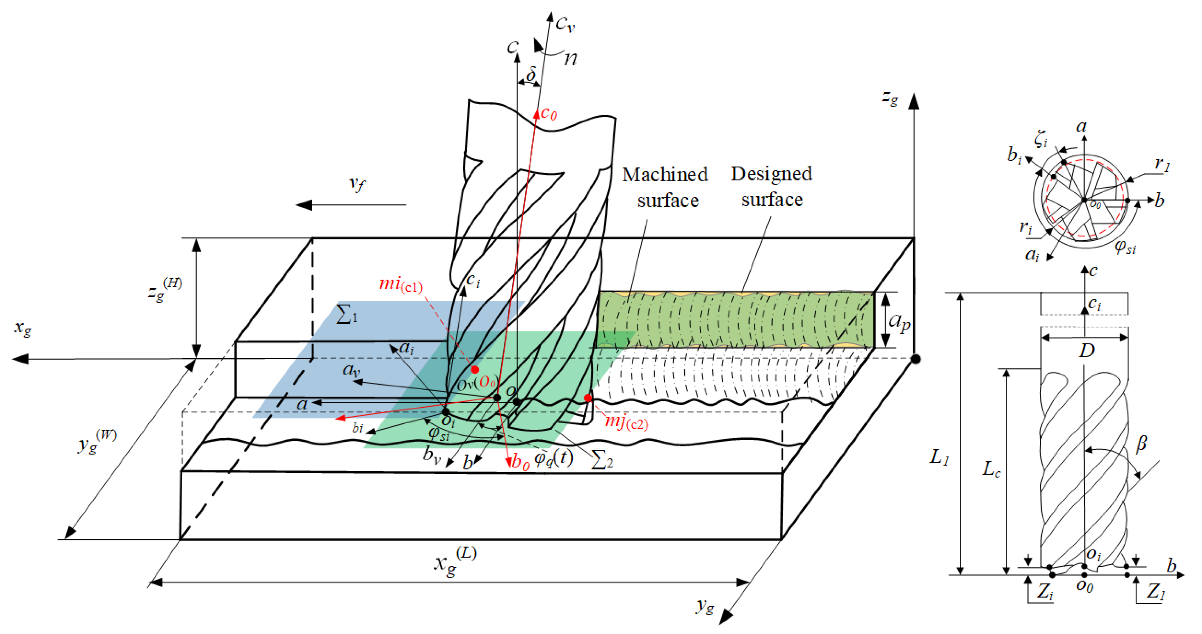
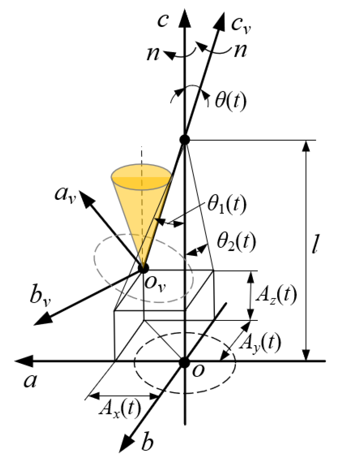
2.1. Cutting Trajectory of the Milling Cutter under Vibration
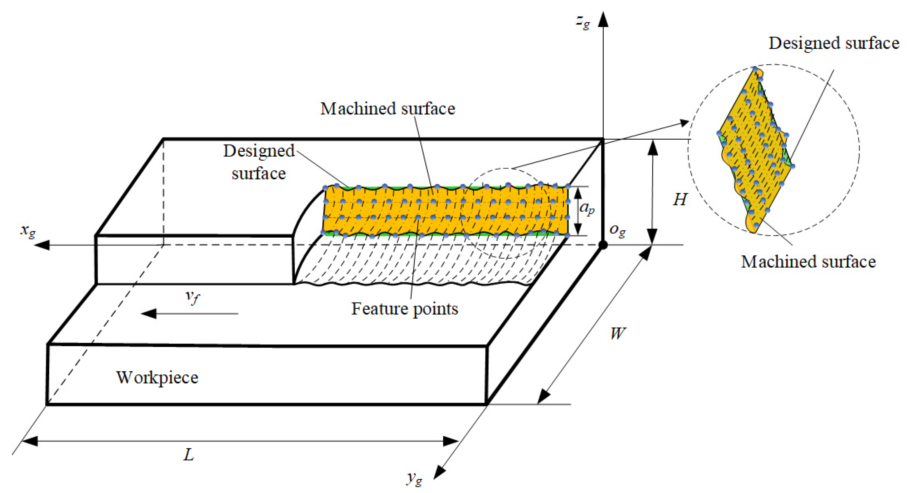
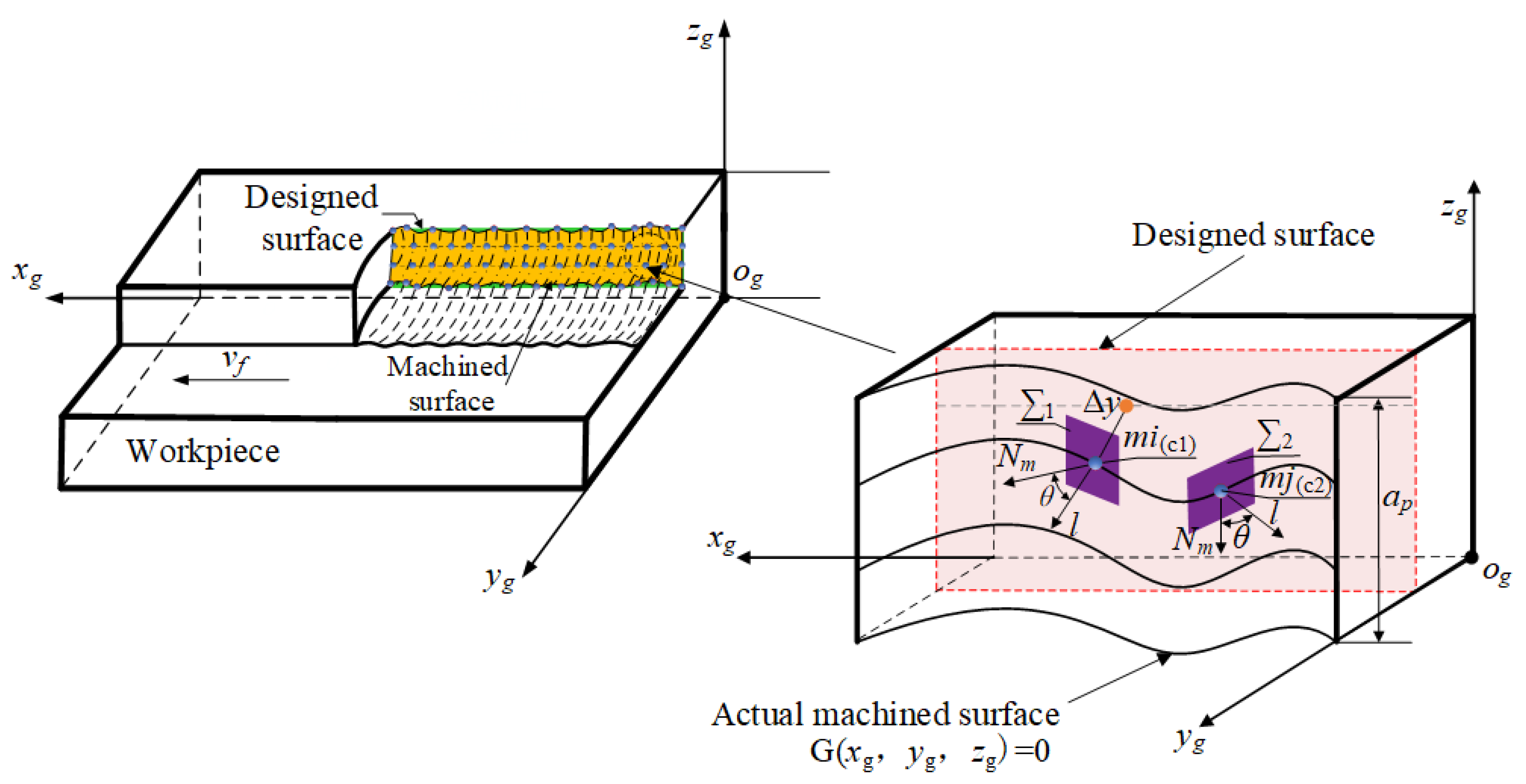
2.2. Calculation Model of the Machined Surface Error under Vibration
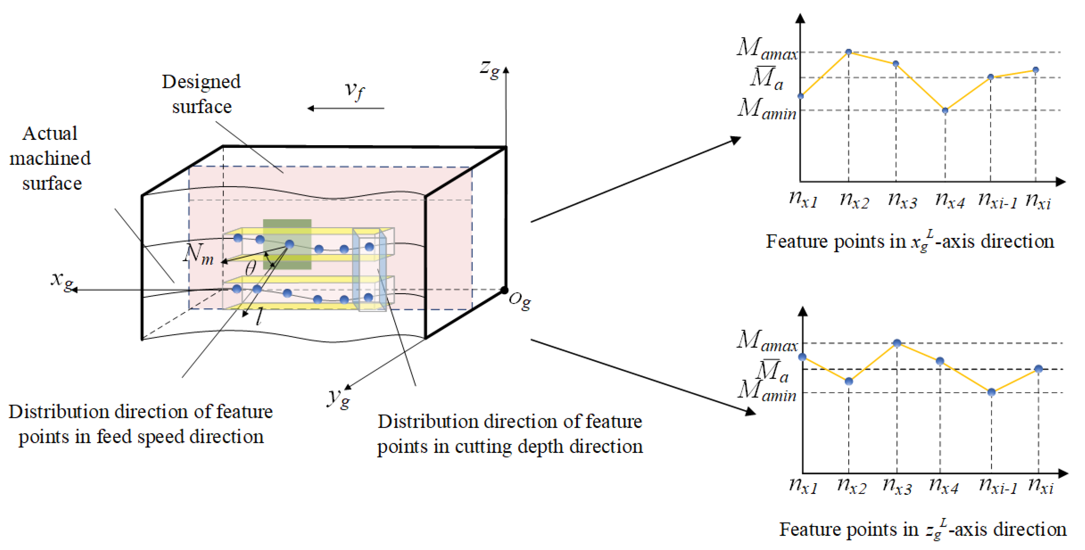
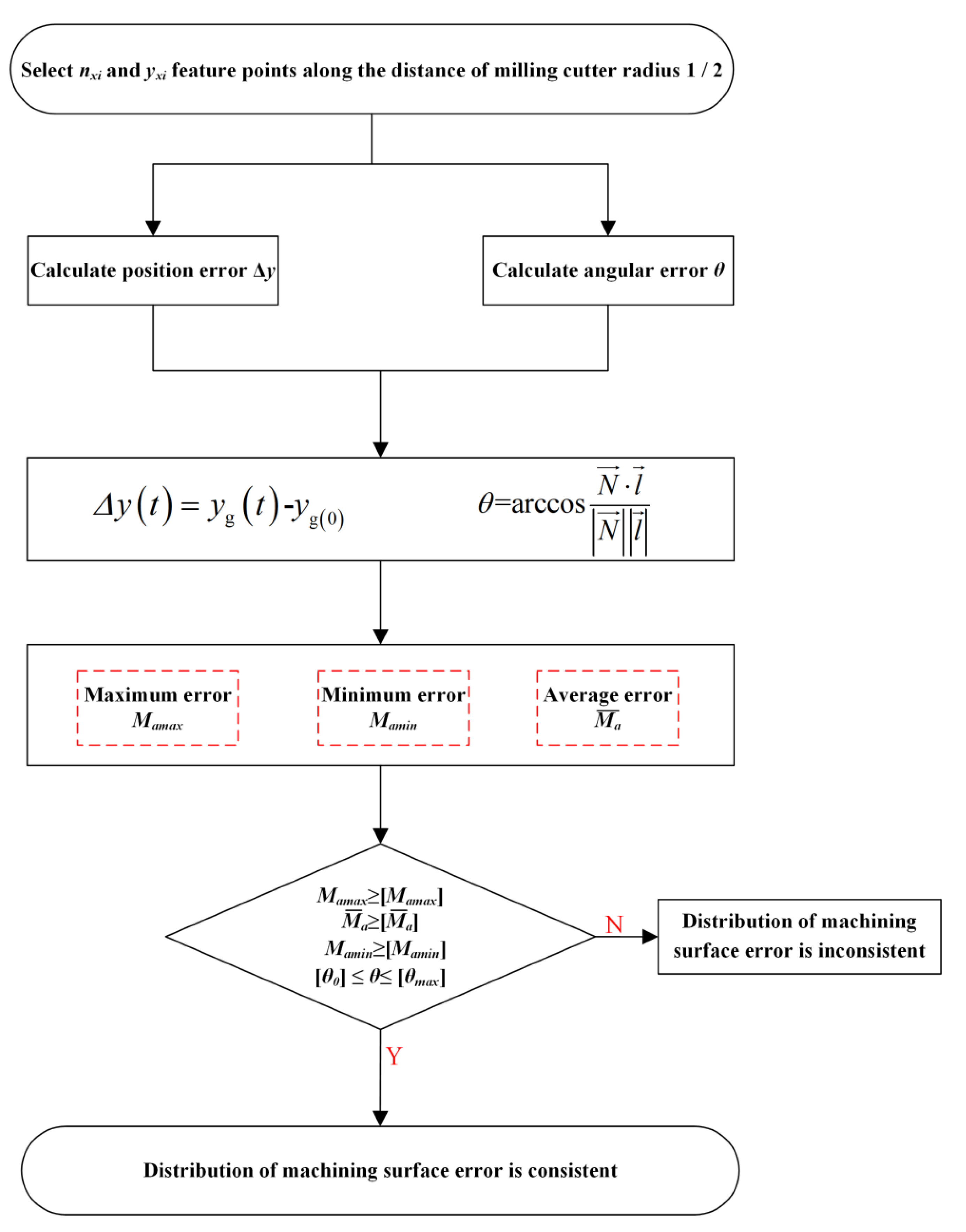
2.3. Consistency Evaluation Model of the Machined Surface Error Distribution
3. Influencing Factors and Interaction Identification of the Machined Surface Error
3.1. Screening of Influence Factors of the Machined Surface Error
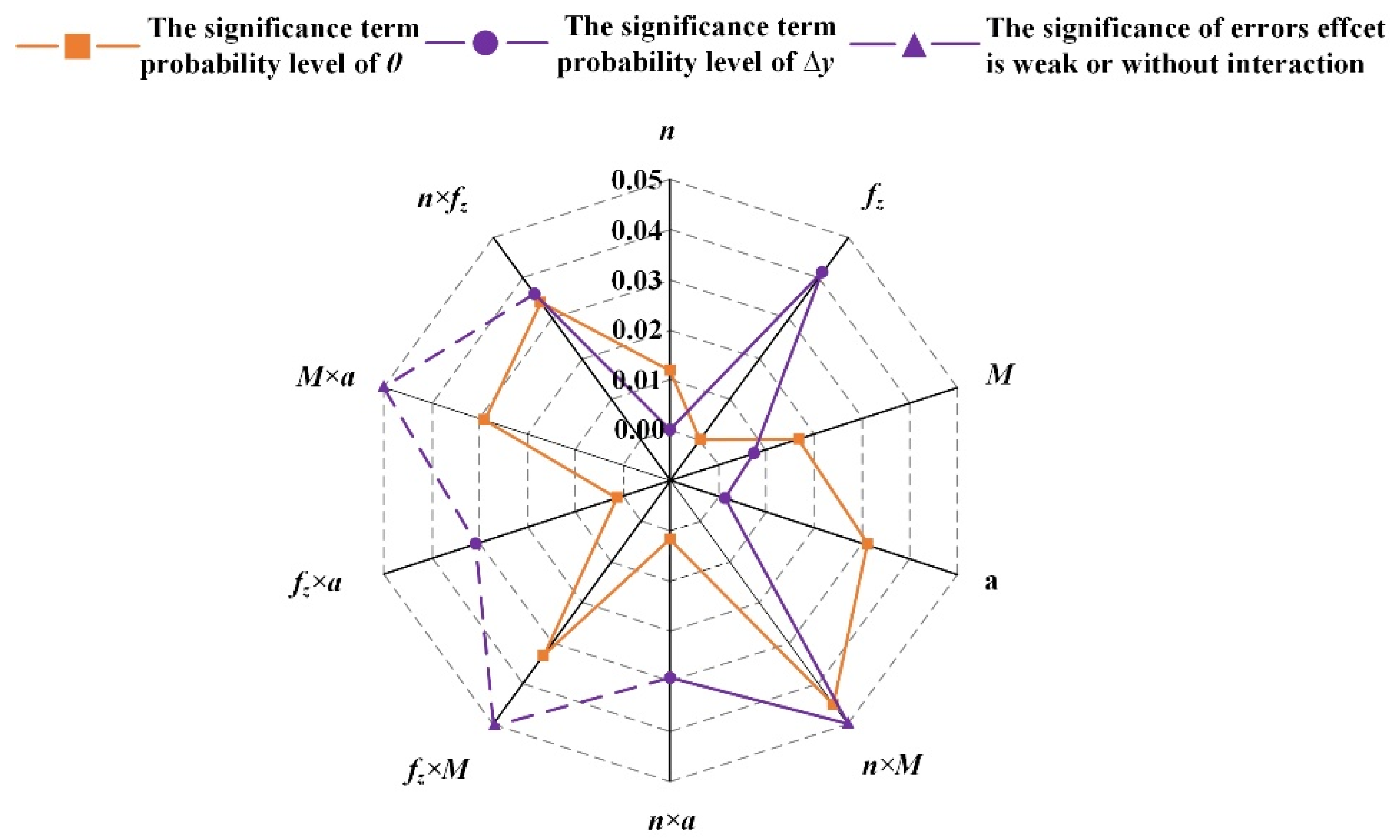
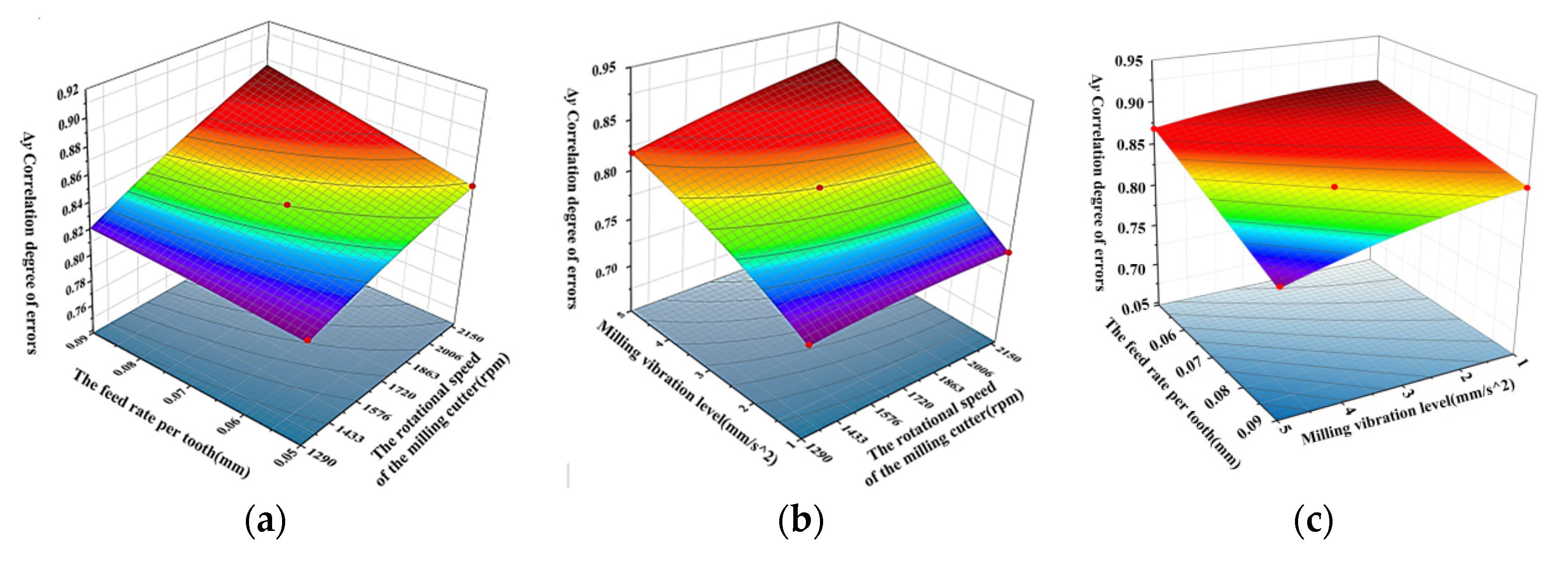
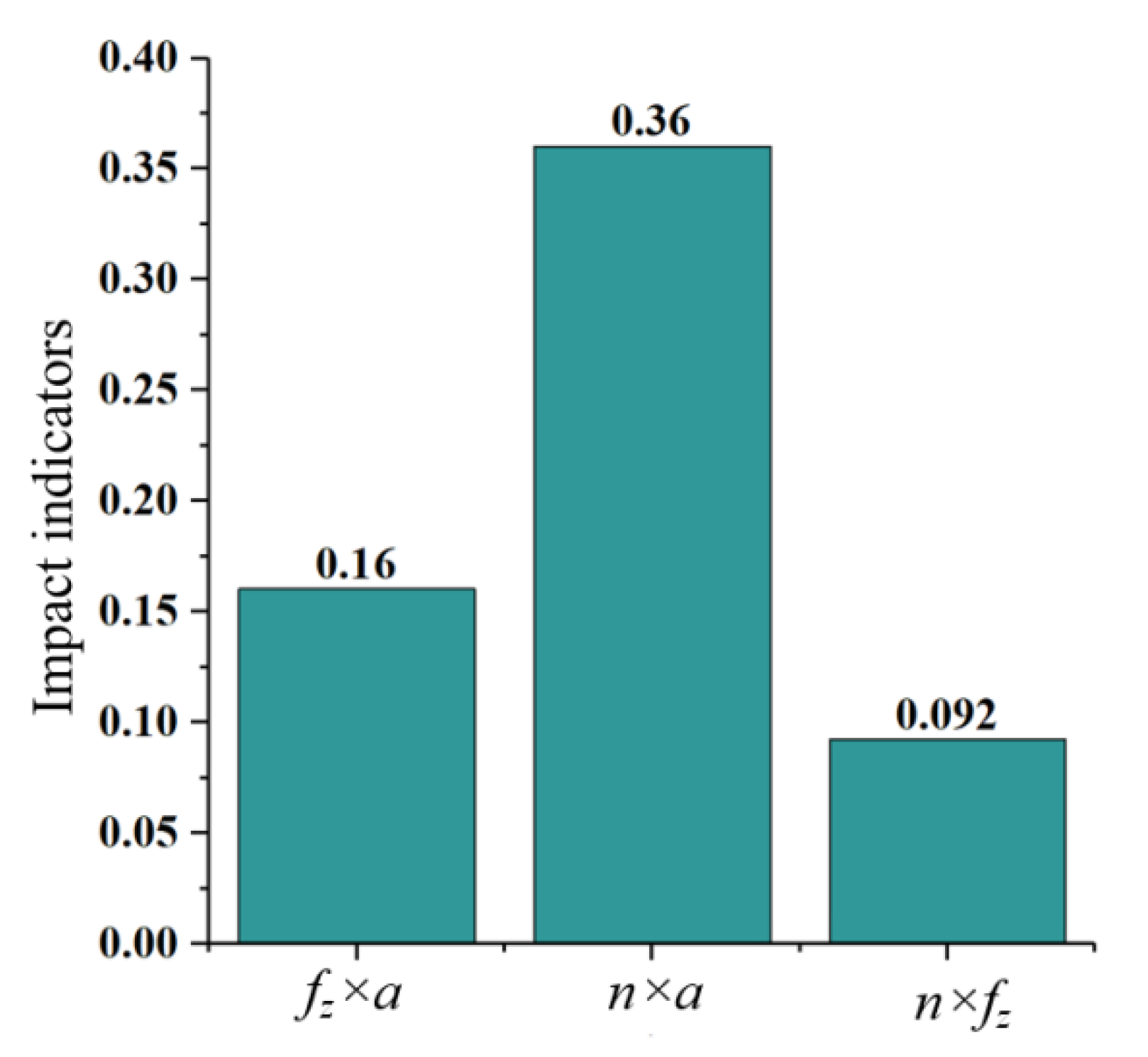
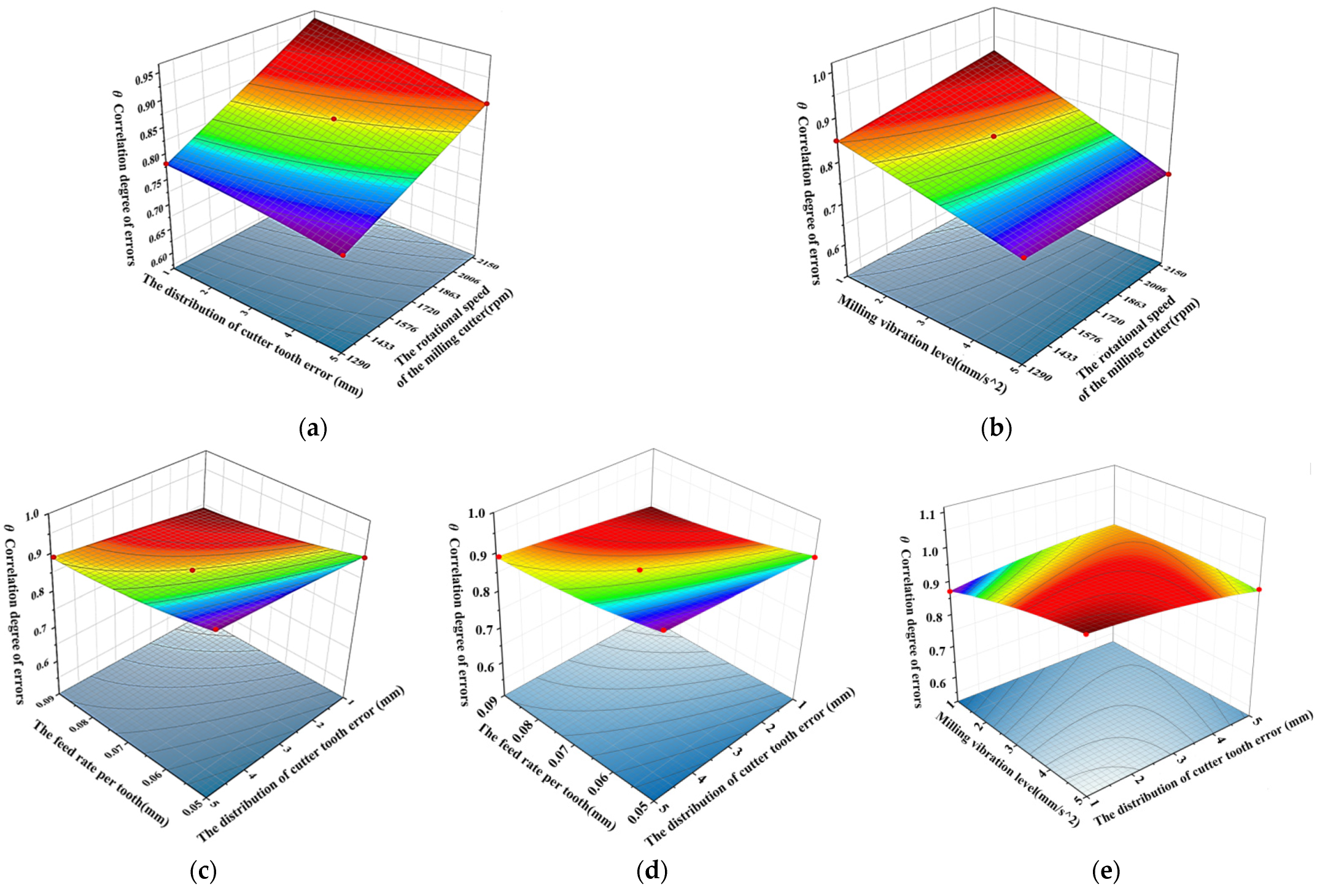
3.2. Interaction of Influencing Factors of the Machined Surface Error
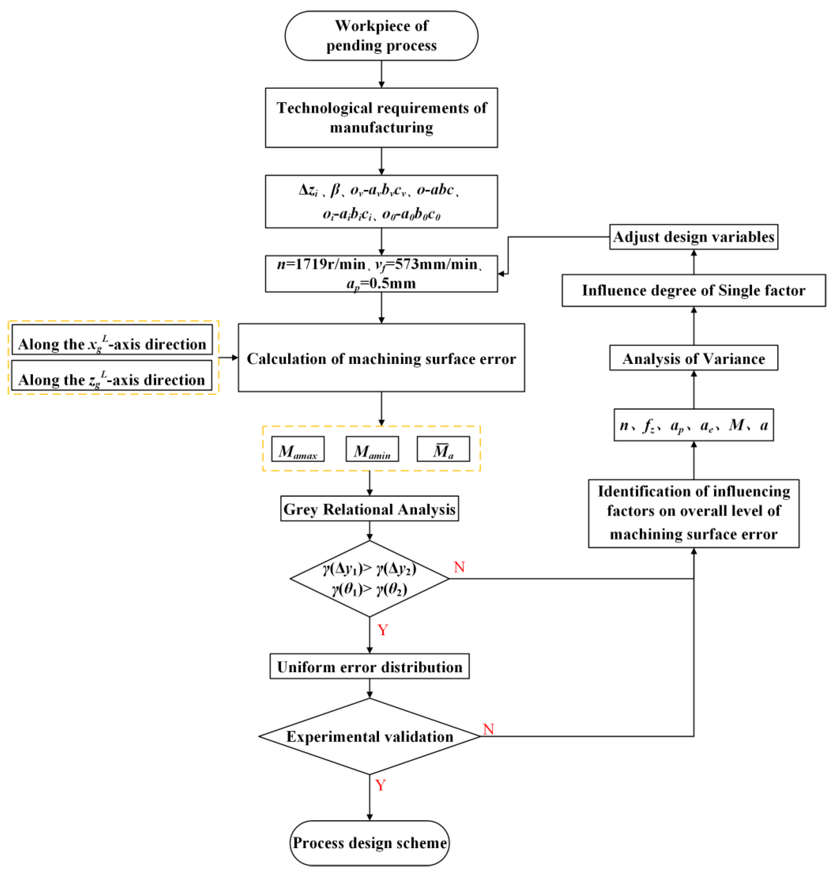
4. The Machined Surface Error Distribution Consistency Process Design Model
4.1. Process Planning Model
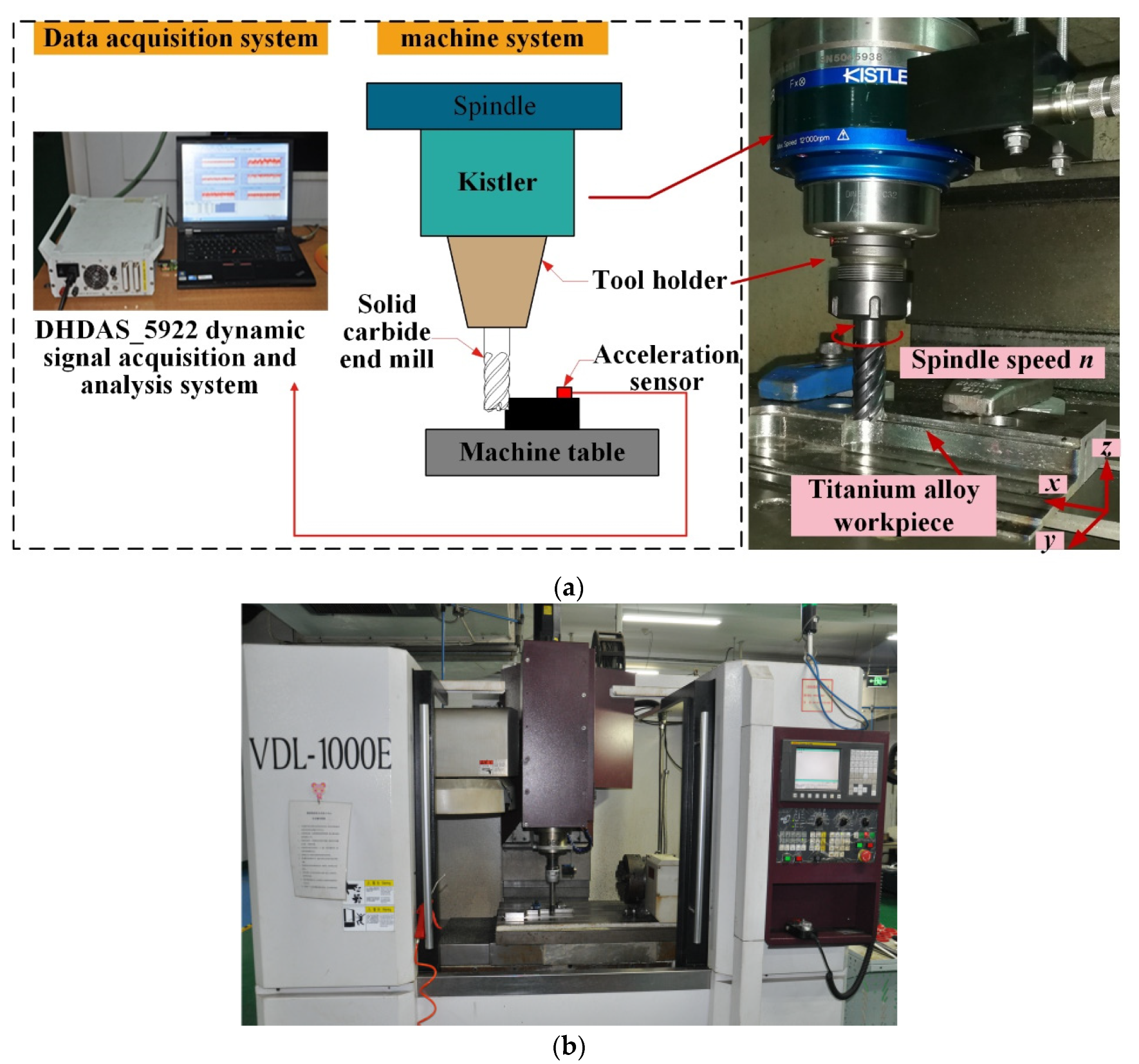
4.2. Experimental Verification
5. Conclusions
- (1)
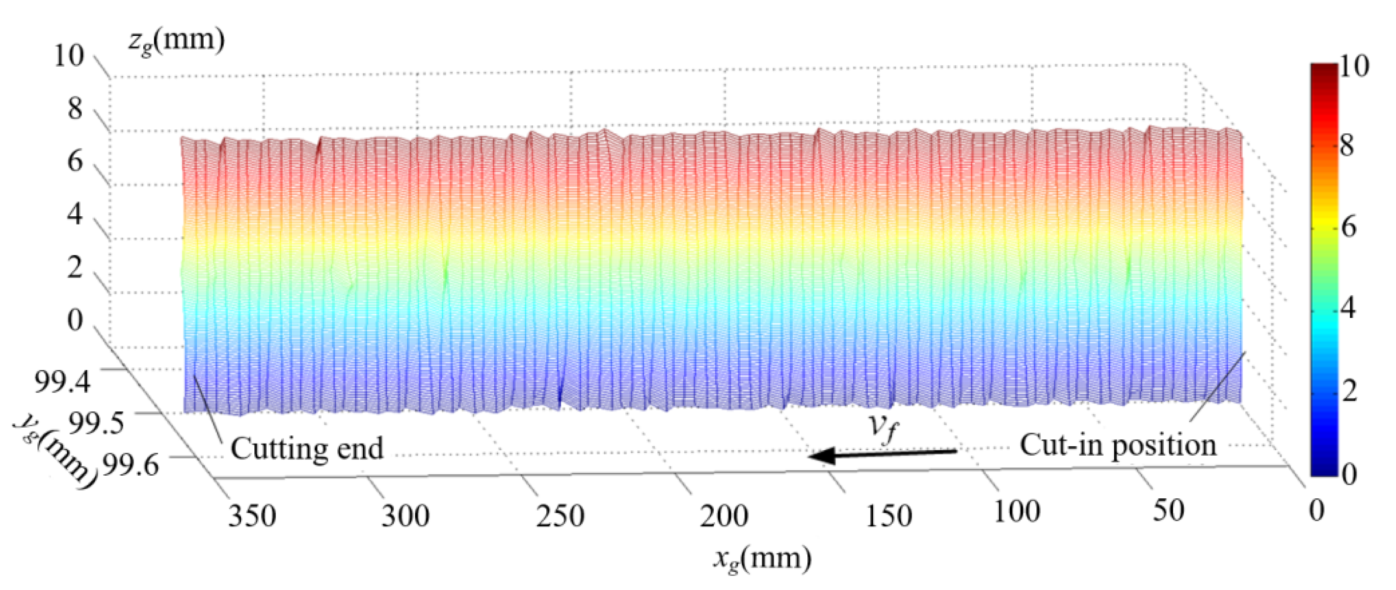
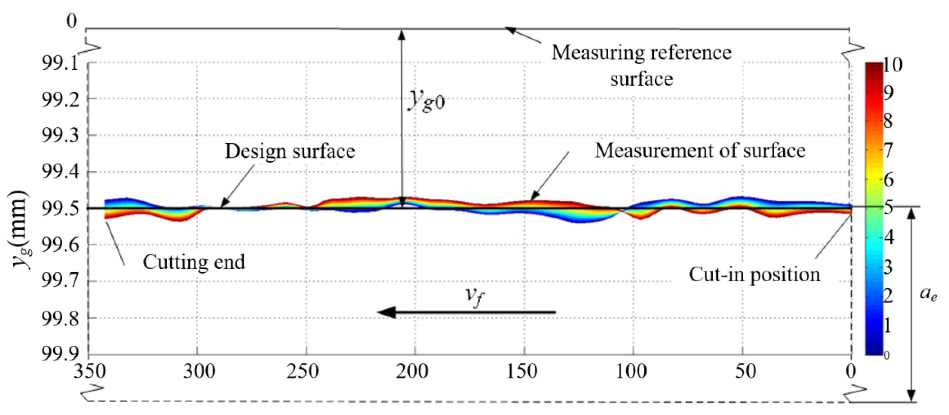
- An instantaneous cutting model of a high-efficiency milling cutter was developed. Considering the influence of vibration on the overall offset angle and distance of the milling cutter, a simulation model of the machined surface morphology was proposed, a model of the machined surface positional and angular error was developed, and a consistency evaluation model of milling error distribution was proposed.
- (2)
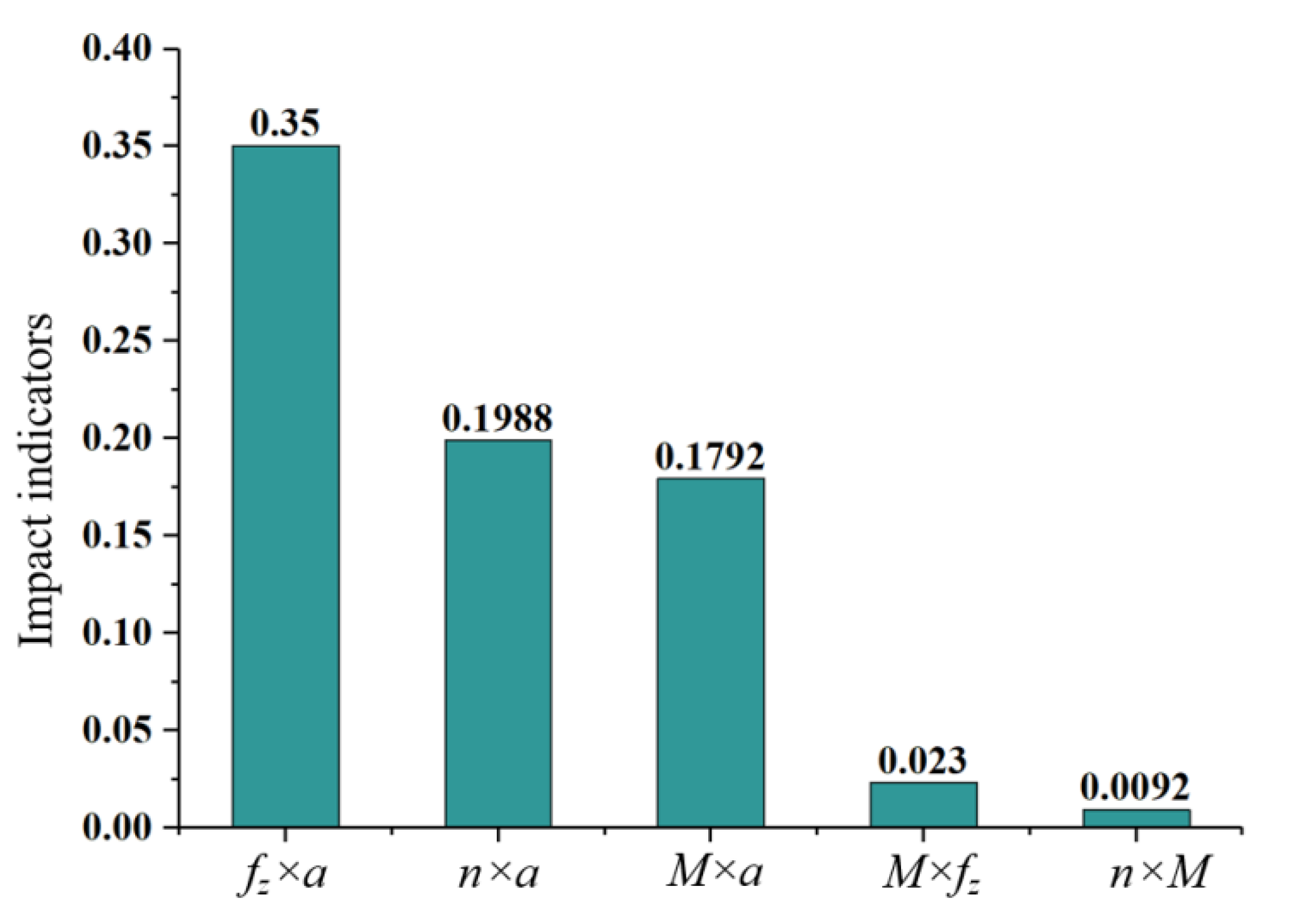
- The analysis results of the obvious aboriginality of the factors affecting the consistency of the milling error distribution show that the axial and radial errors of the cutter teeth have the most obvious influences on error distribution. At the same time, the positional and angular errors of the machined surface are sensitive to the spindle speed and the feed per tooth, respectively. The interaction of influencing factors of machined surface error distribution was analyzed by response surface methodology. The maximum indicator of the interaction between spindle speed and milling vibration on the milling surface positional error was 0.36, and the maximum indicator of the interaction between feed per tooth and milling vibration on the milling surface angular error was 0.35. These results show that the interactions caused by process parameters and milling vibration have obvious influences on the distribution consistency of machined surface error, while the interaction of cutter tooth radial and axial errors with process parameters is relatively insensitive.
- (3)
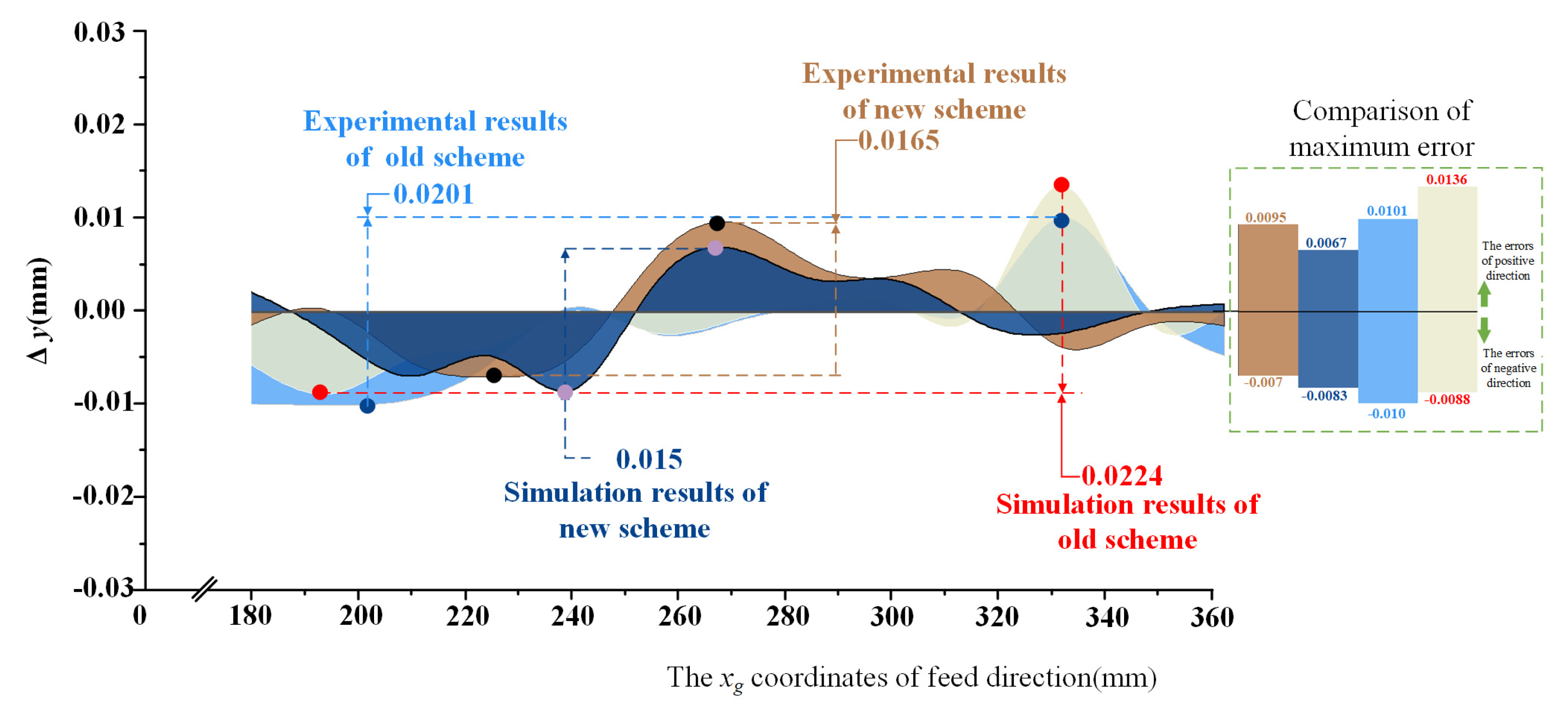
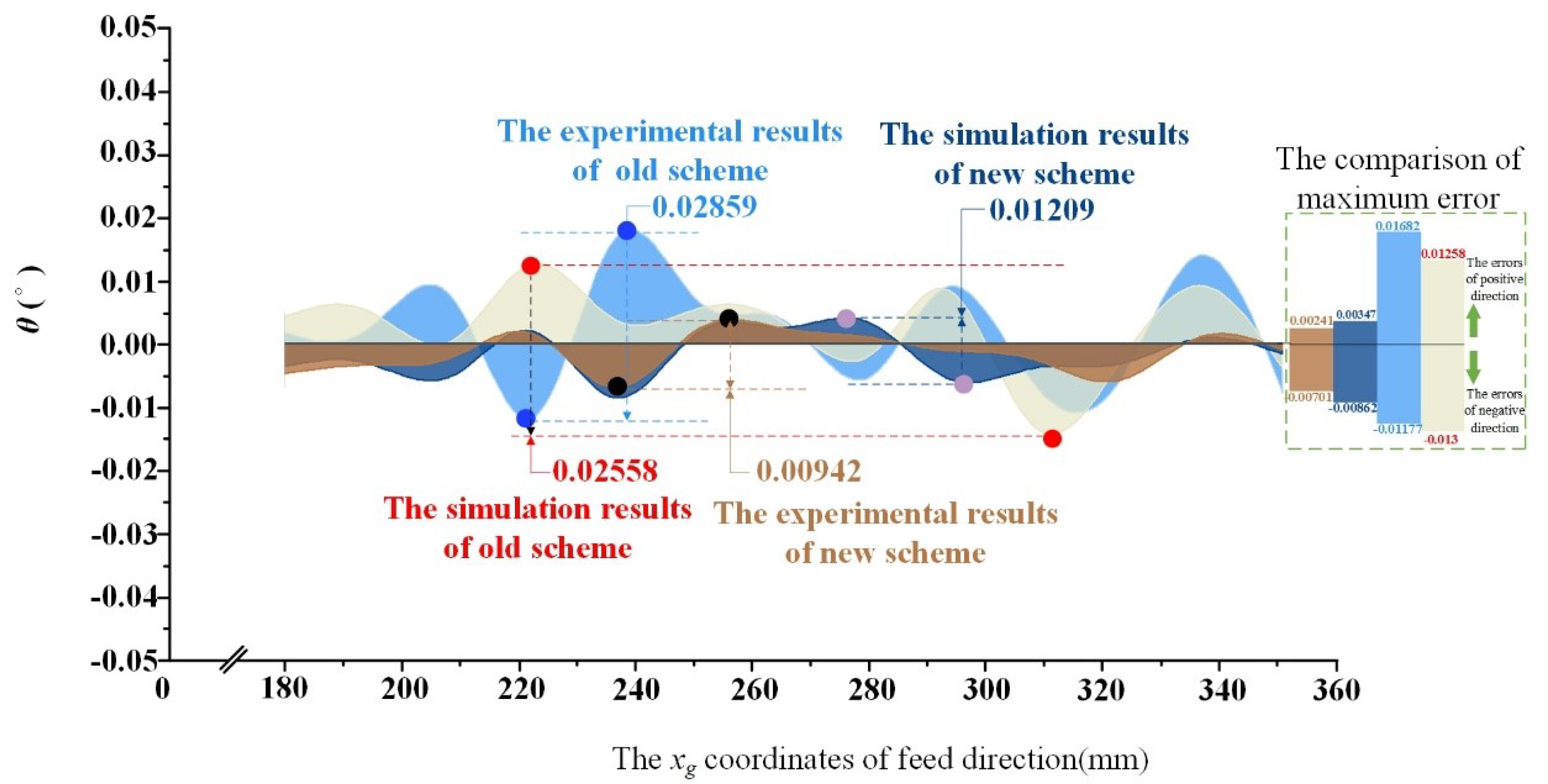
- Based on the analysis results of the influence of design variables, a process design model of machined surface error distribution consistency is proposed. The validation results show that the range of positional error of the new process scheme is 17.9% lower than that of the old process scheme, and the range of angular error is reduced by 52.7%, indicating that the error distribution of the new process scheme is relatively concentrated. In addition, through the comparative analysis of the new and old process schemes, the positional error and angular error of the new process scheme are obviously improved compared with those of the old process scheme, proving the efficiency of the proposed design model.
Author Contributions
Funding
Institutional Review Board Statement
Informed Consent Statement
Conflicts of Interest
References
- Wang, S.M.; Lee, C.Y.; Gunawan, H.; Yeh, C.C. An accuracy-efficiency-power consumption hybrid optimization method for CNC milling process. Appl. Sci. 2019, 9, 1495. [Google Scholar] [CrossRef] [Green Version]
- Li, L.; Deng, X.; Zhao, J.; Zhao, F.; Sutherland, J.W. Multi-objective optimization of tool path considering efficiency, energy-saving and carbon-emission for free-form surface milling. J. Clean. Prod. 2018, 172, 3311–3322. [Google Scholar] [CrossRef]
- Zhang, X.; Zhang, W.; Zhang, J.; Pang, B.; Zhao, W. Systematic study of the prediction methods for machined surface topography and form error during milling process with flat-end cutter. Proc. Inst. Mech. Eng. Part B J. Eng. Manuf. 2019, 233, 226–242. [Google Scholar] [CrossRef]
- Huang, T.; Zhang, X.M.; Ding, H. Error analysis of time-domain methods for milling stability prediction. Procedia CIRP 2018, 77, 457–460. [Google Scholar] [CrossRef]
- Eser, A.; Aşkar Ayyıldız, E.; Ayyıldız, M.; Kara, F. Artificial intelligence-based surface roughness estimation modelling for milling of AA6061 alloy. Adv. Mater. Sci. Eng. 2021, 2021, 5576600. [Google Scholar] [CrossRef]
- Zhuo, Y.; Han, Z.; An, D.; Jin, H. Surface topography prediction in peripheral milling of thin-walled parts considering cutting vibration and material removal effect. Int. J. Mech. Sci. 2021, 211, 106797. [Google Scholar] [CrossRef]
- Chan, T.C.; Hong, Y.P.; Yu, J.H. Effect of Moving Structure on the Spatial Accuracy and Compensation of the Coordinate Measuring Machine. Int. J. Precis. Eng. Manuf. 2021, 22, 1551–1561. [Google Scholar] [CrossRef]
- Xu, M.; Li, C.; Kurniawan, R.; Park, G.; Chen, J.; Ko, T.J. Study on surface integrity of titanium alloy machined by electrical discharge-assisted milling. J. Mater. Process. Technol. 2022, 299, 117334. [Google Scholar] [CrossRef]
- Wang, L.; He, Y.; Wang, Y.; Li, Y.; Liu, C.; Wang, S.; Wang, Y. Analytical modeling of material removal mechanism in dry whirling milling process considering geometry, kinematics and mechanics. Int. J. Mech. Sci. 2020, 172, 105419. [Google Scholar] [CrossRef]
- Usca, Ü.A.; Uzun, M.; Şap, S.; Kuntoğlu, M.; Giasin, K.; Pimenov, D.Y.; Wojciechowski, S. Tool wear, surface roughness, cutting temperature and chips morphology evaluation of Al/TiN coated carbide cutting tools in milling of Cu–B–CrC based ceramic matrix composites. J. Mater. Res. Technol. 2022, 16, 1243–1259. [Google Scholar] [CrossRef]
- Kaltenbrunner, T.; Krückl, H.P.; Schnalzger, G.; Klünsner, T.; Teppernegg, T.; Czettl, C.; Ecker, W. Differences in evolution of temperature, plastic deformation and wear in milling tools when up-milling and down-milling Ti6Al4V. J. Manuf. Process. 2022, 77, 75–86. [Google Scholar] [CrossRef]
- Zhang, M.; Zhang, D.; Geng, D.; Shao, Z.; Liu, Y.; Jiang, X. Effects of tool vibration on surface integrity in rotary ultrasonic elliptical end milling of Ti–6Al–4V. J. Alloy. Compd. 2020, 821, 153266. [Google Scholar] [CrossRef]
- Wang, C.; Ding, P.; Huang, X.; Gao, T.; Li, C.; Zhang, C. Reliability sensitivity analysis of ballend milling accuracy. Int. J. Adv. Manuf. Technol. 2021, 112, 2051–2064. [Google Scholar] [CrossRef]
- Deng, C.; Miao, J.; Ma, Y.; Wei, B.; Feng, Y. Reliability analysis of chatter stability for milling process system with uncertainties based on neural network and fourth moment method. Int. J. Prod. Res. 2020, 58, 2732–2750. [Google Scholar] [CrossRef]
- Xiong, Z.; Lianyu, Z.; Wei, F. Adaptive optimization of milling process parameters for thin-walled parts driven by real-time vibration data. Chin. J. Mech. Eng. 2020, 56, 172–184. [Google Scholar] [CrossRef]
- Aslan, A. Optimization and analysis of process parameters for flank wear, cutting forces and vibration in turning of AISI 5140: A comprehensive study. Measurement 2020, 163, 107959. [Google Scholar] [CrossRef]
- Salur, E.; Aslan, A.; Kuntoglu, M.; Gunes, A.; Sahin, O.S. Experimental study and analysis of machinability characteristics of metal matrix composites during drilling. Compos. Part B Eng. 2019, 166, 401–413. [Google Scholar]
- Pimenov, D.Y.; Bustillo, A.; Wojciechowski, S.; Sharma, V.S.; Gupta, M.K.; Kuntoğlu, M. Artificial intelligence systems for tool condition monitoring in machining: Analysis and critical review. J. Intell. Manuf. 2022, 33, 1–43. [Google Scholar] [CrossRef]
- Kuntoğlu, M.; Salur, E.; Gupta, M.K.; Sarıkaya, M.; Pimenov, D.Y. A state-of-the-art review on sensors and signal processing systems in mechanical machining processes. Int. J. Adv. Manuf. Technol. 2021, 116, 2711–2735. [Google Scholar] [CrossRef]
- Wei, W.; Li, Y.; Xu, Y.; Yang, C. Research on tool wear factors for milling wood-plastic composites based on response surface methodology. Bioresources 2021, 16, 151. [Google Scholar] [CrossRef]
- Daniel, S.A.A.; Pugazhenthi, R.; Kumar, R.; Vijayananth, S. Multi objective prediction and optimization of control parameters in the milling of aluminium hybrid metal matrix composites using ANN and Taguchi-grey relational analysis. Def. Technol. 2019, 15, 545–556. [Google Scholar] [CrossRef]

| Number | Parameters | Meaning of Parameters |
|---|---|---|
| 1 | og-xgygzg | Workpiece coordinate system, where og is the origin of the coordinates, which is the vertex behind the bottom of the cutting end of the milling workpiece. The xg axis is the same as the feed speed direction of the milling cutter, the yg axis is parallel to the milling width direction, and the zg axis is parallel to the cutting depth direction. |
| 2 | o-abc | Cutting coordinate system without milling vibration, where o is the origin of the coordinates, located at the center of the milling cutter bottom. The a axis is parallel to the feed speed direction, the b axis is parallel to the cutting width direction, and the c axis is parallel to the cutting depth direction. |
| 3 | ov-avbvcv | Cutting coordinate system with milling vibration, where ov is the coordinate origin, which is the position of the center point o of the bottom surface of the milling cutter under the vibration of the milling cutter. The av axis is the milling cutter ideal coordinate system’s a axis vibration offset state, the bv axis is the milling cutter ideal coordinate system’s b axis vibration offset state, and the cv axis is the milling cutter ideal coordinate system’s c0 axis vibration offset state. |
| 4 | oi-aibici | Cutter tooth coordinate system, where oi is the knife point. The ai axis is perpendicular to the cutter tooth’s instantaneous cutting speed direction, and points to the cutter center. The bi axis is parallel to the instantaneous cutting speed direction of the cutter tooth, and the ci axis is parallel to the milling cutter spindle. |
| 5 | o0-a0b0c0 | Structure coordinate system of the milling cutter, Where o0 is the coordinate origin and is the intersection point of the milling cutter axis and the surface where the minimum point of the cutter tooth is located, where the a0 axis is in the plane where the minimum point of the cutter tip is located, and is perpendicular to the b0 axis, while the b0 axis is in the plane where the minimum point of the cutter tooth is located, and points to the tipping point with the largest outer diameter. |
| 6 | ΔZi | Milling cutter tooth axial error. |
| 7 | xg(L) | The value of workpiece length on the xg axis in the workpiece coordinate system. |
| 8 | yg(W) | The value of workpiece width on the yg axis in the workpiece coordinate system. |
| 9 | zg(H) | The value of workpiece height the on zg axis in the workpiece coordinate system. |
| 10 | mi(c1) | Any point on the cutting edge of the milling cutter that participates in the cutting part is the ith tooth, and the c axis coordinate of the milling cutter coordinate system is c1. |
| 11 | mj(c2) | Any point on the cutting edge of the milling cutter that does not coincide with mi(c1) in the cutting part is the jth tooth, and the coordinate of axis c of the milling cutter coordinate system is c2. |
| 12 | ∑1 | The plane is parallel to the aob plane of the milling cutter coordinate system at point mi(c1). |
| 13 | ∑2 | Parallel plane of point mj(c2) and the milling cutter coordinate system’s aob plane. |
| 14 | Vf | The milling cutter’s feed rate. |
| 15 | δ | The space angle between the milling cutter spindle and the ideal-state milling cutter spindle under vibration. |
| 16 | φsi | The angle between the cutter tooth coordinate system of cutter tooth i and the cutter structure coordinate system. |
| 17 | φq(t) | The angle between the cutter tooth structure coordinate system and the cutting coordinate system under vibration. |
| 18 | β | The helix angle of the milling cutter. |
| Design Variable | Level 1 | Level 2 | Level 3 | Level 4 | Level 5 |
|---|---|---|---|---|---|
| n (rpm) | 1290 | 1462 | 1634 | 1806 | 1978 |
| fz (mm/z) | 0.05 | 0.06 | 0.07 | 0.08 | 0.09 |
| ap (mm) | 10 | 12 | 14 | 16 | 18 |
| ae (mm) | 0.5 | 0.6 | 0.7 | 0.8 | 0.9 |
| Vibration acceleration of zgL-axis direction (m/s2) | 1.79 | 1.22 | 1.86 | 3.23 | 2.54 |
| Vibration acceleration of xgL-axis direction (m/s2) | 0.96 | 1.04 | 1.15 | 1.53 | 1.69 |
| Vibration acceleration of ygL-axis direction (m/s2) | 2.19 | 5.40 | 2.21 | 5.92 | 5.74 |
| Milling Cutter Number | Cutter Tooth Error (mm) | |||||
|---|---|---|---|---|---|---|
| Milling cutter 1 | Δzi | 0.046 | 0.007 | 0.017 | 0.036 | 0.028 |
| Δri | 0.026 | 0.056 | 0.016 | 0.028 | 0.019 | |
| Milling cutter 2 | Δzi | 0.044 | 0.032 | 0.008 | 0.025 | 0.027 |
| Δri | 0.005 | 0.012 | 0.009 | 0.028 | 0.036 | |
| Milling cutter 3 | Δzi | 0.023 | −0.012 | −0.023 | 0.031 | −0.024 |
| Δri | 0.015 | −0.003 | 0.013 | −0.007 | 0.002 | |
| Milling cutter 4 | Δzi | 0.012 | 0.022 | 0.034 | −0.017 | 0.026 |
| Δri | −0.013 | 0.002 | 0.021 | 0.022 | 0.015 | |
| Milling cutter 5 | Δzi | 0.013 | 0.008 | −0.023 | 0.027 | 0.038 |
| Δri | 0.001 | 0.012 | −0.011 | −0.028 | 0.003 | |
| Design Variable | Variance | ||||
|---|---|---|---|---|---|
| Δy | θ | ||||
| n | 0.00012 | 0.00038 | |||
| fz | 0.00021 | 0.00014 | |||
| Cutter tooth error | 0.00023 | 0.00078 | |||
| Milling vibration | 0.00012 | 0.00035 | |||
| F | p-Value | F crit | |||
| Δy | θ | Δy | θ | Δy | θ |
| 3.8191 | 4.4814 | 0.0308 | 0.0182 | 3.2388 | 3.2388 |
| Serial Number | n (rpm) | fz (mm) | M | a | Serial Number | n (rpm) | fz (mm) | M | a |
|---|---|---|---|---|---|---|---|---|---|
| 1 | 1720 | 0.07 | M3 | a5 | 12 | 1720 | 0.07 | M3 | a4 |
| 2 | 1290 | 0.05 | M1 | a5 | 13 | 1290 | 0.09 | M4 | a5 |
| 3 | 1720 | 0.07 | M3 | a3 | 14 | 1720 | 0.07 | M3 | a3 |
| 4 | 2443 | 0.07 | M3 | a3 | 15 | 1720 | 0.07 | M2 | a3 |
| 5 | 1720 | 0.07 | M2 | a3 | 16 | 2150 | 0.05 | M5 | a1 |
| 6 | 2150 | 0.09 | M4 | a1 | 17 | 1720 | 0.07 | M3 | a2 |
| 7 | 1290 | 0.09 | M5 | a4 | 18 | 1720 | 0.04 | M3 | a3 |
| 8 | 1720 | 0.10 | M3 | a3 | 19 | 1720 | 0.07 | M3 | a3 |
| 9 | 1720 | 0.07 | M3 | a3 | 20 | 996 | 0.07 | M3 | a3 |
| 10 | 2150 | 0.09 | M1 | a5 | 21 | 1290 | 0.05 | M1 | a1 |
| 11 | 2150 | 0.05 | M5 | a5 |
| Element | Ti | Al | V | Fe | O | Si | C | N | H | Others |
|---|---|---|---|---|---|---|---|---|---|---|
| Contents (%) | Balance | 5.5~6.8 | 3.5~4.5 | 0.3 | 0.2 | 0.15 | 0.1 | 0.05 | 0.01 | 0.5 |
| Serial Number | n (r/min) | fz (mm/z) | ap (mm) | ae (mm) | Cutter Tooth Error (mm) | i = 1 | i = 2 | i = 3 | i = 4 | i = 5 |
|---|---|---|---|---|---|---|---|---|---|---|
| Original process scheme | 1719 | 0.06 | 10 | 0.5 | Δzi | −0.004 | −0.001 | −0.013 | 0 | −0.009 |
| Δri | 0.000 | −0.029 | −0.039 | −0.010 | −0.018 | |||||
| New Process Scheme | 1290 | 0.09 | 10 | 0.5 | Δzi | 0.005 | −0.019 | −0.014 | 0.000 | −0.009 |
| Δri | −0.001 | −0.006 | −0.006 | −0.004 | −0.000 |
| Cutting Depth of the Milling Cutter | Δy | θ | ||||||
|---|---|---|---|---|---|---|---|---|
| Mamax | Mamin | γ | Mamax | Mamin | γ | |||
| ap = 0 mm | 0.0138 | −0.0172 | −0.00124 | 0.95 | 0.017562 | −0.01961 | −0.00127 | 0.73 |
| ap = 5 mm | 0.0101 | −0.0100 | −0.00108 | 0.92 | 0.01554 | −0.01699 | −0.00256 | 0.82 |
| ap = 10 mm | 0.0156 | −0.0161 | −0.00144 | 0.88 | 0.020612 | −0.0179 | 2.44 × 10⁻⁵ | 0.77 |
| Cutting Depth of the Milling Cutter | Δy | θ | ||||||
|---|---|---|---|---|---|---|---|---|
| Mamax | Mamin | γ | Mamax | Mamin | γ | |||
| ap = 0 mm | 0.0151 | −0.0081 | 0.003956 | 0.91 | 0.0273 | −0.0238 | 0.001672 | 0.87 |
| ap = 5 mm | 0.0095 | −0.007 | 0.00056 | 0.90 | 0.0168 | −0.0156 | 0.000759 | 0.83 |
| ap = 10 mm | 0.0118 | −0.108 | 0.002193 | 0.85 | 0.0189 | −0.0318 | −0.0012 | 0.82 |
Publisher’s Note: MDPI stays neutral with regard to jurisdictional claims in published maps and institutional affiliations. |
© 2022 by the authors. Licensee MDPI, Basel, Switzerland. This article is an open access article distributed under the terms and conditions of the Creative Commons Attribution (CC BY) license (https://creativecommons.org/licenses/by/4.0/).
Share and Cite
Zhao, P.; Jiang, Y.; Jiang, B.; Ma, C. An Innovative Process Design Model for Machined Surface Error Distribution Consistency in High-Efficiency Milling. Appl. Sci. 2022, 12, 7199. https://doi.org/10.3390/app12147199
Zhao P, Jiang Y, Jiang B, Ma C. An Innovative Process Design Model for Machined Surface Error Distribution Consistency in High-Efficiency Milling. Applied Sciences. 2022; 12(14):7199. https://doi.org/10.3390/app12147199
Chicago/Turabian StyleZhao, Peiyi, Yupeng Jiang, Bin Jiang, and Chaoyang Ma. 2022. "An Innovative Process Design Model for Machined Surface Error Distribution Consistency in High-Efficiency Milling" Applied Sciences 12, no. 14: 7199. https://doi.org/10.3390/app12147199
APA StyleZhao, P., Jiang, Y., Jiang, B., & Ma, C. (2022). An Innovative Process Design Model for Machined Surface Error Distribution Consistency in High-Efficiency Milling. Applied Sciences, 12(14), 7199. https://doi.org/10.3390/app12147199