Review

A State of the Art Review on Sensible and Latent Heat Thermal Energy Storage Processes in Porous Media: Mesoscopic Simulation

1
Thermal and Energetic Systems Studies Laboratory (LESTE), National School of Engineers of Monastir, Monastir University, Rue Ibn Jazza, Monastir 5019, Tunisia
2
Univ. Artois, IMT Nord Europe, Junia, Univ. Lille, ULR 4515, Laboratoire de Génie Civil et géo-Environnement (LGCgE), F-62400 Béthune, France
3
Center of Flow Simulation (CFS), Department of Mechanical and Process Engineering, Duesseldorf University of Applied Sciences, Münsterstraße 156, D-40476 Duesseldorf, Germany
*
Author to whom correspondence should be addressed.
Appl. Sci. 2022, 12(14), 6995; https://doi.org/10.3390/app12146995
Submission received: 13 March 2022 / Revised: 20 April 2022 / Accepted: 13 June 2022 / Published: 11 July 2022
(This article belongs to the Special Issue Latent Heat Storage)

Abstract

:
Sharing renewable energies, reducing energy consumption and optimizing energy management in an attempt to limit environmental problems (air pollution, global warming, acid rain, etc.) has today become a genuine concern of scientific engineering research. Furthermore, with the drastic growth of requirements in building and industrial worldwide sectors, the need for proper techniques that allow enhancement in the thermal performance of systems is increasingly being addressed. It is worth noting that using sensible and latent heat storage materials (SHSMs and phase change materials (PCMs)) for thermal energy storage mechanisms can meet requirements such as thermal comfort in buildings when selected correctly. However, as the operating temperature changes, a series of complex technical issues arise, such as heat transfer issues, leaks, corrosion, subcooling, supercooling, etc. This paper reviews the most recent research advances in the area of sensible and latent heat storage through the porous media as potential technology while providing useful information for researchers and engineers in the energy storage domain. To this end, the state and challenges of PCMs incorporation methods are drawn up, and an updated database of various research is provided while discussing the conclusions concerning the sensible and latent heat storage in porous media, their scopes of application and impact on energy consumption. In the light of this non-exhaustive review, it turns out that the adoption of porous matrices improves the thermal performance of systems, mitigates energy consumption and drops CO2 emissions while ensuring thermal comfort within buildings. In addition, at the representative elementary volume (REV) and pore scales, the lattice Boltzmann method (LBM) is examined as an alternative method to the commonly used, traditional numerical methods. These two approaches are compared based on results available in the literature. Through these means, their ability to handle latent and sensible heat storage process in a porous medium is demonstrated. To sum up, to be more complete, perspectives of sensible and latent energy storage technologies are covered.

1. Introduction

Nowadays, the energy storage sector figures as a fundamental technology facing the rapid development of industrialization and urbanization. Thereby, over the years, energy storage systems (ESSs) technology has been widely developed to ensure the renewable energy resources sustainability and to balance the gap between energy demand and supply [1]. Throughout history, along with the increase in human population, the global consumption of energy continues to increase, as shown clearly observed in Figure 1. Energy consumption is observed to increase faster than population size [2]. Yet, it is noteworthy to highlight the industrialization and welfare level as the main factors responsible for the tremendous increase in energy consumption.
Inevitably, it is crucial to implement ESS into energy systems not only to limit the intermittency of renewable energies but also to facilitate the flexibility of energy systems while increasing their efficiency. Generally, the use of ESSs is aimed at matching the energy demand and supply. As illustrated in Table 1, there are different ESSs approaches that can be used in various engineering applications [3].
Among several ES methods, TES appears as one of the emerging technologies that can bridge the intermittency gap in renewables such as solar energy [4], energy saving and the promotion of environmental respect (greener world). TES systems consist of a thermal energy storage medium (heat and/or cold) kept for a defined period to use it when and where it is needed [4,5]. The applications of these systems (TES) are in the building sector (air conditioning, thermal comfort, domestic hot water, etc.) and industrial sector(chemical industry, food industry, etc.) [6]. It is worthy to emphasize that the estimated annual energy savings potential in the European Union (EU) is 7.5% thanks to the implementation of these technologies [7].In terms of environmental savings, the annual potential CO2 emissions were reduced by about 5.5% in the EU [7]. Later, 90% of the CO2 emissions mitigation is expected by 2050 (according to the international renewable energy agency (IRENA)) through the application of these systems (Figure 2) [8]. Since then, these systems have received particular attention through an economic and environmental analysis in several sectors (Figure 2).
According to Calderón et al. [9], more than 14,000 publications have been achieved over the last decade, showing that scientific research is increasingly productive in the TES field. However, the choice of an appropriate TES system depends on various factors, basically depending on the targeted field of application, technical conditions (volume, temperature span, etc.), storage time and economic aspect (marketing and cost-effectiveness) [10]. Considering the characteristics of the storage period, there are two concepts of TES systems called short-term storage systems and long-term storage systems. The first concept is a storage cycle of a few hours known as diurnal heat storage [11], while the second is known as storage seasonal heat [12]. In this context and by way of example, the seasonal TES (STES) stores the heat collected in the summer for up to more than three months (charging period) using thermal solar power plants to be used in winter (discharging period) [13]. It is worth noting that this reverse process can obviously be applied. Therefore, this second category of TES systems (STES) has a significant contribution to the efficient use of renewable in building applications such as decarbonization and district heating [14,15]. Note that such a category competes with others on a large scale such as natural gas storage, pumped storage hydroelectric system and heat generation methods. Yet, sector coupling remains as the most important challenge for future energy concepts. Furthermore, large-scale TES systems are needed for the conception of any other technology to ensure system stability and resilience. In addition, depending on the energy storage method deemed, TES solutions can be classified into three categories, viz., sensible heat storage (SHS), latent heat storage (LHS) using PCMs and thermochemical heat storage (TCHS). Moreover, these classes can be implemented in active or passive buildings [16,17]. In passive building technology, only the SHS and LHS methods are used, which allow improving thermal comfort through materials use with high thermal inertia [16,18]. As for the concept of active buildings, the TCHS method, which enables to attenuate the peak load, is the one that is rather used as it increases renewable energies contributions such as solar and aerothermal energies [17,18]. It improves the efficiency of systems by regulating the process range, for example using frequent starts/stops to reduce discontinuous inputs [17,18]. In this context, Ben Romdhane et al. [19] documented a review of passive building applications based on the LHS method while comparing it to the SHS approach. They reported that the LHS technique stores five to 14 times more heat than the SHS method. Otherwise, Rathore and Shukla [20] presented a review of the different types of TES used in construction while paying great attention to LHS materials. Furthermore, a description dealing with several LHS designs has been provided, which has indicated that a macro-encapsulated phase change material (MPCM) could be used for a period of time, helping to alleviate the reliance on heating and cooling devices and, thereby, saving energy.
Lizana et al. [18] reviewed the development and applications of thermal energy storage materials for zero energy buildings (ZEBs). Different properties, designs, and classifications of sensible, latent and thermochemical TES materials have been described and compared based on recent scientific research, well-known international projects, and commercial systems. They revealed that there exists a shortage of materials for TCHS solutions while noting that the thermochemical method requires well-maintained tanks and heat exchangers for small-scale processes. Thereby, further efforts are still needed to optimize the technical and economic concept of TCHS systems. In parallel, Navarro et al. [17] conducted a comprehensive review of TES technologies embedded into active buildings. It is worth noting that there are two types of active systems, viz direct and indirect systems where the storage medium is either the heat transfer fluid (HTF) or another medium. These authors stated that the active systems design requires proper maintenance to achieve suitable incorporation, taking into account various conditions and requirements that may be climatic, aesthetic and/or operational. Each type of TES has its advantages and disadvantages, the operating principle of which depends on the targeted application, such as capacity or power.
A comparison of some TES methods is reported in Table 2 [21].
For some time now, various articles on energy storage have been published, pointing out research trends and drawing up the state of the art [9,22,23,24,25]. In this, Cabeza et al. [26] issued a bibliometric analysis using VOSviewer software to develop research related to TES categories and identify research gaps. For TES topics, the approach performed using the co-occurrence of the keywords found is illustrated in Figure 3. Through this diagram, it appears that terms relevance can be identified from the circles size. Simply stated, a larger circle identifies the subject with more studies. Furthermore, the research gaps are identified by smaller circles. As shown and indicated in Ref. [27], subjects TES (red circle) and LHS with PCMs (purple circle) indicate high relevance, meaning that they are the focus of intense investigation both experimentally and/or numerically. The benefit of this overview is to serve as a guide for any reader interested in the decision-making process in evolving TES solutions for different industries.
The main aim and scope of this article is to provide an in-depth review of the state of the art of TES technologies with particular attention to SHS and LHS systems and their applications in various sectors. It also addresses the subject of phase change heat transfer and the sensible energy storage processes in porous media. Furthermore, in recent years, the research has moved toward numerical methods to explore the potential of these technologies at a theoretical level. Thereby, numerical approaches such as mesoscopic REV- and pore-scale approaches will be taken up herein to point out their ability to deal with some mechanisms that may occur in these systems. It is worth mentioning here that this review article can serve as a guide for researchers seeking to identify trends in research on latent and sensible heat storage technologies using porous structures as a new strategy to evaluate performance of these systems. Among these trends, we can cite LBM approaches where an overview is given here with a comparison to other traditional numerical methods to draw the attention of readers to the emerging trends.
The remaining parts of this review are arranged as follows. First, in Section 2, a comprehensive analysis of sensible energy storage technique is provided while highlighting the different sensible heat storage materials and the porous medium effect. Then, in Section 3, the technical design, economic properties and many other characteristics of latent energy storage technologies are reviewed. In Section 4, a comparison between the SHS and LHS options is presented. The LBM at REV and pore scale methods, including new solutions of simulating heat transfer mechanisms in porous supports and recent developments, are covered in Section 5. Finally, in Section 6, conclusions of the present review are drawn.

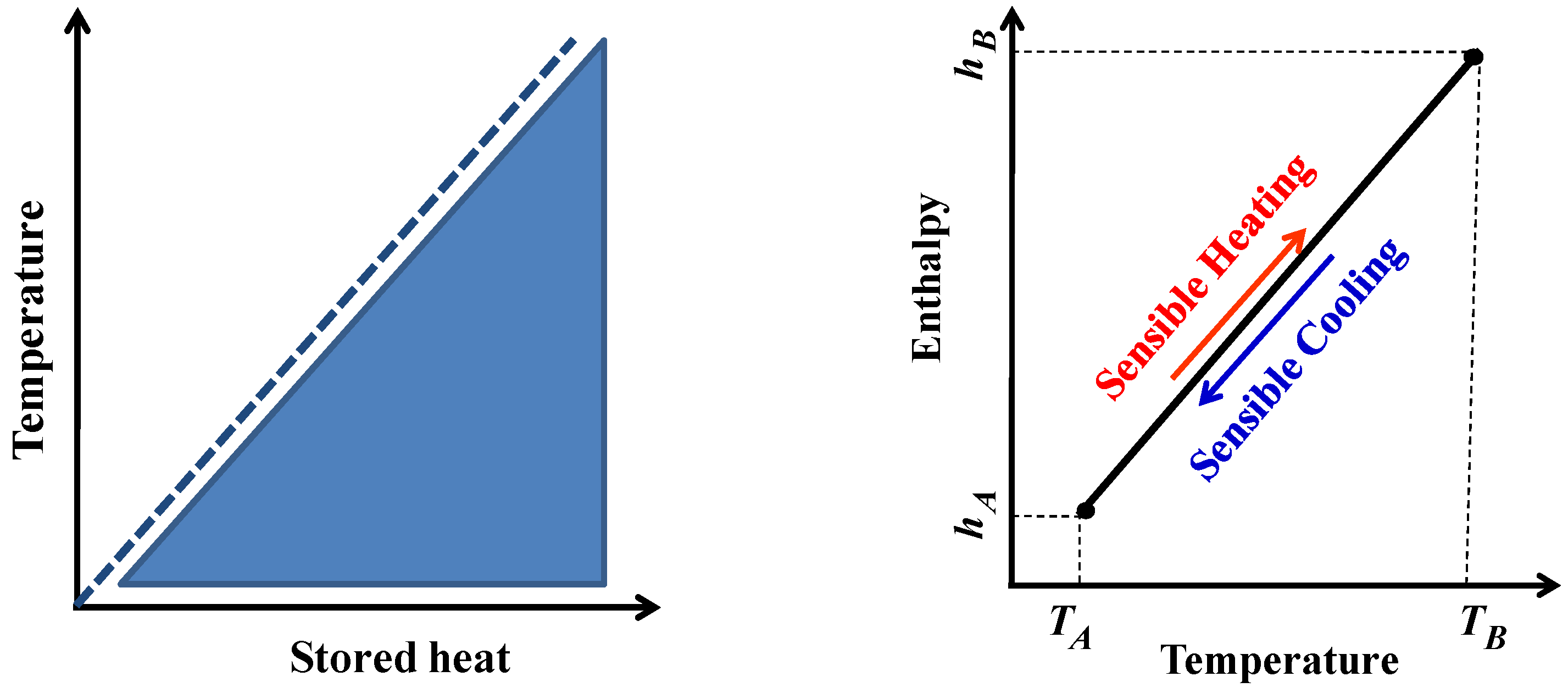
2. Sensible Heat Storage (SHS) Method

Sensible heat storage (SHS) is the most traditional, mature and widely applied TES solution due to its simple operation and reasonable cost. However, it suffers from the low-energy storage density achieved compared to the other two TES options, viz LHS and TCHS [27]. In this approach, the energy transfer (as heat) to and from the storage medium that can be liquid (water, oil, etc.) or solid (sand, rock beds, brick, etc.) results in the corresponding change (increase or decrease) of the medium’s temperature. Figure 4 depicts the SHS typical diagram during sensible heating or cooling with no phase transition during the process [3,28]. One of the advantages of this mode is that the storage and release of the accumulated heat (charging and discharging cycles) can be repeated without any problem while involving a large volume to meet the needs [29]. In addition, this method generally takes the advantage of certain properties of the storage material such as its high specific heat [30].
Since the quantity of sensible heat stored (Q) depends on the mass (m), the heat capacity ( C p ) [30], two main characteristics of SHS materials (SHSMs) should be pursued to increase the capacity storage volume (MJ·m−3) with high specific heat and density. Among the abundantly available materials, water has a comparably high specific heat and density, wherefore it is quite frequently used as a storage material in many practical applications. For example, the sensible heat storage capacity has been estimated at 250 MJ·m−3 for a thermal gradient of 60 °C in the case of water [18].
Fernández et al. [31] presented a bar chart where a certain property (e.g., specific heat capacity) is plotted for all families of engineering materials mostly used in SHSMs to better identify and classify them. On the other hand, thermal conductivity, thermal diffusivity and flow rate play a key role in charging/discharging cycles that ensure stratification ability.
It is worth noting that a high thermal stratification facilitates the release of heat, allowing a transfer of thermal energy at low temperature toward the colder zones during the charging period, and thereby, a higher exergy (quality energy) which is promptly obtained from the hottest zones during the discharge process [32]. The thermal effusivity parameter appears as the main variable influencing thermal inertia in passive construction applications [33]. This parameter characterizes the rate at which a material can release or absorb heat, where its raise augments the heat stored quantity and thereby mitigates energy consumption [18]. In addition, the availability, cost, toxicity and volume change are further criteria for the selection of sustainable SHSMs [18]. As mentioned before, the main disadvantages are their limited energy density and the device self-discharge [34]. To assess the SHS system performance, González-Roubaud et al. [35] pointed out that the relevant quantities are energy storage capacity, power, efficiency, time of charging/discharging cycles and cost.
According to Cabeza et al. [26], the SHS approach has been widely used in solar applications such as concentrated solar power plants (CSP) [36] or desalination [37]. For example, the water-based SHS is one of the most widely used solar TES systems in residential applications (see sketch in Figure 5) [3], and besides, Koçak et al. [38] have published a comprehensive review article on SHS systems and materials available and applied in industrial solar heat applications. According to the temperature range, they pointed out that there are mainly three groups of solar industrial processes, viz low-temperature (<150 °C), medium-temperature (150 °C < T < 400 °C) and high-temperature (>400 °C) applications. They concluded that the fixed-bed thermocline technique is the most economical and widely used method for sustainable solar applications, regardless of the temperature range. SHS technologies are gathered in Table 3.
It is noteworthy that numerical studies and experiments are increasingly performed to define optimal parameters to improve the system’s performance.

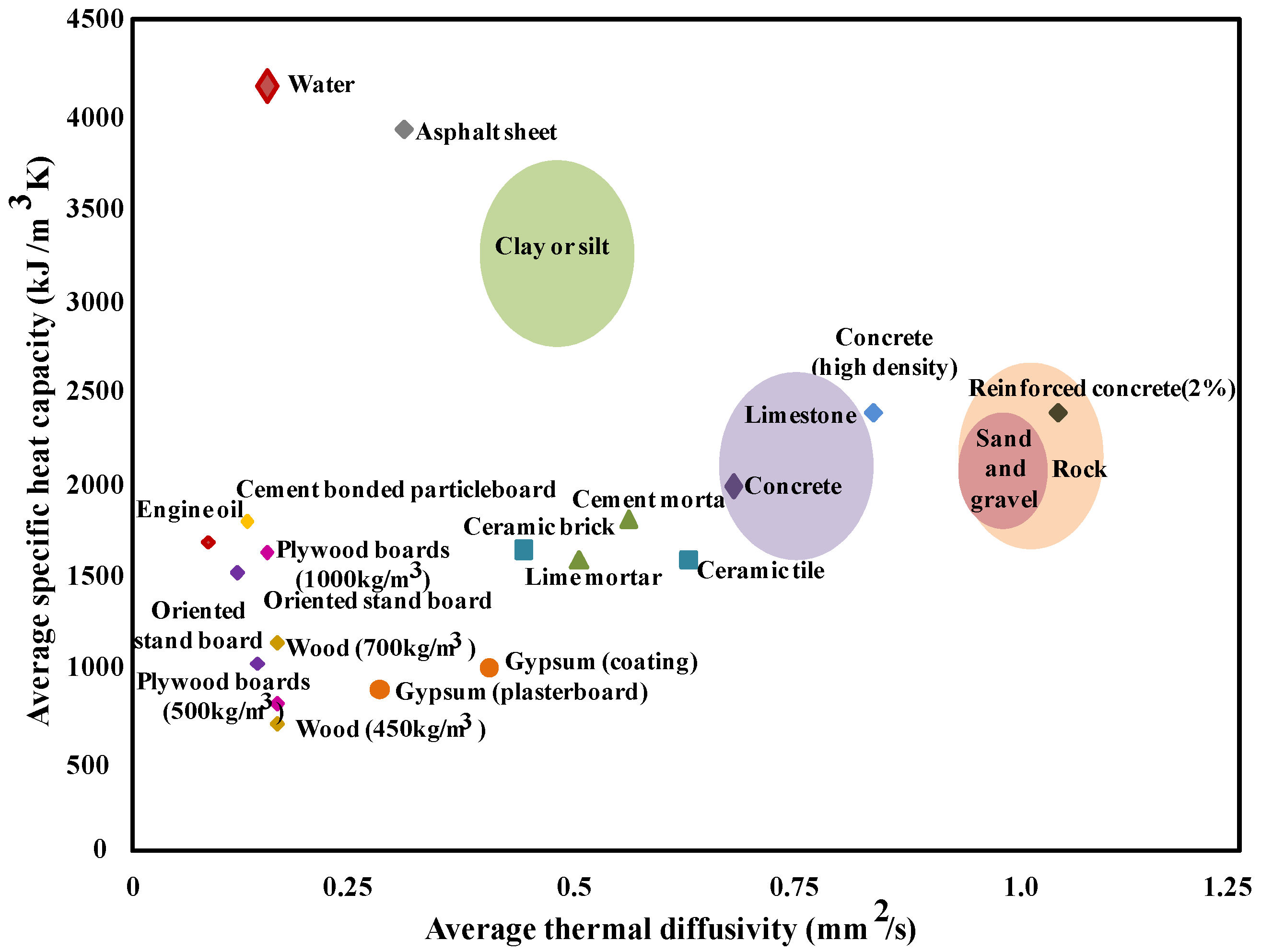
2.1. Sensible Heat Storage Materials (SHSMs)

There are different reviews on TES solutions dealing with the thermophysical characteristics of commonly used SHSMs and comparing the different parameters involved (such as physical, chemical, thermal, environmental, economic, etc.) to fulfill construction requirements and/or industrial applications. The SHSMs can be classified into solid and liquid storage materials [3,18]; regarding liquid heat storage materials, the most common materials are water, oils, and pure alcohol or its derivatives, while rocks, stones, bricks, concrete, dry and wet soils, wood, plasterboard and cork are the most commonly used as solid heat storage materials.
Fernández et al. [31] presented an overview of SHSMs in the temperature range of 150–200 °C leaning on Ashby’s method [39,40] for material selection to find suitable and potential materials for long and short-term cycles for the SHS method. According to these authors, solid SHSMs can be classified into metals and alloys, ceramics and glasses, polymers and elastomers, and hybrids. The thermophysical properties of some commonly used SHSMs are listed in Table 4 [3,18,19,41].
Note that many factors must be ensured to guarantee a long life of SHSMs such as thermal and chemical stability (constant thermal properties, no chemical decomposition and no degradation) at high temperature gradient regardless of the number of cycles (charge/discharge). According to Klein et al. [42], storage substances should conduct heat better, have higher specific heat and density, be able to operate in a suitable temperature range and be easily accessible in terms of cost. Figure 6 displays the average volumetric specific heat capacity vs. average thermal diffusivity for the most available SHSMs [18].
Today, the number of the available SHSMs (either liquids or solids) for engineering purposes exceeds 150,000 [28,31]. Among them, water is the most mature material due to its availability, non-toxicity, low cost and high specific heat capacity [28].
Almendros-Ibáñez et al. [43] performed a synthesis study on different techniques for storing solar energy in particle beds, emphasizing the different particle methods called packed beds and fluidized beds. They stated that liquid SHSMs have a higher specific heat capacity than solids (e.g., rock). Unfortunately, some issues such as liquid storage infrastructure, high cost of heat exchangers, risk of leaks and large storage tanks (hot and cold) limit their use [18,44,45,46]. On the other hand, concerning solids SHSMs, their main disadvantages are the low density, the high investment cost and the risk of self-discharge (in the long term).

2.2. Sensible Heat Storage in Porous Media

Without detailing, the SHS mode consists of a sensible heat storage material (SHSM), an SHSM container (e.g., tank) to prevent leakage and heat losses and input/output devices [47].Among the tools used in this storage mode, SHS in a porous medium is the most preferred solution. Out of the available case studies in the literature in this field, a few representative ones are reviewed in the present section. Saturated tanks of porous solid SHSMs are used in many industrial and building applications such as power generation and heating [3]. Figure 7 exemplifies a residential heating application using a porous fixed bed storage tank. In general, a fixed bed storage tank is used for the TES of solar air heaters and represents a volume of porous medium formed by packing particles of selected SHSM into a container. In this system, the working fluid (e.g., air) advects heat from the collector to the reservoir. Hot fluid passes through spaces between solid SHSMs (e.g., rock or sand), causing the particles to rise in temperature during the day (charging loop), and the quantity of sensible heat stored inside the tank is recovered during the night (discharging loop).
Let us point out, however, that the main parameters that influence the SHS system performance are the working fluid type, the flow rate and the porosity [3,47].
A huge range of investigations in the literature have dealt with SHS in various porous units. Among the different characteristics of a sensible storage medium, the porosity effect, which turned out to be a crucial characteristic, is sketched herein. To address this topic, Mabrouk et al. [48] developed a numerical model to study the effect of pore density parameter (PPI) on an SHS unit. The system deemed was subjected to forced convection and compared to an LHS unit. They advised a porous metal foam to optimize energy and exergy efficiencies while indicating that increasing the PPI for high porosity value mitigates energy losses for sensible heat systems and thereby increases the quality of stored energy. In another study, Amami et al. [49] explored the charging and discharging process enhancement in a porous SHS duct held under a forced pulsating flow. They examined several porosities of the porous support while estimating its thermal performance. They found that with increasing porosity, the sensible energy amount stored is improved, and the exergy efficiency (quality) is significantly raised. As an example, the energy efficiency increased from 31% to 68.2% when the porosity increased from 0.6 to 0.8, respectively, for a given flow pulsation amplitude. The same shall apply to exergy efficiency, which goes from 32.4% (for ε = 0.6 ) to 67% (for ε = 0.8 ).
Elouali et al. [44] achieved four physical models through numerical simulations to describe the thermal behavior of a packed bed for sensible heat storage. They particularly discussed the porosity influence on the packed bed during charging and discharging periods. They demonstrated that a decrease in porosity improves the thermal storage capacity of the packed bed and increases the interstitial heat transfer between the coolant and the solid particles. Furthermore, they noted that high porosity slows down the charging process.
Kasaeian et al. [50] presented a review of numerous models to simulate nanofluid flow physics in a porous medium. They gathered details on the main features of a porous structure embedded in thermal systems such as heat exchangers and ducts. They stated that the use of a porous matrix extends the specific interface area between the porous structure and the working fluid, which results in a higher rate of heat transfer and, thereby, significantly improves the system thermal efficiency.
Sheremet et al. [51] conducted a numerical analysis of natural convection in a concentric horizontal annulus filled with a porous structure saturated by Cu-water nanofluid. It turned out that a low porosity ( ε < 0.5 ) increases the thermal conductivity of the medium, and it has no effect on the flow of the fluid nor on the heat transfer. On the other hand, they found out that a large porosity ( ε > 0.5 ) intensifies the convective flow. In 2015, Sheremet et al. [52] numerically examined the thermal behavior of a square cavity composed of solid porous medium (aluminum foam and glass beads). They targeted the effects of pore morphological parameters such as porosity. The authors noted that the local and mean Nusselt numbers are minimum at high porosity, and the latter significantly affects the heat transfer rate.
In 2014, Amami et al. [53] proposed a porous unit designed to store sensible heat. They demonstrated that the use of a porous medium with high permeability and low thermophysical properties improves the performance of the considered TES unit and raises temperature and the stored sensible energy amount.
Heap et al. [54] discussed the influence of volcanic rock porosity and magma (SHSM). They indicated that an increase in porosity decreases the density and compressive strength of rocks while increasing their deformability. Thereby, they advised adopting a low porosity. Dhifaoui et al. [55] conducted an experimental study of SHS performance of a vertical porous bed composed of glass beads and air which is heated with a constant heat flow.

3. Latent Heat Storage (LHS) Method

Latent heat storage is based on the amount of energy absorbed or released during the reforming of the phase structure of a phase change material (PCM) from one physical state to another during the phenomena of melting, solidification, gasification and liquefaction [19,27,56,57]. Due to its high thermal energy storage density and nearly constant working temperatures, latent heat storage (LHS) technology has become a good solution for correcting the mismatch between energy supply and demand. At the start of the charging process, the temperature of the latent heat storage material evolves as it absorbs thermal energy, and when it reaches a specific range, the material begins to change the phase while storing heat. However, during the discharge period, the PCM switches to its initial state by releasing thermal energy. Unlike SHS, the phase transition process unfolds at a nearly constant temperature characteristic of the material physical state change [19,57].
The heat storage capacity (Q) of an LHS system typically consists of two parts sensible heat (before and after the phase transition) and one part latent heat (during the phase transition) [3,19,27,58]:
Q = T 1 T m m c p d T S e n s i b l e   h e a t + m Δ h L a t e n t   h e a t + T m T 2 m c p d T S e n s i b l e   h e a t
where the mass (m), specific heat capacity ( c p ) and temperature (T) are the properties of the PCM. m Δ h is its latent heat. The indices 1, 2 and m indicate the initial, final and melting temperature, respectively.
Recall that during the phase change operation, the temperature remains roughly constant with small volume changes, making the phenomenon simple and safe. The typical diagram of LHS is illustrated in Figure 8 [3,28].
The phase change process takes place in a temperature range between a solidus temperature, T s (the first solid melts (melting process)/the first solid forms (start solidification process)), and a liquidus temperature, T l (the last solid melts (end of melting)/the last solid forms (solidification end)). In this context, Saffari et al. [59] defined two cooling/heating PCM temperature ranges to minimize the annual energy consumption. During cooling, the maximum melting temperature of PCM is about 26 °C (melting range 24–28 °C), while during heating, the minimum melting temperature of PCM is about 20 °C (melting range 18–22 °C).
As depicted, the PCM stores sensible heat when the PCMs temperature is outside the phase change temperature range and latent heat when its temperature reaches the phase change temperature. Moreover, the different phase changes in LHS can be in solid–solid, solid–liquid, liquid–solid, solid–gas, gas–solid, liquid–gas and gas–liquid forms.
In the case of a solid–solid transformation, the crystalline structure of the material changes and continues to store heat [34,60]. Generally, such a phase is characterized by low amounts of latent heat and volume changes compared to solid–liquid processes. For this process, organic solids such as pentaglycine, pentaerythritol, Li2SO4 and KHF2 [60,61] were able to open up interesting opportunities. Leaks and encapsulation absence and a more flexible design are their main advantages [62,63]. On the other hand, during solid–gas and liquid–gas transformations, a large quantity of latent heat can be acquired requiring large capacity containers due to the significant change in volume. Thereby, this solution is less usable for the building’s thermal comfort [64]. For the sake of brevity, solid–liquid phase change processes remain economically competitive with other LHS solutions [64].
On another aspect, the advantages of LHS mode over SHS mode can be listed as follows:
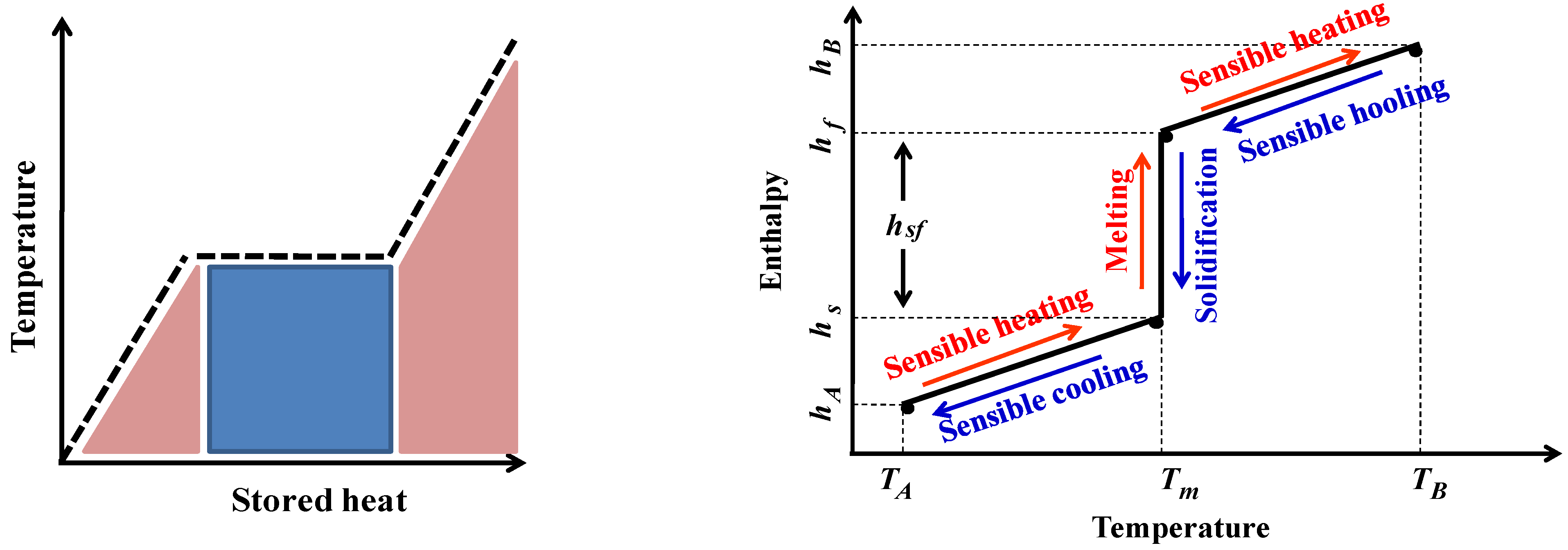
  • The phase change enthalpy of PCMs is much higher than the sensible heat;
  • LHS materials (PCM) have a storage density that can be five to 14 times greater than that of SHS materials [60];
  • The LHS method takes place in a quasi-isothermal manner unlike the SHS process where the materials temperature is too high;
  • SHS systems using rocks (resp. water) require three times (resp. 1.5 times) more volume than LHS systems using paraffin wax [34];
  • Seasonal overheating problems can be avoided in LHS systems due to the involved low mass.
However, the low thermal conductivity, low thermal stability of PCMs under long-term cycles, problems with supercooling, subcooling, phase segregation (e.g., salt hydrates) and cost are the main obstacles to the development of the LHS materials sector [3,58,65,66,67,68,69].
Supercooling, phase segregation, convection and impurities problems are encountered in PCMs such as hydrated salts, octadecane, etc. During the cooling process, the substance temperature drops below the melting range ( T P C M T m e l t i n g ) without starting the solidification mode. Thereby, nucleation is triggered, causing a sudden rise in temperature to the melting point. Under supercooling, the onset of solidification is delayed, and the liquid solidifies at a temperature under its freezing temperature, causing a lag between the design and the real behavior of the considered PCM. Likewise, in case of ignorance or overestimation of supercooling, experimentation and numerical simulation exhibit a time lag [70,71]. Figure 9 illustrates the supercooling of a PCM [72].
Indeed, the supercooling phenomenon maintains the liquid state of a PCM at a temperature below its solidification temperature and prevents the release of latent heat at a temperature gradient Δ T . Note that the technique of adding nanoparticles to PCMs to form a nanofluid has been suggested as a suitable solution to alleviate the supercooling problem. To the best of our knowledge, Liu et al. [73] analyzed the graphene oxide nanosheets as an additive component for the PCM–water. They found that the supercool-ing temperature can be decreased by 69% for deionized water. Incomplete melting (during the charging period), PCM containers with isolated parts (called cold fingers), excitation by vibrations, magnetic and/or electric fields and ultrasound among many others could be solutions to handle supercooling and overcome the problems caused.
Phase segregation represents another crucial issue of some PCMs, in particular salt hydrates. It consists of a separation of phases causing an accumulation of the dense phase as seen in Figure 10 [3]. Therefore, the PCM split into different phases loses its expected characteristics and cannot be used in an LHS application. In this context, thickeners are the most commonly used solutions to avoid phase segregation.

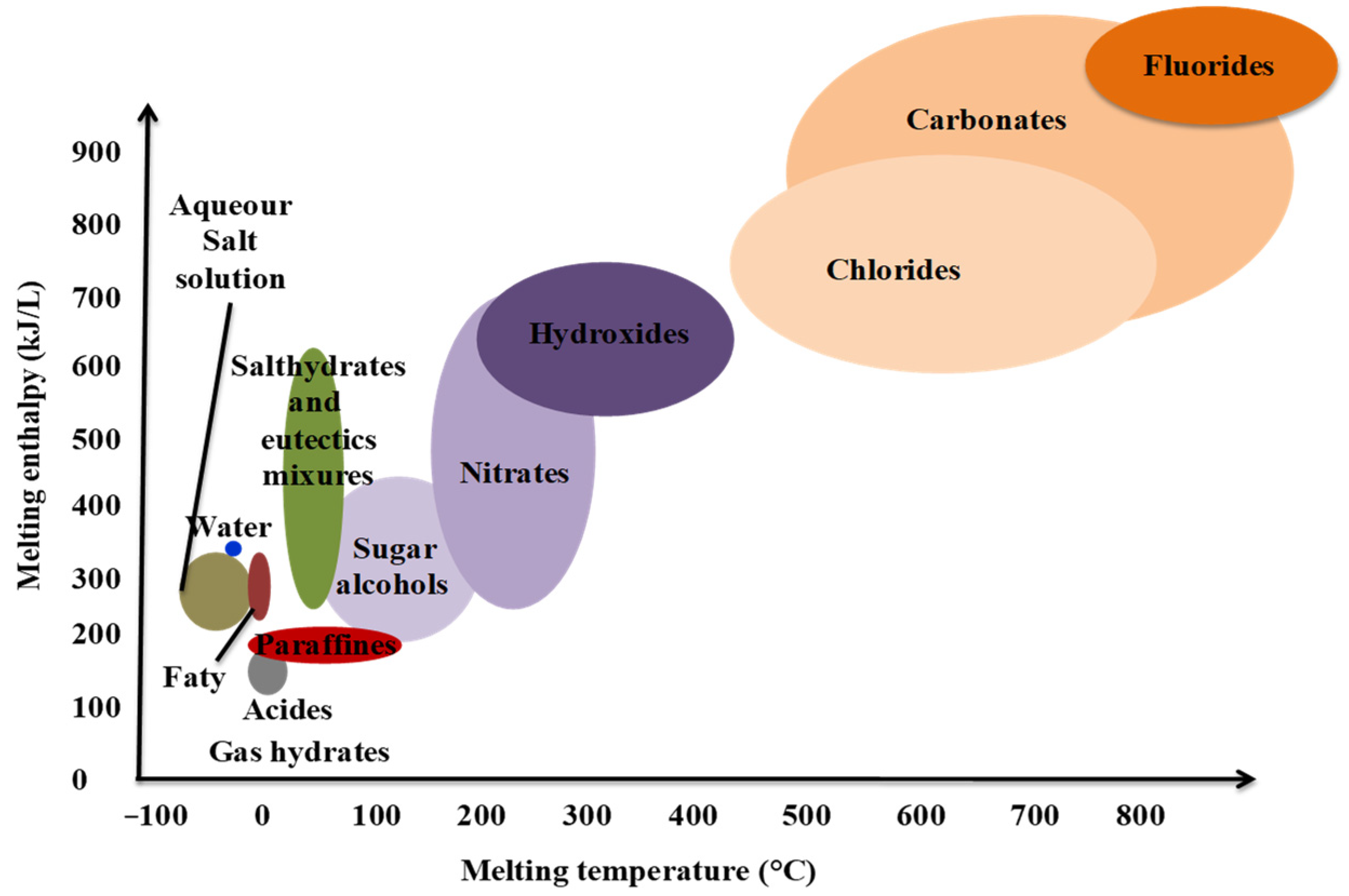
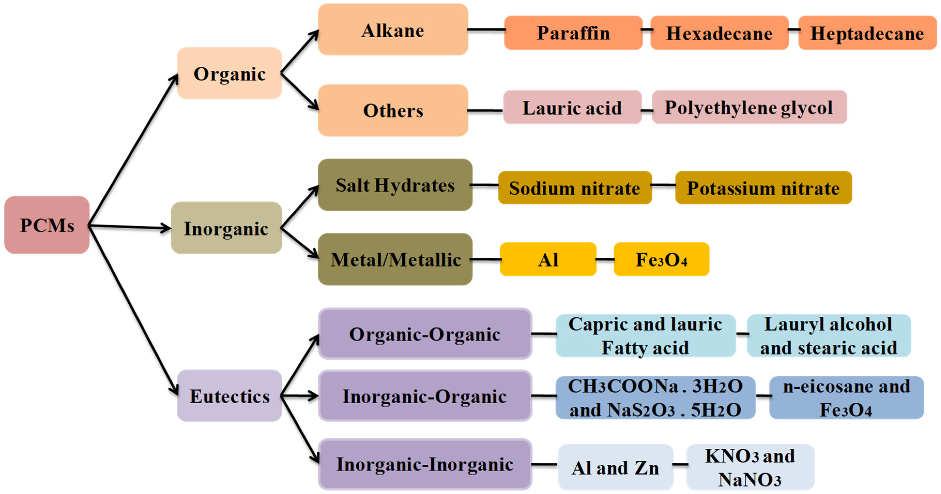
3.1. Latent Heat Storage Materials (LHSMs or PCMs)

Since PCM is the central ingredient (component) of an LHS system, it is expected to meet certain requirements to improve energy storage density and ensure thermal stability under long and/or short term loops. Its sound selection is based on its main desired thermophysical, kinetic, chemical, economic and environmental characteristics. These have been listed by Sharma et al. [60] and Nomura et al. [74] as follows:
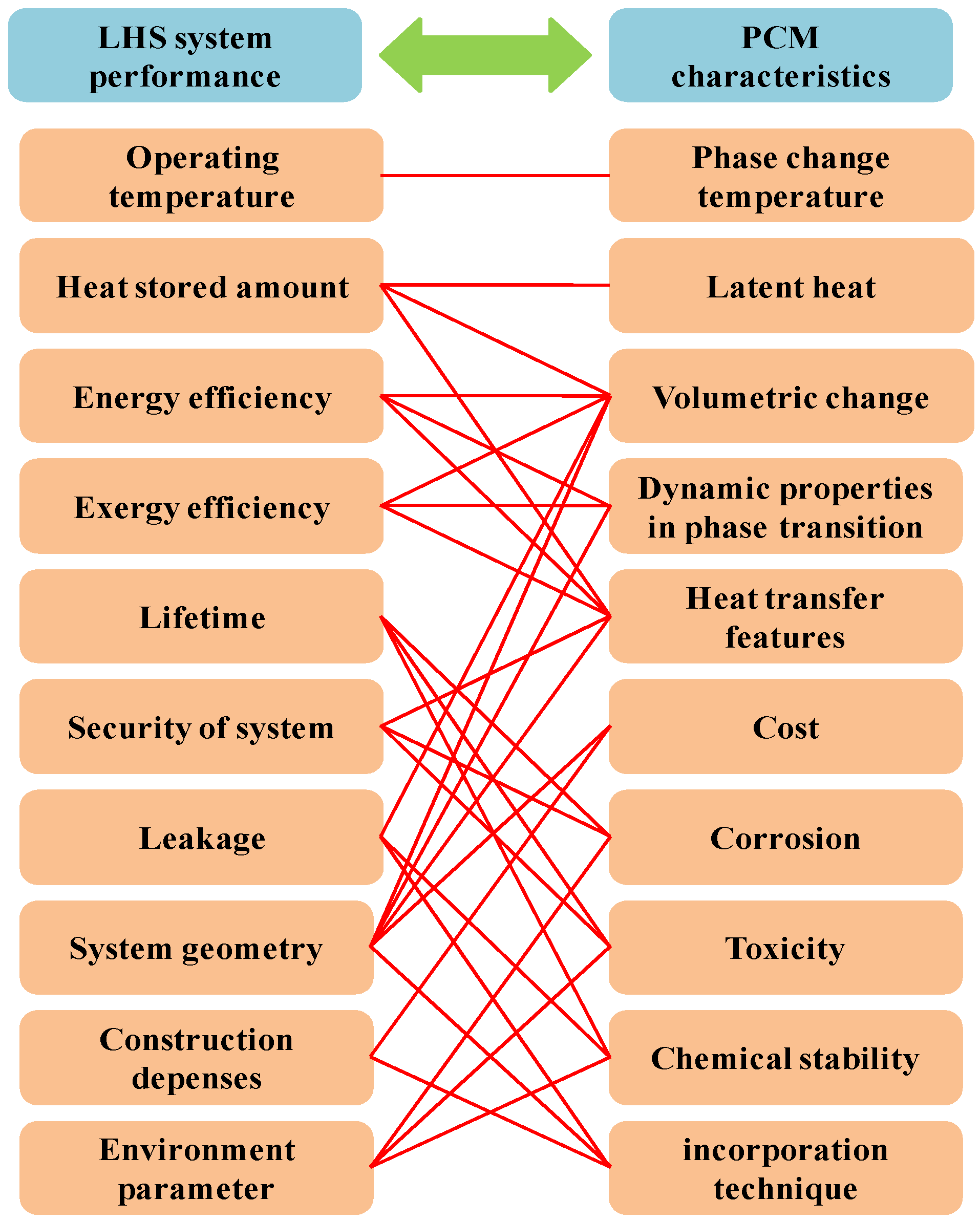
  • In terms of thermal properties, the PCM must have a phase change temperature corresponding to the operating temperature of the LHS application. Moreover, it must have a latent heat and a specific heat. PCMs with high thermal conductivity are advocated to facilitate phase transition and interstitial heat transfer;
  • Regarding physical properties, PCMs should exhibit large density, small volume changes and low vapor pressure during the phase transition process while respecting the operating temperature range to limit containment issues;
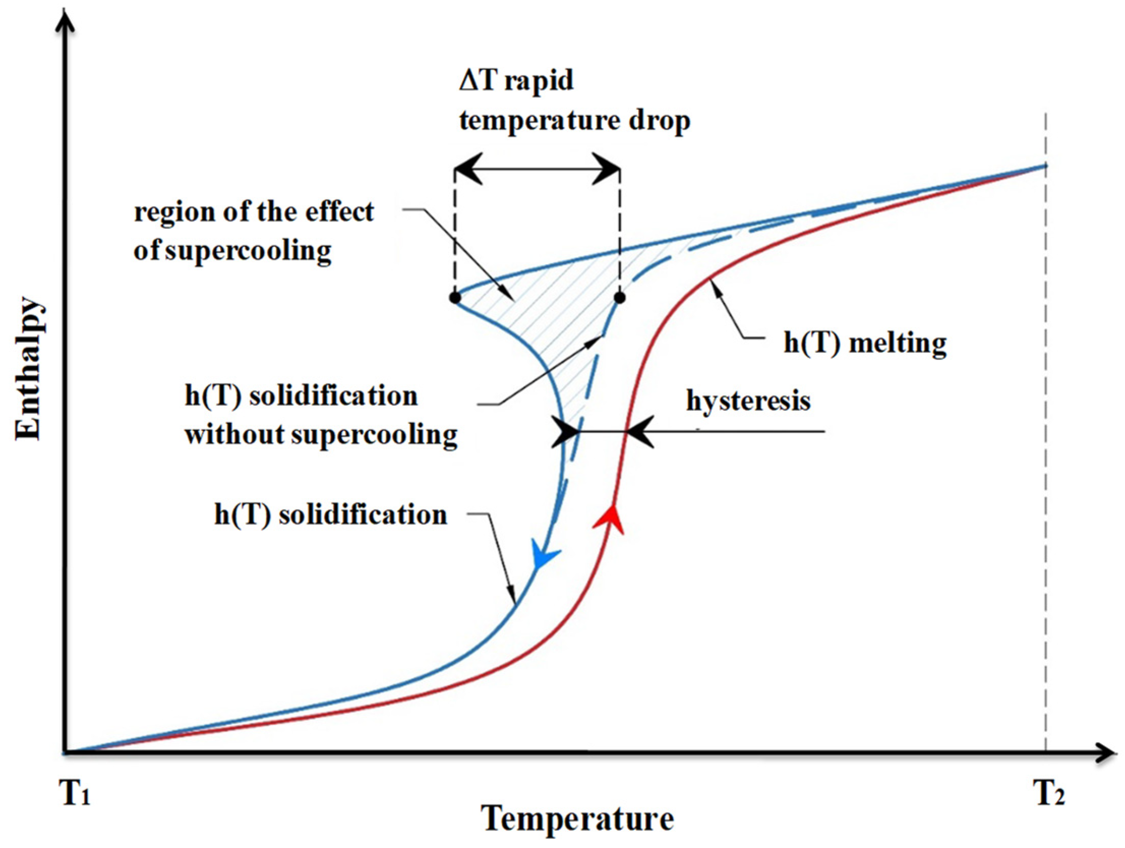
  • As for kinetics properties, subcooling and supercooling should be avoided, and a sufficient crystallization rate should be achieved;
  • For chemical properties, PCMs should be compatible with the materials in the application. They should retain their chemical stability for long-term cycles (no chemical degradation and breakdown). In addition, the latent heat storage material should be a non-toxic, non-flammable, non-corrosive, and even less explosive substance. Moreover, charging and discharging periods must be fully completed;
  • Low-cost PCMs should be preferred in terms of economic properties.
For environmental properties, PCMs should have a low environment impact by being non-polluting and recyclable. Unfortunately, each PCM has its own characteristics that make it virtually difficult to provide a clear answer to all the listed criteria.
As tacitly stated above, PCMs can be split into PCM solid/solid, PCM solid–liquid, PCM solid/gas and PCM liquid–gas. It is solid–liquid PCMs that are involved in this section and can be divided into organic, inorganic and eutectic, as depicted in Figure 11 [3,20,24,75,76,77]. In addition, an attempt to compare the groups that have been up-cited is provided in Table 5 [24,77].
It is worth noting the PCMs’ use has spread to various industrial sectors such as textiles, satellites, telecommunications and medicine thanks to the change in their physical states. For moderate melting temperatures (below 15 °C), PCMs are best suited for air conditioning and extreme cooling applications where the operating temperature matches that of melting. On the other hand, for extreme melting temperatures (above 90 °C), PCMs are used to prevent a sudden temperature rise which can cause fires [78,79,80,81,82].
Figure 12 portrays the enthalpy of fusion vs. the melting temperature of some existing PCMs [77,78,82,83,84]. Close examination of such a figure indicates that suitable PCMs for construction applications are those with a phase temperature between 18 and 40 °C. Simply put, potential PCMs for building applications are paraffin, fatty acids, salt hydrates and eutectic mixtures. These are used (a) as passive thermal storage integrated within building elements, and (b) as independent storage units coupled with heating, ventilation and air conditioning (HVAC) systems.
From an energy consumption point of view, PCMs are widely applied in building applications (around 40%) and the industrial sector (around 55%). The rise of these materials will take on its full importance when raising awareness of recycling and optimizing energy consumption are the challenging tasks [85,86]. Indeed, more and more efforts in buildings are directed to achieve comfortable conditions in terms of the living environment. These efforts remain linked to the (high) costs and increased use of PCMs, and they can lead to environmental pollution. In addition, controlling energy consumption appears to be an innovative way to limit energy consumption and environmental pollutants [87,88,89,90,91]. In recent years, PCMs and energy storage technologies are among the tools that have become increasingly important in buildings’ energy management. In this field, Faraj et al. [85] discussed a fairly comprehensive literature on TES with a focus on PCMs for building applications such as cooling, heating and hybrid applications. They exhibited the active and passive processes while providing a summary of the PCMs used, their characteristics, and their incorporation techniques. Theyconcluded that the use of PCM reduces energy consumption for heating, ventilation and air conditioning in the active system as well as ceilings in the passive system; however, the main disadvantage isincomplete solidification during the night for the cooling systems. Another review on the use of PCMs for cooling building applications was carried out by Souayfane et al. [92]. They presented and discussed several cooling applications based on PCM integration such as solar cooling systems, free cooling, evaporative and radiative cooling systems, air conditioning systems, and PCMs active and passive systems application in building envelopes. The authors dealt with the selection criteria of PCMs and concluded that the PCMs incorporation reduces energy consumption while ensuring thermal comfort and mitigating temperature fluctuations. They did, however, report many drawbacks such as low convective heat transfer coefficients, considerable portions of PCM used, incomplete cycle of the PCM solidification process at night, and limited interstitial heat transfer between the PCM and the heat transfer fluid. So, it has been claimed that active systems using paraffin can handle the problem of poor convective heat transfer. It should be noted that several studies have reported that organic solid–liquid PCMs are the most used substances where paraffin waxes represent a good share (about 27%) for applications as PCMs [82,93,94,95].
Figure 13 exhibits the relationship between the PCMs’ properties and LHS devices’ performance. As can be seen in the figure (supported by different investigations in the literature on this topic), PCMs have a strong influence on the LHS systems’ thermal performances [3].
In addition, let us point out that a PCM is suitable for applications if its properties do not degrade after a certain number of repeated cycles, i.e., if it remains stable in cycling and in the long term [96]. Having said this, the economic aspect remains a crucial factor in the MCP choice [60,87,97].
Note that the integration of PCMs can be completed via many techniques including the direct integration of PCM (liquid or powder (such as gypsum, concrete, plaster, etc.) mixed with other materials), incorporation in porous structures, shape stabilization and macro-encapsulation or micro-encapsulation or even nano-encapsulation approaches [85]. Encapsulation techniques help to increase the interstitial surface area, to prevent thermal losses and to limit the direct exposure of PCMs to the environment. In some cases, this method is used to improve the thermal conductivity or to preserve the PCM morphology during the phase change. Generally, capsules (containers) are made of polymer or metal [77,98,99,100,101].
To the best of our knowledge, the micro-encapsulation technique was first conducted by Umair [93], and it is widely applied in building and textile industries for thermal regulation. On the other hand, the first experimental study on solid–liquid phase change heat transfer of porous form stabilized PCM was developed by Weaver and Viskanta [102] using water and glass as embedded PCM in a porous matrix.
Figure 14 shows some methods of integrating PCMs [20,103,104,105].

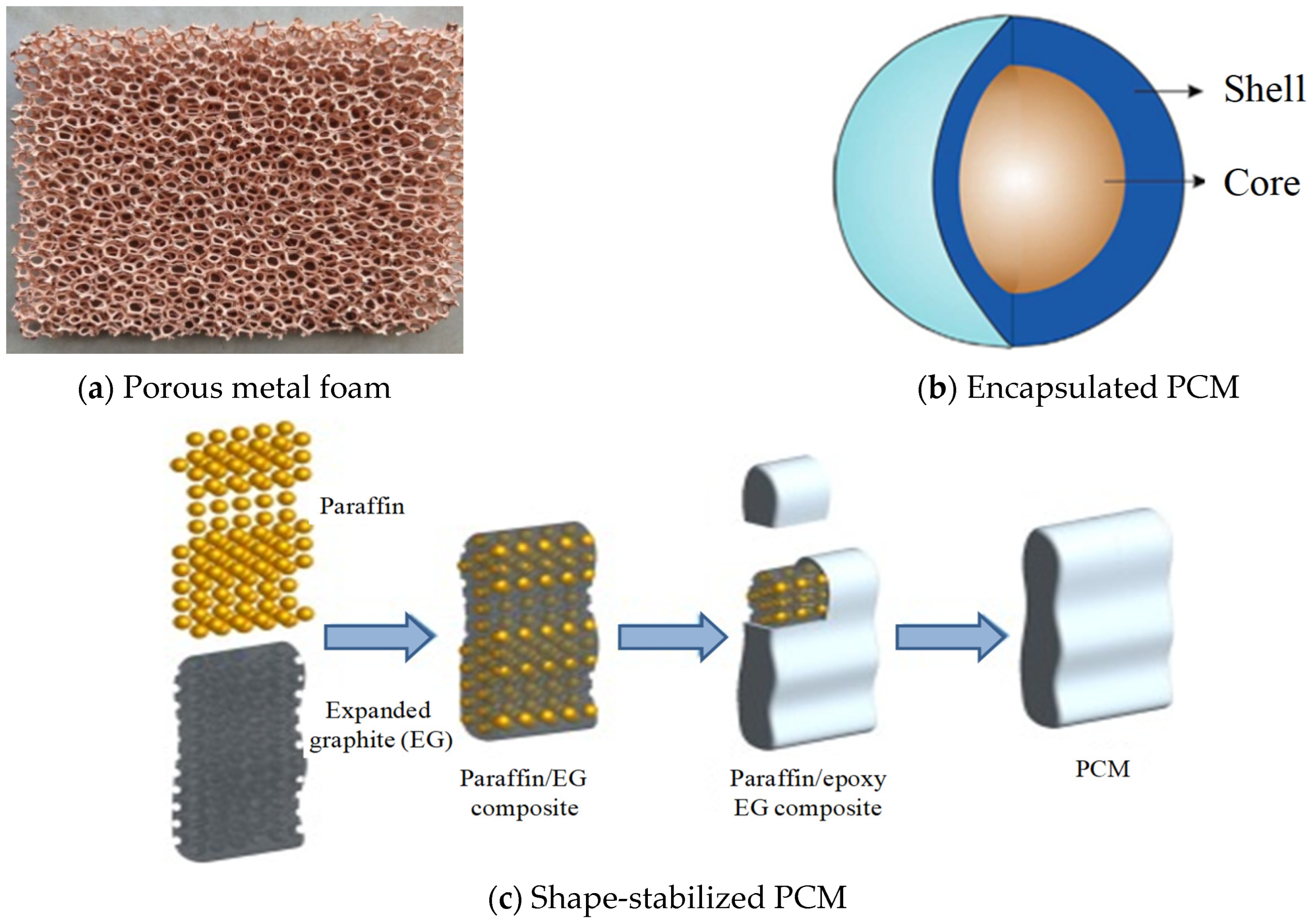
3.2. Latent Heat Storage in Porous Medium

It has been mentioned many times that most pure PCMs exhibit low thermal conductivity, which limits their use in many fields [105]. To deal with this problem, solutions have been proposed:
  • Manufacture of a composite by associating a PCM and a porous matrix (metal foam or expanded graphite) [106];
  • Addition of metal spheres, fins and wools to form a new MCP with improved thermal conductivity [107,108,109];
  • Implementation of nanomaterials [110,111,112].
Porous supports can be classified according to their pore size into macro-porous (>50 nm), mesoporous ( 2 50   nm ), and microporous (<2 nm) [113].
Figure 15 depicts the most used porous supports [114,115] that can be used as heat transfer promoters due to their large interstitial surface. Meso and microporous media exhibit excellent guest–host interaction while preventing leakage. In hierarchical porous forms, macro-pores store PCMs in a cavity. As for mesopores, they provide transport pathways, while micropores block the movement of PCMs by exerting capillary forces.
The impregnation of PCMs with a porous structure consists of the manufacture of a porous medium (copper, aluminum, graphite, metallic foam, etc.) in the form of a solid matrix having interconnected or disconnected voids called pores where the PCM is embedded for the latent heat storage. It has been reported that at the nano or microscale, PCMs can retain their original shape without any leakage during phase transition due to capillary and surface tension forces [28,74]. Moreover, performance enhancement depends on the morphology and the properties of the structure such as porosity, pore density and thermal conductivity [28,116,117]. In this context, Mabrouk et al. [118] numerically studied the laminar phase change process of a PCM in an open-ended porous channel filled with porous metal foam. They found that the melting rate intensifies as porosity decreases and Reynolds number (Re) number increases, and they noted that the thermal performance improves significantly at low porosities. Following a similar idea, these authors numerically investigated the effect of pore morphological parameters such as pore per inch (PPI) density and porosity of a metal foam/paraffin composite on the heat transfer mechanisms involved during the phenomena of melting/solidification [119]. They demonstrated that increasing Re with high PPI and porosity reduces the melting time, while it is slowed down with low PPI and porosity.
Along the same lines, Yang et al. [120] proposed a new LHS system filled with porous metal foams with positive and negative gradients in pore parameters to improve the thermal performance. They found that an almost 18% reduction in time to complete melting can be achieved with positive gradients porosity design, while an increase of around 36% can be achieved with negative gradients. To cope with the low thermal conductivity issue, Li et al. [121] developed a physical and numerical model to examine the effect of metal foam porosity and nanoparticle concentration on an LHS device where PCMs are embedded. They pointed out that a 83.7/88.2% reduction in melting/solidification time is achieved with the addition of 95% porous metal foam, while a decrease of 25.9/28.2% is secured by adding 5% copper nanoparticles. Sardari et al. [122] investigated the copper metal foams’ porosity effect on the melting process and stated that low porosity improves the system performance compared to higher porosity. However, pore size has no effect. For their part, Yang et al. [123] conducted an experimental and numerical survey on the solidification performance of impregnated PCMs into a metallic structure. The effects of porosity and pore density have been targeted. They reported that the complete solidification time with a porosity of 0.93 and 0.97 can be reduced by 87.5% and 76.7%, respectively, while at low porosity, the melting/solidification rate rises. In addition, they confirmed that the addition of the metal foam effectively improves the thermal conductivity of the composite media involved. Zhang et al. [124] implemented an experimental and numerical study on the behavior of a copper foam/paraffin composite during the melting process. Compared to pure paraffin, the fusion rate has been significantly improved due to the high thermal conductivity gained. Moreover, Atal et al. [125] experimentally reported on the porosity effect of the aluminum metal foam in an LHS unit and pointed out that small porosities could reduce the phase transition time. Note that the improvement of thermal performance [65,126] has been proven by decreasing the pore size, while Refs. [127,128] have rather shown a negative effect.

4. Latent Heat Storage (LHS) vs. Sensible Heat Storage (SHS)

Using the bibliometric analysis method, Cabeza et al. [26] reported that up to 2021, more than 27,016 TES-themed articles have been published in the literature. Explicitly, nearly 2900 articles dealt with the SHS, while a record number of around 12,152 concerned the LHS subject matter.
Table 6 sets out a non-exhaustive comparison between the SHS and LHS techniques in terms of operating principle, advantages, most used materials and application domains [5,60,114].
Zhao et al. [27] drew up and analyzed the technical parameters characterizing SHS and LHS (see Table 7).
Faraj et al. [85] published a critical paper on the use of PCMs for cooling applications in buildings. It was noted that LHSMs store between five and 14 times more energy than SHSMs [129] and that certain materials (e.g., rocks) offer much higher storage volumes than that of certain organic or inorganic PCMs.

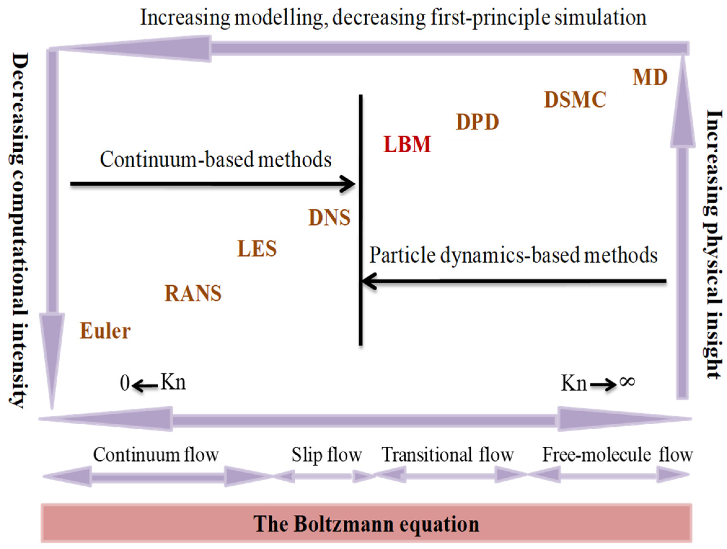
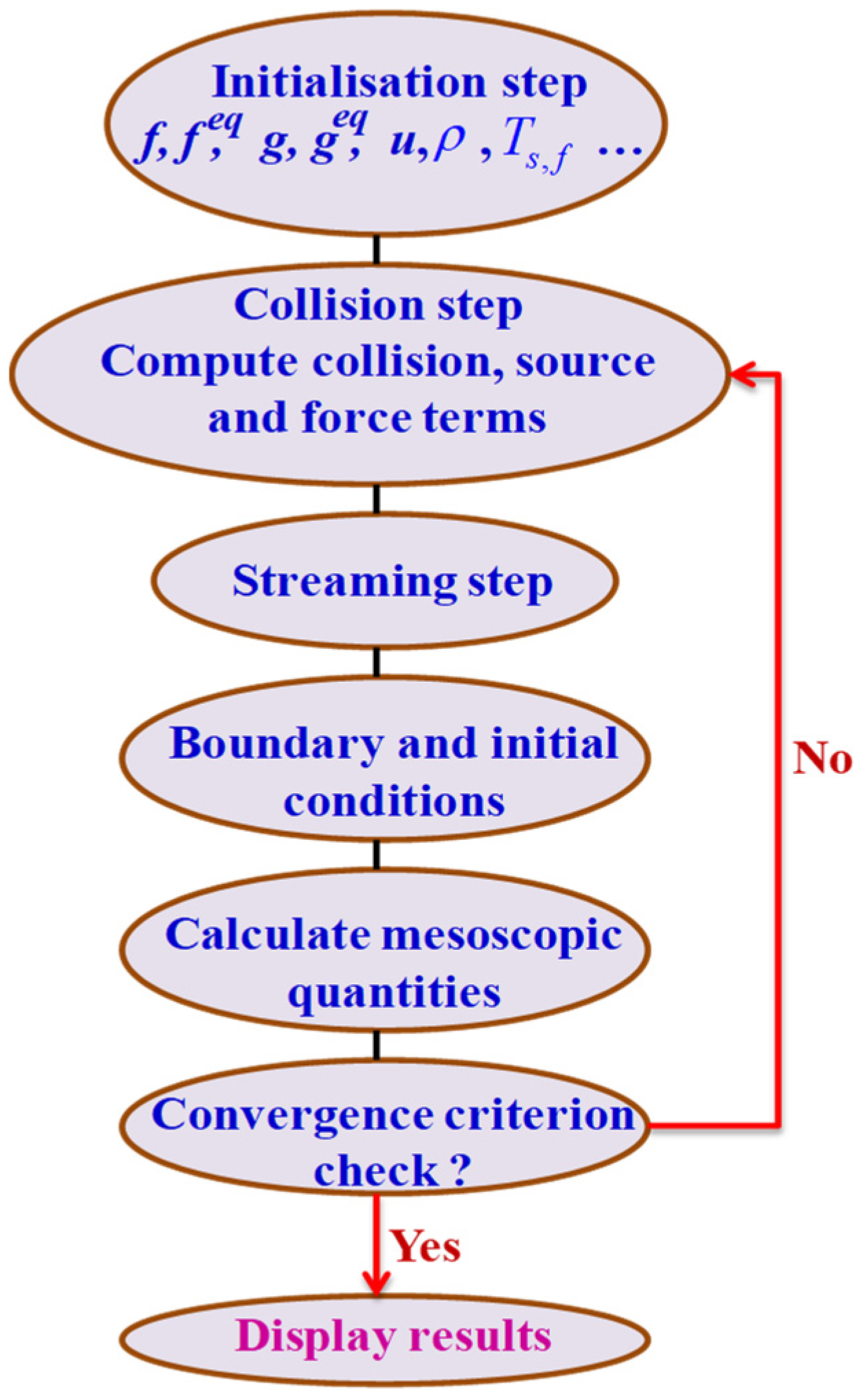
5. Lattice Boltzmann Methods (LBMs)

Due to the limited capacity for theoretical analysis, huge cost, and long periods of experimental investigation, numerical simulation has emerged as an effective alternative tool for various industrial applications. Among the multitude of methods that have emerged, we find the LBM approach and its variants because of their significantly simple formulation compared to traditional methods dealing with Navier–Stokes equations (NSE). They are the starting point in the scale of molecular cluster-based discrete approaches (e.g., MD for molecular dynamics, DSMC for direct simulation Monte Carlo, DPD for Dissipative Particle Dissipation, etc.) as depicted in Figure 16 [130].
Lattice Boltzmann methods (LBMs) have become an active subject of investigation in the fields of computational fluid dynamics and thermal science. Over the past decade, they have led to unprecedented results in the field of low-Mach, thermal, hydrodynamics, transport in porous media, groundwater flows, textile materials, fuel cells, aerodynamics, aeroacoustics, etc. The findings also include the appreciable stability of its streaming and collision algorithm in solving incompressible flows, its programming and parallelization flexibility, the treatment of nonlinear convective terms and pressure (Poisson’s equation), the simplicity of dealing with complex boundary conditions and the ability to incorporate microscopic interactions. In practice, the CPU costs would be significantly lower than those of conventional Navier–Stokes solvers. In addition to being second-order accurate in time and space, the LBM method exhibits excellent dissipation properties for pressure waves, which are comparable to high-order numerical methods. It is based on a distribution of particles while aiming mainly to guess the macroscopic characteristics [131,132]. It should be stressed that the low computational intensity (number of iterations, computation time, CPU use, etc.) of this approach [133] is one of its most important advantages over traditional computational fluid dynamics (CFD) methods.
In the case of 2D porous structures, Yoshino et al. [133] reported a comparison between LBM and the finite difference method (FDM) for two different flow problems (lid-driven cavity flow and buoyancy-driven cavity flow). In the first case, they depicted the velocity distribution profiles at Re 10 3 and showed that the LBM results are more accurate than the FDM ones with a slight difference in the computation time. However, at Re > 10 3 , the LBM simulations take longer (1.3 times) than simulations via FDM. In the second case, the authors found that the CPU time of LBM is generally lower, demonstrating the efficiency of LBM compared to FDM.Nevertheless, for high Rayleigh numbers (Ra), LBM requires more grid numbers than FDM to ensure its numerical stability. A summary statement of these findings [133] is depicted in Table 8.
For the finite difference approach, the most influential parameters are the number of discretization points and the CFL number. Unlike the FDM, the equivalent to a CFL number for the LBM cannot be chosen explicitly. LB velocities, cell spacing and time step sizes are bound to the used lattice.
In another comparative study [134], the efficiency of hybrid LBM was compared to FDM by considering the problem of transient conduction radiation in a 1D planar geometry. It has been shown that the LBM requires more iterations and longer computation time than the FDM, but that it has computational advantages in the case of a multidimensional medium. Mondal and Mishra [135] conducted a comparative study of the discrete ordinate (DOM)-LBM and DOM-FDM methods by dealing with transient conduction–radiation heat transfer problems in 1D and 2D square cavities containing an absorbing, emitting and isotropically diffusing medium. They stated that the CPU times for the LBM-DOM were slightly faster than those of the FDM-DOM with almost the same number of iterations. Gohari and Ghadyani [136] used the LBM and SFV (Stream Function-Vorticity) schemes to simulate a flow over a flat plate. They were interested in the CPU/GPU solver execution time and acceleration and the type of GPU arrays used. They found that although the execution time of SFV is lower than that of LBM, the potential for accelerating LBM using NVIDIA GTX 480 is better. Goodarzi et al. [137] addressed numerically the internal convective heat transfer phenomena through cavities and enclosures using both the FVM (finite volume method) and LBM with various discretization schemes.They concluded that at the corners, the FVM can exhibit more accurate results compared to those of the LBM. By simulating turbulent flows, Kerimo and Girimaji [138] applied the gas kinetic method (GKM) while assessing its capacity by comparison with LBM and Navier–Stokes solvers. They stipulated that LBM simulations are performed with the same physical time as GKM and NS but with fewer iterations.
Nonetheless, the LBM also has some disadvantages.Among these, we can cite the need for a large memory for the simulations, which can pose problems for 3D problems, some ambiguity concerning the values of non-hydrodynamic moments, the inadequacy of dealing with highly compressible flows and flows with large temperature fluctuations, which remain tough tasks and, thereby, are still under investigation [139].
Still, the LBM is now admitted as a powerful and effective approach for the flows in its ranges of application. Here, a suitable choice of a lattice model (arrangement of nodes in space) is an important first step. It is basically a Cartesian mesh lattice structure (grid) grid where particles propagate from one node to the next. Indeed, in general, the LBM is based on a uniform or regular grid for an easy implementation. However, there are scientific issues where non-uniform domain mesh should be implemented (e.g., complex porous media) without increasing the computation cost. In this context, various refinement approaches (uniform and non-uniform grid refinement) have been implemented in the LBM framework such as adaptive mesh refinement (AMR) [140], multi-grid approach [141], multi-domain approach [142] and the so-called non-uniform staggered Cartesian grid (NSCG) approach [143]. In their pioneering work, He et al. [144] implemented an LBM algorithm with a non-uniform mesh and found an excellent agreement with previous experimental and numerical results.
Due to the general physical description of the Boltzmann transport equation, a whole series of Lattice Boltzmann methods have been proposed to simulate various processes. On this basis, software tools such as Power FLOW and Open LB have been developed to simulate practical engineering problems. Initially, the LBM was designed to deal with isothermal flows. To broaden the applications, the LBM has also been extended to simulations of thermal flows in porous media, whether or not involving PCMs, etc.
There are three typical collision operators in the LBM context: the single relaxation time (SRT) collision operator, the two relaxation time (TRT) collision operator, and the multiple relaxation time (MRT) collision operator. In terms of numerical accuracy and stability, these three operators obviously differ from each other [145]. However, and unsurprisingly, it is the SRT model that is best known for its simplicity and ease of implementation [134].Nevertheless, the accuracy of the velocity distribution may be impaired when the single relaxation time increases [145], and non-physical artifacts may occur in case of complex geometries [146]. To have a better precision and numerical stability, the MRT collision operator is a judicious alternative which tunes each relaxation parameter based on a comprehensive asymptotic analysis [147,148]. However, its implementation is more complicated, and the multiple relaxation times selection is a difficult point. The intermediate TRT model is as simple as the SRT while exhibiting the advantages of the MRT model in terms of accuracy and stability [145]. It uses two relaxation times to relax the particle distributions, one fixed and the other tunable [149,150]. In the following, a brief description is presented to introduce these schemes coupled with direct forcing to deal with sensible and latent heat transfer processes in porous media. Generally, the discrete LB equation with external forces can be written as:
f i / g i ( x + e i δ t , t + δ t ) f i / g i ( x , t ) s t r e a m i n g = Ω i ( f i / g i ) c o l l i s i o n   o p e r a t o r + δ t · F e i / S i f o r c e   t e r m / S o u r c e   t e r m
where f i / g i is the fluid distribution function for the dynamic ( f i ) and thermal ( g i ) fields, respectively, with the discrete velocity e i and F e i / S i , the second right term represents external forces (or source terms) depending upon the governing equations considered. Note that the general flowchart of any LBM based on Equation (2) is depicted in Figure 17.

5.1. Single Relaxation Time (SRT) Collision Model

Depending on the choice of the collision operator Ω , different lattice Boltzmann schemes can be constructed, the simplestof which is the single relaxation time (SRT) model, as already mentioned above (also known as the lattice BGK model) [151]. Without external force or source terms [114,152], the collision operator takes the following form:
Ω i ( f i ) = τ v 1 ( f i f i e q ) D y n a m i c   f i e l d   c a s e , Ω i ( g i , f / s ) = τ g , f / s 1 ( g i , f / s g i , f / s e q ) T h e r m a l   f i e l d   c a s e
where the subscripts f and s represent the fluid and solid phases. f i e q / g i , f / s e q is the equilibrium distribution function and τ v / g , f / s is the single relaxation time, which are computed as:
f i e q = ρ w i ( 1 + e i u / c s 2 + u u : ( e i e i c s 2 I ) / 2 c s 4 ε ) ,   g f , i e q = w i T f ( 1 + e i u / ( ε c s 2 ) ) ,   g s , i e q = w i T s
τ v   = 3 ν + 0.5 ,     τ T , f = 3 α e , f / ( δ t c 2 ) + 0.5 ,       τ T , s = 3 α e , s / ( δ t c 2 ) + 0.5
α e f f , f / s , c   ( = δ x / δ t ) , w i , ε and c s   ( = c / 3 ) being the effective diffusivity, the lattice velocity, weighting factor, porosity and the sound speed, respectively.
The force terms in Equation (2) can be calculated as:
F e i = F ( e i u ) 2 f i e q / R T 0 Porous   medium s   effect ,     F = ε ( υ / K D a r c y   f o r c e + F ε / K u F o r c h h e i m e r   f o r c e ) u   for   the   dynamic   field
S i , f = w i ( L a / C p , f ( ( f i ( x , t + δ t ) f i ( x , t ) ) / δ t ) Latent   heat + h s f ( T s T f ) / ( ε ( ρ C p ) f ) Solid / fluid   interactions )   for   thermal   field
S i ,   s = w i ( h s f ( T s T f ) / ( ( 1 ε ) ( ρ C p ) s ) S o l i d / f l u i d   i n t e r a c t i o n s )   for   thermal   field
where L a , T s / f , h , K and F ε are the latent heat, solid/fluid temperature, interfacial heat transfer coefficient between solid and liquid phases, permeability and Forchheimer coefficient, respectively.
The great success of the SRT-LBM comes from the simplicity of its numerical scheme, which can be split in two steps (collision–streaming): first, the collision mimicking the effects of inter-particle collisions, which is followed by a node-to-node streaming of discrete populations ( f i / g i ) on a Cartesian grid.
Lastly, the mass density ρ, the velocity u, and temperature T are updated using the following relationships:
ρ = i f i ;   u = i f i e i / ρ + δ t F e i / 2 ;   T f / s = g i , f / s

5.2. Multiple Relaxation Time (MRT) Collision Model

The MRT-LB model is the most general formulation within the theoretical framework of the LB equation and kinetic theory. It is generally turning out to be appropriate for flow problems with and without heat transfer in porous or non-porous media for which the numerical scheme stability has to be significantly raised compared to the BGK model when moments relax at different rates. Simply put, the MRT-LBM using multiple relaxation parameters can achieve more stable and accurate simulations by adjusting these parameters, making it an approach known to be more accurate than its earlier SRT version. However, a comprehensive asymptotic analysis is necessary for an optimal selection of all relaxation parameters involved [147,148]. That being said, the MRT collision operator for any problem (fluid, thermal, etc.) without a forcing term can be expressed as:
Ω ( f ) = ( M 1 S f ) ( m m e q ) D y n a m i c   f i e l d , Ω ( g ) = ( N 1 S g ) ( n n e q ) T h e r m a l   f i e l d
where M(N) and Sf(Sg) stands for transformation and diagonal relaxation matrices, respectively. m (or n) and meq (or neq) are the velocity moment of f(g) and their equilibria feq(geq). Note that the relaxation times of the diagonal matrices (Sf, Sg) have a significant influence on the collision phase.
In two-dimensional (2D) problems, and without loss of generality, the D2Q9 discrete velocity set (with nine velocities) is commonly deemed, and thereby, quantities involved in the collision operator can be described as follows [153,154] to cite a few: the relaxation matrix Sf(Sg) in moment space is a diagonal matrix given by d i a g ( τ i ) where τ i represents the relaxation rates. The passage from one space (discrete velocities) to another (moments) is achieved by the matrices M(N) via the following relations, e.g., [154]:
m = M f ; m e q = M f e q ; n = N g ; n e q = N g e q
Finally, the macroscopic fluid variables (density, velocity, scalar (e.g., temperature)), are updated from the moments of the distribution functions according to the relationships (9) up-cited.

5.3. Two Relaxation Time (TRT) Collision Model

Alternative to SRT schemes, the TRT-LBM adopts a collision operator involving two relaxation times. Hence, in the space of discrete velocities, the expression for the collision operator (without body force term) reads [149]:
Ω i ( f i ) = τ s 1 ( f i s f i s ,   e q ) τ a 1 ( f i a f i a ,   e q )
where f i s and f i a are symmetric and antisymmetric parts of f i ( = f i s + f i a ), which are expressed as:
f i s = ( f i + f i ¯ ) / 2 ;    f i a = ( f i f i ¯ ) / 2
where the index i ¯ is in the direction opposite to i . These parts are, respectively, associated with relaxation times τ s and τ a . The former (called the viscous relaxation time) is used to determine kinematic viscosity, and the latter (called the free relaxation time) is tuned to improve numerical stability and accuracy. Moreover, the symmetric and antisymmetric components of the distribution function are linked by f i s = f i ¯ s and f i a = f i ¯ a for a link. It should be pointedout that the relations (13) hold for the equilibrium distribution function f i e q . It can be shown that relaxation times need to satisfy a monitor factor Λ ( = ( τ s 1 / 2 ) ( τ a 1 / 2 ) ) whose role is to control the algorithm stability. Obviously, TRT-LBM degenerates into SRT-LBM when τ s = τ a . In addition, modeling of the Navier–Stokes equations with the TRT operator is discussed in detail in Refs. [154,155,156], to name a few. Nonetheless, although such an approach can draw its advantages from those of SRT and MRT methods (simplicity and stability), it remains much less popular due to its tedious mathematical derivation, which can hamper a computer code implementation.

5.4. Application to Fluid Flows by Advection/Diffusion with Phase Change in Porous Media

Due to its distinctive advantages, the LB methods have proven to be promising in simulating thermal flows in porous media with or without phase change. In this framework, the LBMs are generally split into two classes, viz representative elementary volume (REV) scale and pore scale approaches [157,158,159]. At REV-scale LB simulation, neither the detailed properties of the fields (dynamic, thermal, etc.) nor the geometry detail (e.g., porous medium involved) are covered, while pore-scale LB simulation targets the local details of flow and heat transport processes considering the real geometry. It requires prohibitive computing times and high computing resources and should be applied only to small regions where a verydetailed analysis is required.
In terms of equations, only one averaged conservation equations set deals with the REV concept, whereas two sets of equations for the porous medium and the phase change material, respectively, are involved in the pore scale approach. Although many efforts have been deployed, the application of the latter concept remains tedious. On the other hand, much research has demonstrated that the REV-LBMs simulations can lead to sufficiently accurate solutions for many flow average properties in even complex geometries (e.g., porous media embedding phase change materials). In this approach, the porous structure and the fluid occupying the pores are assumed to form a single computational control volume. Only statistical (averaged) parameters, such as porosity, permeability, effective thermal conductivity, etc. are considered without any detail on the pores structure, which results in non-excessive computation times.
The REV-LBM simulation method is based on a generalized Navier–Stokes equations model that describes the fluid flow in porous media with or without phase change [158,159,160] to cite a few. In this approach, the flow field LB-equation is supplemented with an additional term based on empirical or semi-empirical models (e.g., Darcy model, Brinkman’s extended Darcy model, and non-Darcy model generalized), which represents the porous medium. Obviously, according to the model chosen, the REV scale method yields suitable results corroborating other studies (experimental or numerical if there are any). Thereby, the REV-scale LB method is increasingly being adopted to study fluid flows and heat transfer in large porous media systems. Several models based on the REV-scale method have been proposed to describe the interaction between the porous medium and the fluid involved.
According to the key points and main application features, Table 9 compares the REV-scale and pore-scale LBM-approaches to simulate heat transfers in a porous structure (either during phase change or during sensitive storage process).
In Equations (14)–(19), u , p , T f , T s , ε , ρ , ν f , C p , λ e f f and Γ represent the velocity vector filed, pressure, fluid and porous medium temperatures, structure porosity, density, kinematic viscosity of PCM, thermal capacity, the equivalent thermal conductivity and the liquid fraction, respectively. Subscripts f and s point out the fluid and solid phases, respectively.
Using the enthalpy method, the liquid fraction Γ can be computed as [118,119]:
Γ ( T ) = { 0 ( T f T m + Δ T ) / 2 Δ T 1       i f     T f T m Δ T T m Δ T T f T m + Δ T T f T m + Δ T
Δ T being the PCM’s melting temperature range.
The permeability and the Forchheimer’s form coefficient can be expressed, respectively, as:
F ε = 2.12 × 10 3 ( 1 ε ) 0.132 ( d p d f ) 1.63
K = ε 3 d p 2 ( 150 ( 1 ε ) 2 ) 1
d f and d p being, respectively, the average diameters of ligaments and of pores, which can be written:
d f = 1.18 ( ( 1 ε ) / 3 π ) 1 / 2 d p   and   d p = 22.4 × 10 3 / ω
In Equations (16) and (18), the specific surface area of the porous structure ( a s f ) and the interfacial heat transfer coefficient between porous medium and PCM ( h s f ) can be estimated via the following correlations:
a s f = 3 π d f ( 1 e ( 1 ε ) / 0.004 ) / 0.59 / d p 2
and
h s f = { 0.76 · Re d 0.4 Pr 0.37 λ f d f 0.52 · Re d 0.5 Pr 0.37 λ f d f 0.26 · Re d 0.6 Pr 0.37 λ f d f           f o r               { 1 Re d 40 40 Re d 10 3 10 3 Re d 2.10 5    
More details can be found in Refs. [48,114,118,119].
Generally speaking, natural convection is considered in certain circumstances and is sometimes negligible to simplify the mathematical model. However, Andreozzi et al. [164] showed that for solar organic Rankine cycle systems, natural convection strongly affects the temperature field and the energy stored in the PCM, when the solar radiation decreases. On the other hand, Feng et al. [165] conducted a numerical investigation of the PCM melting process using two approaches, viz., pore-scale and averaged-volume models. Their findings showed that natural convection reduced the total melting time by 28%. In addition, these authors demonstrated the ability of the pore-scale model to capture local melting behavior and indicated that this approach could be used as a benchmark to handle the application of the volume-averaged method with the single temperature model.

5.4.1. Forced Convection Melting of a PCM in a Latent Heat Thermal Energy System (LHTES)

In what follows, some results of recent numerical studies on laminar forced convection with melting in porous media are presented to illustrate our points on the ability of the REV-LBM approach to deal with this type of problem and many others. These findings provide insight into the applications of REV-LBM to a variety of transport phenomena in porous media saturated with phase change materials.
For the values of the relevant parameters considered, the reader can consult the Refs. cited herein.
The open-ended straight channel incorporating a porous medium (here copper foam) and filled with a PCM (paraffin) is here considered as it may depict an LHTES template [118,119,166].
Figure 18 exhibits the temperature contours of the fluid and porous medium ( Θ f and Θ s ) for Reynolds numbers of 200 and 400 during the charging process without viscous dissipation ( E c = 0 ) characterized by the key dimensionless parameters, viz the numbers of Prandtl (Pr), Biot (Bi), Darcy (Da), Eckert (Ec), thermal conductivities ratio (Kr), heat capacities ratio (Rc), and the medium’s porosity ( ε ). It can be seen that the heat propagates very slowly (from left to right) for fluid phase temperature ( Θ f ) compared to that of the solid phase temperature ( Θ f ). This gives rise to the forced convection in the channel, which speeds up the heat transfer toward its exit (right).
Figure 19 portrays the melt front evolution vs. time(s) during charging process for Re = 400 with Pr = 50 , B i = 0.1 , S t e = 1 , D a = 10 3 , K r = 10 3 , R c = 1 , E c = 5 . It appears that the melting speed improves when the porosity decreases (see from right to left).
Figure 20 highlights the effect of pore density (PPI) on U-shaped contours during the charging process at the porosities ε = 0.8 and 0.9 , respectively. It can be observed that the PPI obviously influences the streamwise velocity (U) during charging and discharging processes, even though the latter is deliberately left out here.

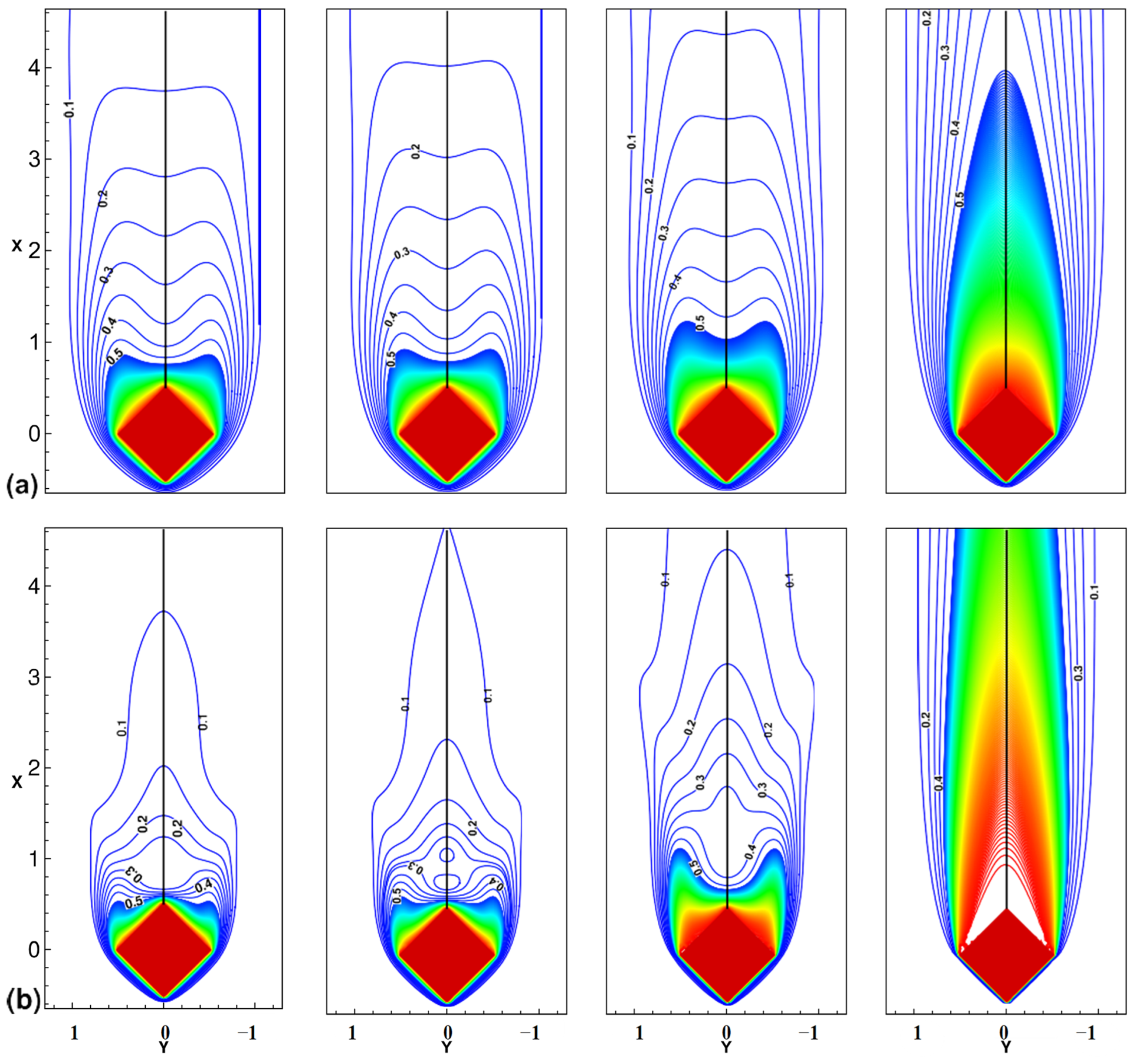
5.4.2. REV-LBM Simulation of Unsteady Flow and Heat Transfer around and through a Confined Diamond-Shaped Porous Block

Porous body arrangement could arise when designing porous heat sinks, pin-fin arrangements, etc. Recently, Vijaybabu et al. [167] have numerically investigated the hydrodynamic and thermal behavior of a diamond-shaped porous block confined in a laminar unsteady uniform flow via the SRT-LBM approach (see Figure 21). They demonstrated the effect of permeability on flow and heat transfer for different Darcy numbers ( 10 6 D a 10 2 ) and Reynolds numbers ( 50 Re 150 ). They pointed out that the higher the permeability, the greater the thermal plume downstream of the block.

6. Conclusions

Thermal energy storage in the form of sensible and latent heat continues to be a way to address the mismatch between energy supply and demand. It has been identified as a very attractive strategy for high energy efficiency buildings. This paper reviews advanced research studies regarding sensible and latent heat thermal energy storage in porous media. The open-ended straight channel incorporating a porous medium (copper foam) and paraffin (PCM) is the typical LHTES template. As metal foams and paraffin are the most widely used couple inPCMs and porous media, they are increasingly being used to improve heat transfer. The present review has focused on mesoscopic modeling approaches for single-phase and solid-liquid phase change heat transfer in porous media, which are widely involved in energy/environmental science and technology. This approach has experienced an amazing growth in the development of its methodologyand application over the past three decades showingdistinctive strengths over themacroscopic and microscopic numerical methods. Thereby, it bridged the gap between macroscopic methods dealing with Navier–Stokes equations and microscopic particle-based microscopic approaches such as the Monte Carlo and molecular dynamics methods.
A brief introduction to three methods that can handle the fluid flows and heat transfer involved in a typical chosen LHTES model has been provided. Subsequently, two simulation methods, i.e.,the REV-scale method and pore-scale method, have beenselected and compared, and it is concluded that the REV-scale simulation is able to provide the flow and heat transfer features without the tedious effort in implementing the pore-scale approach. The REV-scale modeling has been shown to provide a sufficiently accurate prediction of most transport mechanisms in porous media, and as such, it can help to achieve efficientdesign improvements of such systems. It should be stressed that for phase change heat transfer in porous media at the REV scale, the standard LB method must be modified to consider both the influence of the PCM and porous medium.
Based on the literature, the following conclusions can bedrawn:
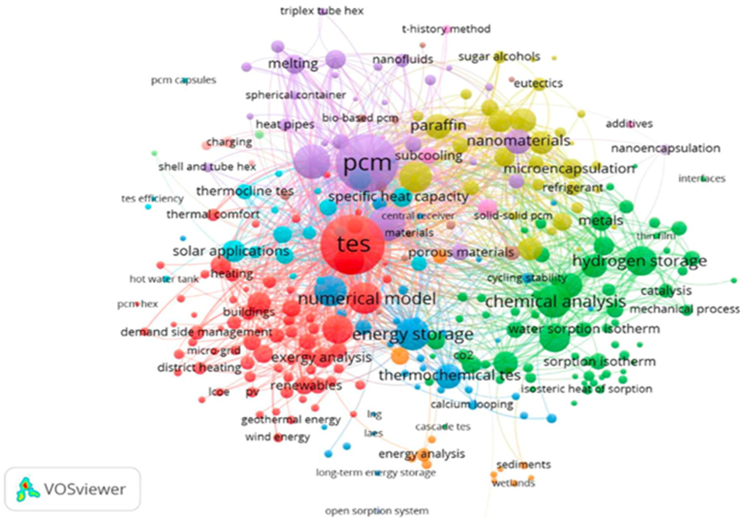
  • Through the bibliometric analysis that was carried out on TES methods, it is the LHS category that appeared to be the most relevant technique investigated.
  • SHS and LHS systems are most widely used systemsin different applications due to their high availability. However, most TCHS devices are not commercially available, except in a small range of applications, due to their unstable lifetime and high prices.
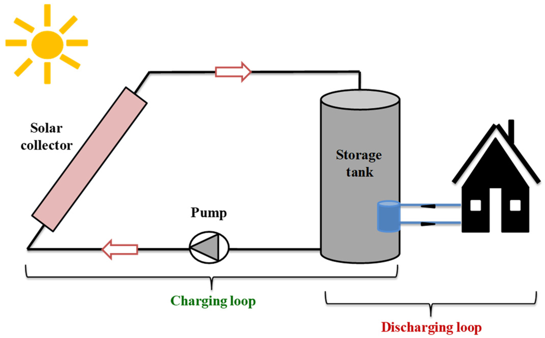
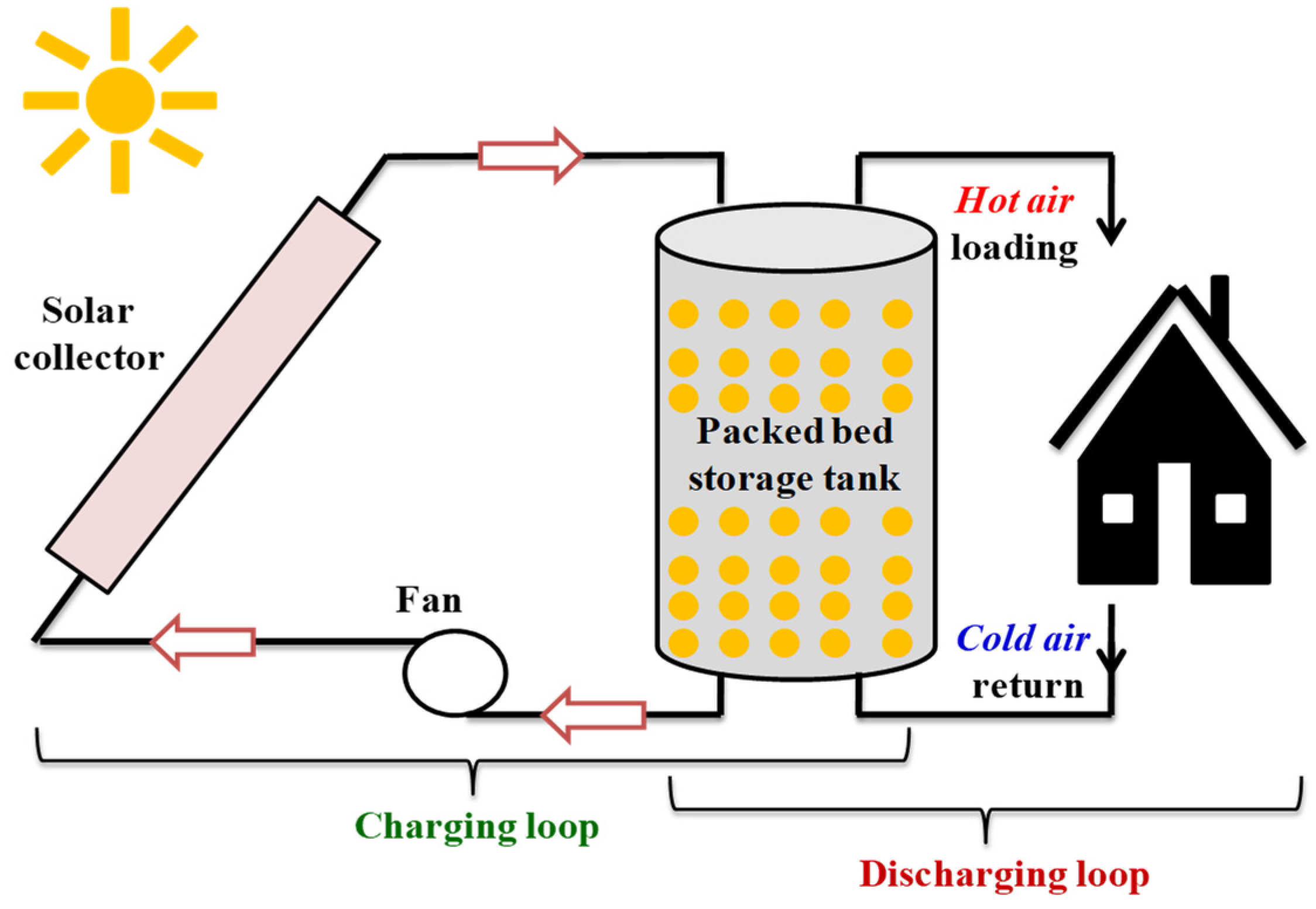
  • The SHS method has been widely used in solar applications where water is the most used material due to its low cost and high specific heat capacity. Note that porosity is one of the main parameters that influences the performance of any SHS system.
  • Despite their low thermal conductivity, PCMs can still be integrated into applications using various modes of incorporation, of which the impregnation of PCMs in porous structures appears to be the most relevant solution due to the high thermal conductivity engendered.
  • It turns out that PCMs can store an appreciable amount of energy which ismore than that ofSHSMs in a small relative storage volume.
  • Using foam metal in thermal energy storage can improve heat transfer rate while shortening charge/discharge periods.
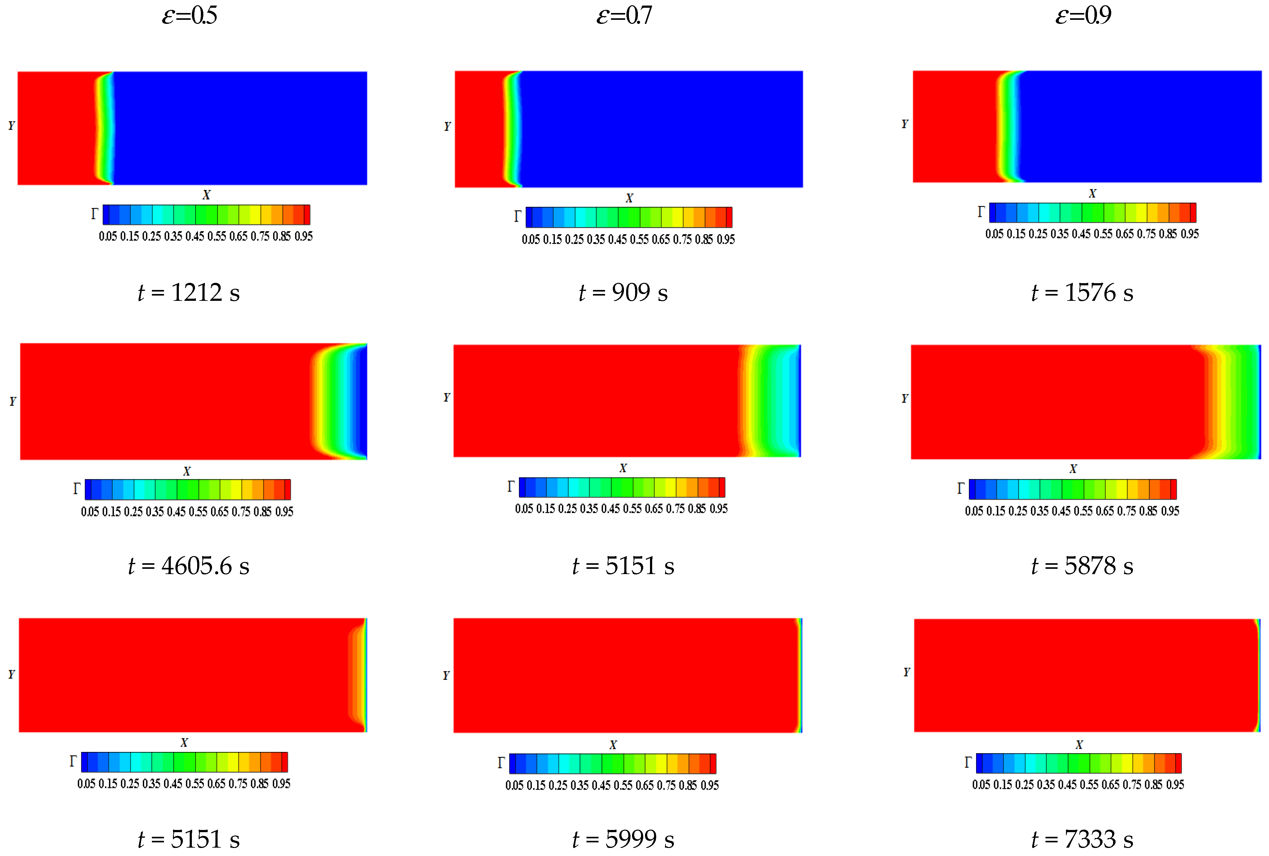
  • Decreasing the porosity speeds up the melting phenomenon
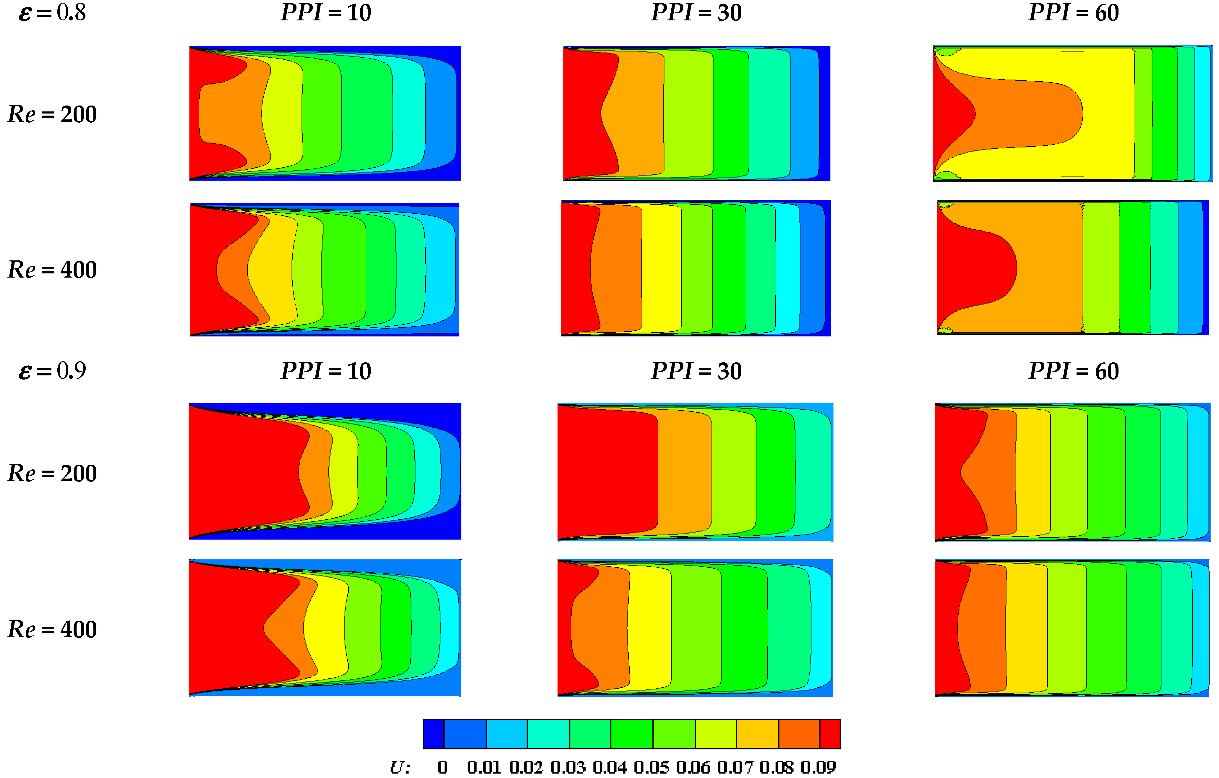
  • Increasing the PPI can enhance the forced convection heat transfer performance of the liquid PCM.
  • Pore-scale and REV-scale LBM approaches showed great potential for thesimulation of phase change phenomenon and sensible storage in a porous medium due to their inherent transienceand robustness to handle complexphysics. They can help to understand the complex interactions between different processes, which are challenging to obtain even for the most advanced experimental techniques. Their combinations with macro/micro/nano scale fabrication techniques will certainly lead to new generation porous media.
  • There is no doubt that LB methods will continue to play an increasingly important role in the study of solid-liquid phase change heat transfer in porous LHTES. However, this will certainly have to entail a development of a numerically stable and accurate multi-scale simulation method by combining the REV-scale and pore-scale methods.
To sum up, particular attention still needs to be paid to optimization works on the thermophysical, mechanical and geometric characteristics of PCMs and SHSMs. Two main research gaps have been identified. The first research gap is related to the weaknessof the environmental analysis, and the second is related to the weakness of technical–economic analysis. These two issues play a key role in the marketing of the devices studied and the optimization of their use. Moreover, the application of the LB method in micro/macro LHTES energy systems for more details analysis and optimization alsohasagreat potential.

Author Contributions

The authors have contributed to different parts of the paper preparation as follows: Conceptualization, R.M., H.N. and H.D.; Methodology, R.M., H.N., H.D. and A.C.B.; Software, R.M., H.D. and H.N.; Validation, R.M., H.N., H.D. and A.C.B.; Formal analysis, H.N., H.D. and A.C.B.; Investigation, R.M., H.N. and H.D.; Resources, R.M. and H.D.; Data curation, R.M. and H.D.; Writing—original draft, R.M., H.N., A.C.B. and H.D.; Writing—review and editing, H.N., H.D. and A.C.B.; Visualization, R.M., H.N. and H.D.; Supervision, H.N. and H.D.; Project administration, H.D.; Funding acquisition, H.D.The authors’ order was approved by mutual agreement between the authors. All authors have read and agreed to the published version of the manuscript.

Funding

This research has not received any specific grants from funding agencies in the public, commercial or non-profit sectors.

Acknowledgments

The authors very much appreciated the fruitful discussions taking place within the team which led to the elaboration of this work.

Conflicts of Interest

The authors declare no potential conflict of interest regarding authorship and/or publication of this paper. Furthermore, the first-author scholarship had no role in the study design nor in the manuscript writing or decision of its publication.

Nomenclature

a s f Specific interfacial area (m−1)
B i Biot number, B i = h s f a s f H 2 / λ s
cLattice speed ( m s 1 )
C p Specific heat capacity at constant pressure ( k J k g 1 K 1 )
c s Sound speed ( m s 1 )
D a Darcy number, D a = K H 2
dfMean ligament diameter (m)
dpMean pore diameter (m)
E c Eckert number, E c = U o 2 / ( C p f Δ T r e f )
e i Discrete velocity in direction i
F ε Forchheimer form coefficient
F Body force per unit mass ( N k g 1 )
F e i Discrete body force in direction i ( k g m 3 s 1 )
f i ,   g i Distribution function in direction i
gGravity
f i e q ,   g i e q Equilibrium distribution function in direction i
f i s Symmetric distribution function
f i a Antisymmetric distribution function
HCharacteristic length scale (m)
hEnthalpy
h s f Interfacial heat transfer coefficient ( W m 2 K 1 )
K Porous medium permeability (m2)
KnKnudsen number
K R Thermal conductivity ratio, K R = λ s / λ f
L a Latent heat ( J k g 1 )
M (N) Transformation relaxation matrix
m (n)Velocity moment
meq (neq)Equilibrium moment
p Pressure ( P a )
Pr Prandtl number, Pr = ν f / α f
RUniversal gas constant
RaRayleigh number
Re Reynolds number, Re = U i n H / ν f
Re d Pore Reynolds number, Re d = Re d p / ε H
R c Heat capacity ratio, R c = ( ρ C p ) s / ( ρ C p ) f
S i Source terms
Sf(Sg)Diagonal relaxation matrix
S t e Stefan number, S t e = C p f ( T h T m ) / L a
T Temperature ( K )
T m PCM melting temperature ( K )
Θ Dimensionless temperature
t Time (s)
u ,   v Velocity ( m s 1 )
U 0 Inlet velocity( m s 1 )
x ,   y Cartesian coordinates ( m )
Greek symbols
Gradient operator
. Divergence operator
α Thermal diffusivity ( m 2 s 1 )
β Thermal expansion coefficient ( K 1 )
ε Media porosity
ω Pore density (PPI)
λ Thermal conductivity ( W m 1 K 1 )
μ f Dynamic fluid viscosity ( kg m 1 s 1 )
Γ PCM melting fraction
ν Kinematic viscosity ( m 2 s 1 )
ρ Density ( kg m 3 )
τ a Free relaxation time
τ v / g , f / s Single relaxation time
τ i Relaxation rates
τ s Viscous relaxation time
Λ Monitor factor
Ω Collision operator
w i Weight coefficient in direction i
Superscripts/subscripts
e f f Effective
fFluid
i ¯ Direction opposite to i
mMelting
Initial state
RefReference
sSolid
Abbreviations
ARMAdaptive mesh refinement
BGKBhatnagar–Gross–Krook
CFDComputational fluid dynamics
CFLCourant–Friedrichs–Lewy
CNTCarbon nanotubes
DBTEDiscretization of Boltzmann transport equation
DSMCDirect simulation Monte Carlo
DNSDirect numerical simulation
DPDDissipative particle dissipation
EGExpanded graphite
ESEnergy storage
EUEuropean union
ESSEnergy storage system
FDMFinite difference method
FEMFinite element methods
FVMFinite volume methods
GKMGas-kinetic method
HPCHierarchical porous carbon
HPPHierarchical porouspolystyrene
HTFheat transfer fluid
IRENAInternational renewable energy agency
LESLarge eddy simulation
LBMLattice Boltzmann method
MDMolecular dynamics
MOFMetal organic framework
MRTMultiple relaxation time
NSCGNon-uniform staggered Cartesian grid
PCMPhase change material
PPIPore density (Pore Per Inch)
RANSReynolds-averaged Navier–Stokes
REVRepresentative elementary volume
TCHSThermochemical heat storage
TESThermal energy storage
TRTTwo relaxation time
LHTESLatent heat thermal energy storage
LHSLatent heat storage
PCPPorous coordination polymers
SHSSensible heat storage
SHSMSensible heat storage material
SRTSingle relaxation time
STESSeasonal thermal energy storage
ZEBZero energy buildings

References

  1. Xu, H.; Wang, N.; Zhang, C.; Qu, Z.; Cao, M. Optimization on the melting performance of triplex-layer PCMs in a horizontal finned shell and tube thermal energy storage unit. Appl. Therm. Eng. 2020, 176, 115409. [Google Scholar] [CrossRef]
  2. DeLong, J.P.; Burger, O. Socio-economic instability and the scaling of energy use with population size. PLoS ONE 2015, 10, e0130547. [Google Scholar] [CrossRef] [PubMed]
  3. Dincer, I.; Ezan, M.A. Heat Storage: A Unique Solution for Energy Systems; Springer: Cham, Switzerland, 2018. [Google Scholar]
  4. Sarbu, I.; Sebarchievici, C. Solar Heating and Cooling Systems: Fundamentals, Experimentsand Applications; Elsevier: Oxford, UK, 2016. [Google Scholar]
  5. Cabeza, L.F. Advances in Thermal Energy Storage Systems; Woodhead Publishing Series in Energy; Elsevier Science: Amsterdam, The Netherlands, 2015. [Google Scholar]
  6. Stutz, B.; Le Pierres, N.; Kuznik, F.; Johannes, K.; Del Barrio, E.P.; Bédécarrats, J.-P.; Gibout, S.; Marty, P.; Zalewski, L.; Soto, J.; et al. Storage of thermal solar energy. Comptes Rendus Phys. 2017, 18, 401–414. [Google Scholar] [CrossRef]
  7. Arce, P.; Medrano, M.; Gil, A.; Oró, E.; Cabeza, L.F. Overview of thermal energy storage (TES) potential energy savings and climate change mitigation in Spain and Europe. Appl. Energy 2011, 88, 2764–2774. [Google Scholar] [CrossRef]
  8. IRENA. Innovation Outlook: Thermal Energy Storage; International Renewable Energy Agency: Abu Dhabi, United Arab Emirates, 2020. [Google Scholar]
  9. Calderón, A.; Barreneche, C.; Hernández-Valle, K.; Galindo, E.; Segarra, M.; Fernández, A.I. Where is Thermal Energy Storage (TES) research going?—A bibliometric analysis. Sol. Energy 2020, 200, 37–50. [Google Scholar] [CrossRef]
  10. Ibrahim, H.; Ilinca, A.; Perron, J. Energy storage systems-Characteristics and comparisons. Renew. Sustain. Energy Rev. 2008, 12, 1221–1250. [Google Scholar] [CrossRef]
  11. Dahash, A.; Ochs, F.; Janetti, M.B.; Streicher, W. Advances in seasonal thermal energy storage for solar district heating applications: A critical review on large-scale hot-water tank and pit thermal energy storage systems. Appl. Energy 2019, 239, 296–315. [Google Scholar] [CrossRef]
  12. Guo, F.; Yang, X.; Xu, L.; Torrens, I.; Hensen, J. A central solar-industrial waste heat heating system with large scale borehole thermal storage. Procedia Eng. 2017, 205, 1584–1591. [Google Scholar] [CrossRef]
  13. Persson, J.; Westermark, M. Low-energy buildings and seasonal thermal energy storages from a behavioral economics perspective. Appl. Energy 2013, 112, 975–980. [Google Scholar] [CrossRef]
  14. Reed, A.L.; Novelli, A.P.; Doran, K.L.; Ge, S.; Lu, N.; McCartney, J.S. Solar district heating with underground thermal energy storage: Pathways to commercial viability in North America. Renew. Energy 2018, 126, 1–13. [Google Scholar] [CrossRef] [Green Version]
  15. International Renewable Energy Agency (IRENA). The Energy Technology Systems Analysis Program (ETSAP): Technology Brief E17; International Energy Agency (IEA): Paris, France, 2013; Available online: https://www.irena.org/-/media/Files/IRENA/Agency/Publication/2013/IRENA-ETSAP-Tech-Brief-E17-Thermal-Energy-Storage.pdf (accessed on 1 January 2013).
  16. Navarro, L.; de Gracia, A.; Niall, D.; Castell, A.; Browne, M.; McCormack, S.J.; Griffiths, P.; Cabeza, L.F. Thermal energy storage in building integrated thermal systems: A review. Part 2. Integration as passive system. Renew. Energy 2015, 85, 1334–1356. [Google Scholar] [CrossRef] [Green Version]
  17. Navarro, L.; De Gracia, A.; Niall, D.; Castell, A.; Browne, M.; Mccormack, S.J.; Griffiths, P.; Cabeza, L.F. Thermal energy storage in building integrated thermal systems: A review. Part 1. Active storage systems readable. Renew. Energy 2016, 88, 526–547. [Google Scholar] [CrossRef] [Green Version]
  18. Lizana, J.; Chacartegui, R.; Barrios-Padura, A.; Valverde, J.M. Advances in thermal energy storage materials and their applications towards zero energy buildings: A critical review. Appl. Energy 2017, 203, 219–239. [Google Scholar] [CrossRef]
  19. Romdhane, S.B.; Amamou, A.; Khalifa, R.B.; Said, N.M.; Younsi, Z.; Jemni, A. A review on thermal energy storage using phase change materials in passive building applications. J. Build. Eng. 2020, 32, 101563. [Google Scholar] [CrossRef]
  20. Rathore, P.K.S.; Shukla, S.K. Potential of macroencapsulated PCM for thermal energy storage in buildings: A comprehensive review. Constr. Build. Mater. 2019, 225, 723–744. [Google Scholar] [CrossRef]
  21. Hauer, A.; Bayern, Z. Storage Technology Issues and Opportunities. In Proceedings of the Strategic and Cross-Cutting Workshop “Energy Storage—Issues and Opportunities”, France, Paris, 15 February 2011. [Google Scholar]
  22. Borri, E.; Tafone, A.; Zsembinszki, G.; Comodi, G.; Romagnoli, A.; Cabeza, L.F. Recent trends on liquid air energy storage: A bibliometric analysis. Appl. Sci. 2020, 10, 2773. [Google Scholar] [CrossRef]
  23. Tarragona, J.; de Gracia, A.; Cabeza, L.F. Bibliometric analysis of smart control applications in thermal energy storage systems. A model predictive control approach. J. Energy Storage 2020, 32, 101704. [Google Scholar] [CrossRef]
  24. Cardenas-Ramírez, C.; Jaramillo, F.; Gomez, M. Systematic review of encapsulation and shape-stabilization of phase change materials. J. Energy Storage 2020, 30, 101495. [Google Scholar] [CrossRef]
  25. Mustapha, A.N.; Onyeaka, H.; Omoregbe, O.; Ding, Y.; Li, Y. Latent heat thermal energy storage: A bibliometric analysis explicating the paradigm from 2000–2019. J. Energy Storage 2020, 33, 102027. [Google Scholar] [CrossRef]
  26. Cabeza, L.F.; de Gracia, A.; Zsembinszki, G.; Borri, E. Perspectives on thermal energy storage research. Energy 2021, 231, 120943. [Google Scholar] [CrossRef]
  27. Zhao, Y.; Zhao, C.Y.; Markides, C.N.; Wang, H.; Li, W. Medium-and high-temperature latent and thermochemical heat storage using metals and metallic compounds as heat storage media: A technical review. Appl. Energy 2020, 280, 115950. [Google Scholar] [CrossRef]
  28. De Gracia, A.; Cabeza, L.F. Phase change materials and thermal energy storage for buildings. Energy Build. 2015, 103, 414–419. [Google Scholar] [CrossRef] [Green Version]
  29. Chandel, S.S.; Agarwal, T. Review of current state of research on energy storage, toxicity, health hazards and commercialization of phase changing materials. Renew. Sustain. Energy Rev. 2017, 67, 581–596. [Google Scholar] [CrossRef]
  30. Lin, Y.; Alva, G.; Fang, G. Review on thermal performances and applications of thermal energy storage systems with inorganic phase change materials. Energy 2018, 165, 685–708. [Google Scholar] [CrossRef]
  31. Fernández, A.; Martínez, M.; Segarra, M.; Martorell, I.; Cabeza, L.F. Selection of materials with potential in sensible thermal energy storage. Sol. Energy Mater. Sol. Cells 2010, 94, 1723–1729. [Google Scholar] [CrossRef]
  32. Kalaiselvam, S.; Parameshwaran, R. Thermal Energy Storage Technologies. In Thermal Energy Storage Technologies for Sustainability: Systems Design, Assessment, and Applications, 1st ed.; Academic Press: Cambridge, MA, USA, 2014; pp. 57–64. [Google Scholar] [CrossRef]
  33. Ståhl, F. Influence of Thermal Mass on the Heating and Cooling Demands of a Building Unit. Ph.D. Thesis, Chalmers University of Technology, Gothenburg, Sweden, 2009. [Google Scholar]
  34. Tatsidjodoung, P.; Le Pierrès, N.; Luo, L. A review of potential materials for thermal energy storage in building applications. Renew. Sustain. Energy Rev. 2013, 18, 327–349. [Google Scholar] [CrossRef]
  35. González-Roubaud, E.; Pérez-Osorio, D.; Prieto, C. Review of commercial thermal energy storage in concentrated solar power plants: Steam vs. molten salts. Renew. Sustain. Energy Rev. 2017, 80, 133–148. [Google Scholar] [CrossRef]
  36. Myers, P.D., Jr.; Goswami, D.Y. Thermal energy storage using chloride salts and their eutectics. Appl. Therm. Eng. 2016, 109, 889–900. [Google Scholar] [CrossRef] [Green Version]
  37. Elashmawy, M. Improving the performance of a parabolic concentrator solar tracking-tubular solar still (PCST-TSS) using gravel as a sensible heat storage material. Desalination 2020, 47, 114182. [Google Scholar] [CrossRef]
  38. Koçak, B.; Fernandez, A.I.; Paksoy, H. Review on sensible thermal energy storage for industrial solar applications and sustainability aspects. Sol. Energy 2020, 209, 135–169. [Google Scholar] [CrossRef]
  39. Ashby, M.F. Materials Selection in Mechanical Design, 3rd ed.; Elsevier: Oxford, UK, 2005. [Google Scholar]
  40. Ashby, M.F.; Shercliff, H.; Cebon, D. Materials Engineering, Science, Processing and Design, 4th ed.; Butterworth-Heinemann: Oxford, UK, 2007. [Google Scholar]
  41. Ayyappan, S.; Mayilsamy, K.; Sreenarayanan, V.V. Performance improvement studies in a solar greenhouse drier using sensible heat storage materials. Heat Mass Transf. 2016, 52, 459–467. [Google Scholar] [CrossRef]
  42. Klein, P.; Roos, T.H.; Sheer, T.J. Experimental investigation into a packed bed thermal storage solution for solar gas turbine systems. Energy Procedia 2014, 49, 840–849. [Google Scholar] [CrossRef] [Green Version]
  43. Almendros-Ibanez, J.A.; Fernandez-Torrijos, M.; Díaz-Heras, M.; Belmonte, J.F.; Sobrino, C.A. Review of solar thermal energy storage in beds of particles: Packed and fluidized beds. Sol. Energy 2018, 192, 193–237. [Google Scholar] [CrossRef]
  44. Elouali, A.; Kousksou, T.; El Rhafiki, T.; Hamdaoui, S.; Mahdaoui, M.; Allouhi, A.; Zeraouli, Y. Physical models for packed bed: Sensible heat storage systems. J. Energy Storage 2019, 23, 69–78. [Google Scholar] [CrossRef]
  45. Pelay, U.; Luo, L.; Fan, Y.; Stitou, D.; Rood, M. Thermal energy storage systems for concentrated solar power plants. Renew. Sustain. Energy Rev. 2017, 79, 82–100. [Google Scholar] [CrossRef]
  46. Kumar, A.; Kim, M.H. Solar air-heating system with packed-bed energy-storage systems. Renew. Sustain. Energy Rev. 2017, 72, 215–227. [Google Scholar] [CrossRef]
  47. Gil, A.; Medrano, M.; Martorell, I.; Lázaro, A.; Dolado, P.; Zalba, B.; Cabeza, L.F. State of the art on high temperature thermal energy storage for power generation. Part 1-Concepts, materials and modellization. Renew. Sustain. Energy Rev. 2010, 14, 31–55. [Google Scholar] [CrossRef]
  48. Mabrouk, R.; Naji, H.; Dhahri, H. Numerical Investigation of Metal Foam Pore Density Effect on Sensible and Latent Heats Storage through an Enthalpy-Based REV-Scale lattice Boltzmann Method. Processes 2021, 9, 1165. [Google Scholar] [CrossRef]
  49. Amami, B.; Rabhi, R.; Dhahri, H.; Mhimid, A. Numerical thermodynamic analysis of heat storage porous duct under pulsating flow using lattice Boltzmann method. Int. J. Exergy 2017, 22, 376–395. [Google Scholar] [CrossRef]
  50. Kasaeian, A.; Daneshazarian, R.; Mahian, O.; Kolsi, L.; Chamkha, A.J.; Wongwises, S.; Pop, I. Nanofluid flow and heat transfer in porous media: A review of the latest developments. Int. J. Heat Mass Transf. 2017, 107, 778–791. [Google Scholar] [CrossRef]
  51. Sheremet, M.A.; Pop, I. Natural convection in a horizontal cylindrical annulus filled with a porous medium saturated by a nanofluid using Tiwari and Das’ nanofluid model. Eur. Phys. J. Plus 2015, 130, 107. [Google Scholar] [CrossRef]
  52. Sheremet, M.A.; Grosan, T.; Pop, I. Free convection in a square cavity filled with a porous medium saturated by nanofluid using Tiwari and Das’ nanofluid model. Transp. Porous Media 2015, 106, 595–610. [Google Scholar] [CrossRef]
  53. Amami, B.; Dhahri, H.; Mhimid, A. Viscous dissipation effects on heat transfer, energy storage, and entropy generation for fluid flow in a porous channel submitted to a uniform magnetic field. J. Porous Media 2014, 17, 841–859. [Google Scholar] [CrossRef]
  54. Heap, M.J.; Xu, T.; Chen, C.F. The influence of porosity and vesicle size on the brittle strength of volcanic rocks and magma. Bull. Volcanol. 2014, 76, 859. [Google Scholar] [CrossRef]
  55. Dhifaoui, B.; Jabrallah, S.B.; Belghith, A.; Corriou, J.P. Experimental study of the dynamic behaviour of a porous medium submitted to a wall heat flux in view of thermal energy storage by sensible heat. Int. J. Therm. Sci. 2007, 46, 1056–1063. [Google Scholar] [CrossRef]
  56. Tian, Y.; Zhao, C.Y. A review of solar collectors and thermal energy storage in solar thermal applications. Appl. Energy 2013, 104, 538–553. [Google Scholar] [CrossRef] [Green Version]
  57. Mahlia, T.M.I.; Saktisahdan, T.J.; Jannifar, A.; Hasan, M.H.; Matseelar, H.S.C. A review of available methods and development on energy storage; technology update. Renew. Sustain. Energy Rev. 2014, 33, 532–545. [Google Scholar] [CrossRef]
  58. Reddy Prasad, D.M.; Senthilkumar, R.; Lakshmanarao, G.; Krishnan, S.; Naveen Prasad, B.S. A critical review on thermal energy storage materials and systems for solar applications. AimsEnergy 2019, 7, 507–526. [Google Scholar] [CrossRef]
  59. Saffari, M.; De Gracia, A.; Fernández, C.; Cabeza, L.F. Simulation-based optimization of PCM melting temperature to improve the energy performance in buildings. Appl. Energy 2017, 202, 420–434. [Google Scholar] [CrossRef] [Green Version]
  60. Sharma, A.; Tyagi, V.V.; Chen, C.R.; Buddhi, D. Review on thermal energy storage with phase change materials and applications. Renew. Sustain. Energy Rev. 2009, 13, 318–345. [Google Scholar] [CrossRef]
  61. Garg, H.P.; Mullick, S.C.; Bhargava, A.K. Solar Thermal Energy Storage; Reidel Publishing Company: Dordrecht, The Netherlands, 1985. [Google Scholar]
  62. Pillai, K.K.; Brinkwarth, B.J. The storage of low grade thermal energy using phase change materials. Appl. Energy 1976, 2, 205–216. [Google Scholar] [CrossRef]
  63. Alva, G.; Lin, Y.; Fang, G. An overview of thermal energy storage systems. Energy 2018, 144, 341–378. [Google Scholar] [CrossRef]
  64. Hasnain, S.M. Review on sustainable thermal energy storage technologies, Part I: Heat storage materials and techniques. Energy Convers. Manag. 1998, 39, 1127–1138. [Google Scholar] [CrossRef]
  65. Zhao, C.Y.; Lu, W.; Tian, Y. Heat transfer enhancement for thermal energy storage using metal foams embedded within phase change materials (PCMs). Sol. Energy 2010, 84, 1402–1412. [Google Scholar] [CrossRef] [Green Version]
  66. Dincer, I.; Rosen, M.A. Thermal Energy Storage Systems and Applications; John Wiley & Sons: Chichester, UK, 2002. [Google Scholar]
  67. Kimura, H.; Kai, J. Mixtures of calcium chloride hexahydrate with some salt hydrates or anhydrous salts as latent heat storage materials. Energy Convers. Manag. 1988, 28, 197–200. [Google Scholar] [CrossRef]
  68. Abhat, A. Low temperature latent heat thermal energy storage: Heat storage materials. Sol. Energy 1983, 30, 313–332. [Google Scholar] [CrossRef]
  69. Jegadheeswaran, S.; Pohekar, S.D. Performance enhancement in latent heat thermal storage system: A review. Renew. Sustain. Energy Rev. 2009, 13, 2225–2244. [Google Scholar] [CrossRef]
  70. Yehya, A.; Naji, H.; Zalewski, L. Experimental and numerical characterization of an impure phase change material using a thermal lattice Boltzmann method. Appl. Therm. Eng. 2019, 154, 738–750. [Google Scholar] [CrossRef]
  71. Kant, K.; Biwole, P.H.; Shamseddine, I.; Tlaiji, G.; Pennec, F.; Fardoun, F. Recent advances in thermophysical properties enhancement of phase change materials for thermal energy storage. Sol. Energy Mater. Sol. Cells 2021, 231, 111309. [Google Scholar] [CrossRef]
  72. Junaid, M.F.; Ur Rehman, Z.; Čekon, M.; Čurpek, J.; Farooq, R.; Cui, H.; Khan, I. Inorganic phase change materials in thermal energy storage: A review on perspectives and technological advances in building applications. Energy Build. 2021, 252, 111443. [Google Scholar] [CrossRef]
  73. Liu, Y.; Li, X.; Hu, P.; Hu, G. Study on the supercooling degree and nucleation behavior of water-based graphene oxide nanofluids PCM. Int. J. Refrig. 2015, 50, 80–86. [Google Scholar] [CrossRef]
  74. Nomura, T.; Okinaka, N.; Akiyama, T. Technology of latent heat storage for high temperature application: A review. ISIJ Int. 2010, 50, 1229–1239. [Google Scholar] [CrossRef] [Green Version]
  75. Khadiran, T.; Hussein, M.Z.; Zainal, Z.; Rusli, R. Advanced energy storage materials for building applications and their thermal performance characterization: A review. Renew. Sustain. Energy Rev. 2016, 57, 916–928. [Google Scholar] [CrossRef]
  76. Memon, S.A. Phase change materials integrated in building walls: A state of the art review. Renew. Sustain. Energy Rev. 2014, 31, 870–906. [Google Scholar] [CrossRef]
  77. Zhou, D.; Zhao, C.Y.; Tian, Y. Review on thermal energy storage with phase change materials (PCMs) in building applications. Appl. Energy 2012, 92, 593–605. [Google Scholar] [CrossRef] [Green Version]
  78. Wang, X.; Li, W.; Luo, Z.; Wang, K.; Shah, S.P. A critical review on phase change materials (PCM) for sustainable and energy efficient building: Design, characteristic, performance and application. Energy Build. 2022, 260, 111923. [Google Scholar] [CrossRef]
  79. Wuttig, M.; Yamada, N. Phase-change materials for rewriteable data storage. Nat. Mater. 2007, 6, 824–832. [Google Scholar] [CrossRef]
  80. Zhang, W.; Mazzarello, R.; Wuttig, M.; Ma, E. Designing crystallization in phase change materials for universal memory and neuro-inspired computing. Nat. Rev. Mater. 2019, 4, 150–168. [Google Scholar] [CrossRef]
  81. Yancheshme, A.A.; Allahdini, A.; Maghsoudi, K.; Jafari, R.; Momen, G. Potential anti-icing applications of encapsulated phase change material-embedded coatings; a review. J. Energy Storage 2020, 31, 101638. [Google Scholar] [CrossRef]
  82. Rostami, S.; Afrand, M.; Shahsavar, A.; Sheikholeslami, M.; Kalbasi, R.; Aghakhani, S.; Shadlo, M.S.; Oztop, H.F. A review of melting and freezing processes of PCM/nano-PCM and their application in energy storage. Energy 2020, 211, 118698. [Google Scholar] [CrossRef]
  83. Dieckmann, J. Latent Heat Storage in Concrete; University of Kai Serslautern: Kaiserslautern, Germany, 2006. [Google Scholar]
  84. Sarbu, I.; Dorca, A. Review on heat transfer analysis in thermal energy storage using latent heat storage systems and phase change materials. Int. J. Energy Res. 2019, 43, 29–64. [Google Scholar] [CrossRef] [Green Version]
  85. Faraj, K.; Khaled, M.; Faraj, J.; Hachem, F.; Castelain, C. Phase change material thermal energy storage systems for cooling applications in buildings: A review. Renew. Sustain. Energy Rev. 2020, 119, 109579. [Google Scholar] [CrossRef]
  86. Akeiber, H.; Nejat, P.; Majid, M.Z.A.; Wahid, M.A.; Jomehzadeh, F.; Famileh, I.Z.; Calautit, J.K.; Hughes, B.R.; Zaki, S.A. A review on phase change material (PCM) for sustainable passive cooling in building envelopes. Renew. Sustain. Energy Rev. 2016, 60, 1470–1497. [Google Scholar] [CrossRef]
  87. Cabeza, L.F.; Castell, A.; Barreneche, C.D.; De Gracia, A.; Fernández, A.I. Materials used as PCM in thermal energy storage in buildings: A review. Renew. Sustain. Energy Rev. 2011, 15, 1675–1695. [Google Scholar] [CrossRef]
  88. Battisti, A.; Persiani, S.G.; Crespi, M. Review and mapping of parameters for the early stage design of adaptive building technologies through life cycle assessment tools. Energies 2019, 12, 1729. [Google Scholar] [CrossRef] [Green Version]
  89. Fabiani, C.; Pisello, A.L.; Barbanera, M.; Cabeza, L.F.; Cotana, F. Assessing the potentiality of animal fat based-bio phase change materials (PCM) for building applications: An innovative multipurpose thermal investigation. Energies 2019, 12, 1111. [Google Scholar] [CrossRef] [Green Version]
  90. Alam, M.; Zou, P.X.; Sanjayan, J.; Ramakrishnan, S. Energy saving performance assessment and lessons learned from the operation of an active phase change materials system in a multi-storey building in Melbourne. Appl. Energy 2019, 238, 1582–1595. [Google Scholar] [CrossRef]
  91. Arivazhagan, R.; Geetha, N.B.; Sivasamy, P.; Kumaran, P.; Gnanamithra, M.K.; Sankar, S.; Loganathan, G.B.; Arivarasan, A. Review on performance assessment of phase change materials in buildings for thermal management through passive approach. Mater. Today Proc. 2020, 22, 419–431. [Google Scholar] [CrossRef]
  92. Souayfane, F.; Fardoun, F.; Biwole, P.H. Phase change materials (PCM) for cooling applications in buildings: A review. Energy Build. 2016, 129, 396–431. [Google Scholar] [CrossRef]
  93. Umair, M.M.; Zhang, Y.; Iqbal, K.; Zhang, S.; Tang, B. Novel strategies and supporting materials applied to shape-stabilize organic phase change materials for thermal energy storage-A review. Appl. Energy 2019, 235, 846–873. [Google Scholar] [CrossRef]
  94. Kenisarin, M.M. Thermophysical properties of some organic phase change materials for latent heat storage. A review. Sol. Energy 2014, 107, 553–575. [Google Scholar] [CrossRef]
  95. Zhang, N.; Yuan, Y.; Cao, X.; Du, Y.; Zhang, Z.; Gui, Y. Latent heat thermal energy storage systems with solid–liquid phase change materials: A review. Adv. Eng. Mater. 2018, 20, 1700753. [Google Scholar] [CrossRef]
  96. Ferrer, G.; Solé, A.; Barreneche, C.; Martorell, I.; Cabeza, L.F. Review on the methodology used in thermal stability characterization of phase change materials. Renew. Sustain. Energy Rev. 2015, 50, 665–685. [Google Scholar] [CrossRef] [Green Version]
  97. Khudhair, A.M.; Farid, M.M. A review on energy conservation in building applications with thermal storage by latent heat using phase change materials. Energy Convers. Manag. 2004, 45, 263–275. [Google Scholar] [CrossRef]
  98. Shchukina, E.M.; Graham, M.; Zheng, Z.; Shchukin, D.G. Nanoencapsulation of phase change materials for advanced thermal energy storage systems. Chem. Soc. Rev. 2018, 47, 4156–4175. [Google Scholar] [CrossRef] [Green Version]
  99. Al Shannaq, R.; Farid, M.M. Microencapsulation of phase change materials (PCMs) for thermal energy storage systems. In Advances in Thermal Energy Storage Systems; Woodhead Publishing: Sawston, UK, 2015; pp. 247–284. [Google Scholar] [CrossRef]
  100. Liu, C.; Rao, Z.; Zhao, J.; Huo, Y.; Li, Y. Review on nano-encapsulated phase change materials: Preparation, characterization and heat transfer enhancement. Nano Energy 2015, 13, 814–826. [Google Scholar] [CrossRef]
  101. Liu, L.; Alva, G.; Huang, X.; Fang, G. Preparation, heat transfer and flow properties of microencapsulated phase change materials for thermal energy storage. Renew. Sustain. Energy Rev. 2016, 66, 399–414. [Google Scholar] [CrossRef]
  102. Weaver, J.A.; Viskanta, R. Freezing of water saturated porous media in a rectangular cavity. Int. Commun. Heat Mass Transf. 1986, 13, 245–252. [Google Scholar] [CrossRef]
  103. Wang, Z.; Situ, W.; Li, X.; Zhang, G.; Huang, Z.; Yuan, W.; Yang, C.; Yang, C. Novel shape stabilized phase change material based on epoxy matrix with ultrahigh cycle life for thermal energy storage. Appl. Therm. Eng. 2017, 123, 1006–1012. [Google Scholar] [CrossRef]
  104. Xiao, X.; Zhang, P.; Li, M. Preparation and thermal characterization of paraffin/metal foam composite phase change material. Appl. Energy 2013, 112, 1357–1366. [Google Scholar] [CrossRef]
  105. Huang, X.; Chen, X.; Li, A.; Atinafu, D.; Gao, H.; Dong, W.; Wang, G. Shape-stabilized phase change materials based on porous supports for thermal energy storage applications. Chem. Eng. J. 2019, 356, 641–661. [Google Scholar] [CrossRef]
  106. Zhang, H.L.; Baeyens, J.; Degrève, J.; Cáceres, G.; Segal, R.; Pitié, F. Latent heat storage with tubular-encapsulated phase change materials (PCMs). Energy 2014, 76, 66–72. [Google Scholar] [CrossRef] [Green Version]
  107. Ling, Z.; Zhang, Z.; Shi, G.; Fang, X.; Wang, L.; Gao, X.; Fang, Y.; Xu, T.; Wang, S.; Liu, X. Review on thermal management systems using phase change materials for electronic components, Li-ion batteries and photovoltaic modules. Renew. Sustain. Energy Rev. 2014, 31, 427–438. [Google Scholar] [CrossRef] [Green Version]
  108. Bianco, N.; Busiello, S.; Iasiello, M.; Mauro, G.M. Finned heat sinks with phase change materials and metal foams: Pareto optimization to address cost and operation time. Appl. Therm. Eng. 2021, 197, 117436. [Google Scholar] [CrossRef]
  109. Khodadadi, J.M.; Fan, L.; Babaei, H. Thermal conductivity enhancement of nanostructure-based colloidal suspensions utilized as phase change materials for thermal energy storage: A review. Renew. Sustain. Energy Rev. 2013, 24, 418–444. [Google Scholar] [CrossRef]
  110. Sarkar, J.; Ghosh, P.; Adil, A. A review on hybrid nanofluids: Recent research, development and applications. Renew. Sustain. Energy Rev. 2015, 43, 164–177. [Google Scholar] [CrossRef]
  111. Şahan, N.; Fois, M.; Paksoy, H. Improving thermal conductivity phase change materials—A study of paraffin nanomagnetite composites. Sol. Energy Mater. Sol. Cells 2015, 137, 61–67. [Google Scholar] [CrossRef]
  112. Zhai, X.Q.; Wang, X.L.; Wang, T.; Wang, R.Z. A review on phase change cold storage in air-conditioning system: Materials and applications. Renew. Sustain. Energy Rev. 2013, 22, 108–120. [Google Scholar] [CrossRef]
  113. Feng, D.; Feng, Y.; Qiu, L.; Li, P.; Zang, Y.; Zou, H.; Yu, Z.; Zhang, X. Review on nano-porous composite phase change materials: Fabrication, characterization, enhancement and molecular simulation. Renew. Sustain. Energy Rev. 2019, 109, 578–605. [Google Scholar] [CrossRef]
  114. Zhang, S.; Feng, D.; Shi, L.; Wang, L.; Jin, Y.; Tian, L.; Yan, Y. A review of phase change heat transfer in shape-stabilized phase change materials (ss-PCMs) based on porous supports for thermal energy storage. Renew. Sustain. Energy Rev. 2021, 135, 110127. [Google Scholar] [CrossRef]
  115. Gao, H.; Wang, J.; Chen, X.; Wang, G.; Huang, X.; Li, A.; Dong, W. Nanoconfinement effects on thermal properties of nanoporous shape-stabilized composite PCMs: A review. Nano Energy 2018, 53, 769–797. [Google Scholar] [CrossRef]
  116. Mesalhy, O.; Lafdi, K.; Elgafy, A.; Bowman, K. Numerical study for enhancing the thermal conductivity of phase change material (PCM) storage using high thermal conductivity porous matrix. Energy Convers. Manag. 2005, 46, 847–867. [Google Scholar] [CrossRef]
  117. Alva, G.; Liu, L.; Huang, X.; Fang, G. Thermal energy storage materials and systems for solar energy applications. Renew. Sustain. Energy Rev. 2017, 68, 693–706. [Google Scholar] [CrossRef]
  118. Mabrouk, R.; Naji, H.; Dhahri, H.; Hammouda, S.; Younsi, Z. Numerical investigation of porosity effect on a PCM’s thermal performance in a porous rectangular channel via thermal lattice Boltzmann method. Int. Commun. Heat Mass Transf. 2020, 119, 104992. [Google Scholar] [CrossRef]
  119. Mabrouk, R.; Naji, H.; Dhahri, H.; Younsi, Z. Insight into Foam Pore Effect on Phase Change Process in a Plane Channel under Forced Convection Using the Thermal Lattice Boltzmann Method. Energies 2020, 13, 3979. [Google Scholar] [CrossRef]
  120. Yang, X.; Wei, P.; Wang, X.; He, Y.L. Gradient design of pore parameters on the melting process in a thermal energy storage unit filled with open-cell metal foam. Appl. Energy 2020, 268, 115019. [Google Scholar] [CrossRef]
  121. Li, Z.; Shahsavar, A.; Al-Rashed, A.A.; Talebizadehsardari, P. Effect of porous medium and nanoparticles presences in a counter-current triple-tube composite porous/nano-PCM system. Appl. Therm. Eng. 2020, 167, 114777. [Google Scholar] [CrossRef]
  122. Sardari, P.T.; Mohammed, H.I.; Giddings, D.; Gillott, M.; Grant, D. Numerical study of a multiple-segment metal foam-PCM latent heat storage unit: Effect of porosity, pore density and location of heat source. Energy 2019, 189, 116108. [Google Scholar] [CrossRef]
  123. Yang, X.; Bai, Q.; Zhang, Q.; Hu, W.; Jin, L.; Yan, J. Thermal and economic analysis of charging and discharging characteristics of composite phase change materials for cold storage. Appl. Energy 2018, 225, 585–599. [Google Scholar] [CrossRef]
  124. Zhang, P.; Meng, Z.N.; Zhu, H.; Wang, Y.L.; Peng, S.P. Melting heat transfer characteristics of a composite phase change material fabricated by paraffin and metal foam. Appl. Energy 2017, 185, 1971–1983. [Google Scholar] [CrossRef] [Green Version]
  125. Atal, A.; Wang, Y.; Harsha, M.; Sengupta, S. Effect of porosity of conducting matrix on a phase change energy storage device. Int. J. Heat Mass Transf. 2016, 93, 9–16. [Google Scholar] [CrossRef]
  126. Mallow, A.; Abdelaziz, O.; Graham, S. Thermal charging performance of enhanced phase change material composites for thermal battery design. Int. J. Therm. Sci. 2018, 127, 19–28. [Google Scholar] [CrossRef]
  127. Li, W.Q.; Qu, Z.G.; He, Y.L.; Tao, W.Q. Experimental and numerical studies on melting phase change heat transfer in open-cell metallic foams filled with paraffin. Appl. Therm. Eng. 2012, 37, 1–9. [Google Scholar] [CrossRef]
  128. Allen, M.J.; Bergman, T.L.; Faghri, A.; Sharifi, N. Robust heat transfer enhancement during melting and solidification of a phase change material using a combined heat pipe-metal foam or foil configuration. J. Heat Transf. 2015, 137, 102301. [Google Scholar] [CrossRef]
  129. Devaux, P.; Farid, M.M. Benefits of PCM underfloor heating with PCM wallboards for space heating in winter. Appl. Energy 2017, 191, 593–602. [Google Scholar] [CrossRef]
  130. Luo, K.H.; Xia, J.; Monaco, E. Multiscale modeling of multiphase flow with complex interactions. J. Mult. Model. 2009, 1, 125–156. [Google Scholar] [CrossRef]
  131. Succi, S. The Lattice Boltzmann Equation for Fluid Dynamics and Beyond; Oxford University Press: Oxford, UK, 2001. [Google Scholar]
  132. Chen, S.; Doolen, G.D. Lattice Boltzmann method for fluid flows. Ann. Rev. Fluid Mech. 1998, 30, 329–364. [Google Scholar] [CrossRef] [Green Version]
  133. Yoshino, M.; Matsuda, Y.; Shao, C. Comparison of accuracy and efficiency between the lattice Boltzmann method and the finite difference method in viscous/thermal fluid flows. Int. J. Comput. Fluid Dyn. 2004, 18, 333–345. [Google Scholar] [CrossRef]
  134. Mishra, S.C.; Lankadasu, A. Transient conduction-radiation heat transfer in participating media using the lattice Boltzmann method and the discrete transfer method. Numer. Heat Transf. Part A Appl. 2005, 47, 935–954. [Google Scholar] [CrossRef]
  135. Mondal, B.; Mishra, S.C. Application of the lattice Boltzmann method and the discrete ordinates method for solving transient conduction and radiation heat transfer problems. Numer. Heat Transf. Part A Appl. 2007, 52, 757–775. [Google Scholar] [CrossRef]
  136. Gohari, S.M.I.; Ghadyani, M. Effects of GPU structuring on accelerated schemes of LBM and classical CFD for flow over a flat plate. J. Math. Sys. Sci. 2012, 2, 126–132. [Google Scholar]
  137. Goodarzi, M.; Safaei, M.R.; Karimipour, A.; Hooman, K.; Dahari, M.; Kazi, S.N.; Sadeghinezhad, E. Comparison of the finite volume and lattice Boltzmann methods for solving natural convection heat transfer problems inside cavities and enclosures. Abstr. Appl. Anal. 2014, 2014, 762184. [Google Scholar] [CrossRef]
  138. Kerimo, J.; Girimaji, S.S. Boltzmann-BGK approach to simulating weakly compressible 3D turbulence: Comparison between lattice Boltzmann and gas kinetic methods. J. Turbul. 2009, 8, N46. [Google Scholar] [CrossRef]
  139. Sharma, K.V.; Straka, R.; Tavares, F.W. Lattice Boltzmann methods for industrial applications. Ind. Eng. Chem. Res. 2019, 58, 16205–16234. [Google Scholar] [CrossRef]
  140. Fakhari, A.; Lee, T. Finite-difference lattice Boltzmann method with a block-structured adaptive-mesh-refinement technique. Phys. Rev. E 2014, 89, 033310. [Google Scholar] [CrossRef]
  141. Schönherr, M.; Kucher, K.; Geier, M.; Stiebler, M.; Freudiger, S.; Krafczyk, M. Multi-thread implementations of the lattice Boltzmann method on non-uniform grids for CPUs and GPUs. Comput. Math. Appl. 2011, 61, 3730–3743. [Google Scholar] [CrossRef] [Green Version]
  142. Lagrava, D.; Malaspinas, O.; Latt, J.; Chopard, B. Advances in multi-domain lattice Boltzmann grid refinement. J. Comput. Phys. 2012, 231, 4808–4822. [Google Scholar] [CrossRef] [Green Version]
  143. Valero-Lara, P.; Jansson, J. A non-uniform Staggered Cartesian grid approach for Lattice-Boltzmann method. Procedia Comput. Sci. 2015, 51, 296–305. [Google Scholar] [CrossRef] [Green Version]
  144. He, X.; Luo, L.S.; Dembo, M. Some progress in lattice Boltzmann method. Part I. Nonuniform mesh grids. J. Comput. Phys. 1996, 129, 357–363. [Google Scholar] [CrossRef] [Green Version]
  145. Luo, L.S.; Liao, W.; Chen, X.; Peng, Y.; Zhang, W. Numerics of the lattice Boltzmann method: Effects of collision models on the lattice Boltzmann simulations. Phys. Rev. E 2011, 83, 056710. [Google Scholar] [CrossRef] [Green Version]
  146. Le, G.; Zhang, J. Boundary slip from the immersed boundarylattice Boltzmann models. Phys. Rev. E 2009, 79, 026701. [Google Scholar] [CrossRef] [PubMed]
  147. d’Humières, D. Multiple-relaxation-time lattice Boltzmann models in three dimensions. Philos. Trans. R. Soc. A 2002, 360, 437–451. [Google Scholar] [CrossRef] [PubMed]
  148. Yan, Z.; Hilpert, M. A multiple-relaxation-time lattice-Boltzmannmodel for bacterial chemotaxis: Effects of initial concentration, diffusion, and hydrodynamic dispersion on traveling bacterial bands. Bull. Math. Biol. 2014, 76, 2449–2475. [Google Scholar] [CrossRef]
  149. Ginzburg, I. Equilibrium-type and link-type lattice Boltzmann models for generic advection and anisotropic-dispersion equation. Adv. Water Resour. 2005, 28, 1171–1195. [Google Scholar] [CrossRef]
  150. Ginzburg, I. Generic boundary conditions for lattice Boltzmann models and their application to advection and anisotropic dispersion equations. Adv. Water Resour. 2005, 28, 1196–1216. [Google Scholar] [CrossRef]
  151. Bhatnagar, P.L.; Gross, E.P.; Krook, M. A model for collision processes in gases. I. Small amplitude processes in charged and neutral one-component systems. Phys. Rev. 1954, 94, 511. [Google Scholar] [CrossRef]
  152. Guo, Z.; Zhao, T.S. Lattice Boltzmann model for incompressible flows through porous media. Phys. Rev. E 2002, 66, 036304. [Google Scholar] [CrossRef]
  153. Mezrhab, A.; Moussaoui, M.A.; Jami, M.; Naji, H.; Bouzidi, M.H. Double MRT thermal lattice Boltzmann method for simulating convective flows. Phys. Lett. A 2010, 374, 3499–3507. [Google Scholar] [CrossRef]
  154. Ginzburg, I. Lattice Boltzmann modeling with discontinuous collision components: Hydrodynamic and advection-diffusion equations. J. Stat. Phys. 2007, 126, 157–206. [Google Scholar] [CrossRef]
  155. Ginzburg, I. Consistent Lattice Boltzmann schemes for the Brinkman model of porous flow and infinite Chapman-Enskog expansion. Phys. Rev. E 2008, 77, 066704. [Google Scholar] [CrossRef]
  156. Ginzburg, I.; Verhaeghe, F.; d’Humieres, D. Two-relaxation-time lattice Boltzmann scheme: About parametrization, velocity, pressure and mixed boundary conditions. Commun. Comput. Phys. 2008, 3, 427–478. [Google Scholar]
  157. Ma, Q.; Chen, Z.; Liu, H. Multiple-relaxation-time lattice Boltzmann simulation for flow, mass transfer, and adsorption in porous media. Phys. Rev. E 2017, 96, 013313. [Google Scholar] [CrossRef] [PubMed] [Green Version]
  158. Li, Q.; Luo, K.H.; Kang, Q.J.; He, Y.L.; Chen, Q.; Liu, Q. Lattice Boltzmann methods for multiphase flow and phase-change heat transfer. Prog. Energy Combust. Sci. 2016, 52, 62–105. [Google Scholar] [CrossRef] [Green Version]
  159. Gao, D.; Chen, Z. Lattice Boltzmann simulation of natural convection dominated melting in a rectangular cavity filled with porous media. Int. J. Therm. Sci. 2011, 50, 493–501. [Google Scholar] [CrossRef]
  160. Yang, X.; Bai, Q.; Guo, Z.; Niu, Z.; Yang, C.; Jin, L.; Lu, T.J.; Yan, J. Comparison of direct numerical simulation with volume-averaged method on composite phase change materials for thermal energy storage. Appl. Energy 2018, 229, 700–714. [Google Scholar] [CrossRef]
  161. Li, X.; Zhu, Z.; Xu, Z.; Ma, T.; Zhang, H.; Liu, J.; Wang, Q.; Wang, Q. A three-dimensional pore-scale lattice Boltzmann model for investigating the supergravity effects on charging process. Appl. Energy 2019, 254, 113507. [Google Scholar] [CrossRef]
  162. Ren, Q.; He, Y.-L.; Su, K.-Z.; Chan, C.L. Investigation of the effect of metal foam characteristics on the PCM melting performance in a latent heat thermal energy storage unit by pore-scale lattice Boltzmann modeling. Numer. Heat Transf. A-Appl. 2017, 72, 745–764. [Google Scholar] [CrossRef]
  163. Li, X.; Ma, T.; Liu, J.; Zhang, H.; Wang, Q. Pore-scale investigation of gravity effects on phase change heat transfer characteristics using lattice Boltzmann method. Appl. Energy 2018, 222, 92–103. [Google Scholar] [CrossRef]
  164. Andreozzi, A.; Iasiello, M.; Tucci, C. Numerical Investigation of a Phase Change Material Including Natural Convection Effects. Energies 2021, 14, 348. [Google Scholar] [CrossRef]
  165. Feng, S.; Shi, M.; Li, Y.; Lu, T.J. Pore-scale and volume-averaged numerical simulations of melting phase change heat transfer in finned metal foam. Int. J. Heat Mass Transf. 2015, 90, 838–847. [Google Scholar] [CrossRef]
  166. Mabrouk, R.; Dhahri, H.; Naji, H.; Hammouda, S.; Younsi, Z. Lattice Boltzmann simulation of forced convection melting of a composite phase change material with heat dissipation through an open-ended channel. Int. J. Heat Mass Transf. 2020, 153, 119606. [Google Scholar] [CrossRef]
  167. Vijaybabu, T.R.; Anirudh, K.; Dhinakaran, S. LBM simulation of unsteady flow and heat transfer from a diamond-shaped porous cylinder. Int. J. Heat Mass Transf. 2018, 120, 267–283. [Google Scholar] [CrossRef]
Figure 1. Energy use (W) vs. population size in the world and in selected countries [2].
Applsci 12 06995 g001
Figure 2. Yearly CO2 emissions from diverse sectors of energy by 2050 [8].
Applsci 12 06995 g002
Figure 3. Keywords’ co-occurrence for the storage sector [26], reprinted/adapted with permission from Ref. [26], 2022, Elsevier.
Applsci 12 06995 g003
Figure 4. SHS typical diagram during sensible heating or cooling with no phase transition.
Applsci 12 06995 g004
Figure 5. Simple solar application: solar-based water heating device, reprinted/adapted with permission from Ref. [3], 2022, Springer Nature.
Applsci 12 06995 g005
Figure 6. Most available and common SHSMs, reprinted/adapted with permission from Ref. [18], 2022, Elsevier.
Applsci 12 06995 g006
Figure 7. Heating application: porous packed bed SHS system, reprinted/adapted with permission from Ref. [3], 2022, Springer Nature.
Applsci 12 06995 g007
Figure 8. Diagram of enthalpy–temperature change during latent heat storage, reprinted/adapted with permission from Refs. [3,28], 2022, Springer Nature and Elsevier.
Applsci 12 06995 g008
Figure 9. The supercooling phenomenon, reprinted/adapted with permission from Ref. [72], 2022, Elsevier.
Applsci 12 06995 g009
Figure 10. Phase segregation [3]., reprinted/adapted with permission from Ref. [3], 2022, Springer Nature.
Applsci 12 06995 g010
Figure 11. PCMs’ subdivision based on phase transition [3,20,24,75,76,77], reprinted/adapted with permission from Refs. [20,24,75], 2022, Elsevier.
Applsci 12 06995 g011
Figure 12. Melting enthalpy vs. melting temperature for some PCMs [77,78,82,83,84], reprinted/adapted with permission from Ref. [82], 2022, Elsevier.
Applsci 12 06995 g012
Figure 13. Influence of PCMs on performance of LHS system, reprinted/adapted with permission from Ref. [3], 2022, Springer Nature.
Applsci 12 06995 g013
Figure 14. PCMs incorporation techniques [20,103,104,105], reprinted/adapted with permission from Refs. [20,103], 2022, Elsevier.
Applsci 12 06995 g014
Figure 15. Porous support materials [114,115], reprinted/adapted with permission from Ref. [114], 2022, Elsevier.
Applsci 12 06995 g015
Figure 16. Hierarchy scale of modeling and simulation methods ranging from Euler to molecular dynamics, reprinted/adapted with permission from Ref. [130], 2022, World Scientific.
Applsci 12 06995 g016
Figure 17. LBM general flowchart.
Applsci 12 06995 g017
Figure 18. Reynolds number effect on temperature contours ( Θ f ,   Θ s ) during the charging process with Pr = 50 ,   K r = 10 3 ,   R c = 1 ,   B i = 0.1 ,   D a = 10 3 ,   E c = 0 and ε = 0.6 [166]: (a) Re = 400; (b) Re = 600, reprinted/adapted with permission from Ref. [166], 2022, Elsevier.
Applsci 12 06995 g018
Figure 19. Porosity effects on melt front ( Γ ) vs. time during charging process for Re = 400 with Pr = 50 ,   B i = 0.1 ,   S t e = 1 ,   D a = 10 3 ,   K r = 1000 ,   R c = 1 ,   E c = 5 [118].
Applsci 12 06995 g019
Figure 20. Pore density effect on U-contours during charging process at ε = 0.8 and 0.9 [119].
Applsci 12 06995 g020
Figure 21. Time-averaged isotherm contours of mean flow around and through a permeable diamond-shaped cylinder at: (a) Re = 50 and (b) Re = 150 for various Darcy numbers [167], reprinted/adapted with permission from Ref. [167], 2022, Elsevier.
Applsci 12 06995 g021
Table 1. Energy storage (ES) methods, reprinted/adapted with permissionfrom Ref. [3], 2022, Springer Nature [3].
Energy Storage Methods
ThermalMechanicalElectromechanicalElectricalChemical
Sensible thermalPumped hydroElectrochemical capacitorsCapacitorsHydrogen storage
Latent thermalCompressed airBatteriesSuper capacitorsSynthetic natural gas
ThermochemicalFlywheelFuel cellsSuper conducting magnetic ES (SCMES)
Table 2. Comparison of TES solutions [21].
TES TechniqueCapacity (kWh/ton)Power (MW)Efficiency (%)Storage TimeCost (€/kWh)
Sensible heat10–500.001–1050–90d/m0.1–10
Latent heat50–1500.001–175–90h/m10–50
Thermochemical heat120–2500.01–175–100h/d8–100
Table 3. SHS techniques and their classification, reprinted/adapted with permission from Ref. [38], 2022, Elsevier.
SHS TechniquesClassification
Underground thermal energy storageAquifer thermal energy storageBorehole thermal energy storageTank thermal energy storagePit thermal energy storage
Thermal energy storage in tanksVertical (thermocline)Horizontal
Thermal energy storage in packed bedStationary bedsFluidized beds
Thermal energy storage in building structures
Table 4. Thermophysical properties of some commonly used SHSMs [3,18,19,41], reprinted/adapted with permission from Refs. [18,19], 2022, Elsevier.
SHSMTypeDensity (kg·m−3)Thermal Conductivity (W·m−1·K−1)Specific Heat (kJ·m−1·K−1)
Water (80 °C)Liquid9700.674.19
Water (40 °C)Liquid9900.634.19
Water (10 °C)Liquid10000.64.19
OilLiquid8800.141.88
EthanolLiquid7900.1712.4
PropanolLiquid8000.1612.5
ButanolLiquid8090.1672.4
Ceramic brickSolid18000.730.92
RockSolid2800–15003.5–0.851
ConcreteSolid20001.351
WoodSolid700–4500.18–0.121.6
AluminumSolid27072040.896
CopperSolid89543850.383
GraniteSolid26404.0–1.70.82
Sand and gravelSolid2200–170021.18–0.91
Clay or siltSolid1800–12001.52.5–1.67
LimestoneSolid2600–16002.3–0.851
Cement mortarSolid180011
BrickSolid16001.20.84
MarbleSolid250020.88
Plastic boardSolid10500.50.837
Table 5. Benefits and drawbacks of PCMs based on their classification [24,77].
ClassificationBenefitsDrawbacks
Organic PCMsNo subcooling
No supercooling
No phase segregation
Large storage capacity
High latent heat
Recyclable substances
Certain renewable substances (fatty acids and alcohols)
Available for all temperature range
Compatible with other materials
Low thermal conductivity ( 0.2   W m 1 K 1 )
Flammable
Large volume change
Certain non-renewable substances
Inorganic PCMsHigh thermal conductivity
High latent heat
High storage capacity
Small volume change
Availability and low cost
Supercooling
Corrosion
Presentation of chemical instability
EutecticsNo segregation
High storage density
Adjustable phase transition temperature
Lack of test data for certain thermophysical characteristics
Same drawbacks of pure organic or inorganic PCMs
Table 6. Comparison between SHS and LHS techniques [5,60,114], reprinted/adapted with permission from Ref. [114], 2022, Elsevier.
Operating PrincipleBenefitsMaterials Application Domains
SHSTemperature change (Increase/Decrease)Inexpensive;
Simple operation
Water, rock, concrete, etc.Concentrated solar power (CSP)
Plants or desalination
Building heating
LHSPhase change
(Solid–Liquid)
Large storage density;
Large latent heat;
Stable temperature
Paraffins, salt hydrates, metallics, etc.Solar applications
Building heating/cooling
Heat pump
Thermal control
Industrial waste heat storage
Table 7. Technical parameters of SHS and LHS, reprinted/adapted with permission from Ref. [27], 2022, Elsevier.
Heat Storage DensityStorage PeriodHeat Transfer TimeTechnical Maintenance
SHS 50   kWhm 3 0.02 0.03   kWhkg 1 limitedshortuncomplicated
LHS 100   kWhm 3 0.05 0.1   kWhkg 1 limitedshortcomplicate
Table 8. Comparison between LBM and FDM in cases of buoyancy-driven cavityand lid-driven cavity flows [133].
ProblemMethod RaReGrid NumberIterations NumberCPU Time (s)
Buoyancy-driven flowLBM
FDM
710-50 × 5011,146
8501
282
542
LBM
FDM
105-50 × 5027,352
30,148
705
1904
LBM
FDM
106-100 × 10058,101
32,029
4802
8594
Lid-driven flowLBM
FDM
-100100 × 10010,963
5149
886
1131
LBM
FDM
-400150 × 15030,557
10,848
5249
5360
LBM
FDM
-1000200 × 20050,853
13,964
15,902
12,214
Table 9. REV scale vs. pore scale (principle, advantage/disadvantage, geometry, governing equations).
MethodREVScalePoreScale
Simulation approachVolume average simulation (FVM, FEM, LBM).Direct numerical simulation (LBM, DNS).
AdvantagesFluent implementation and programming; less computational requirements; large computational domain size.Reflection of pores’ effect on mechanisms involved; interstitial heat transfer study; no need for empirical models.
DisadvantagesLess reflection of pores’ transport mechanisms; need for semi-empirical models.Important computing platform; small computational domain; high computational demands; tedious implementation and programming.
Computational domain [160,161]
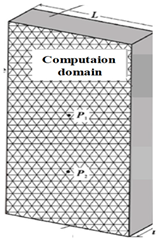
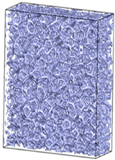
 Applsci 12 06995 i001 Applsci 12 06995 i002
Momentum equations [114,118] u t + ( u · ) ( ε 1 u ) = ( ε ρ f p ) + . ( ν f u ) + ε · F F = ( ν f K + F ε K | u | ) u g β ( T T r e f ) (14) u t + ( u · ) u = ( p / ρ f ) + . ( ν f u ) + F F = g β ( T T r e f ) (15)
Energy equations [114,118]For liquid phaseFor liquid phase
ε ( ρ C p ) f ( T f t + u · T f ) = . ( λ e f f , f T f ) + h s f a s f ( T s T f ) ε ρ f L a Γ t (16) ( ρ p H ) t + . ( ρ f C p u T f ) = . ( λ f T ) H = C p T f + f l L (17)
For solid phaseFor solid phase
( 1 ε ) ( ρ C p ) s T s t = . ( λ e f f , s T s ) + h s f a s f ( T f T s ) (18) ( ρ C p T ) s t = . ( λ s T ) (19)
Application conditionsMacroporous materialMacro/meso/microporous material
Flow field [160,162] Applsci 12 06995 i003 Applsci 12 06995 i004
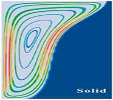
Thermal field [124,163] Applsci 12 06995 i005 Applsci 12 06995 i006
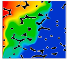
Evolution of solid/liquid phase interface [124,163] Applsci 12 06995 i007 Applsci 12 06995 i008
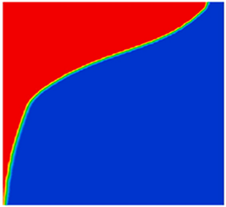
Publisher’s Note: MDPI stays neutral with regard to jurisdictional claims in published maps and institutional affiliations.

