
Unit Integration Method Solution and Experimental Research on Mechanism Characteristics for Flat Digging of Grab Dredgers

Abstract
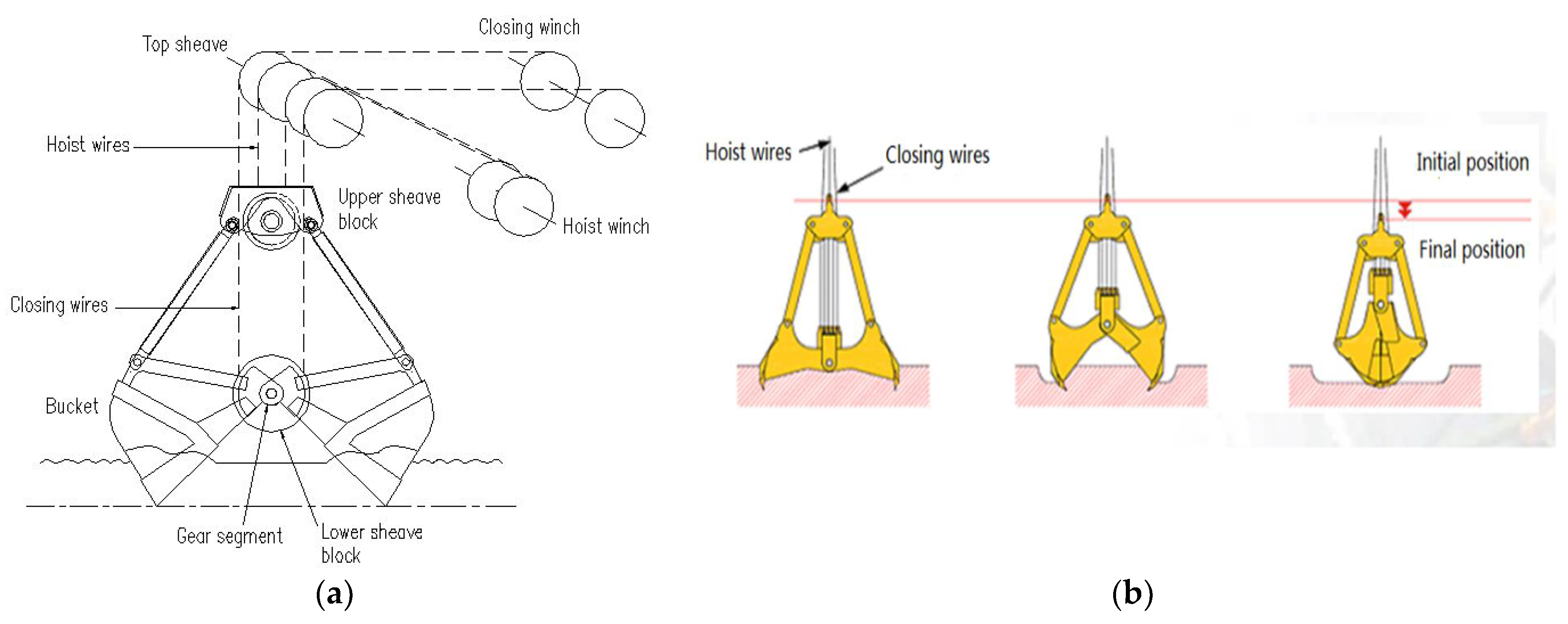
:1. Introduction
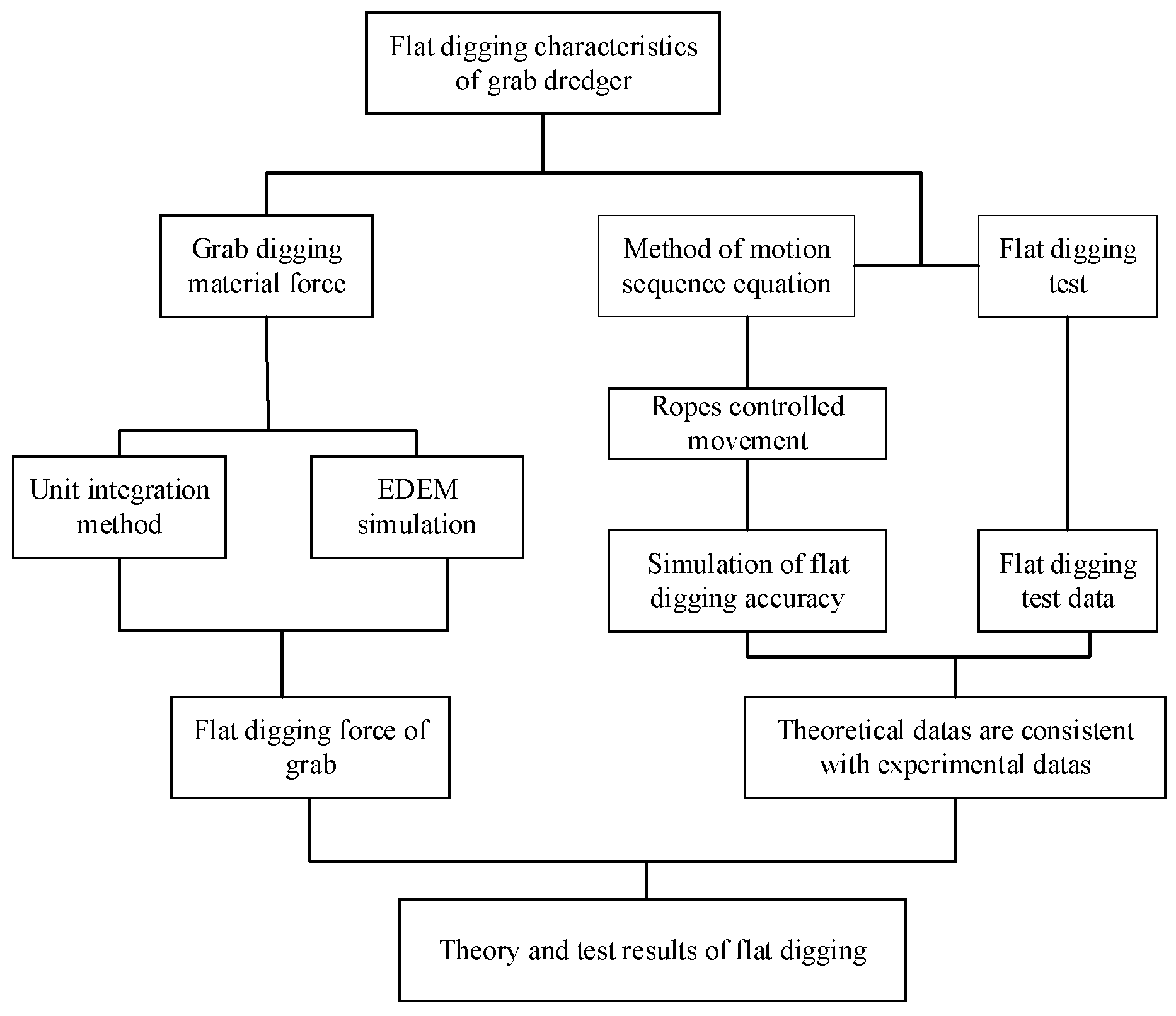
2. Theoretical Analysis and Experimental Details
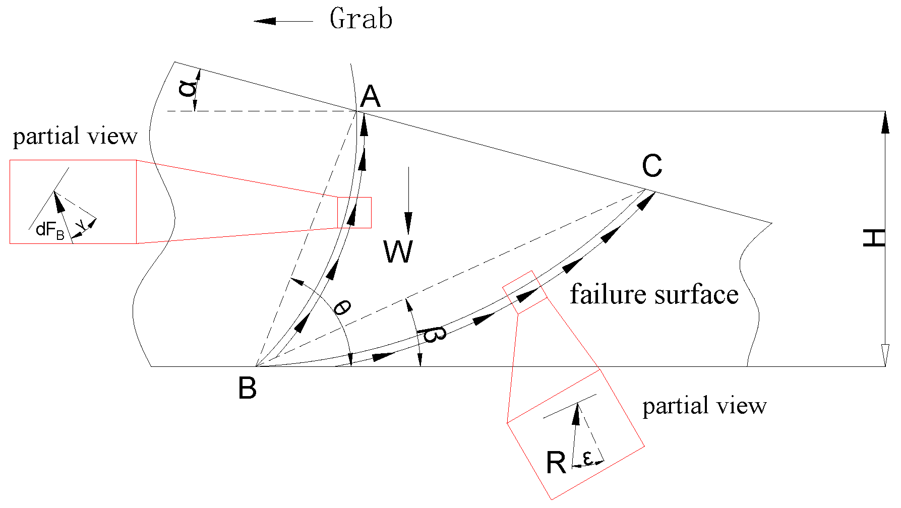
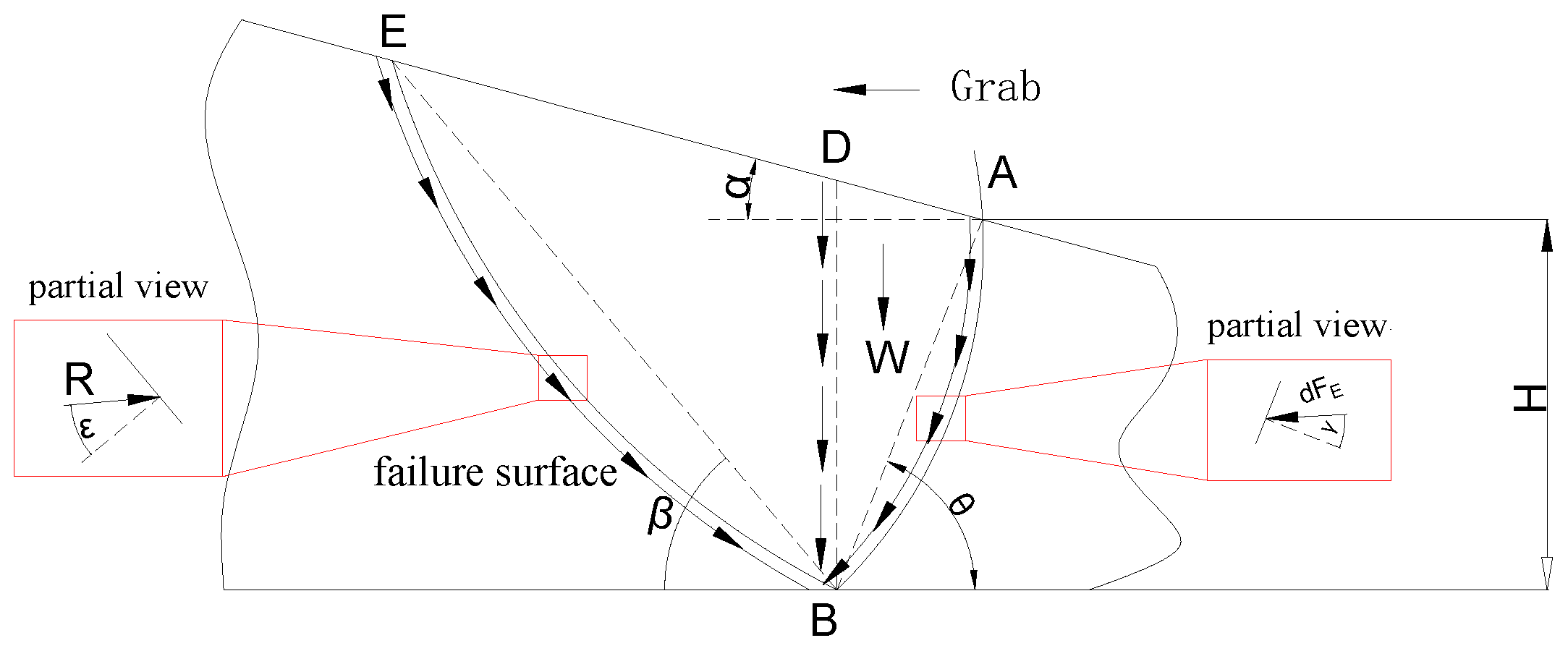
2.1. Theoretical Model Analysis of Digging
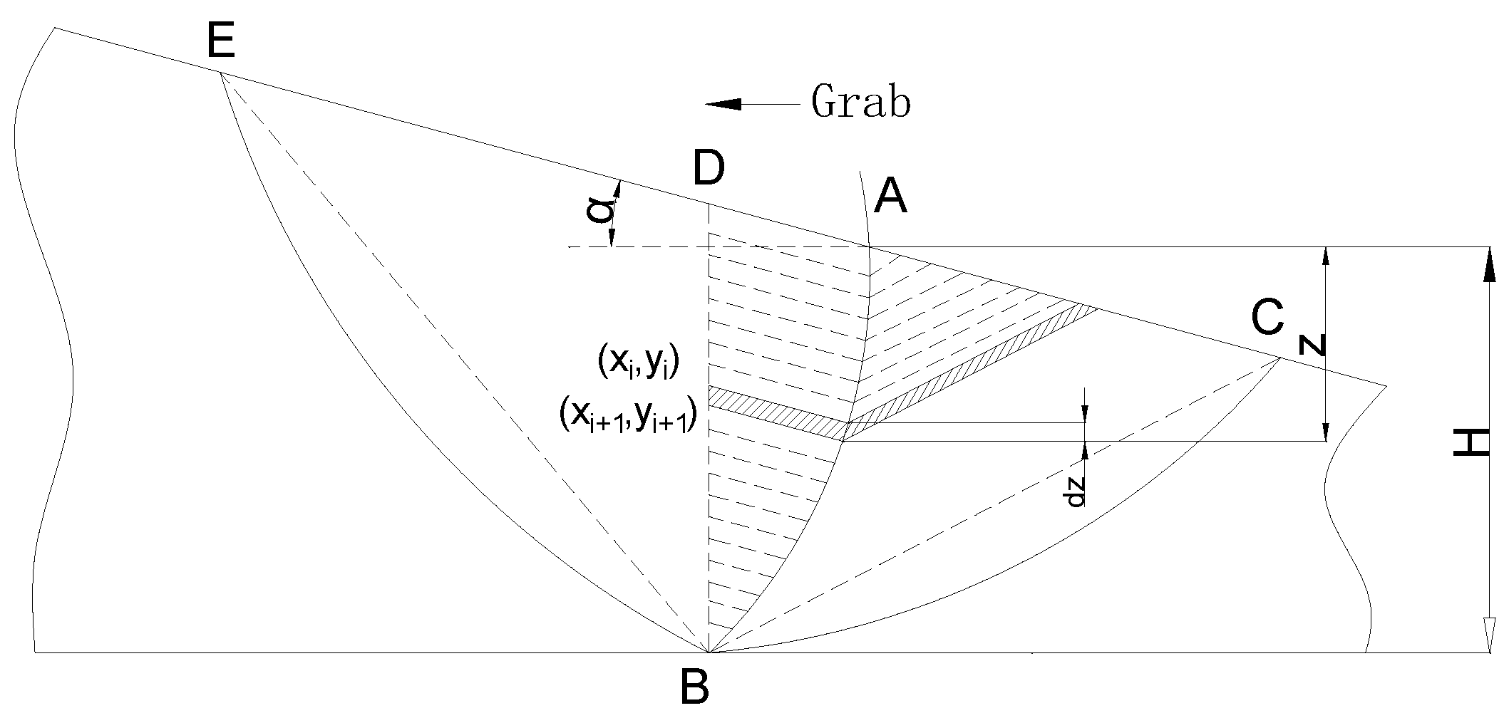
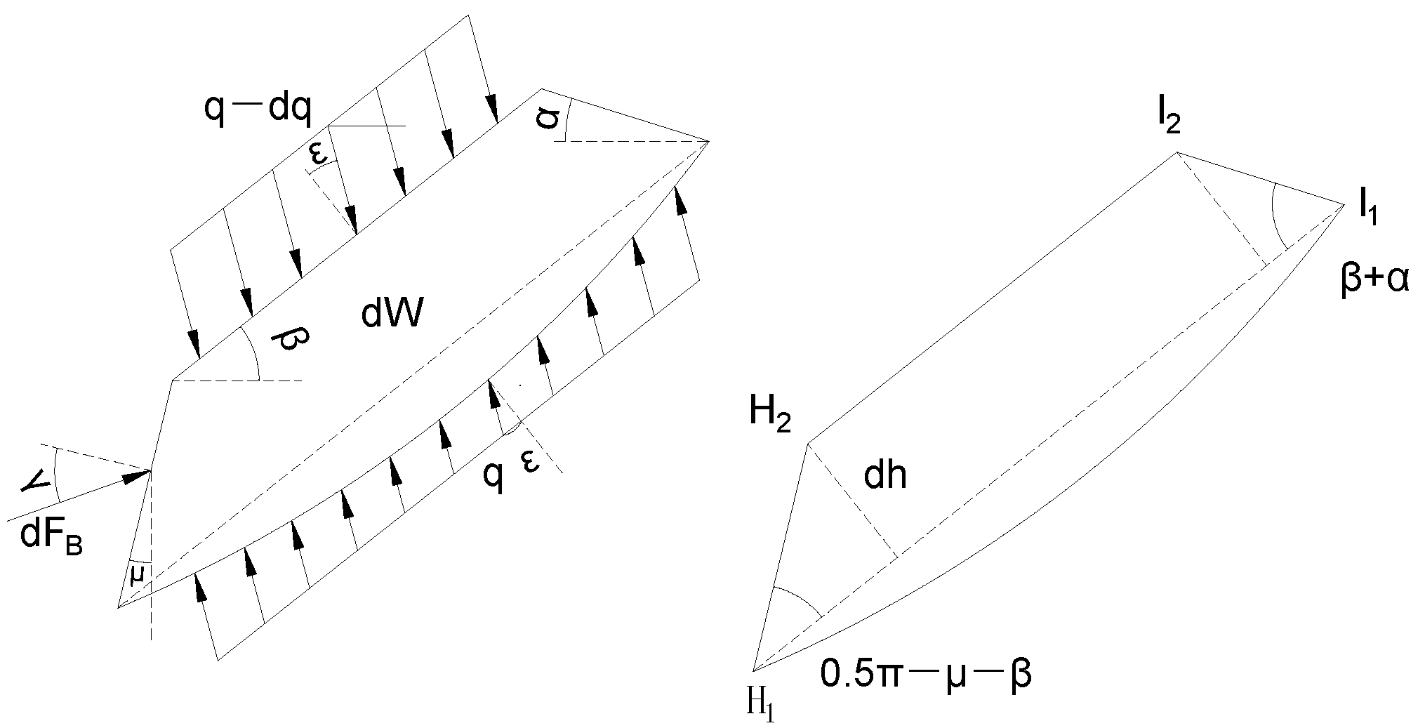
2.1.1. Active Material Pressure and Its Failure Surface
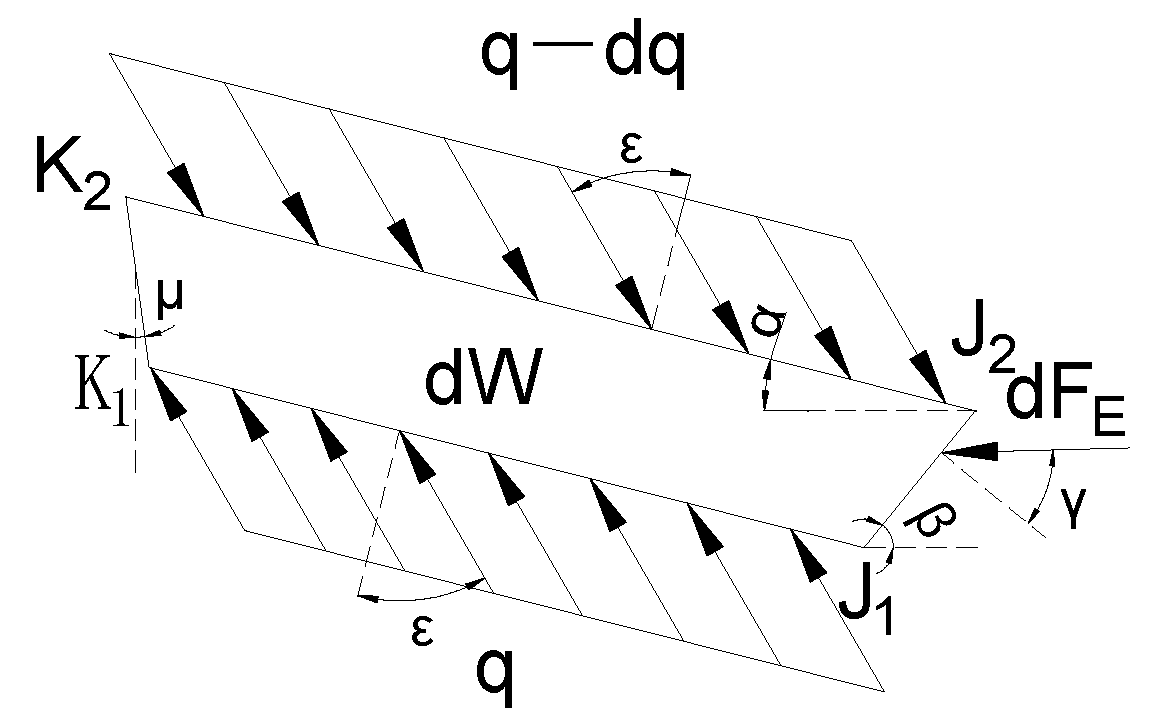
2.1.2. Passive Material Pressure and Its Failure Surface
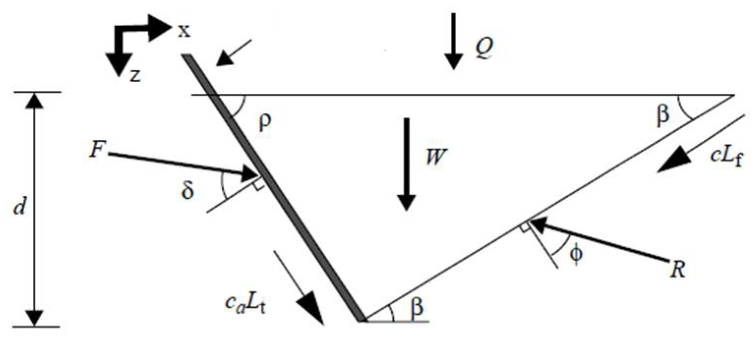
2.1.3. Analysis of Force Based on Unit Integration Method
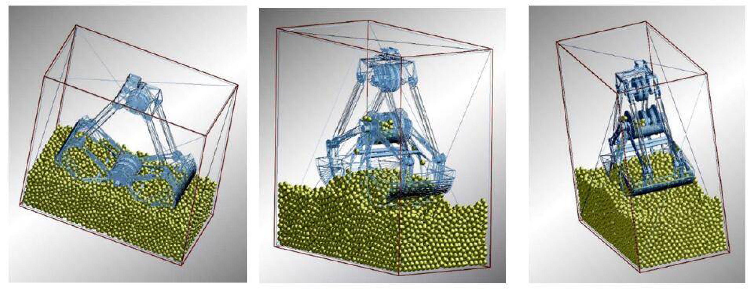
2.2. Mechanical Mechanism of Flat Digging Based on the DEM
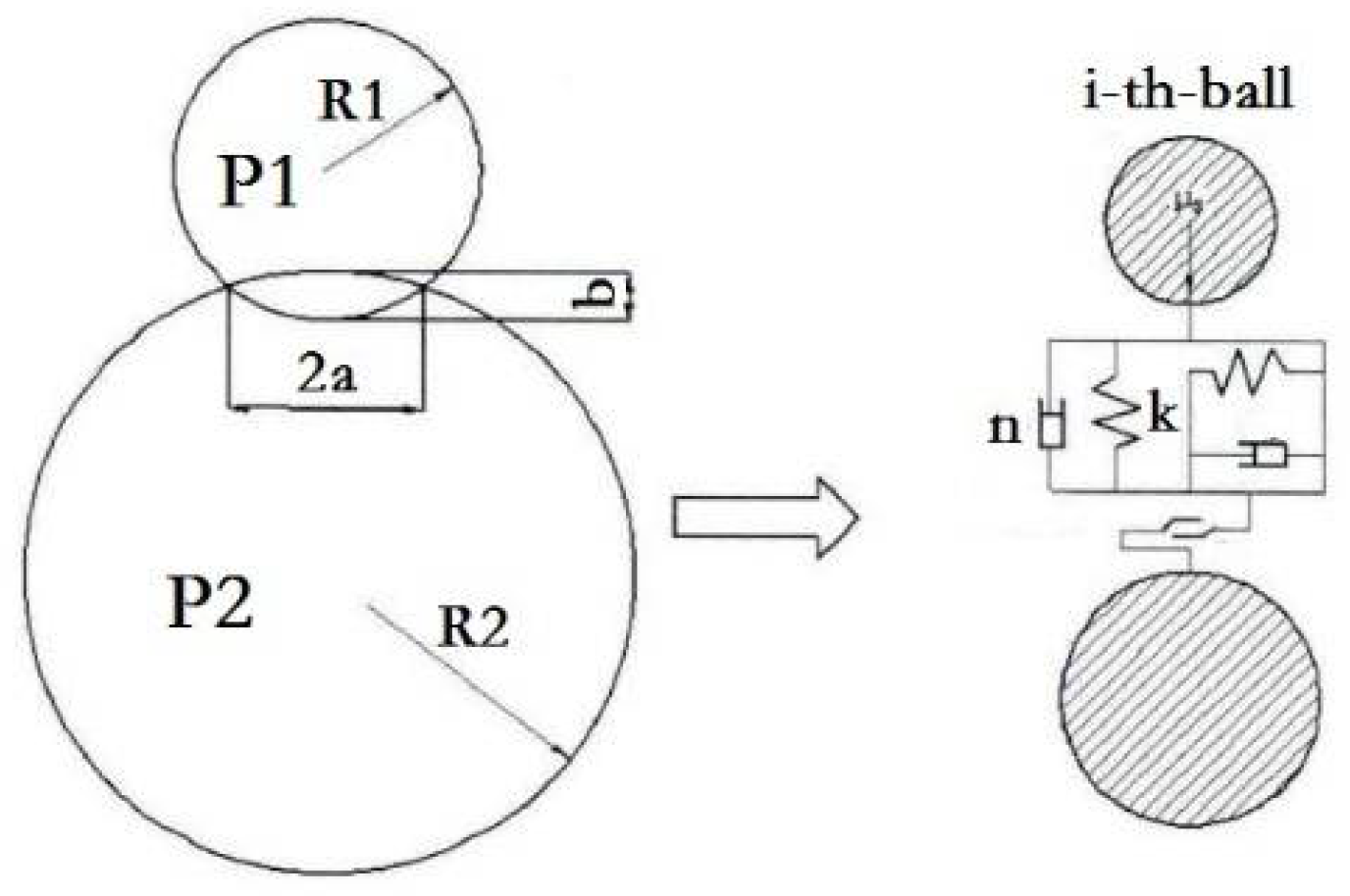
2.2.1. Particle Model of the DEM
2.2.2. Mechanical Numerical Simulation
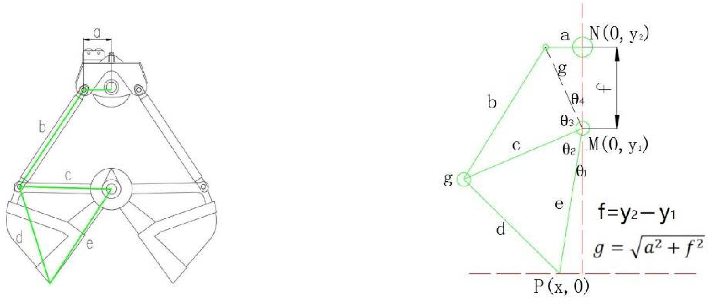
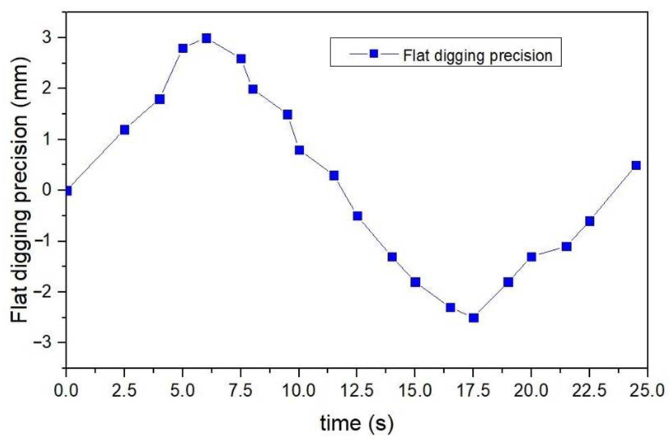
2.3. Theoretical Simulation Analysis of Flat Digging Precision
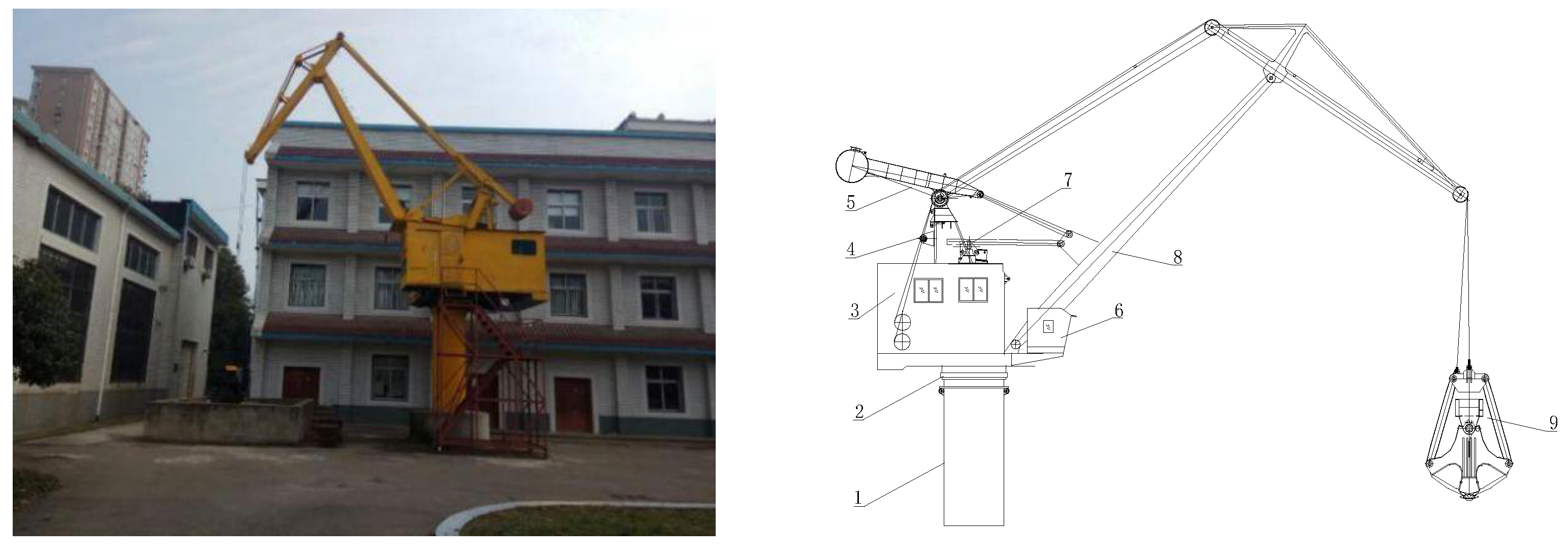
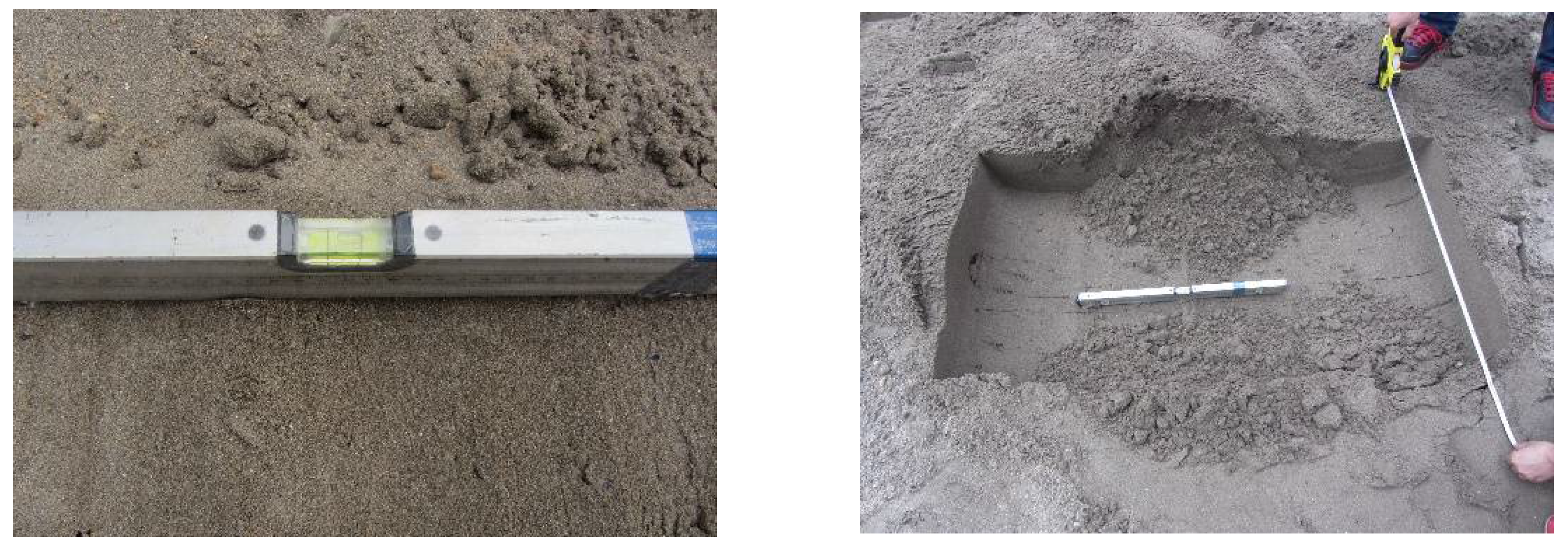
2.4. Flat Digging Experiment
3. Results
3.1. Theoretical Digging Resistance
3.1.1. Active Pressure
3.1.2. Passive Pressure
3.1.3. Digging Force
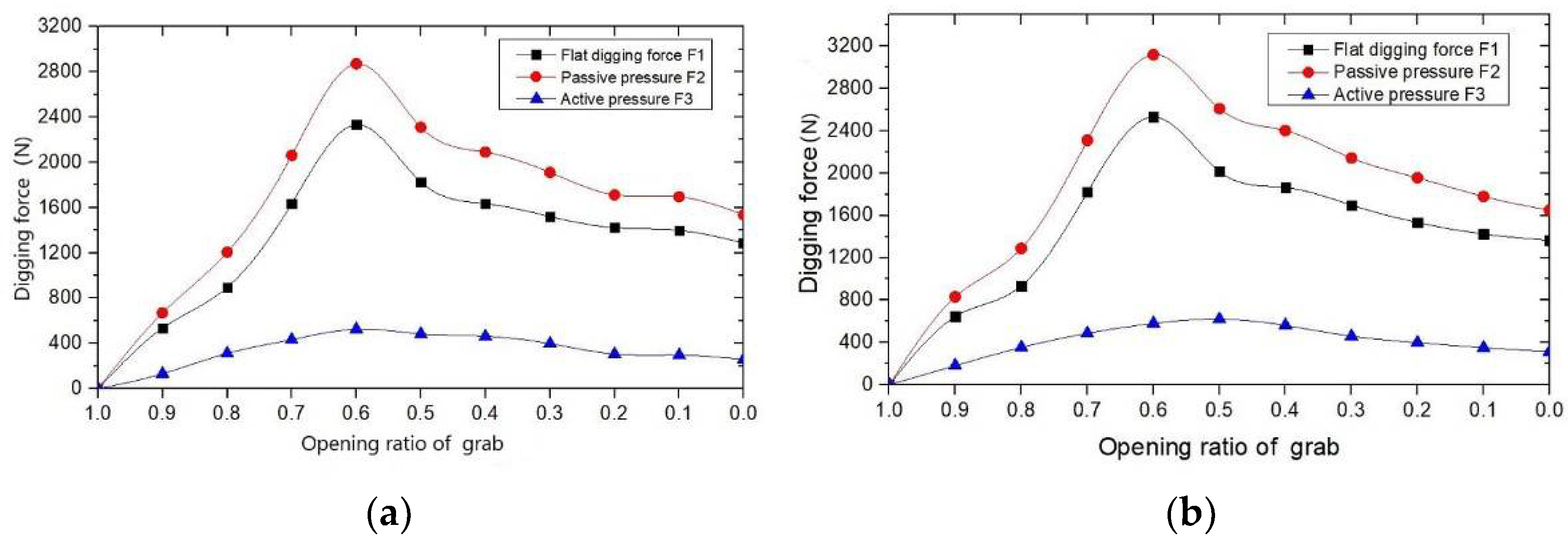
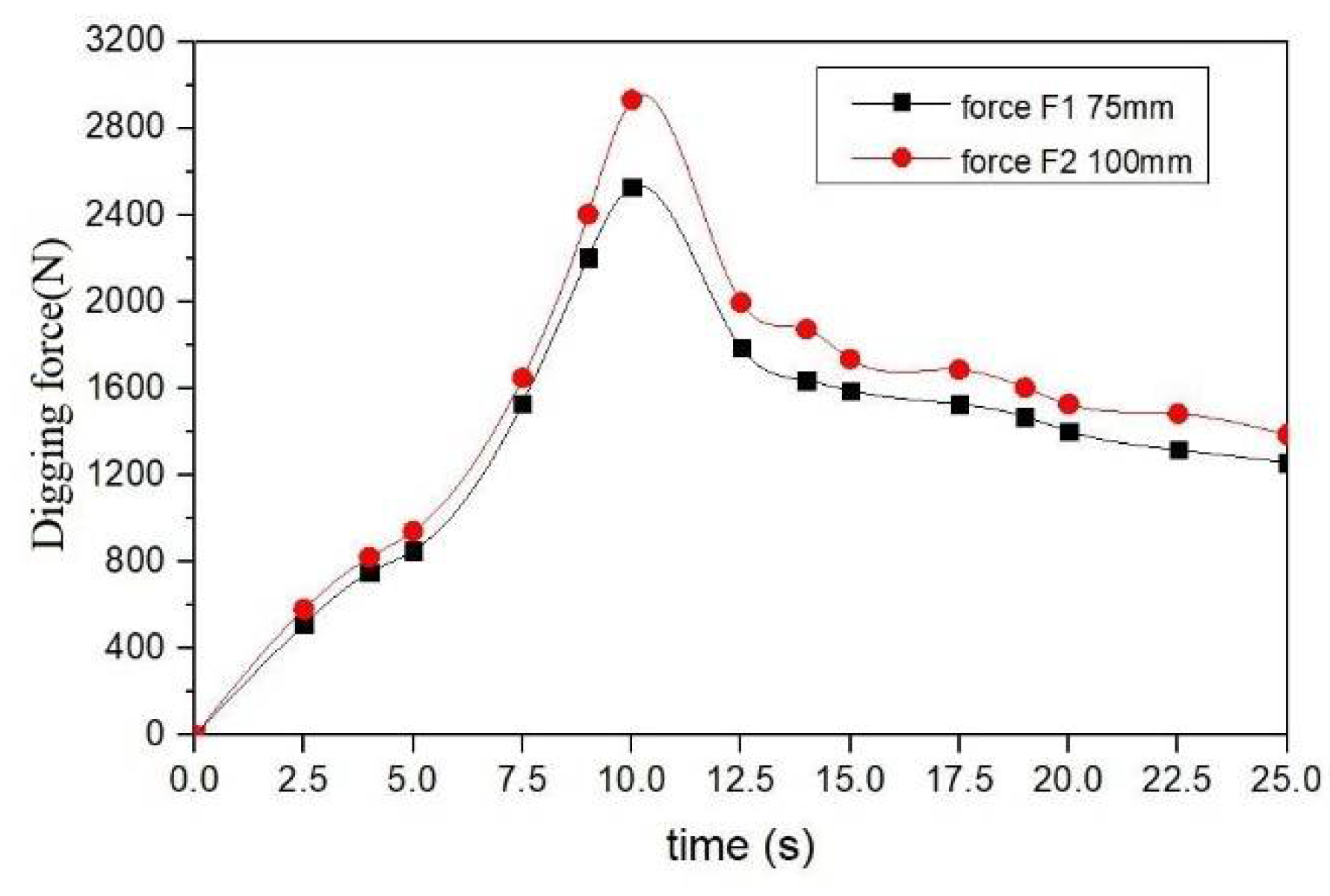
3.2. Simulation of Digging Force Value
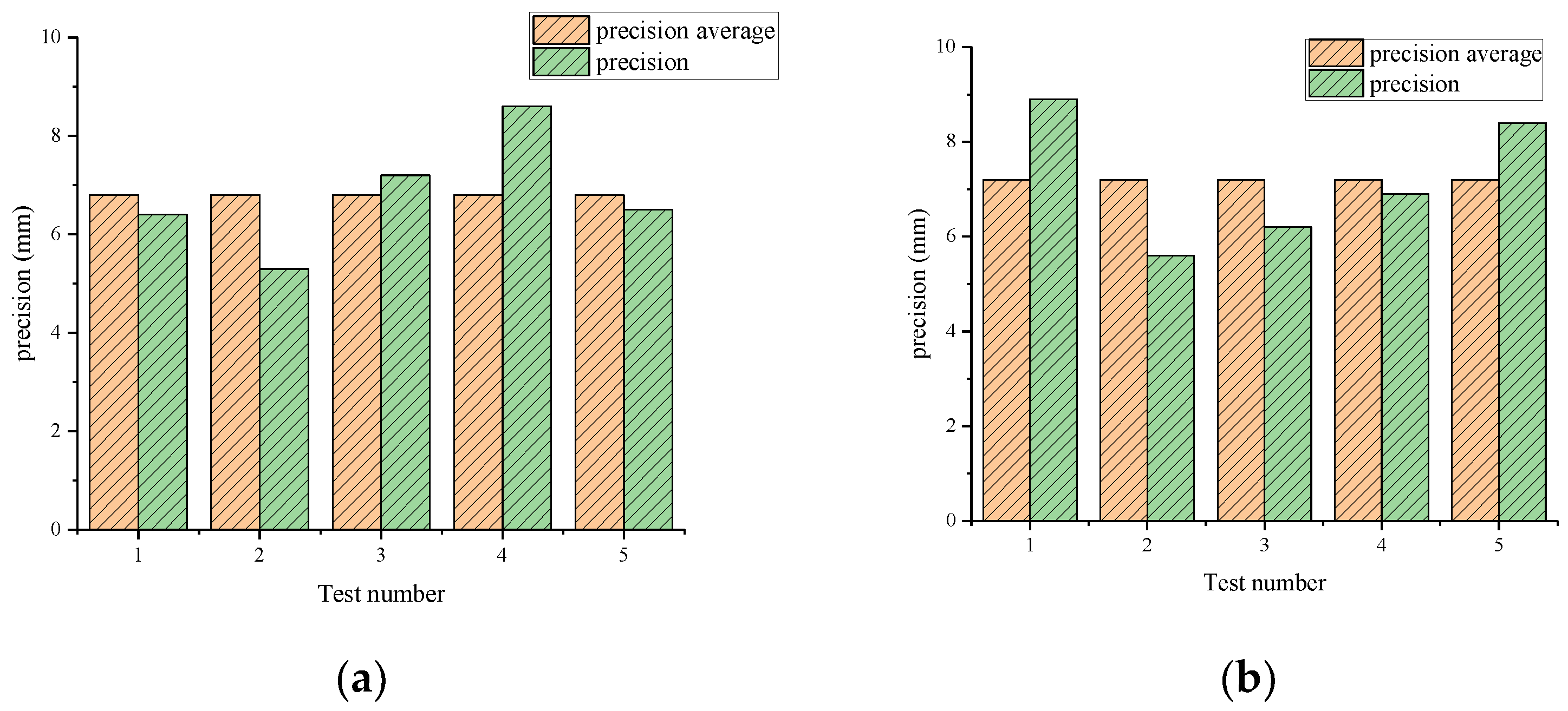
3.3. Flat Digging Precision Value
3.4. Flat Digging Experiment Results
4. Discussion and Conclusions
4.1. Discussion
4.1.1. Characteristics of Unit Integration Method
- (1)
- The grab has complex structural geometric parameters, and the analysis of the unit body mechanics model avoids the influence of the grab’s geometric parameters. Using the unit integration method, it can be converted into active pressure and passive pressure .
- (2)
- For the characteristic analysis of the interaction force between the grab and the material, the unit body model can consider the friction between the materials. The construction of the mechanical model of the grab excavating material is more consistent with the actual grab excavation mechanical model.
4.1.2. Characteristics of Flat Digging Control
4.2. Conclusions
- (1)
- In this paper, in contrast with traditional research on the force of grab excavation, the unit integration method for analyzing the force of the grab excavation material was proposed. During the excavation process of the grab, the force on the grab produced active pressure and passive pressure . and , as expressed by integral equations, and the material was divided into units. Digging force was obtained by subtracting and . Depending upon the characteristics of the material unit, this method can analyze the functional expression between the grab bucket digging force and the digging parameters.
- (2)
- Based on the DEM theory, the process of excavating materials with a grab was simulated. In the simulation process, reasonable data parameters were set, and the the grab flat digging force obtained. The simulation data shows that the digging force first increases and then decreases. Through comparative analysis, we found that the simulation results of the force of the grab flat digging are basically consistent with the theoretical calculation by the unit integration method, which verifies the correctness of the relevant theoretical models.
- (3)
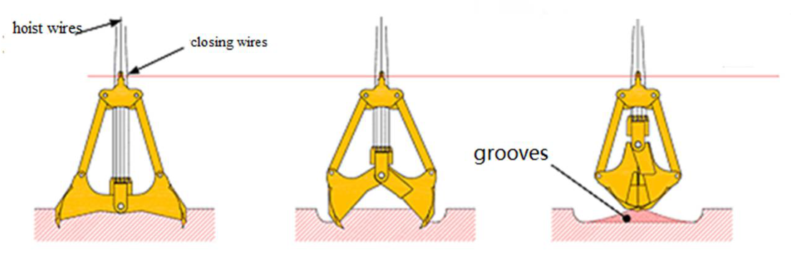
- This study sought to control the movement distance of the closing wires and the hoist wires through the equation of motion, to carry out theoretical precision calculations and experimental research into grab flat digging. A flat digging test was carried out on land in fine weather conditions. The flat digging test was carried out on both dry soil and wet soil, and both demonstrated similar precisions (6.8 mm vs. 7.2 mm) at a depth of 100 mm. By comparing theoretical data and test data, the following conclusion is drawn: the deviation of the theoretical flat digging precision from the test data falls within the allowable range, at 3.15%. It is already known that sea tests differ from land tests, but land tests provide a foundation—and can provide supporting data—for future sea tests. Such sea tests will be completed in our follow-up work, which will more realistically reflect the flat digging test.
Author Contributions
Funding
Institutional Review Board Statement
Informed Consent Statement
Data Availability Statement
Conflicts of Interest
References
- Xiao, H.; Xu, C.; Tao, D.; Xu, C. Research and Manufacturing of the 18 m3 Large Grab Dredger. Port Oper. 2015, 5, 14–16. [Google Scholar]
- Xu, C.; Xiao, H.; Zou, S.; Zeng, R. Research on Monitoring Force of Steel Wire Rope of Grab Dredger Base on Wireless Sensing. Procedia Eng. 2017, 174, 385–391. [Google Scholar] [CrossRef]
- Wang, Y. Theoretical and Experimental Research of Dredging Grab Flat-Digging Technique. Master’s Thesis, Wuhan University of Technology, Wuhan, China, 2013. [Google Scholar]
- Xiong, Q.; Xiao, H. Inverse Kinematics and Dynamics Simulation of a Dredging Clamshell. Appl. Mech. Mater. 2013, 364, 107–111. [Google Scholar]
- Parry, L.; Ashcroft, I.A.; Wildman, R.D. Understanding the effect of laser scan strategy on residual stress in selective laser melting through thermo-mechanical simulation. Addit. Manuf. 2016, 12, 1–15. [Google Scholar] [CrossRef] [Green Version]
- Ibarra, S.Y.; Mckyes, E.; Broughton, R.S. A model of stress distribution and cracking in cohesive soils produced by simple tillage implements. J. Terramech. 2005, 42, 115–139. [Google Scholar] [CrossRef] [Green Version]
- Khanal, M.; Elmouttie, M.; Adhikary, D. Effects of particle shapes to achieve angle of repose and force displacement behaviour on granular assembly. Adv. Powder Technol. 2017, 28, 1972–1976. [Google Scholar] [CrossRef]
- Xiao, X.; Joshi, S. Automatic toolpath generation for heterogeneous objects manufactured by directed energy deposition additive manufacturing process. J. Manuf. Sci. Eng. 2018, 140, 071005. [Google Scholar] [CrossRef]
- Xiao, X.; Waddell, C.; Hamilton, C.; Xiao, H. Quality Prediction and Control in Wire Arc Additive Manufacturing via Novel Machine Learning Framework. Micromachines 2022, 13, 137. [Google Scholar] [CrossRef]
- Xiao, X.; Roh, B.M.; Hamilton, C. Porosity management and control in powder bed fusion process through process-quality interactions. CIRP J. Manuf. Sci. Technol. 2022, 38, 120–128. [Google Scholar] [CrossRef]
- Xiao, X.; Xiao, H. Autonomous robotic feature-based freeform fabrication approach. Materials 2021, 15, 247. [Google Scholar] [CrossRef]
- Miedema, S.A.A. Sensitivity Analysis of the Production of Clamshells. WEDA J. Dredg. Eng. 2008, 9, 19. [Google Scholar]
- Chang, Q. Design of large-scale long-strut bulk cargo grab. Hoisting Conveying Mach. 1991, 5, 6. [Google Scholar]
- Ji, S. Research on Deformation Theory and Dynamic Simulation of Digging Process for Granular Materials. Ph.D. Thesis, Wuhan University of Technology, Wuhan, China, 2002. [Google Scholar]
- Zhang, H. Mechanical Property and Simulation Experimental Research of Dredging Grab. Master’s Thesis, Wuhan University of Technology, Wuhan, China, 2014. [Google Scholar]
- Xiao, X.; Joshi, S. Process planning for five-axis support free additive manufacturing. Addit. Manuf. 2020, 36, 101569. [Google Scholar] [CrossRef]
- Xiao, X.; Joshi, S.; Cecil, J. Critical assessment of Shape Retrieval Tools (SRTs). Int. J. Adv. Manuf. Technol. 2021, 116, 3431–3446. [Google Scholar] [CrossRef]
- Cleary, P.W.; Hilton, J.E.; Sinnott, M.D. Modelling of industrial particle and multiphase flows. Powder Technol. 2017, 314, 232–252. [Google Scholar] [CrossRef]
- Coetzee, C.J.; Basson, A.H.; Vermeer, P.A. Discrete and continuum modelling of excavator bucket filling. J. Terrramech. 2007, 44, 177–186. [Google Scholar] [CrossRef]
- Coetzee, C.J.; Els, D.N.J. Calibration of discrete element parameters and the modelling of silo discharge and bucket filling. Comput. Electron. Agric. 2009, 65, 198–212. [Google Scholar] [CrossRef]
- Coetzee, C.J.; Els, D.; Dymond, G.F. Discrete element parameter calibration and the modelling of dragline bucket filling. J. Terrramech. 2010, 47, 33–44. [Google Scholar] [CrossRef]
- Mitra, T.; Saxén, H. Discrete element simulation of charging and mixed layer formation in the ironmaking blast furnace. Comput. Part. Mech. 2016, 3, 541–555. [Google Scholar] [CrossRef]
- Nezami, E.G.; Hashash, Y.; Zhao, D.; Ghaboussi, J. Simulation of front end loader bucket-soil interaction using discrete element method. Int. J. Numer. Anal. Methods Geomech. 2007, 31, 1147–1162. [Google Scholar] [CrossRef]
- Wu, Z. Implementation and Simulation Study for Dredging Grab on the Working Condition of Flating Dredging. Master’s Thesis, Wuhan University of Technology, Wuhan, China, 2014. [Google Scholar]
- Biegler, M.; Graf, B.; Rethmeier, M. In situ distortions in LMD additive manufacturing walls can be measured with digital image correlation and predicted using numerical simulations. Addit. Manuf. 2018, 20, 101–110. [Google Scholar] [CrossRef]
- Wensrich, C.M.; Katterfeld, A. Rolling friction as a technique for modelling particle shape in DEM. Powder Technol. 2012, 217, 409–417. [Google Scholar] [CrossRef]
- Mckyes, E. Soil Cutting and Tillage; Elsevier Sciences: Amsterdam, The Netherlands, 1985. [Google Scholar]


| Parameters (Unit) | Value |
|---|---|
| Sand Poisson ratio | 0.5 |
| Sand shear modulus (Pa) | 1.0 × 10⁷ |
| Sand density (kg/m3) | 2650 |
| Steel Poisson ratio | 0.3 |
| Steel shear modulus (Pa) | 7 × 10¹⁰ |
| Steel density (kg/m3) | 7850 |
| Sand–sand restitution coefficient | 0.48 |
| Sand–sand static friction coefficient | 0.57 |
| Sand–sand rolling friction coefficient | 0.07 |
| Sand–steel restitution coefficient | 0.45 |
| Sand–steel static friction coefficient | 0.58 |
| Sand–steel rolling friction coefficient | 0.08 |
| Surface energy (J/m2) | 6.5 |
| Parameters (Unit) | Value |
|---|---|
| Sand density (kg/m3) | 0.5 |
| The angle of internal friction of sand (°) | 30 |
| Friction angle between sand and grab (°) | 20 |
| Cohesion (Pa) | 14,300 |
| Digging angle of grab (°) | Parameter solution |
| Test Number | Sand Proportion (t/m3) | Digging Depth (mm) | Flat Digging Precision (mm) | Precision Average (mm) |
|---|---|---|---|---|
| 1 | 1.45 | 100 | 6.4 | |
| 2 | 1.45 | 100 | 5.3 | |
| 3 | 1.45 | 100 | 7.2 | 6.8 |
| 4 | 1.45 | 100 | 8.6 | |
| 5 | 1.45 | 100 | −6.5 | |
| 6 | 1.86 | 100 | 8.9 | |
| 7 | 1.86 | 100 | 5.6 | |
| 8 | 1.86 | 100 | −6.2 | 7.2 |
| 9 | 1.86 | 100 | 6.9 | |
| 10 | 1.86 | 100 | 8.4 |
Publisher’s Note: MDPI stays neutral with regard to jurisdictional claims in published maps and institutional affiliations. |
© 2022 by the authors. Licensee MDPI, Basel, Switzerland. This article is an open access article distributed under the terms and conditions of the Creative Commons Attribution (CC BY) license (https://creativecommons.org/licenses/by/4.0/).
Share and Cite
Xu, C.; Li, Z.; Zhu, Z.; Li, Z. Unit Integration Method Solution and Experimental Research on Mechanism Characteristics for Flat Digging of Grab Dredgers. Appl. Sci. 2022, 12, 6968. https://doi.org/10.3390/app12146968
Xu C, Li Z, Zhu Z, Li Z. Unit Integration Method Solution and Experimental Research on Mechanism Characteristics for Flat Digging of Grab Dredgers. Applied Sciences. 2022; 12(14):6968. https://doi.org/10.3390/app12146968
Chicago/Turabian StyleXu, Chang, Zhe Li, Zhouyi Zhu, and Zhanfeng Li. 2022. "Unit Integration Method Solution and Experimental Research on Mechanism Characteristics for Flat Digging of Grab Dredgers" Applied Sciences 12, no. 14: 6968. https://doi.org/10.3390/app12146968
APA StyleXu, C., Li, Z., Zhu, Z., & Li, Z. (2022). Unit Integration Method Solution and Experimental Research on Mechanism Characteristics for Flat Digging of Grab Dredgers. Applied Sciences, 12(14), 6968. https://doi.org/10.3390/app12146968