Article

Fabrication of Cylindrical Microlens Array on RB-SiC Moulds by Precision Grinding with MAWJ-Textured Diamond Wheels

1
School of Mechanical and Electronic Engineering, Shandong Jianzhu University, Jinan 250101, China
2
Centre for Advanced Jet Engineering Technology (CaJET), School of Mechanical Engineering, Shandong University, Jinan 250061, China
3
Key Laboratory of High Efficiency and Clean Mechanical Manufacture, Shandong University, Ministry of Education, Jinan 250061, China
*
Authors to whom correspondence should be addressed.
Appl. Sci. 2022, 12(14), 6893; https://doi.org/10.3390/app12146893
Submission received: 20 May 2022 / Revised: 29 June 2022 / Accepted: 5 July 2022 / Published: 7 July 2022
(This article belongs to the Special Issue New Frontiers in Grinding Processes)

Abstract

:
Cylindrical microlens array (CMA) is applied widely in imaging, sensing, and laser machining fields. Among the many techniques for machining CMA, moulding is considered a mass-production method with low-cost and good accuracy. Aimed at the present problems in the machining of CMA moulds, which include low processing efficiency and the prediction of the surface topography, this paper focused on the fabrication of CMA on RB-SiC moulds by precision grinding with micro-abrasive water jet (MAWJ) textured diamond wheels. The combined rough–fine grinding strategy for ceramic mould materials was proposed. The grinding experiments of CMA were carried out. The ultra-precision grinding method was optimized to obtain high shape accuracy and a high-quality surface of RB-SiC moulds. It was found that by using MAWJ-textured diamond wheels, the profile error in the peak-to-valley value (PV) of the CMA moulds can be further reduced to 6.7 μm by using the combined rough–fine strategy grinding process.

1. Introduction

The pattern of the laser beam profile is represented as a similar Gaussian intensity shape, followed by a dynamic spatial energy distribution according to the beam generation mechanism [1]. Nevertheless, several popular applications for a uniform intensity distribution would be desirable. For instance, a uniform intensity distribution in manufacturing materials means that the whole laser-lighted area is uniform. It is also useful in cases where laser light is mainly utilized for lighting. This is because consistent illumination gives identical features the same brightness regardless of where they are in the illumination field; thus, the image-processing task is simplified, and the contrast and resolution are improved. These same advantages extend to broad applications, not only in scientific studies but also in medicine.
There are many strategies to convert a Gaussian beam into a uniform intensity distribution, such as spherical microlenses, freeform lenses, and aplanatic optics. Shaoulov proposed using micro-lenslet arrays to overcome the restriction in the size of optical systems [2]. Babadi proposed a novel circular dielectric internally reflecting optic, which can produce over 95% uniformity within an illuminated area [3]. Mashaal presented a promising representative design for LED collimation [4]. Compared to free-form lenses, microlenses and CMA can overcome the restrictions in size to create extremely compact and lightweight optical systems. CMA not only has the function based on spherical microlens array but can also achieve a performance with a long focal depth and high lateral resolution. It can improve the output efficiency of OLEDs and the image quality at the same time. One of the most effective and flexible approaches is using a CMA. However, the fabrication of a CMA with complex features brings huge challenges to optical applications. Various techniques for manufacturing CMAs [5,6,7,8,9,10,11,12,13,14,15,16,17,18] are still being developed. The manufacturing techniques can be categorized into nonmechanical and mechanical methods based on the properties of material removal. The comparison of different manufacturing techniques for microlenses is summarized in Table 1.
The most commonly nonmechanical methods contain reactive ion etching [8], photolithography [10], and femtosecond direct writing technology [11,12]. However, these methods are restricted by manufacturing with expensive devices, particular materials, and time-consuming production procedures [13,14]. Furthermore, available lens geometries are limited, and these current machining methods have difficulty achieving the shape accuracy in lens arrays [15,16]. To realize the production of low-cost and high-precision lenses, ultra-precision machining methods are widely used in manufacturing moulds, including glass moulding and film rolling moulds [17]. However, the high rigidity and brittleness of glass make it difficult to machine by the roll-to-roll method. In modern industry, glass moulding has become an important replication-based technology for mass manufacturing these optical glass components [18]. Since the precision and quality of the machined surface will be directly reflected on the products, the structural mould still needs to be processed with ultra-precision machining technology to ensure that CMA has a high quality of the surface and precision. The ceramics (e.g., silicon carbide (SiC) and silicon nitride (SiN)) have excellent material properties, such as high wear resistance, great chemical stability, high thermal conductivity, high hardness, and high strength [5]. Increasingly, moulds are made of ceramics (such as SiC and SiN) rather than traditional metal materials. Furthermore, due to the high wear resistance and strength, it is extremely hard to machine micro-patterns on the ceramic surface.
The advanced processing method with micro-textured diamond grinding wheels offers a highly efficient and competitive solution which converts a micro-texture into a micro-pattern on the ceramic surface [19,20]. However, it is difficult to machine a precise wheel profile due to their wear-resistant characteristics. Thus, to obtain the desirable curve accuracy, the texturing process becomes very important for these wheels.
The micro-abrasive water jet (MAWJ) machining method was aimed at realizing the grinding wheel’s thermal nondamaging and efficient dressing. It has been presented in the previous research on dressing grinding wheels that this abrasive waterjet method can dress the grinding wheel efficiently and achieve the thermal nondamaging ablation of grinding wheel materials [21,22]. Nevertheless, this method is infrequently used in dressing micro-textured grinding wheels. It is critical to use this method to obtain micro-textured on the grinding wheel. The result expresses that the wheel surface characteristics with high protrusion can be acquired when applying this method to dress the grinding wheel [23]. Therefore, MAWJ technology is considered a promising texturing method. The dwell time algorithm calculation plays an essential role in obtaining the great precision profile of micro-textured wheels. The algorithm is based on the foundation that the intended material removal quantities are a convolution operation of dwell duration and removal function. Numerous algorithms have been designed for the development of sub-aperture optical manufacturing technology. Their removal functions mostly have a circular symmetrical distribution, including traditional pitch lap [24], stressed lap (S.L.) [25], reactive atom plasma [26], and ion beam figuring (IBF). It is based on the fundamental concept of Computer-Controlled Optical Surfacing (CCOS). The material-removal process is a 2D convolution of the spatial domain. Because of the previous surface profile inaccuracy and the influence function, the dwell time can be obtained by deconvolution [27]. The algorithms are primarily based on the discrete convolutional and linear equation models. Different models will inevitably result in different dwell-time algorithms. Therefore, the dwell time solution becomes the most important strategy for ensuring high-accuracy texturing diamond wheels.
In this work, a sinusoidal microlens array was used to realize the uniform intensity distribution of optical systems. The parameters of the CMA and the corresponding homogenization performances were first simulated using the ray-tracing software ZEMAX. A novel method based on the combined rough–fine grinding process using MAWJ-textured diamond wheels is proposed to fabricate CMA on RB-SiC moulds. A linear matrix equation is studied to build a stable dwell time algorithm for wheel texturing. An MAWJ texturing experiment is taken to demonstrate the effectiveness of the algorithm. The grinding experiment on RB-SiC is carried out to analyze the profile accuracy and ground surface topography.

2. Simulation and Experiments Methods

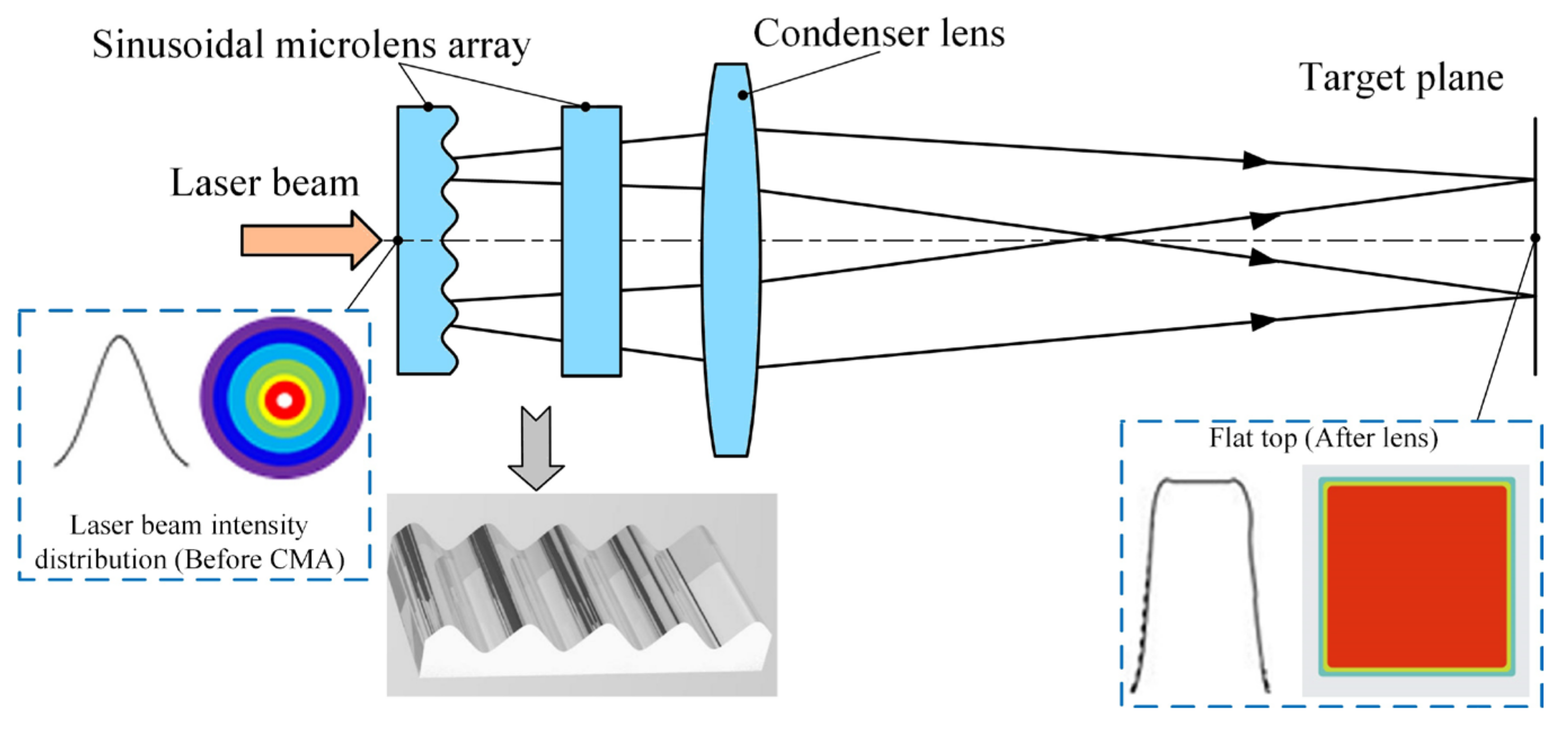
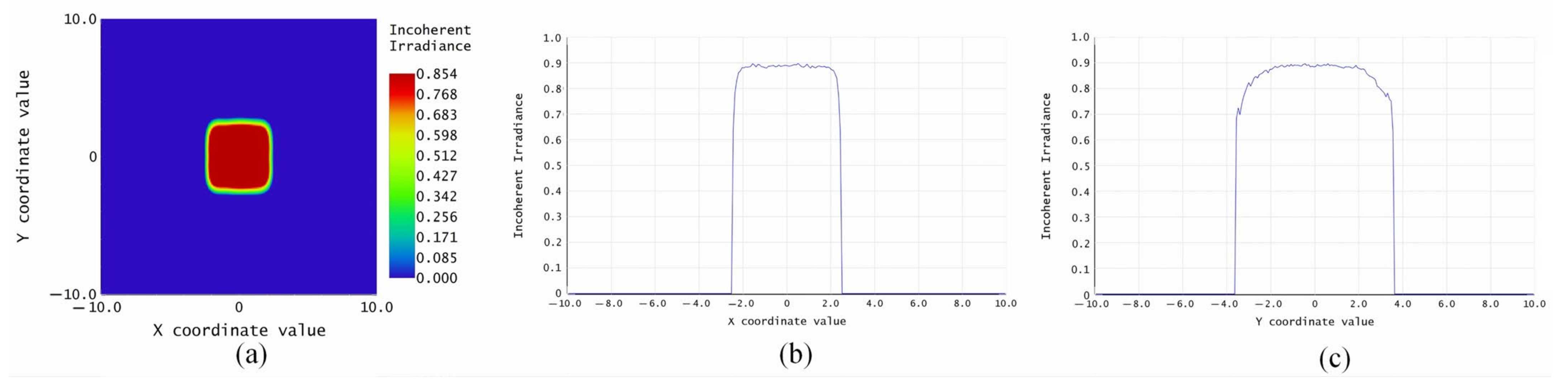
2.1. Design and Optimization of CMA

To investigate the optical effects of CMA, optical phenomena of reflection and refraction of the sinusoidal microlens array were analyzed using the ray-tracing software ZEMAX®. Figure 1 illustrates the schematic of the optical CMA homogenizer constructed in ZEMAX® software. The microlens array beam homogenizer usually contains two lens arrays and a condenser lens, which will have much greater flat-top uniformity. The incident beam cross-section is split into an array of beams by a sub-microlens array. Both beamlets then pass through the condenser lens, converge, and overlap at the same location. With the involvement of the second microlens array, every microlens, in conjunction with the condenser lens, may have a field lens effect. The lens array can produce overlapping pictures on the illumination plane of different kinds of fields of the light source. Due to the field lens effect, rays in all directions can be refracted to the desired location of illumination. Since for the beam generation mechanism the pattern of the excimer laser beam profile is rendered as an irregular shape, also accompanied by complex spatial energy distribution, the image framework as a design infrastructure is a good choice [28].
It should be noted that general imaging homogenizers are often two similar microlens arrays parted by the focal length, but this is not a feasible solution for the excimer laser. Due to the high average strength of the excimer laser beam in the UV to DUV region, the light can be easily absorbed by materials. The second microlens array can be connected by the concentrating energy of the first microwave array using only two identical microlens arrays configuration.
After optimizing all parameters of the optical system, an ideal distribution of light energy intensity was obtained on the optical detector in the mean beam plane. The shaping beam effect is shown in Figure 2. The corresponding parameters are shown in Table 2. The light intensity distribution of this point was analyzed through the spot coordinates in the detector to achieve an ideal degree of uniformity. The undulating state of the light spot energy was considerably reduced, and the optimized light intensity distribution curve is presented in Figure 2a. As shown in Figure 2b,c, the spatial distribution of the beam energy with a flat top is ideal. The calculated light intensity of the flat-top is 0.80; the light intensity difference is within 12%, that is, the relative light intensity is 88% to 100%; and the light intensity error is lower than 6%. Furthermore, the highly consistent beam profile with a huge scale is generated at a very close distance.

2.2. Fabrication of the CMA Mould

CMA moulds were fabricated by the combined rough–fine grinding, as illustrated in Figure 3. The operations are selected for rough grinding with a metal-bonded grinding wheel (600#), and the resin-bonded grinding wheel (3000#) was selected for fine-grinding CMA moulds. The micro-textured grinding wheels were employed in grinding RB-SiC moulds. Compared with the existing ultrathin arc-shaped diamond wheel grinding process, the proposed technology is more efficient in the fabrication cycle, benefiting from the new tool-clamping method. It can complete the rough–fine processing of CMA moulds in one cycle without multiple dressings and reduce the machine and auxiliary time. Detailed texturing information can be found in Section 3. During the machining process, the metal-bonded and resin-bonded diamond wheels are fixed on the grinder spindle, and the gasket is placed between the grinding wheels to prevent interference, shown in Figure 4.

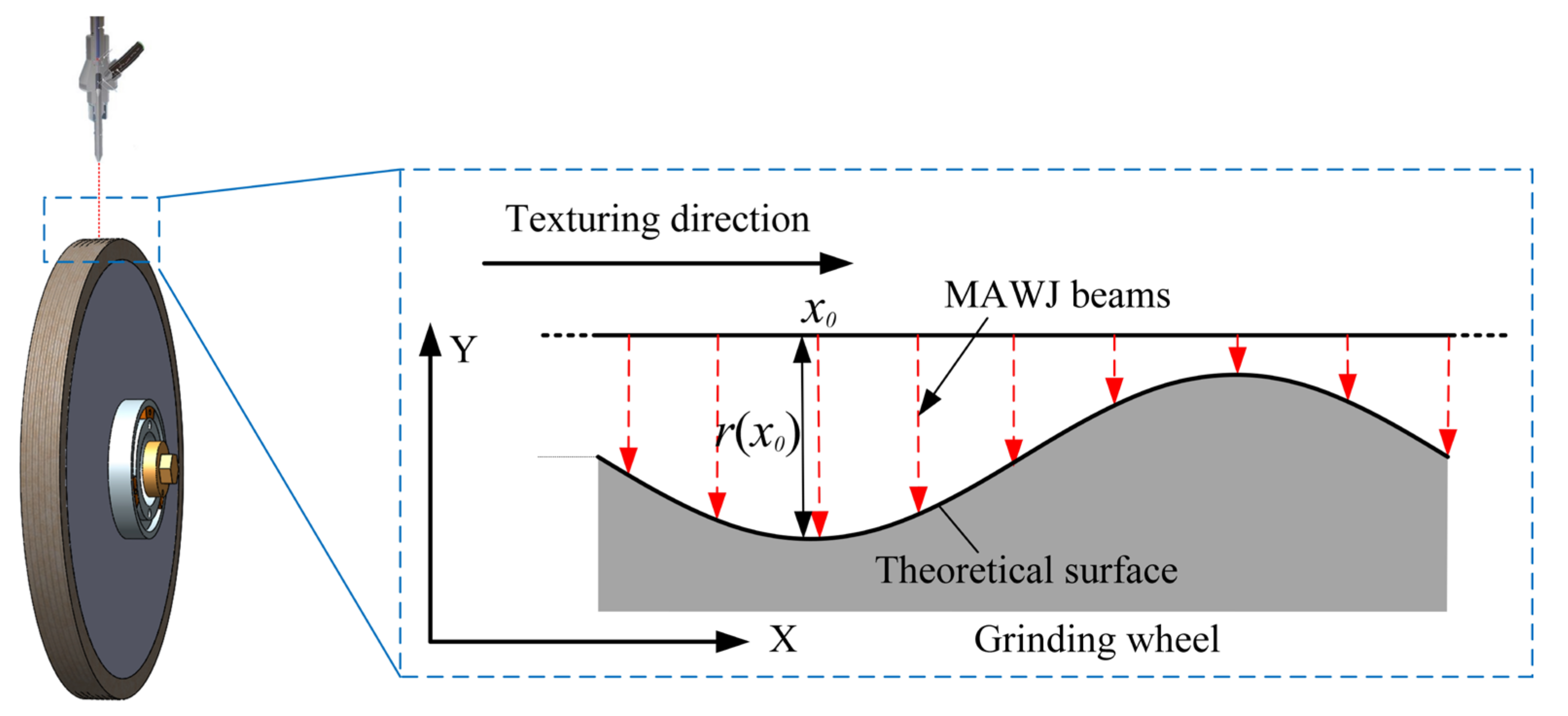
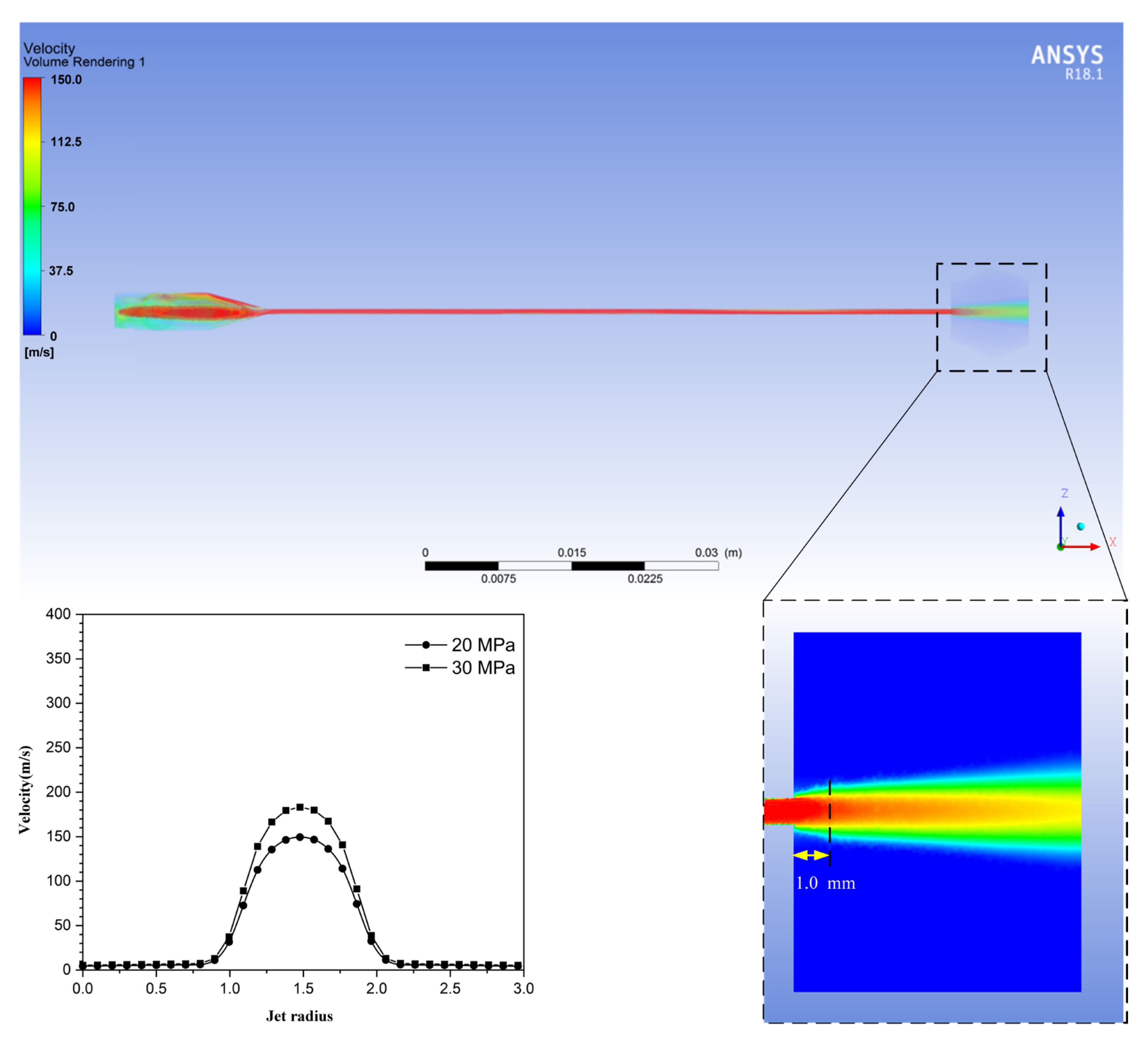
3. Texturing Principle of Diamond Grinding Wheels

During the texturing procedure, the ideal surface micro-texture is produced by controlling the removal volume at various spots on the surface of the grinding wheel. Material removal of the texturing process can be described as a convolution along a dressing path and dwell time, as illustrated in Equation (1):
b(x) = r(x) ⨂ t(x)
where r(x) is a material removal function per unit of time, and t(x) is the function of dwell time. The assumption on the constant for MAWJ process parameters is expected to result in a long-term reliable removal function. If only the number of dwell points was given, the dwell time could be solved based on the target values. The removal volume is a convolution of the removal function and dwell time [29].
In texturing process, Figure 5 presents the algorithm to solve the dwell time. When the AWJ influences the function fix at the point x 0 , the value of material removal at every place x in the space domain per unit of time can be expressed as r x x 0 . Assuming that the dwell time is at point x, then the value of material removal at position x can be represented as:
b 0 x = r x x 0 t x 0
When MAWJ scans the whole dwell area on the wheel surface, the actual amount of material removed at a specific point can be expressed as:
b x = x 0 = 0 x 0 = n 1 r x x 0 · t x 0
where n is the overall amount of dwell points of the generatrix grinding wheel. r x x 0 is the value of material removal per unit time at the point x 0 when the middle of MAWJ dwells at the point x , and t x 0 is the dwell time.
The MAWJ removal function can represent the machinability characteristic of a texturing procedure. The abrasive water jet removal function was based on predicting the location of impact velocity on a wheel surface using erosion maps generated by CFD. The material removal function R(x) is related to many factors such as water pressure, standoff distance, abrasive flow rate, wheel speed, and material properties of the grinding wheel, as presented in previous work [30]. The volume of fluid (VOF) model was used to simulate the field of the solid–liquid two-phase flow inside and outside the abrasive water jet nozzle. The boundary condition was set in the erosion model of ANSYS Fluent to obtain the three-dimensional erosion maps shown in Figure 6. The removal function is cosine distributed with high stability. Figure 6 compares the anticipated axial jet velocity distributions in the 1 mm standoff distance exiting the pressure for 20 MPa and 30 MPa. The jet velocity in 1 mm standoff distance (i.e., the apex of the profiles) was lower for the 20 MPa pressure than the 30 MPa. Thus, for the same standoff distance, the jet velocity of the larger pressure would be increased during impact, improving the kinetic energy of impacting particles.

4. Experimental Work

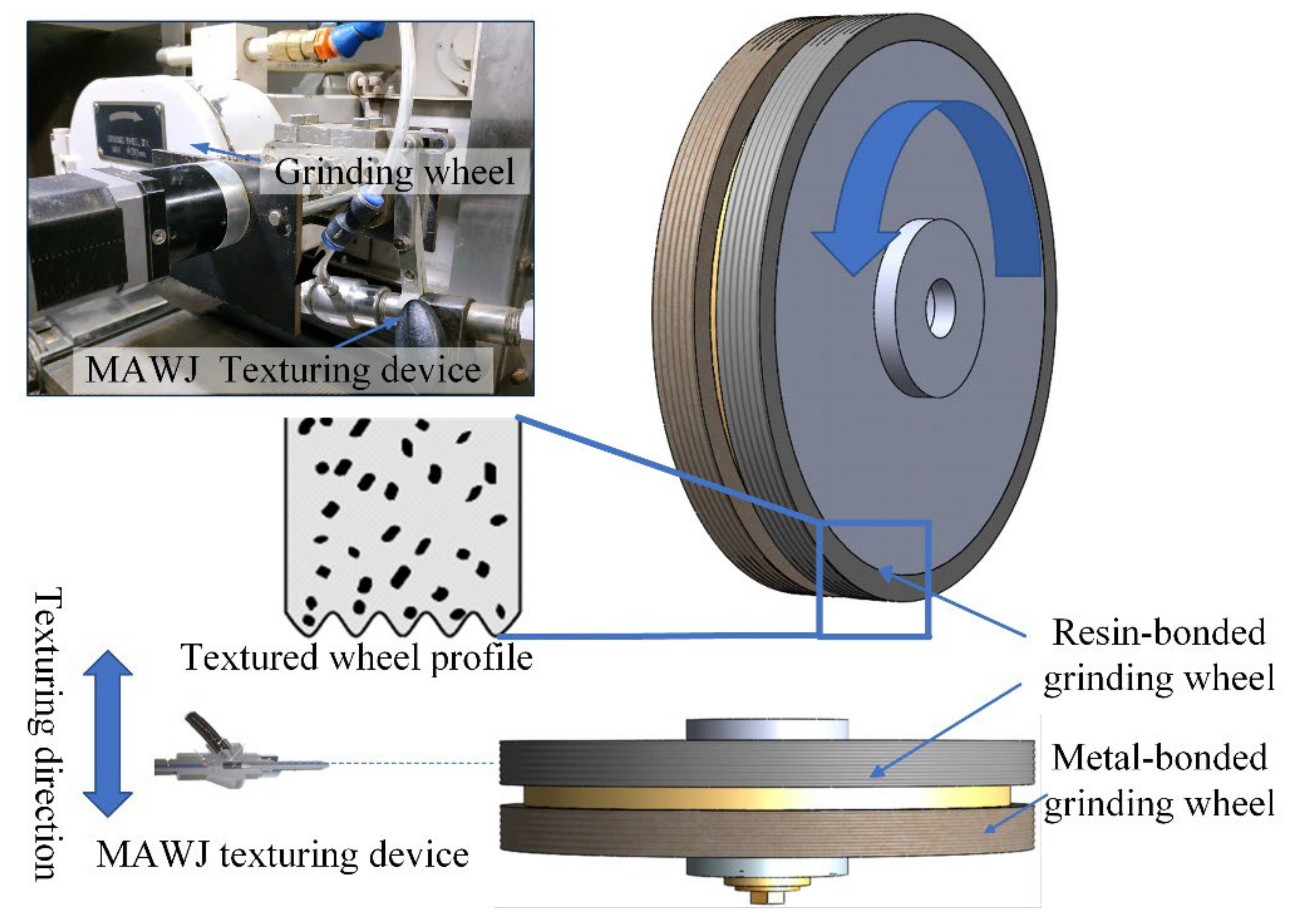
4.1. Texturing of Diamond Grinding Wheel

The MAWJ texturing system is shown in Figure 7. The texturing device is fixed on the CNC machine to achieve the micro-textured grinding wheel in situ. The 600# metal bond diamond wheels and 3000# resin bond diamond wheel were used in the experiment. The grinding wheels have a diameter of 200 mm with a concentration (Designating the amount of diamond or CBN in super abrasive wheels based on carats per centimeter) of 125%, and the thickness is 10 mm.
The removal function experiments were carried out according to Section 3. The removal functions for 600# metal bond diamond wheels and 3000# resin bond diamond wheels are given:
r M x = 0.0126 cos 1.2658 π x mm / m i n x 0.4 , 0.4 r B x = 0.056 cos 1.2658 π x mm / m i n x 0.4 , 0.4
where r M and r B are the removal functions per unit time of metal bonded and resin bonded grinding wheels, respectively.
MAWJ parameters (wheel speed, water pressure, and standoff distance) were selected by the texturing requirements. The MAWJ texturing parameters are summarized in Table 3. The structure of the diamond wheel was given by grinding a block of graphite materials. We reveal the topography of the grinding wheel by grinding a line on the graphite. A three-dimensional laser scanning device (VK-X200K) was used to measure the structure of the grinding wheel recorded in the graphite block.

4.2. Grinding of CMA Mould

The experiments of grinding RB-SiC moulds were performed on an ultra-precision surface profile grinder NAS-520X-CNC. The dressing and grinding were carried out under the axial and radial accuracy of 0.1 μm. Figure 8 shows the grinding test setup. The prepared RB-SiC specimen was rectangular, measuring 12 mm long, 8 mm wide, and 4 mm thick. The test process is the up-cut surface grinding of RB-SiC. Details of the rough grinding and fine grinding parameters are listed in Table 4 and Table 5, respectively. After grinding, the 3D laser confocal microscope was used to observe the ground surface of RB-SiC and measure the irregularity of the surface. After generating the three-dimensional texture structure, the two-dimensional surface profiles in different directions were acquired from the deepest location of the structure to obtain the geometric information of the CMA mould.

5. Surface Accuracy and Topography Analysis

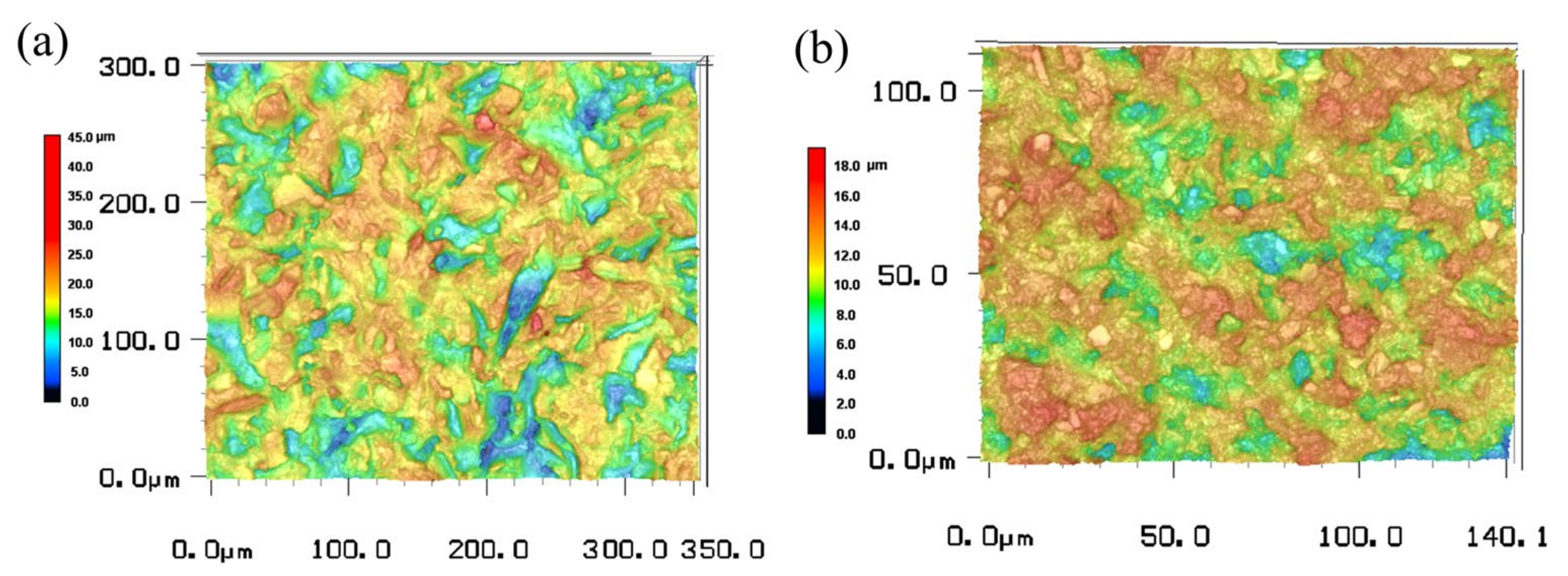
5.1. Diamond Grinding Wheel Topography after Texturing

The curve between the actual and ideal section profile was compared in Figure 9, and the profile error was analyzed. The measured values on the textured grinding wheels are in reasonably good agreement with the target values. The profile error of the metal-bonded and resin-bonded diamond wheels were 15.45 μm and 9.62 μm, respectively. The maximum profile error in the metal-bonded diamond wheel occurred near the middle of the sinusoidal contour, mainly caused by the increased water pressure, and a more abrasive flow rate increased the wheel material removal at the bottom of the sinusoidal profile. The profile error of the grinding wheel is also connected to the effect of the particles’ secondary impact, and the errors are confined to the allowable range. Two micro-textured grinding wheels and their corresponding microscopic morphology measurements are indicated in Figure 10. It can be seen from the figure that the bond material on the wheel surface was removed by MAWJ, leading to the emergence of a large proportion of abrasive grains with a certain protrusion height. It can be concluded that the texturing method, which uses MAWJ, obtains the desired textured-wheel profile and improves grinding performance. Comparing the results of two grinding wheels, it is proven that the resin-bonded diamond wheel has higher accuracy than the metal-bonded diamond wheels.

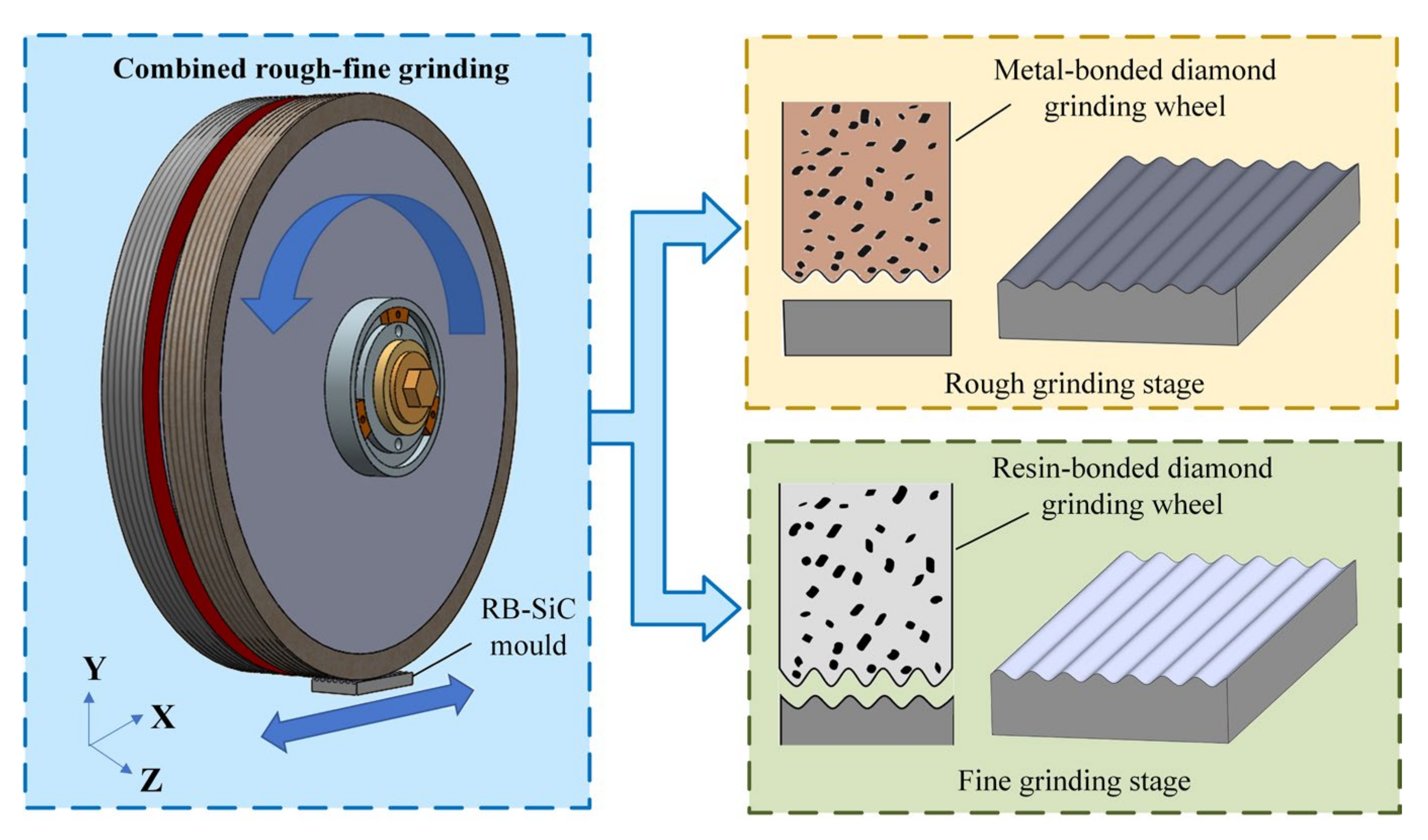
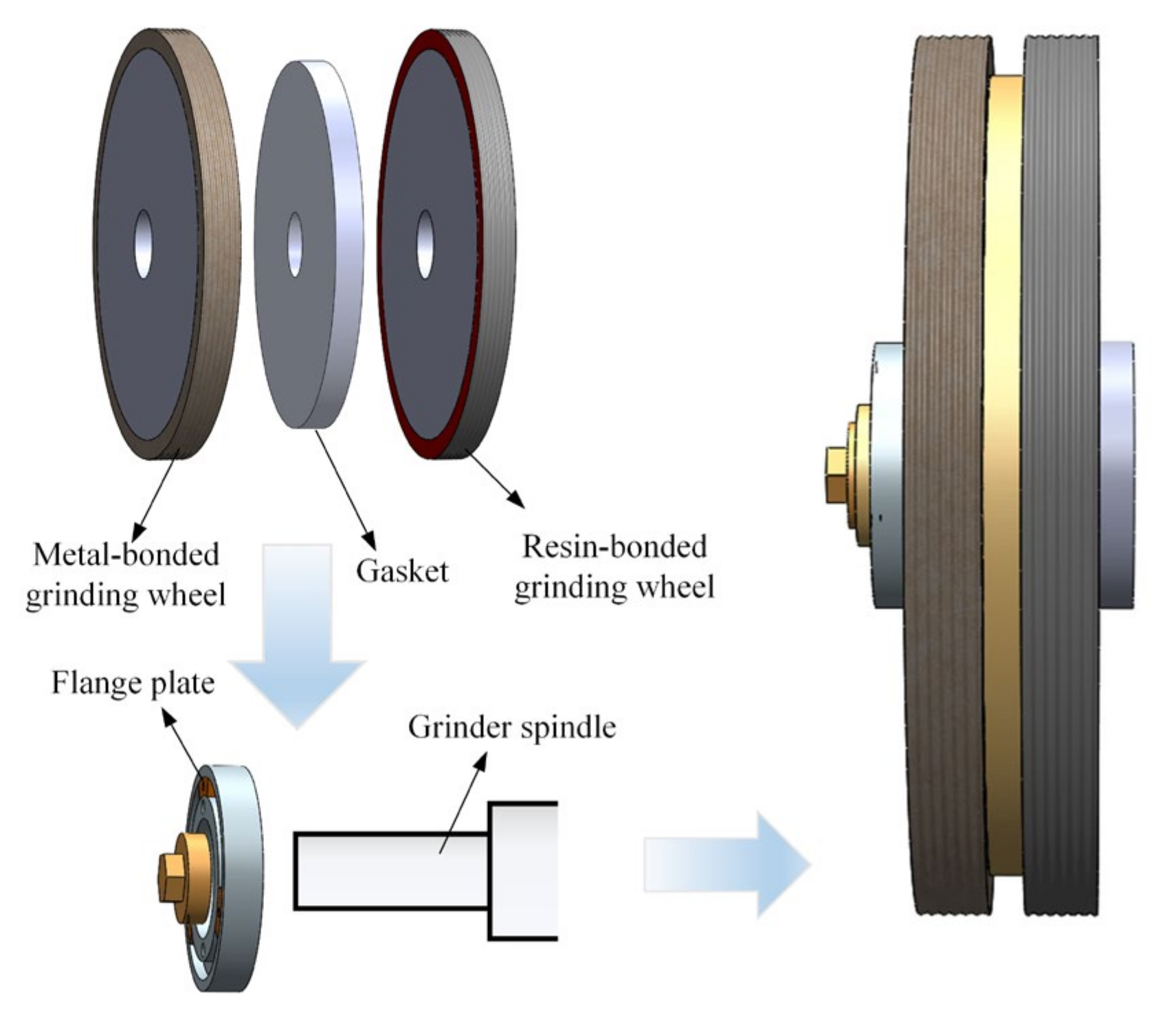
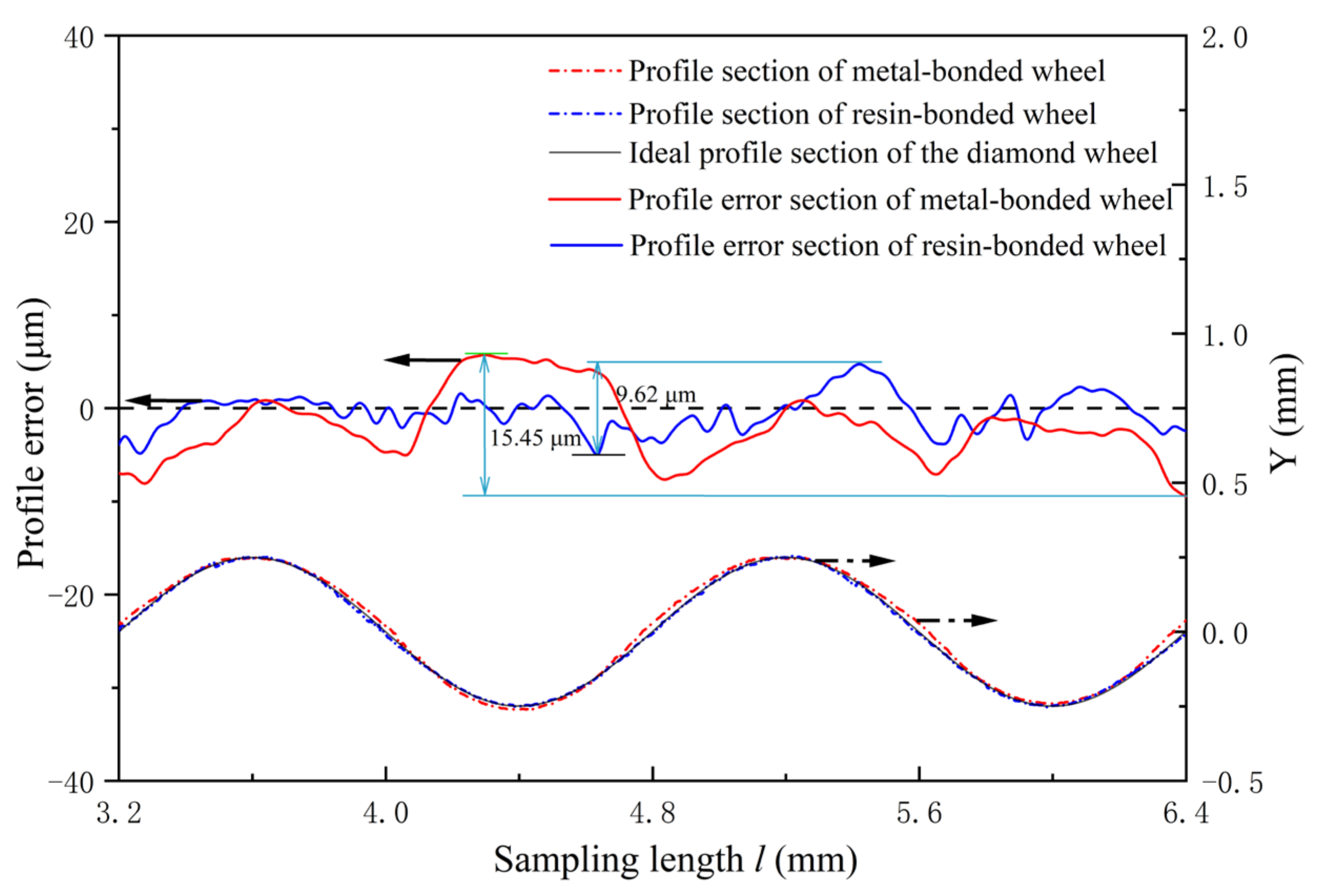
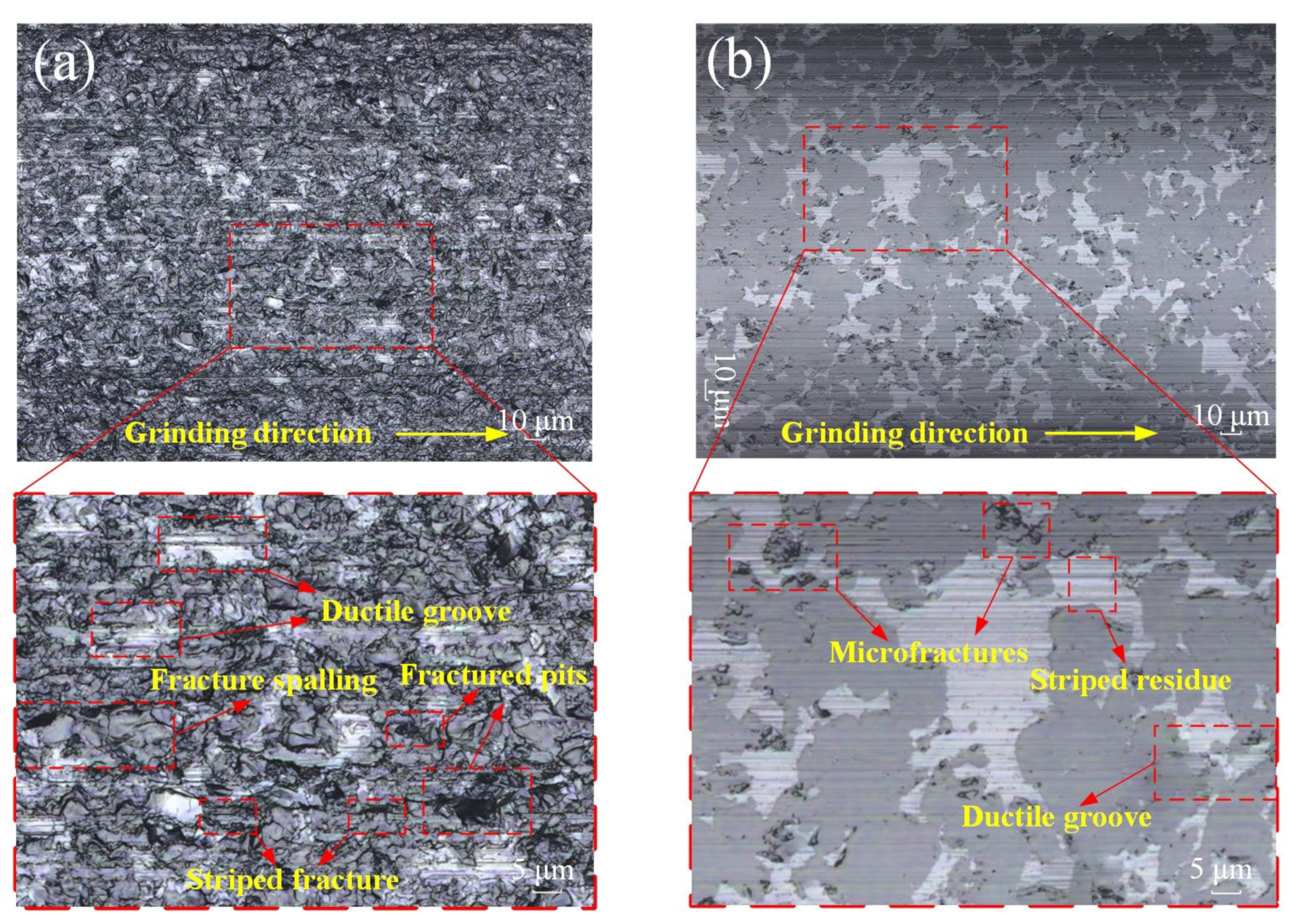
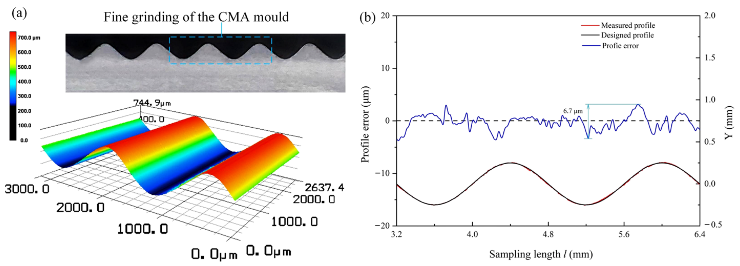
5.2. Combined Rough–Fine Grinding of CMA Moulds

Figure 11a shows the topography of the CMA mould after rough grinding. It presents that subsurface microcracks dominated material removal in the rough grinding process. The rough grinding stage observed several micro-cracks, fracture spalling, and fractured pits in the SiC phase. Some fractured pits are connected end-to-end to form a continuous fracture zone, caused by the increased feed rate and large depth of the cut. Figure 11b illustrates the appearance of the CMA mould after fine grinding. The machined surface is mainly composed of ductile grooves and striped residue. Most of the grooves are distributed on the grinding surface along the grinding direction, while a small amount of flake fragmentation and large pits exist in the SiC phase. The striped fracture and ductile grinding surface are significantly improved because of the large wheel rotational feed rate and small cut depth, resulting in the decrease in the maximum undeformed chip thickness. The material removal mechanism involved plastic deformation, brittle fracture, and brittle plastic mixing. To further improve the surface quality of CMA moulds, it is necessary to polish them again to eliminate the broken layer.
Figure 12 shows LSM photos of the CMA mould and the fine-grinding profile accuracy of the CMA mould. The excellent surface topography of the CMA mould was machined using a rough–fine grinding strategy. After grinding, the topography of the formed microstructure array was uniform and smooth. From the result, the P.V. value of the sampling length is 6.7 μm, the error value of the sampling length near the middle of the sinusoidal contour, corresponding to the profile error curve of the resin-bonded diamond wheel. Hence, the precision of the CMA profile is highly dependent on the precision of the grinding wheel profile. The profile error of the grinding wheel is directly recorded on the CMA’s surface.

6. Conclusions

This study proposed a combined rough and fine grinding process to achieve a highly efficient precision grinding of the RB-SiC mould. The conclusions drawn are as follows:
(1) Based on the homogenization principle of CMA and the optical phenomenon of reflection and refraction analyzed by ray-tracing software ZEMAX® for the design and simulation of optical arrays, the flat-top coefficient of light intensity that can satisfy the most excimer laser applications is calculated to be 0.80. Moreover, the light intensity difference is within 12%, and the light intensity error is below 6%.
(2) The diamond grinding wheels are textured based on the principle of MAWJ machining. The mathematical modelling of the unit removal function is established, and the simulated results show that the removal function is cosine distributed with high stability. The texturing method, which uses MAWJ, obtained the desired textured-wheel profile and improved grinding performance.
(3) By using MAWJ-textured diamond wheels, the profile error (in PV) of the CMA moulds can be further reduced to 6.7 μm using the combined rough–fine strategy grinding process.

Author Contributions

Conceptualization, F.S.; data curation, F.S.; methodology, Z.Z.; validation, Z.Z.; writing—review and editing, F.S., H.Y. and H.X.; supervision, Y.Z. and P.Y.; project administration, M.G. All authors have read and agreed to the published version of the manuscript.

Funding

This research was financially supported by Shandong Provincial Natural Science Foundation (No. ZR2021QE244), the Doctoral Research Fund of Shandong Jianzhu University (Grant No. X21032Z), the National Natural Science Foundation of China (52005301, 51975339, 51875321), and the National Undergraduate Training Program for Innovation and Entrepreneurship of Shandong Jianzhu University (202110430001).

Institutional Review Board Statement

Not applicable.

Informed Consent Statement

Not applicable.

Data Availability Statement

Not applicable.

Conflicts of Interest

The authors declare that they have no known competing financial interest or personal relationship that could have appeared to influence the work reported in this paper.

References

  1. Jin, Y.; Hassan, A.; Jiang, Y. Freeform microlens array homogenizer for excimer laser beam shaping. Opt. Express 2016, 24, 24846–24858. [Google Scholar] [CrossRef] [PubMed]
  2. Shaoulov, V.; Martins, R.; Rolland, J.P. Compact microlenslet-array-based magnifier. Opt. Lett. 2004, 29, 709–711. [Google Scholar] [CrossRef]
  3. Babadi, S.; Ramirez-Iniguez, R.; Boutaleb, T.; Mallick, T. Performance comparison of a freeform lens and a CDTIRO when combined with an LED. IEEE Photonics J. 2017, 9, 1–8. [Google Scholar] [CrossRef]
  4. Mashaal, H.; Feuermann, D.; Gordon, J.M. Aplanatic lenses revisited: The full landscape. Appl. Opt. 2016, 55, 2537–2542. [Google Scholar] [CrossRef] [PubMed]
  5. Qu, S.; Yao, P.; Gong, Y.; Yang, Y.; Chu, D.; Zhu, Q. Modelling and grinding characteristics of unidirectional C-SiCs. Ceram. Int. 2022, 48, 8314–8324. [Google Scholar] [CrossRef]
  6. Zhang, L.; Liu, W. Precision glass molding: Toward an optimal fabrication of optical lenses. Front. Mech. Eng. 2017, 12, 3–17. [Google Scholar] [CrossRef] [Green Version]
  7. Chang, C.; Chu, J. Innovative design of reel-to-reel hot embossing system for production of plastic microlens array films. Int. J. Adv. Manuf. Technol. 2017, 89, 2411–2420. [Google Scholar] [CrossRef]
  8. Cook, K.; Mcgeorge, R.; Kar, A.K.; Taghizadeh, M.R.; Lamb, R.A. Coherent array of white-light continuum filaments produced by diffractive microlenses. Appl. Phys. Lett. 2005, 86, 021105. [Google Scholar] [CrossRef]
  9. Surdo, S.; Diaspro, A.; Duocastella, M. Microlens fabrication by replica molding of frozen laser-printed droplets. Appl. Surf. Sci. 2017, 418, 554–558. [Google Scholar] [CrossRef]
  10. Marques-Hueso, J.; Sanchis, L.; Martínez-Pastor, J.P. Properties of silicon integrated photonic lenses: Bandwidth, chromatic aberration, and polarization dependence. Opt. Eng. 2013, 52, 91710. [Google Scholar] [CrossRef]
  11. Sohn, I.B.; Choi, H.K.; Noh, Y.C.; Kim, J.; Ahsan, M.S. Laser assisted fabrication of micro-lens array and characterization of their beam shaping property. Appl. Surf. Sci. 2019, 479, 375–385. [Google Scholar] [CrossRef]
  12. Luo, Z.; Yin, K.; Dong, X.; Duan, J. Fabrication of parabolic cylindrical microlens array by shaped femtosecond laser. Opt. Mater. 2018, 78, 465–470. [Google Scholar] [CrossRef]
  13. Gyongy, I.; Davies, A.; Gallinet, B.; Dutton, N.; Dalgarno, P.A. Cylindrical microlensing for enhanced collection efficiency of small pixel SPAD arrays in single-molecule localization microscopy. Opt. Express 2018, 26, 2280–2291. [Google Scholar] [CrossRef] [PubMed] [Green Version]
  14. Albero, J.; Nieradko, L.; Gorecki, C.; Ottevaere, H.; Passilly, N. Fabrication of spherical microlenses by a combination of isotropic wet etching of silicon and molding techniques. Opt. Express 2009, 17, 6283–6292. [Google Scholar] [CrossRef] [PubMed]
  15. Huang, S.; Li, M.; Shen, L.; Qiu, J.; Zhou, Y. Fabrication of high quality aspheric microlens array by dose-modulated lithography and surface thermal reflow. Opt. Laser Technol. 2018, 100, 298–303. [Google Scholar] [CrossRef]
  16. Hu, Y.; Zhu, X.; Li, H.; Qian, L.; Lan, H. Fabrication of large-area cylindrical microlens array based on electric-field-driven jet printing. Microsyst.Technol. 2019, 25, 4495–4503. [Google Scholar] [CrossRef]
  17. Zhang, X.; Liu, K.; Shan, X.; Liu, Y. Roll-to-roll embossing of optical linear Fresnel lens polymer film for solar concentration. Opt. Express 2014, 22, A1835–A1842. [Google Scholar] [CrossRef]
  18. Zhou, T.; Liu, X.; Liang, Z.; Liu, Y.; Xie, J.; Wang, X. Recent advancements in optical microstructure fabrication through glass molding process. Front. Mech. Eng. 2017, 12, 46–65. [Google Scholar] [CrossRef] [Green Version]
  19. Chen, S.; Lin, S. Development of an extremely thin grinding-tool for grinding microgrooves in optical glass. J. Mater. Process. Technol. 2011, 211, 1581–1589. [Google Scholar] [CrossRef]
  20. Denkena, B.; Köhler, J.; Wang, B. Manufacturing of functional riblet structures by profile grinding. CIRP J. Manuf. Sci. Technol. 2010, 3, 14–26. [Google Scholar] [CrossRef]
  21. Yao, P.; Wei, W.; Huang, C.Z.; Wang, J.; Zhu, H.T.; Zhang, Z.Y. High efficiency abrasive water-jet dressing of diamond grinding wheel. Adv. Mater. Res. 2014, 1017, 243–248. [Google Scholar] [CrossRef]
  22. Shen, J.Y.; Xu, X.P.; Lin, B.; Xu, Y.S. Lap-Grinding of Al2O3 ceramics assisted by water-jet dressing metal bond diamond wheel. Key Eng. Mater. 2001, 202–203, 171–176. [Google Scholar] [CrossRef]
  23. Zhang, Z.; Yao, P.; Zhang, Z.; Xue, D.; Wang, C.; Huang, C.; Zhu, H. A novel technique for dressing metal-bonded diamond grinding wheel with abrasive water-jet and touch truing. Int. J. Adv. Manuf. Technol. 2017, 93, 3063–3073. [Google Scholar] [CrossRef]
  24. Li, H.; Zhang, W.; Yu, G. Study of weighted space deconvolution algorithm in computer controlled optical surfacing formation. Chin. Opt. Lett. 2009, 7, 627–631. [Google Scholar]
  25. Luo, X.; Zheng, L.G.; Zhang, X.J. Finite element analysis simulation and experimental verification of the stressed lap’s deformation accuracy. Appl. Opt. 2011, 50, 782–787. [Google Scholar] [CrossRef] [PubMed]
  26. Deng, H.; Ueda, M.; Yamamura, K. Characterization of 4H-SiC (0001) surface processed by plasma-assisted polishing. Int. J. Adv. Manuf. Technol. 2014, 72, 1–7. [Google Scholar] [CrossRef]
  27. Li, F.; Xie, X.; Tie, G.; Hu, H.; Zhou, L. Figuring process of potassium dihydrogen phosphate crystal using ion beam figuring technology. Appl. Opt. 2017, 56, 7130–7137. [Google Scholar] [CrossRef]
  28. Johnson, M.E.; Voigtman, E. Temporal and spectral characteristics of the output of an excimer laser. Appl. Spectrosc. 1990, 44, 958–961. [Google Scholar] [CrossRef]
  29. Zhang, L.; Zhao, Q.; Fan, C. Dwell time algorithm in deterministicpolishing of free-form surface based oncontinuous tool influence function. Appl. Opt. 2021, 60, 2704–2715. [Google Scholar] [CrossRef]
  30. Zhang, Z.; Yao, P.; Huang, C.; Wang, J.; Xue, D.; Deng, W.; Zhang, Z. Investigation and modeling of microgrooves generated on diamond grinding wheel by abrasive water-jet based on Box—Behnken experimental design. Int. J. Adv. Manuf. Technol. 2019, 100, 321–332. [Google Scholar] [CrossRef]
Figure 1. Optical schematic illustration of optical CMA homogenizer.
Applsci 12 06893 g001
Figure 2. Simulated excimer laser beam profile: (a) Pseudocolor representation of the strength distribution on the detector; (b) the x-direction standardized strength distribution chart; and (c) the y-direction standardized strength distribution chart.
Applsci 12 06893 g002
Figure 3. Schematic diagram of the combined grinding process.
Applsci 12 06893 g003
Figure 4. Configuration of a grinding wheel clamp for combined grinding.
Applsci 12 06893 g004
Figure 5. Schematic diagram of the dwell time algorithm.
Applsci 12 06893 g005
Figure 6. Velocity field inside and outside the nozzle.
Applsci 12 06893 g006
Figure 7. Micro-abrasive water jet in situ texturing experimental system.
Applsci 12 06893 g007
Figure 8. Experimental setup for combined grinding of CMA moulds.
Applsci 12 06893 g008
Figure 9. Analysis of the profile of diamond wheel after texturing.
Applsci 12 06893 g009
Figure 10. Microscopic morphology after texturing of (a) the metal-bonded grinding wheel and (b) the resin-bonded grinding wheel.
Applsci 12 06893 g010
Figure 11. Surface topographies of the CMA mould after (a) rough grinding and (b) fine grinding.
Applsci 12 06893 g011
Figure 12. (a) Laser Confocal Microscope (LSM) photos of the CMA mould; (b) The fine-grinding profile accuracy of the CMA mould.
Applsci 12 06893 g012
Table 1. The comparison of different manufacturing techniques for microlenses.
TechniqueAdvantagesDisadvantagesReferences
Glass mouldingLow cost, high repeatabilityHigh-temperature requirements[5,6]
Reactive ion etchingGood surface properties, high repeatability in the maskless processHigh equipment costs and difficulty in processing due to the need for a mask[7,8]
PhotolithographyProduces microlenses over large areasHigh cost due to need for master mould[9,10]
Femtosecond direct writingHigh accuracy and resolutionHigh cost due to expensive femtosecond laser[11,12]
Table 2. Parameters of CMAs and imaging system.
Lens and Imaging SystemParameters
Shape of lensSinusoidal
Amplitude/mm0.25
Period/mm0.8
MaterialK-PG325
Thickness of lens/mm0.8
Table 3. Micro abrasive water jet texturing parameters.
Grinding WheelWater Pressure (MPa)Standoff
Distance
(r/min)
Wheel Speed
(r/min)
Abrasive Flowrate
(g/min)
Metal-bonded grinding wheels30.001.0060.0020.00
Resin-bonded grinding wheels20.001.0060.001.20
Table 4. Rough grinding process parameters.
ParametersWheel Speed
(m/s)
Feed Rate (m/s)Depth of Cut (μm)Grinding Coolant
Value200.1755% water-based grinding fluid SC25AC
Table 5. Fine grinding process parameters.
ParametersWheel Speed
(m/s)
Feed Rate (m/s)Depth of Cut (μm)Grinding Coolant
Value300.0570.505% water-based grinding fluid SC25AC
Publisher’s Note: MDPI stays neutral with regard to jurisdictional claims in published maps and institutional affiliations.

