Article

Thermodynamic Analysis of In-Cylinder Steam Assist Technology within an Internal Combustion Engine

1
School of Automotive Studies, Tongji University, Shanghai 201804, China
2
State Key Laboratory of Mechanical Transmission, Chongqing University, Chongqing 400044, China
3
College of Mechanical and Vehicle Engineering, Chongqing University, Chongqing 400044, China
*
Author to whom correspondence should be addressed.
Appl. Sci. 2022, 12(13), 6818; https://doi.org/10.3390/app12136818
Submission received: 21 May 2022 / Revised: 1 July 2022 / Accepted: 4 July 2022 / Published: 5 July 2022
(This article belongs to the Topic Energy Saving and Energy Efficiency Technologies)

Abstract

:
For the requirements of rigorous CO2 and emissions regulations, steam assist technology is an effective method for thermal efficiency enhancement. However, few studies apply steam assist technology in modern internal combustion engines. Stimulated by its application prospects, the present study proposes a thermodynamic analysis on the in-cylinder steam assist technology. An ideal engine thermodynamic model combined with a heat exchanger model is established. Some critical parameters, such as steam injection temperature, injection pressure and intake pressure, are calculated under different steam injection masses. The thermal efficiency boundaries are also analyzed at different compression ratios to investigate the maximum potential thermal efficiency of the technology. The analysis shows that the in-cylinder steam-assisted cycle has the potential to increase engine efficiency considerably. Both steam injection temperature and injection mass improve thermal efficiency. Considering the energy trade-off relationship between steam and exhaust gas, the maximum gain in thermal efficiency achieved with the cycle is 14.5% at a compression ratio of 10. The optimum thermal efficiency can be increased from 54.0% to 59.71% by increasing the compression ratio from 10 to 16. The mechanism lies in the specific heat ratio enhancement from a thermodynamic perspective, which improves the thermal-heat conversion efficiency. The results provide considerable guidance for the future experimental and numerical studies of in-cylinder steam assist technology into modern engines.

1. Introduction

With the rapid pace of industrialization, internal combustion engines (ICEs) contribute greatly to human mobility and cargo transportation, improving people’s living standards conspicuously. However, the increasing concerns about greenhouse gas (GHG) emissions from ICEs are drawing much attention from governments and societies regarding to environment and energy problems, which forces the government to tighten fuel consumption and emissions regulations [1,2]. The fuel consumption is going to be confined to below the threshold of 4 L/100 km in 2025 according to China’s Phase V Corporate Average Fuel Consumption (CAFC) regulation [3]. As a complementary for a laboratory test, the Real Driving Emissions (RDE) test requires the ICE’s manufacturers to make a significant leap in emissions control over on-road conditions [4]. Thus, research on energy-saving and emissions-reducing technologies is necessary for the sustainable development of the ICE industry [5]. Recently, automotive powertrain development is transitioning away from ICE vehicles (ICEVs) to fuel cell vehicles (FCVs), battery electric vehicles (BEVs), hybrid electric vehicles (HEVs), and so on. Despite these challenges, the electrification of ICEs provides a feasible technical solution in optimizing engine operation range, therefore providing an opportunity to maximize its benefits [6]. Obviously, ICEs will still play a vital role in the automotive industry for at least several decades. Therefore, the long-term aim of engine researchers and manufacturers has been simultaneously focused on lower fuel consumption and emissions.
For the requirements of rigorous CO2 and emissions regulations, feasible solutions are being developed for energy conservation and emission reduction, including high ignition energy, cooled EGR [7], high tumble ratio, long-stroke, ultra-lean combustion [8,9], homogeneous charge compression ignition, over-expansion cycles (Miller and Atkinson) [10], ultra high-pressure injection [11] and so on. Among them, in-cylinder steam assist technology has been proposed in recent years. Based on the Internal Combustion Engine 4.0 proposed by the AVL Co. Ltd., (Graz, Austria) water injection and steam processes are essential to achieving thermal efficiencies above 50% [12]. Developed from water injection technology, in-cylinder steam assist technology recovers thermal energy from engine coolant and exhaust gases and optimizes the combustion and emission features of prototype engines. In addition, the problems of metal corrosion and lubricating oil emulsification caused by liquid water slipping through the cylinder walls can be avoided [13,14].
The steam assist technology has drawn much attention in recent years, and various forms of it have been realized. Parlak and Gonca et al. [15,16,17,18,19] conducted a series of investigations into the steam assist technology, in which steam was introduced into the combustion chamber by an intake manifold injector. The results demonstrate a specific fuel consumption drop of >5.0% and a power output increase of 0.6–2.8%. When the steam is introduced into a cylinder during the compression stroke, the power output increases by 5.9% to 7.8% at full load, while the injection timing moves from −120° to −30° CA ATDC [20]. The steam assist technology was also applied to the control and optimization of the elevated combustion temperature in the engine with an oxy-fuel combustion mode [21,22,23,24]. Wu et al. [25,26,27,28,29] conducted theoretical and experimental studies on the internal combustion Rankine cycle to achieve high thermal efficiency and a low emission powertrain. The results show that the thermal efficiency of a spark ignition engine was improved by 26.1% with the help of a 160 °C water injection. Li et al. [30] evaluated steam injection at the power stroke in a natural gas engine. Advancing steam injection timing reduced the brake-specific fuel consumption, with reductions of 3.9–5.2% obtained over different speeds at 50° CA ATDC. The concept of a six-stroke internal combustion engine cycle was proposed by Conklin and Szybist [31]. This concept mainly modifies the current four-stroke engine cycle, but with two water injection and expansion strokes added to improve fuel economy and power output. The experiment conducted by Arabaci et al. [32] shows that the specific fuel consumption reduced by 9%, and brake power improved by 10% at full load (2750 r/min) with stoichiometric AFR. Fu et al. [33] coupled the conventional Otto or diesel cycle with a steam-expansion cycle in an ICE using an open steam power cycle. In this cycle, three cylinders are used for ignition, and a fourth is used for steam expansion. Calculations indicate that thermal efficiency is enhanced by 6.3% at the maximum engine speed (6000 r/min). Zhao et al. [34,35] combined steam injection with turbo-compounding, demonstrating fuel economy gains of 6.0–11.2% in a turbocharged diesel engine at different speeds. Zhu et al. [36,37] also reported that the matching attribute of a turbocharging system with an engine could also be enhanced by pre-turbine steam injection, which improves fuel economy by about 5.9% at full load when combined with the Miller cycle.
Despite the research reviewed above, it should be noted that the mechanical structure of a six-stroke engine is complex to implementation and maintenance, and the oxy-fuel combustion mode of ICRC limits its application and industrialization. Although intake port and pre-turbine steam injection enhanced thermal efficiency, they decreased engine charge efficiency, resulting in a limitation of efficiency enhancement ability. The steam assist technology shows potential for ICE implementation because of its high thermal efficiency, low fuel consumption, compact size and flexible features. However, few studies apply steam assist technology in modern gasoline engines. Stimulated by its application prospects, this work provides a thermodynamic study on the feasibility of an in-cylinder steam-assisted cycle in a spark ignition engine, which provides the theoretical basis and boundaries for forthcoming experimental study.
In the following sections, a theoretical model is established for an in-cylinder steam-assisted cycle. Some critical parameters, such as injection temperature, injection pressure and intake pressure, are discussed for various injection masses. The thermal efficiency boundaries of this technology are also analyzed at different compression ratios to investigate its maximum potential thermal efficiency. The results provide comprehensive information for the industrial application of the in-cylinder steam assist technology.

2. Methodology

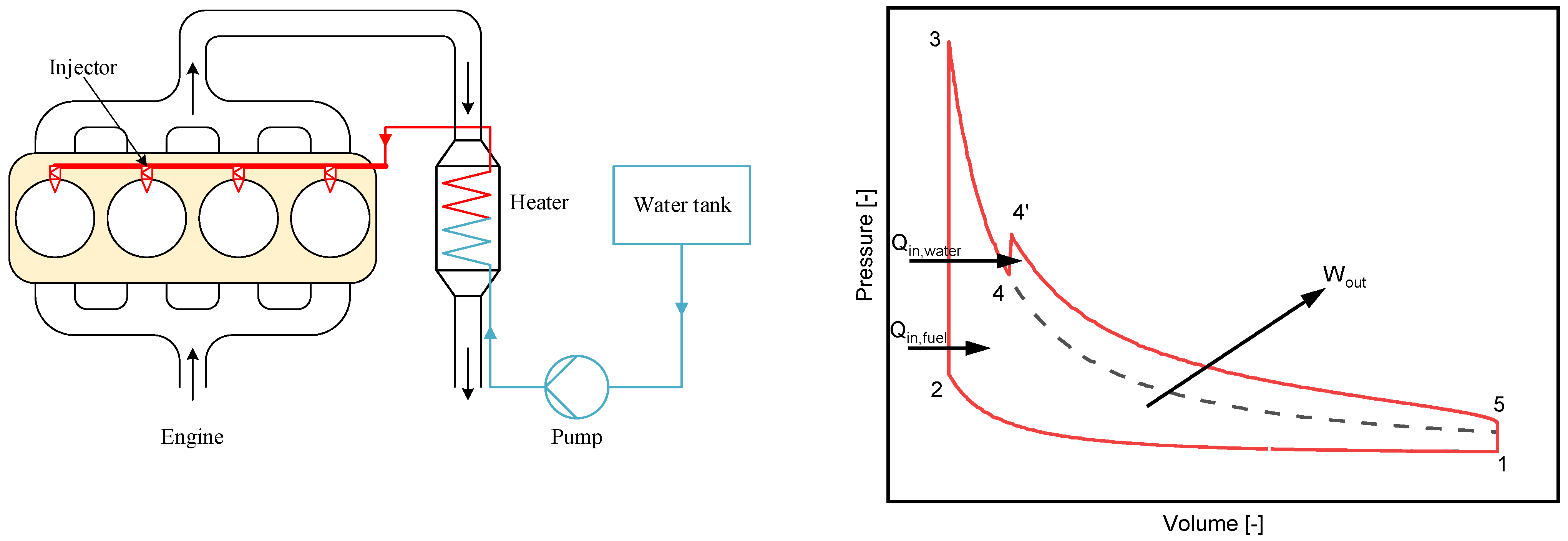
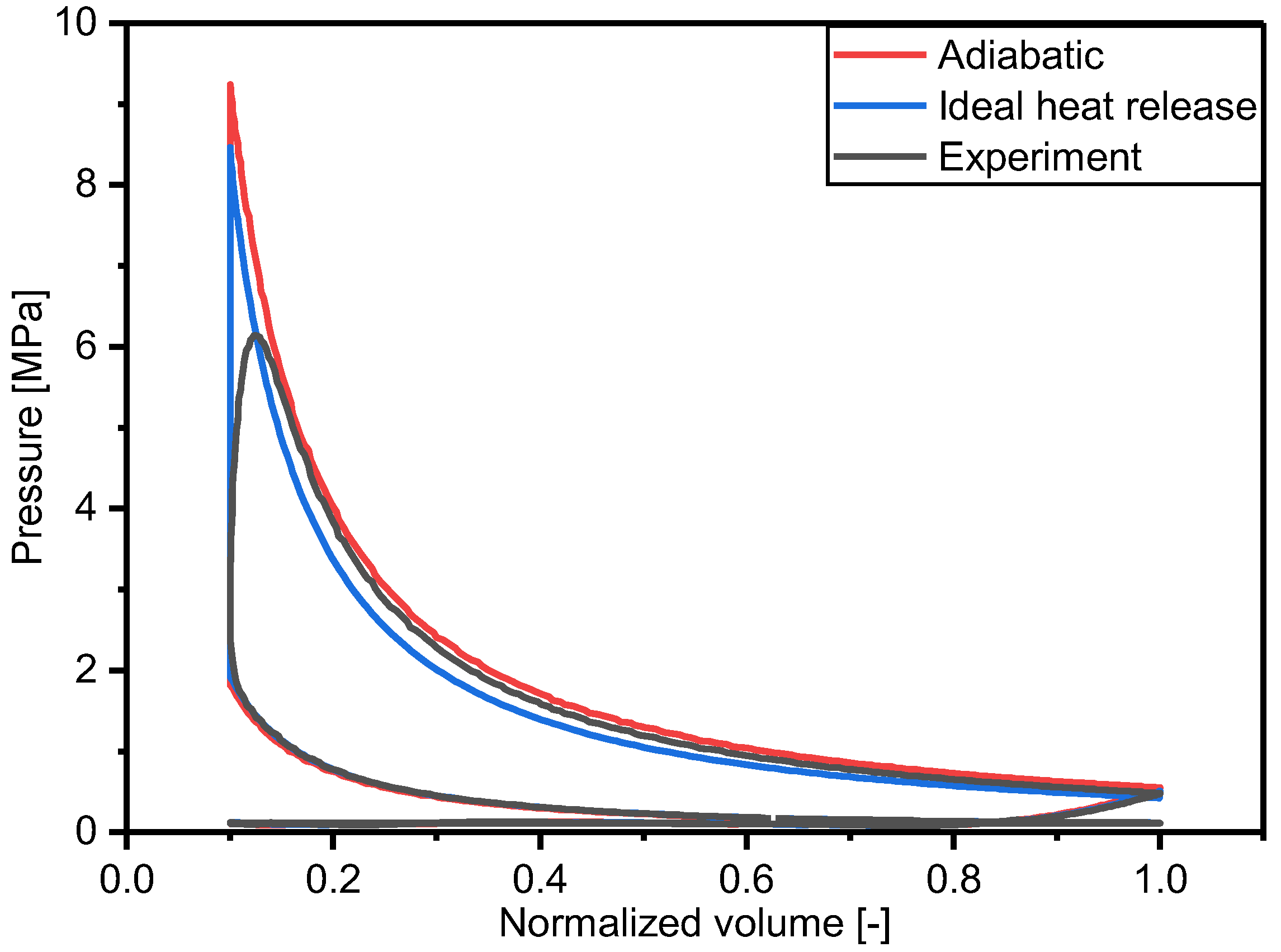
2.1. Thermodynamic Model and Validation

A schematic of the in-cylinder steam-assisted cycle and its thermodynamic process are shown in Figure 1. Some assumptions for the thermodynamic cycle process are given to simplify the computation. The compression and expansion strokes are assumed to be adiabatic processes. Compared to conventional gasoline engine, high-temperature and high-pressure water is directly injected into the combustion, which absorbs combustion heat and generates high-temperature and high-pressure steam instantly. This leads to an enhancement in in-cylinder pressure, which leads to higher compression work and thermal efficiency. As shown in previous study, injected steam evaporates immediately as it is injected into the combustion chamber at the end of compression [33]. Therefore, the effect of in-cylinder steam evaporation on the combustion process can be ignored for the theoretical thermodynamic analysis [26,34].
The established theoretical in-cylinder steam-assisted cycle is a closed system [26,28]. According to the first law of thermodynamics, its energy equation can be expressed as:
δ U = δ Q + δ W
where U is internal energy, Q is thermal energy, and W is work.
First, the thermal state for the Point 1 was calculated by the general gas equation:
p 1 V 1 = m R T 1
Then, assuming that the compression stroke of the proposed cycle is adiabatic in a closed system, the mixture is adiabatic compressed from Point 1 to Point 2 with a specific compression ratio:
V 2 = V 1 ε ,   s 2 = s 1
where ε is the compression ratio, and s is the specific entropy. Then, the energy equation for the compression stroke is:
W 12 = m T 1 T 2 c v d T
Here, W 12 is the work in the compression stroke, m is the intake charge mass, T is temperature, and c v is the specific heat at constant volume.
Second, fuel burns within a constant volume, and its energy is released instantly, and the temperature after combustion T 3 is calculated by the element potential method. Accompanied by the combustion process, high-temperature steam is introduced into the combustion chamber by an injector in the expansion stroke. The energy change during the steam injection process can be described as:
m w h w = T 4 T 4 ( m + m w ) c v d T
where m w is the injected steam mass and h w is its specific enthalpy.
Except for the energy conversion, the working medium for the closed system increases after steam injection. Then, the expansion stroke of exhaust and high-temperature vapour is also assumed to be adiabatic in the closed system. The change in energy can be expressed as:
W 35 = T 3 T 4 m c v d T + T 4 T 4 ( m + m w ) c v d T + ( m + m w ) T 4 T 5 c v d T
Here, W 35 is the work in the expansion stroke.
In order to maintain the steam in a fluid state, it is pressurized to >10 MPa before the heat exchanger. The energy of pump consumption can be written as:
W pump = m w p initial p injection v d p / η pump
where W pump is the work consumed by the pump, v is specific volume, p is injection pressure, and η pump is the pump’s efficiency.
Therefore, the indicated work output and thermal efficiency for each cycle would be:
W indicated = W 12 + W 35 W pump
And
η indicated = W indicated / ( L H V fuel m fuel )
where η indicated is the indicated thermal efficiency, L H V fuel is the low heating value of the fuel, which is assumed as 47.67 kJ/kg for the calculation, and m fuel is the mass of fuel consumed per cycle.
Based on this thermodynamic model, the thermodynamic state parameters of the constant-volume heating and adiabatic processes are acquired using the STANJAN software of Reynolds, which is an interactive computer program for chemical equilibrium analysis using the element potential method. Then, the thermodynamic state parameters after steam injection are acquired by a self-established MATLAB program.
In addition to the thermodynamic model and its assumptions, the initial conditions and constraints are also critical parameters affecting the cycle’s thermal efficiency and are listed in Table 1. The engine utilized in this theoretical model is a spark-ignition engine fuelled with iso-octane (i-C8H18) at the stoichiometric ratio (i.e., a conventional gasoline engine). The calculation is an ideal theoretical model, and the heat transfer through cylinders was not included for a maximum thermal efficiency of steam assist cycle. To be specific, the model simplifies the cycle as an adiabatic process with ideal heat release, and steam is introduced into the combustion chambers at TDC and evaporates instantaneously. The assumption of the instantaneous injection, vaporization, and mixing process are not physically realistic, but it is valid to estimate the upper bound on both the potential work output and thermal efficiency of this engine cycle. The combustion process focuses on the thermodynamic heat release, completed at the TDC combustion instantaneously. Thus, the combustion duration is negligible. The engine geometry, intake composition and initial temperature are set based on the parameters of the original spark-ignition engine, shown in Table 2. The initial cylinder pressure is set at the end of the intake stroke (0.1–0.3 MPa), which includes the load range of normally aspirated and turbocharged engines at various speeds. To investigate the gains of the compression ratio under different steam injection strategies, the compression ratio is varied from 10 to 16. To reveal the impacts of in-cylinder steam injection strategies on the thermal efficiency, the steam injection temperature range is 300–600 K. The steam injection pressure also varies from 20 to 50 MPa at a steam injection mass of 0–0.4 g. Finally, the thermodynamic model validates with the experimental pressure traces, as shown in Figure 2. In the validated experiment, steam was injected into the cylinder at 473 K and 15 MPa, and the coolant temperature is 85 °C. The ideal heat release case considered the heat transfer loss and its heat transfer coefficient through cylinders was calculated based on the Woschni model.

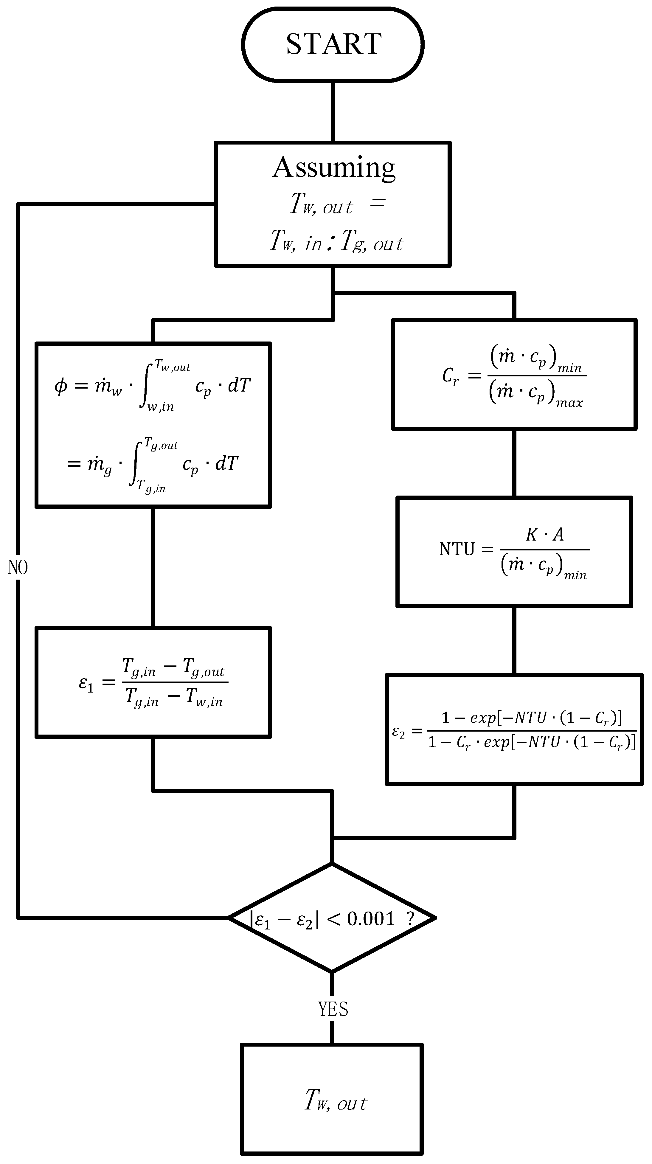
2.2. Heat Exchanger Design

In the proposed in-cylinder steam-assisted cycle, to achieve ultra-high thermal efficiency, the energy used to heat the steam injection is provided by exhaust gases via a specially designed heat exchanger. It is clear that the effectiveness of the heat exchanger is essential to the optimization of the system’s thermal efficiency. In practical operations with this cycle, steam is pressurized in a pump to maintain its liquid state while being heated by an exhaust in a heat exchanger; therefore, the effectiveness of the heat exchanger determines the injected steam’s upper-temperature limit.
Considering the requirements of construction, cost and the working environment, tubular heat exchangers are the best choice. The parameters of such a heat exchanger are designed and discussed in this section, based on an ideal thermodynamic analysis. Table 3 presents the input parameters of the shell and tube heat exchanger used, which comprises one shell and tube pass. The engine speed is set to 5000 r/min. The exhaust mass flow rate and its temperature are computed from engine calculations conducted in STANJAN. The mass flow rate of injected steam is measured according to the fuel mass flow rate, and the inlet temperature is set to an ambient temperature of 298 K.
First, according to a heat transfer equation, the heat flux in a heat exchanger can be described as:
Φ = K A T m
where Φ is heat flux, K is the overall coefficient of heat transfer, A is the area of heat transfer, and T m is the logarithmic mean temperature difference (LMTD), where T m can be calculated as:
T m = ( T w , out T w , in ) ( T g , in T g , out ) ln ( T w , out T w , in ) ln ( T g , in T g , out )
According to the heat exchanger’s thermodynamic balance, the temperatures at the inlets and outlets can be calculated as:
ϕ = m ˙ w T w , in T w , out c p d T = m ˙ g T g , in T g , out c p d T
where the m ˙ is the mass flow rate and c p is the specific heat at constant pressure. Subscripts “g” and “w” indicate exhaust gas and water steam, respectively.
Next, a reasonable heat transfer coefficient K should be assumed, and the heat transfer area A can be determined. After that, the preliminary geometric parameters of the heater can be determined according to the area.
Second, the inside heat transfer coefficient of tubes h i are calculated by the Nusselt number   N u , Prandtl number   P r , and Reynolds number   R e , as follows:
N u = R e w 1 3 P r w 1 3 ( L d i ) 1 3 ( μ w μ wall ) 0.14
Then,
h i = N u k w d i / 4
where k is the fluid’s thermal conductivity, μ is the fluid’s dynamic viscosity, and subscript “wall” represents the tube wall.
Similarly, the outside heat transfer coefficient of tubes h o are computed by the Prandtl number and Reynolds number, as follows:
h o = 0.36 k g d e R e g 0.55 P r g 1 3 ( μ w μ wall ) 0.14
Here, the subscripts, “g”, “w” and “wall”, indicate the exhaust gas, water steam and tube wall, respectively. The equivalent diameter d e is calculated from the inner diameter d i , the outer diameter d o and the tube’s centre distance   P t .
d e = 4 P t 2 π d o 2 π d i 2
Thus, the calculated heat transfer coefficient K can be derived from the convective heat transfer coefficients of the shell and tube side, together with the heat conduction resistance of the tube wall, as follows:
K = 1 1 h o + d o 2 λ ln ( d i d o ) + 1 h i d o d i
where λ is the thermal conductivity of carbon steel.
Finally, the calculated heat transfer coefficient is verified with the assumed value. If the calculated value is greater than the assumed one, the parameters of the designed heat exchanger are reasonable. Table 4 displays the final designed parameters of the heat exchanger.

2.3. Boundary Definition and Verification

In the in-cylinder steam-assisted cycle, the effectiveness of the heat exchanger determines the upper-temperature limit of injected steam. Hence, the limitation on the injected steam’s temperature is verified in this section. In the heat exchanger analysis, the LMTD method can be considered when the fluid inlet and outlet temperatures are available or calculated based on the energy equations. However, if the LMTD temperature conditions are insufficient, the number of transfer units (NTU) or effectiveness method is an alternative approach to estimating the heat transfer rate. The effectiveness of a heat exchanger is defined as the ratio between the actual and theoretical heat transfer rate that can be obtained in an ideal counter-flow heat exchanger of infinite length. Therefore, the effectiveness is also equal to the ratio between the actual and maximum possible temperature difference and can be expressed as follows:
ε 1 = q q max = T g , in T g , out T g , in T w , in
Additionally, the effectiveness can be calculated by the heat capacity ratio and a dimensionless parameter, as follows:
ε 2 = 1 e x p [ N T U ( 1 C r ) ] 1 C r e x p [ N T U ( 1 C r ) ]
where the NTU is universally applied for heat exchanger analysis and can be expressed as:
N T U = K A ( m ˙ c p ) min
where the overall heat transfer coefficient K and heat exchanger area A are determined as in the previous section. Additionally, the heat capacity ratio C r is calculated as:
C r = ( m ˙ c p ) min ( m ˙ c p ) max
The calculation of outlet temperature is conducted in two steps. Figure 3 shows a flowchart that verifies the maximum injected steam temperature under a specific steam-to-air ratio. The first step is to assume an outlet steam temperature, which falls between the inlet steam temperature and outlet exhaust temperature. The second step is to calculate the difference between the two effectiveness methods mentioned above until the error is <0.001.

3. Results and Discussion

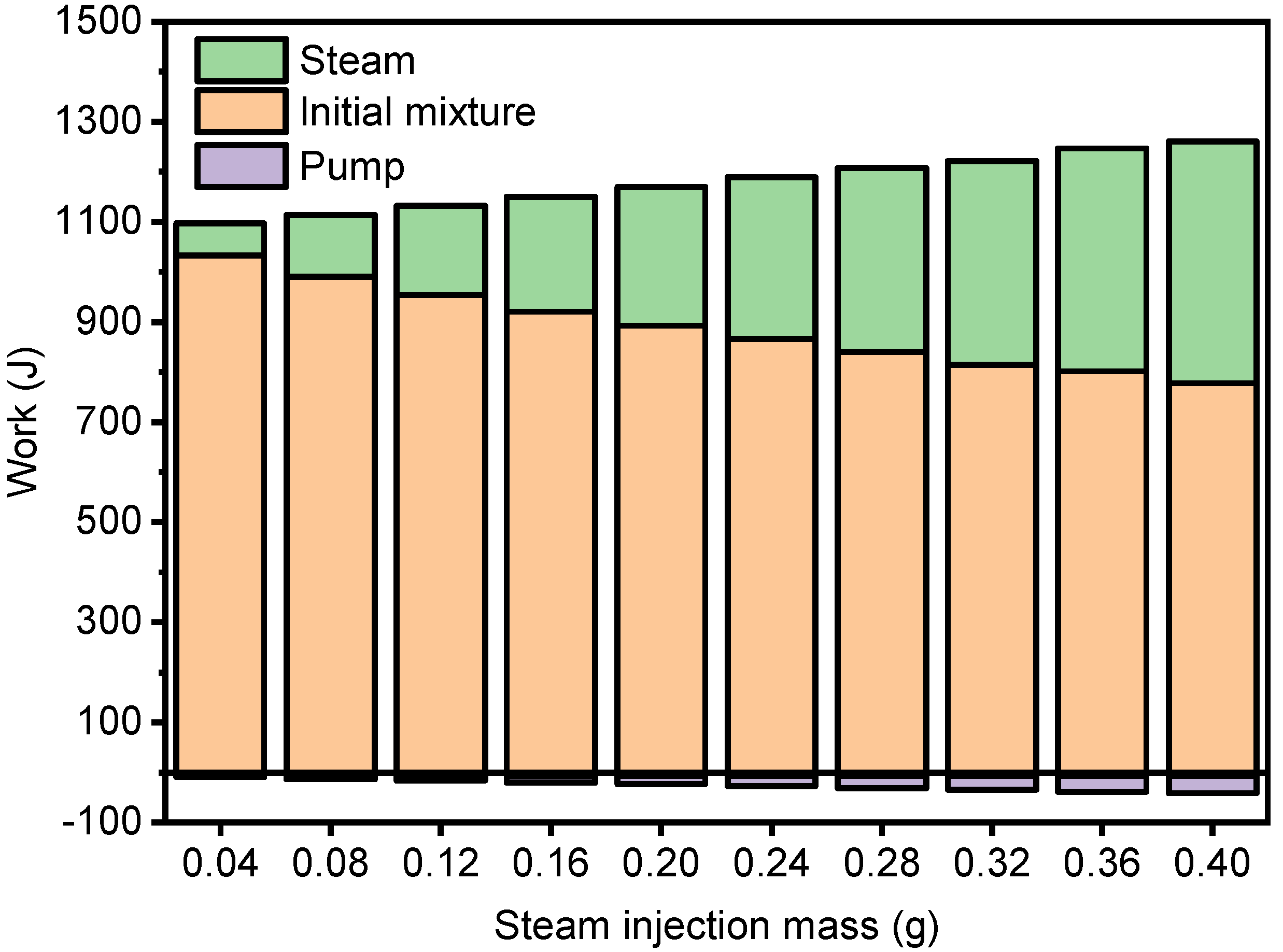
3.1. Effects of Injection Temperature and Mass on Cycle Performance

Before focusing on the in-cylinder steam-assisted cycle, the influence of steam injection parameters should be analyzed. Figure 4a presents the relationship between in-cylinder temperature at TDC and steam injection mass under different steam injection temperatures. As presented, the in-cylinder temperature decreases as the steam injection mass increases from 0 to 0.4 g/cycle. The highest temperature in the dry cycle is up to 2867 K, but the temperature decreases to 1680 K at a steam injection temperature of 300 K. The in-cylinder temperature after high-temperature steam injection increases to 1931 K, which is also much less than that in dry cycles. As a consequence, both room- and high-temperature steam can decrease the in-cylinder temperature at TDC. The reason for this is that the steam injected into a cylinder absorbs some combustion heat and evaporates immediately, which is beneficial in controlling abnormal combustion and optimizing low-temperature combustion. Furthermore, high-temperature steam injection also adds energy to the system.
Figure 4a also presents the exhaust temperature at the expansion end under various steam injection temperatures. As displayed in the figure, the exhaust temperature of the dry cycle is about 1793 K, which is higher than the intake temperature. The exhaust temperature rises from 1224 K to 1343 K at steam injection mass = 0.2 g/cycle, while the steam injection temperature increases from 300 K to 600 K. Hence, the increasing injected steam temperature tends to raise the exhaust temperature. However, the results suggest that the exhaust temperature drops as the steam injection mass increases from 0 to 0.4 g/cycle. At a steam injection temperature of 450 K, the exhaust temperature decreases from 1793 K to 1021 K as the steam injection mass increases from 0 to 0.4 g/cycle. Since injected steam increases the working fluid mass, combustion heat can be efficiently transformed into an increase in in-cylinder pressure, thereby producing more work. Therefore, the exhaust temperature decreases with increasing steam injection mass. Meanwhile, although the model does not consider heat transfer loss, it is plausible that the thermal efficiency will increase dramatically if the exhaust energy is utilised sufficiently.
The results are shown in Figure 4b, which illustrates the relationships between thermal efficiency and steam injection mass at various steam injection temperatures. The calculations of steam injection mass range from steam injection mass = 0 (no steam injected, dry cycle) to steam injection mass = 0.4 g/cycle. Under an injection pressure of 20 MPa, the thermal efficiency is 46.34% without steam injection. It gradually increases to 51.11% with increases in steam injection mass at a steam injection temperature of 300 K and increases more markedly to 61.25% at 600 K. According to the thermodynamic model in Section 2, the increment in thermal efficiency is derived from the addition of water steam enthalpy. Increasing the steam injection mass means more working fluid is used in the expansion stroke, enhancing thermal efficiency and work output. The rise in injected steam temperature results in an increase in the specific enthalpy of water steam. It is obvious from the slopes of the lines in Figure 4b that increasing the steam injection temperature increases the thermal efficiency at a certain steam injection mass. Therefore, the thermal efficiency of the developed cycle increases with the injected water steam enthalpy.
The work output at different steam injection masses is shown in Figure 5 for a steam injection temperature of 450 K. The gas work and steam work are 178 J and 934 J, respectively, at a steam injection mass of 0.12 g/cycle. The gas work drops to 814 J, but the steam work increases dramatically to 407 J at steam injection mass = 0.32 g/cycle. It is apparent that the work generated by steam rises as the steam injection mass increases. However, the work produced by the original gas drops due to the temperature decrease caused by injecting steam into the combustion chamber. The whole amount of work output improves from 1096 J to 1261 J at the same fuel consumption rate, which means the cycle performance and thermal efficiency are improved. From a thermodynamic perspective, high-temperature steam injection enhances thermal efficiency and cycle performance because the specific heat ratio of H2O is higher than that of CO2 despite both being triatomic molecules. On average, the specific heat ratio of H2O is 0.8 times higher than that of CO2 at various temperatures. In the expansion stroke, steam has a more significant advantage in heat absorption than exhaust, increasing power output. Moreover, without considering the influence of steam on combustion, injected steam is also heated to an overheated state by absorbing combustion heat. The heated water transforms into high-pressure and -temperature steam and then acts as an extra working fluid during the expansion stroke. This is a passive influence of the combined cycle on power output.

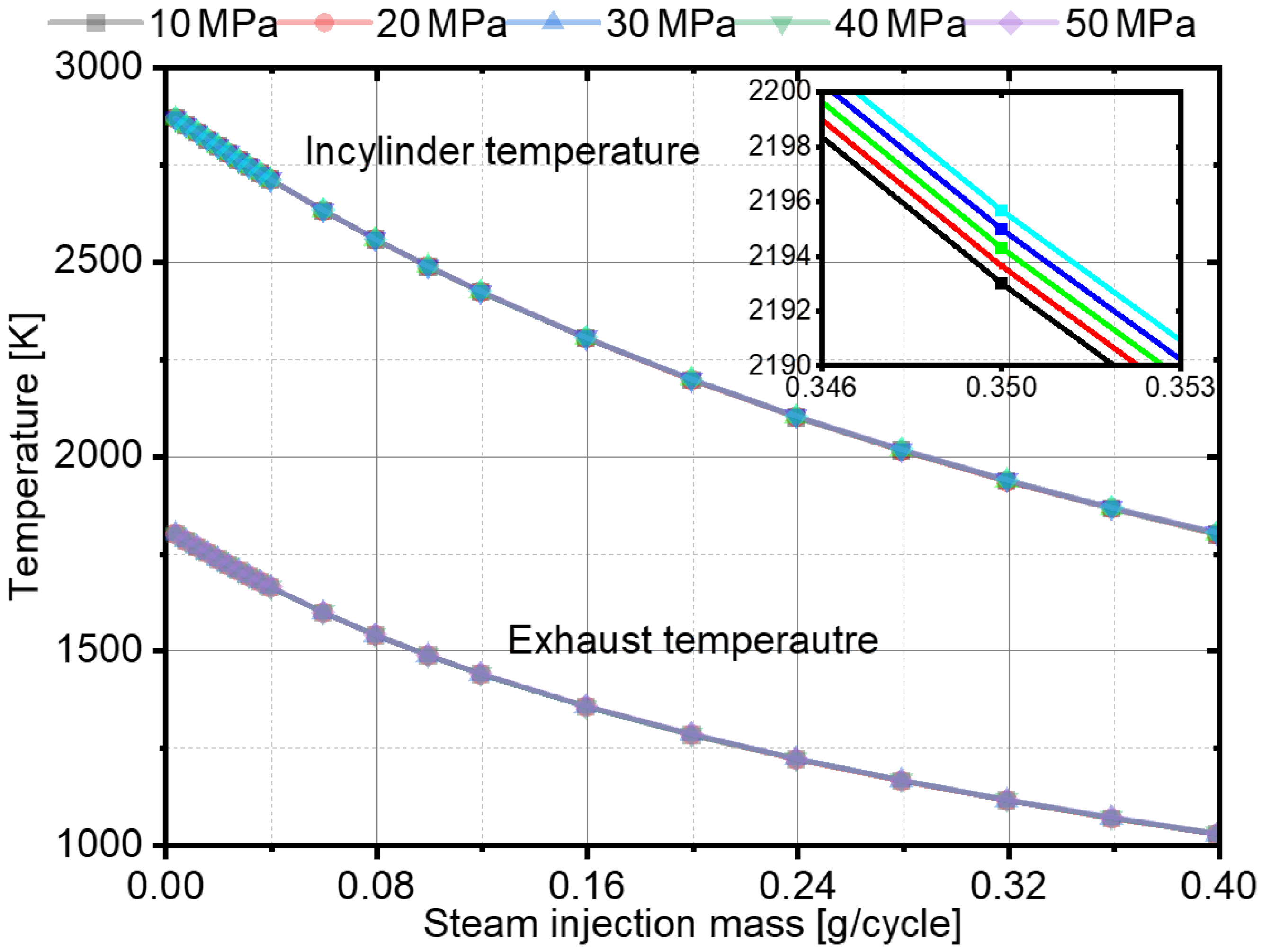
3.2. Effects of Injection Pressure on Cycle Performance

Injection pressure is a significant parameter qualifying the spray, which potentially affects the in-cylinder steam evaporation rate. Additionally, it also influences the temperature of saturated water in the thermodynamic calculation. In this section, the impacts of injection pressure on the proposed cycle are studied with the aim of taking full advantage of the latent heat of water-spray evaporation.
Figure 6 displays the relationships between in-cylinder/exhaust temperatures and steam injection mass at various injection pressures. The lower lines represent the exhaust temperature at the expansion end, while the upper lines are the in-cylinder temperatures at TDC. The injection pressure of the steam ranges from 10 to 50 MPa. As shown in Figure 6, the trends in in-cylinder and exhaust temperatures coincide with each other, and, in all cases, the gaps are too small to affect the thermodynamic characteristics. The results suggest that injection pressure has little influence on the thermodynamic state of steam. For instance, at a steam injection mass = 0.16 g/cycle, the in-cylinder temperature is 2097 K at 10 MPa injection pressure, which is 3 K less than the value for 50 MPa. The gap in temperature at the bottom dead centre between 10 MPa and 50 MPa is much smaller. The enthalpy of water steam at 20 MPa rises from 130.84 kJ/kg to 980.07 kJ/kg as injection temperature rises from 300 K to 500 K. Compared with the change caused by increasing the injection temperature, the change caused by increasing the injection pressure is negligible. Hence, increasing the steam injection pressure contributes little to thermal efficiency. The thermal efficiencies in the range of steam injection pressures considered are almost the same at different steam injection masses because this zero-dimensional model does not consider the spray process. With increases in injection pressure, the jet velocity rises significantly, and the Weber and Reynolds numbers increase. The atomization quality of the spray is enhanced with increasing injection pressure, which shortens its evaporation time and reduces negative effects on local combustion in the combustion chamber.

3.3. Effects of Intake Pressure on Cycle Performance

In the mixtures used in conventional SI engines, the pressure difference between each side of the throttle determines the intake mass, and the injected fuel mass is based on the AFR. The output power is applied to measure the engine load. Intake pressure and intake mass increase with increases in engine load, which enhances the indicated work carried out per unit volume of a cylinder, improves the indicated thermal efficiency and speeds up the evaporation in the combustion chamber. Therefore, the intake pressure and AFR usually indicate and control the engine load. In this study, the AFR of the proposed cycle is set to the stoichiometric ratio. The quantity of stoichiometric mixture in the combustion chamber is only decided by the intake pressure, which is the only parameter reflecting the engine load.
Figure 7a shows the relationship between in-cylinder/exhaust temperatures and steam injection mass at various intake pressures for a steam injection strategy of 450 K at 20 MPa. The range of intake pressures is 0.1–0.3 MPa, considering that naturally aspirated, turbocharged and supercharged engines will be investigated experimentally in the future. As shown in Figure 7a, the trends in the in-cylinder and exhaust temperatures of these three cases are similar. With increases in intake pressure, both temperatures rise slightly. For example, the in-cylinder temperature rises from 2193 K to 2238 K while the exhaust temperature rises from 1278 K to 1305 K at steam injection mass = 0.2 g/cycle as the intake pressure rises from 0.1 MPa to 0.3 MPa. This suggests that the intake pressure only has a slight influence on the in-cylinder temperature. It enhances the temperatures by increasing the density of the in-cylinder charge from 12.29 kg/m3 to 36.88 kg/m3 at TDC. Thus, as presented in Figure 7b, thermal efficiency increases linearly with steam injection mass because of the additional work generated by the high-temperature and -pressure water steam. The increase in intake pressure does not have much benefit for thermal efficiency. Thermal efficiency increases from 51.1% at 0.1 MPa intake pressure to 52.3% at 0.3 MPa intake pressure when steam injection mass = 0.2 g/cycle.

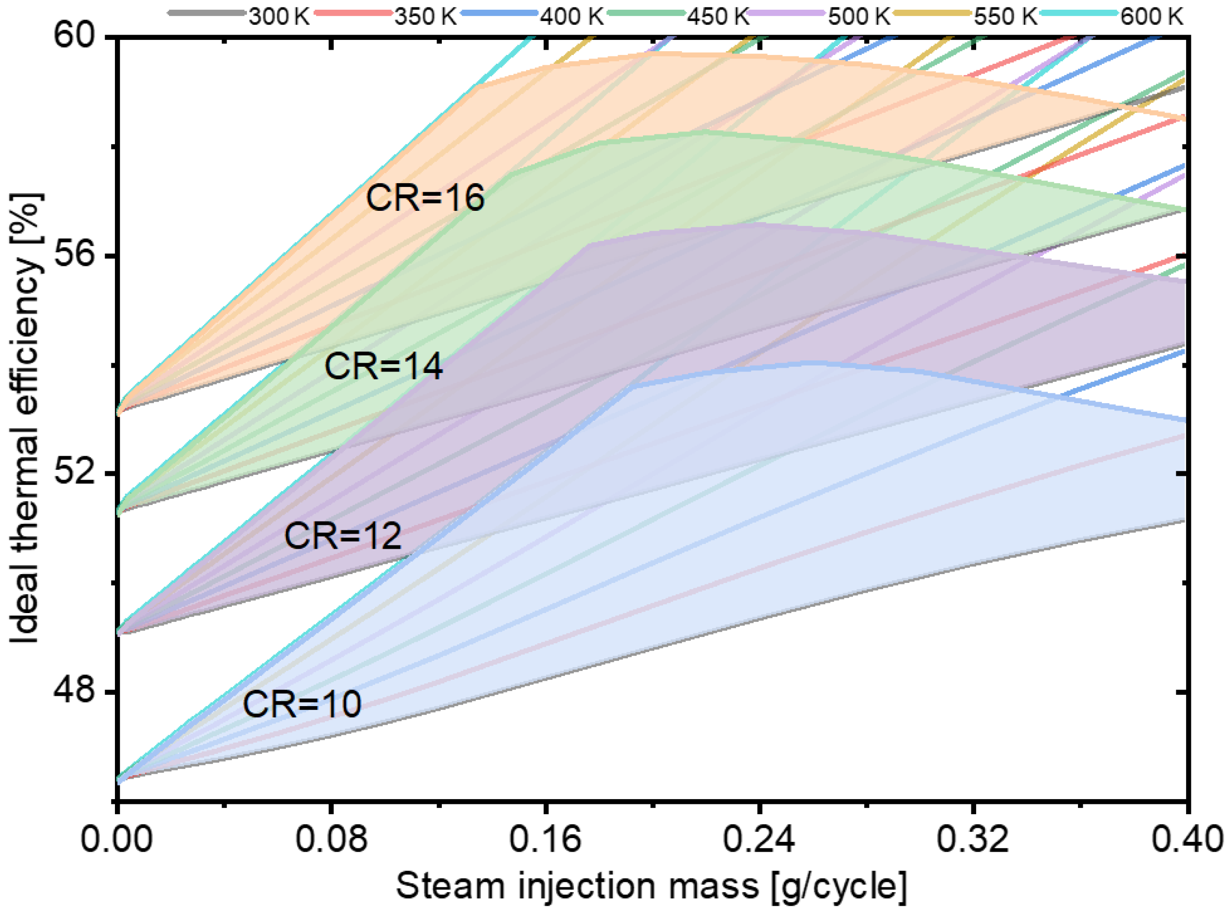
3.4. Analysis of Thermal Efficiency Boundary

It is an efficient method to enhance power output and thermal efficiency to increase the compression ratio. Due to limitations in the combustion chamber’s material strength and thermal load, increasing the compression ratio of engines is a great challenge. Steam injection technology is considered to be a technical solution to achieve controllable combustion at high compression ratios. Adding steam to a cylinder can decrease the temperature of the charge in a flexible manner, especially the temperature of the end gas in the cylinder, and increase knock suppression. Hence, a more extensive range of compression ratios is applicable. The thermal efficiency limit of the in-cylinder steam-assisted cycle is analyzed in this section.
Figure 8 shows plots of in-cylinder and exhaust temperatures at various compression ratios. The in-cylinder temperature increases slightly from 2323 K to 2385 K (steam injection mass = 0.2 g/cycle) as the compression ratio increases from 10 to 16, but the exhaust gas temperature decreases dramatically from 1368 K to 1250 K. This means that more energy is converted into work output, thereby improving the thermal efficiency. However, because of the increased compression ratio, the exhaust temperature decreases and the maximum steam injection temperature (as heated by the exchanger) is limited. This means that the gain in thermal efficiency brought by the in-cylinder steam-assisted cycle drops with decreases in steam injection temperature. Therefore, there is a trade-off between the compression ratio and the maximum temperature of injection steam heated by the exchanger. Hence, it is necessary to analyse the thermal boundary under different compression ratios.
Figure 9 presents the thermal efficiency and its boundary for an in-cylinder steam-assisted cycle under a compression ratio range of 10–16 at a 20 MPa injection pressure and 0.1 MPa intake pressure. To allow the designed heat exchanger to make the most of the exhaust energy, the temperatures of steam injected at different masses are validated using the method introduced in Section 2.3. As shown in Figure 9, Case 1, thermal efficiency greater than the boundary cannot be achieved. At a compression ratio of 10, the highest efficiency (about 54.0%) appears between steam injection temperatures of 500–550 K. For the in-cylinder steam-assisted cycle, the steam injection mass and temperature are the most critical parameters in cycle efficiency optimization. As analyzed above, the increase in steam injection mass increases thermal efficiency, but the exhaust gas temperature drops with increases in injected mass. If the steam injection mass is too high or the exhaust gas temperature is too low, the thermal efficiency cannot attain the best cycle performance. Therefore, there is a trade-off between the steam injection mass and specific enthalpy. For a given value of injected steam enthalpy, the capacity to enhance thermal efficiency varies.
As presented in Figure 9, higher thermal efficiency is achieved with the same steam injection mass at a higher compression ratio. Moreover, the thermal efficiency boundary rises from 54.0% at a compression ratio of 10 to 59.71% at CR = 16, and the maximum thermal efficiency reaches 59.71%. Overall, the increased compression ratio benefits the thermal efficiency of the in-cylinder steam-assisted cycle. A gain and loss analysis of thermal efficiency is presented in Figure 10. For each increment in compression ratio, the gains in WHR reduce by 0.25%, but the thermal efficiency gains because of the increased compression ratio increase by 1.1%, compensating for the efficiency loss in WHR. Consequently, the increase in compression ratio benefits the optimum thermal efficiency of the in-cylinder steam-assisted cycle, and the gains compensate for the loss in WHR.
According to the analysis above, there is an efficiency boundary for the in-cylinder steam-assisted cycle under different compression ratios. For a constant-volume heating cycle, the ideal efficiency can be calculated as follows:
η i = 1 ε   1 k
where k is the specific heat ratio or adiabatic exponent and ε is the compression ratio. In Figure 11, the black line indicates the ideal thermal efficiency, and the adiabatic exponent is 1.4. Similarly, the blue line shows the counterpart of the Otto cycle and the adiabatic exponent is calculated as 1.27. The proposed cycle is also a constant-volume heating cycle so that the thermal efficiency can be summarized according to Equation (22), and is represented by the red line. Obviously, compared with the Otto cycle, the thermal efficiency boundary rises dramatically, and the adiabatic exponent of the combined cycle increases from 1.27 to 1.333. An in-cylinder steam-assisted cycle based on the Otto cycle combines the advantages of a reheated Rankine cycle and steam injection technology. First, exhaust energy is recovered through a heat exchanger. Higher steam temperatures mean higher specific enthalpy and heat energy recovery from exhaust gases, thereby making the most of the engine’s waste heat and enhancing its thermal efficiency. Second, in addition to the effective utilisation of waste heat, the overheated steam injection has many advantages, such as controlling abnormal combustion precisely and quickly, increasing the specific heat ratio and heat absorption capacity, and increasing the working medium in the expansion stroke. Hence, in-cylinder steam-assisted cycles have broad application prospects.

4. Conclusions

In this study, the thermodynamic feasibility of an in-cylinder steam-assisted cycle is verified in a spark ignition engine. Some critical parameters, such as injection temperature, steam injection pressure, and intake pressure, are discussed for various steam injection masses. The thermal efficiency boundaries of this technology are also analysed at different compression ratios to investigate its maximum potential thermal efficiency, which provides considerable guidance for the future experimental and numerical studies of in-cylinder steam assist technology into modern engines. The following conclusions can be drawn from this study.
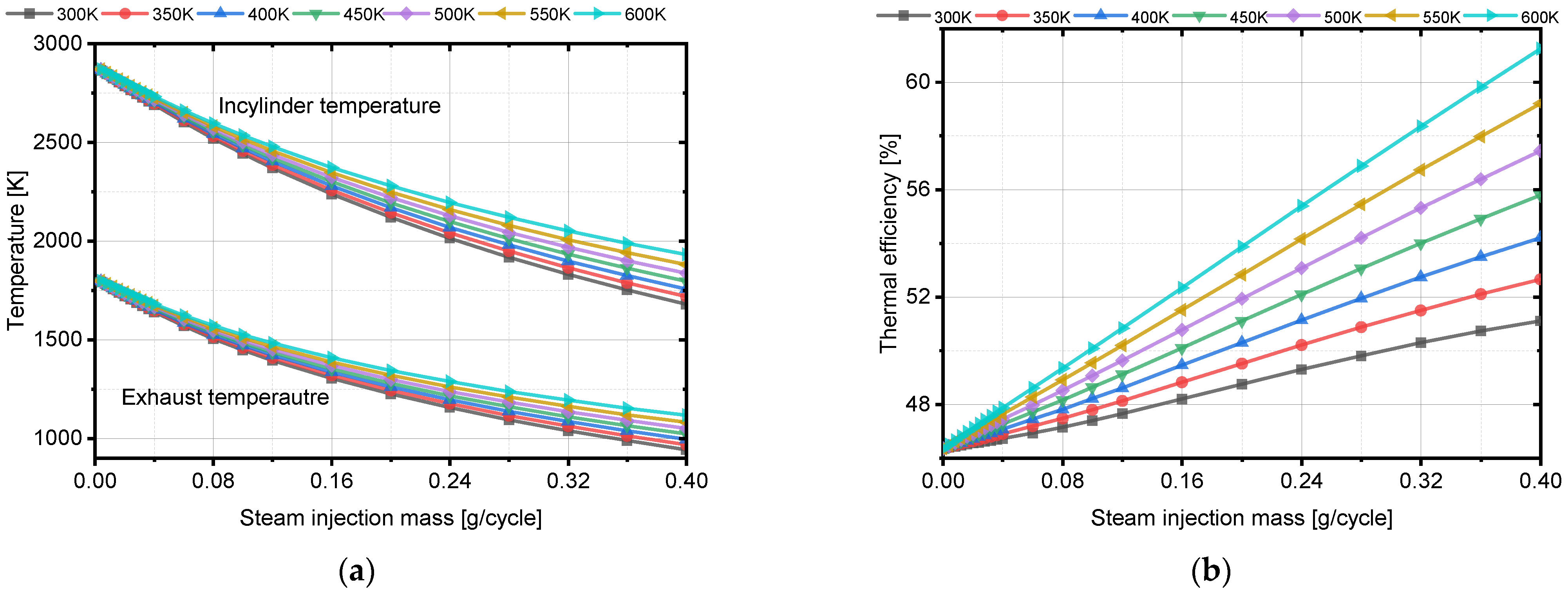
  • Theoretical calculations based on the developed thermodynamic model show that both steam injection temperature and injection mass improve thermal efficiency. Without steam injection, the base thermal efficiency of the prototype is 46.34%. This gradually increases to 51.11% with increases in steam injection mass and to 61.25% at a steam injection temperature of 600 K. Increases in steam injection pressure contribute little to thermal efficiency.
  • The thermal efficiency of the developed cycle increases with the injected steam enthalpy, which is determined by the exhaust gas energy. However, excessive steam decreases the exhaust temperature, so there is a trade-off between them. According to the assumption of instant in-cylinder steam evaporation, the optimum thermal efficiency of the in-cylinder steam-assisted cycle is 59.71% at an injection temperature of 500 K and a steam injection mass of 0.2 g/cycle.
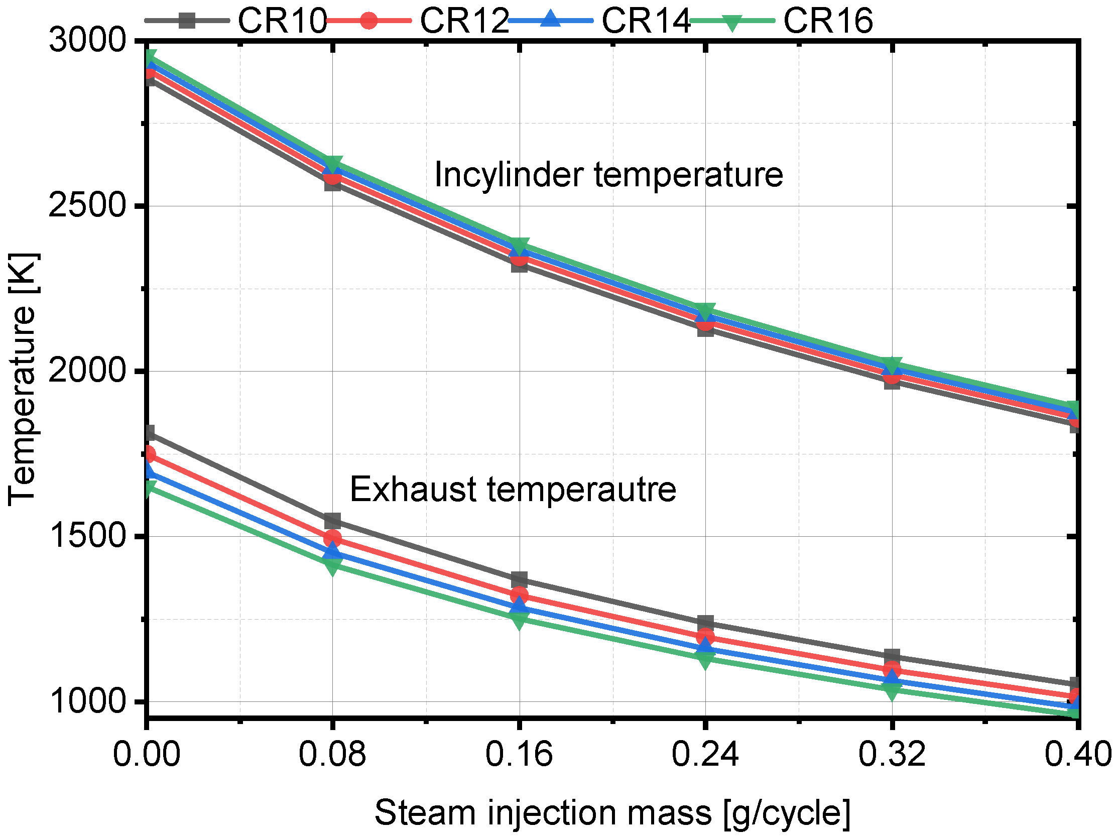
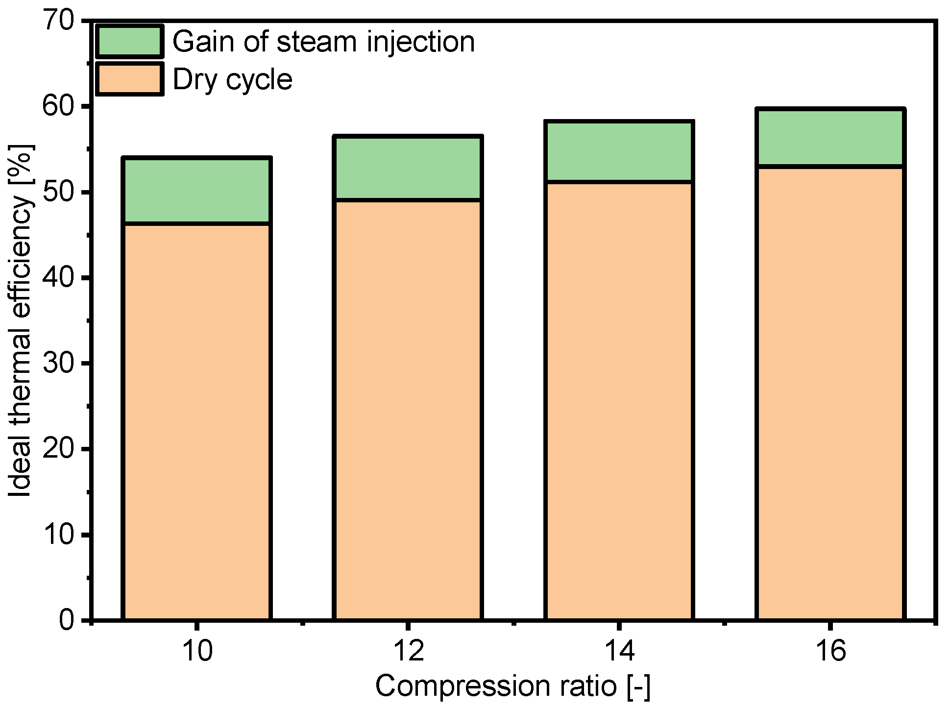
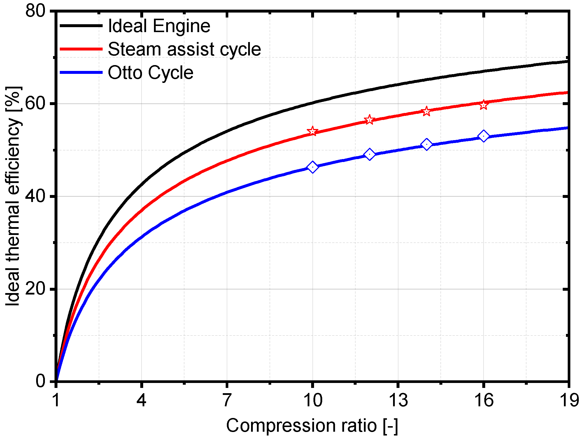
  • The maximum gain in thermal efficiency achieved with the cycle is 14.5% at a compression ratio of 10. From a thermodynamic perspective, the reason is that the specific heat ratio rises from 1.27 to 1.333, which improves the thermal-heat conversion efficiency. Similarly, increases in compression ratio also benefit the optimum thermal efficiency of the in-cylinder steam-assisted cycle. The optimum thermal efficiency can be increased from 54.0% to 59.71% by increasing the compression ratio from 10 to 16.
  • As this work conducts theoretical investigation regarding in-cylinder steam assist, the real in-cylinder combustion process, intake and exhaust gas exchange process, non-ideal gas effect and other realistic process are simplified, the results of this work only provide theoretical results and guidance for future in-cylinder steam assist application within modern internal combustion engine. Future work will be focused on enhancing the precision of the theoretical model by establishing 1-D or 3-D models.

Author Contributions

Conceptualization, J.W. and Z.K.; Formal analysis, Z.K.; Funding acquisition, Z.K. and Z.W.; Investigation, J.W.; Methodology, J.W. and Z.K.; Project administration, Z.K. and Z.W.; Resources, Z.K. and Z.W.; Software, J.W.; Supervision, Z.W.; Validation, J.W.; Writing—original draft, J.W.; Writing—review & editing, Z.K. All authors have read and agreed to the published version of the manuscript.

Funding

This research was funded by the National Natural Science Foundation of China (NSFC) (Grant Nos. 52002043 and U1832179), China Postdoctoral Science Foundation (Grant No.2021M700581), Chongqing Technology Innovation and Application Development Project (Grant No. cstc2020jscx-msxmX0170) and the Fundamental Research Funds for the Central Universities (Grant No. 2022CDJXY-006).

Institutional Review Board Statement

Not applicable.

Informed Consent Statement

Not applicable.

Conflicts of Interest

The authors declare no conflict of interest.

Nomenclature

Abbreviations
AFRAir/fuel ratio
AKIAnti-knock index
ATDCAfter top dead centre
BEVBattery electric vehicle
BSFCBrake specific fuel consumption
CACrank angle
COCarbonic oxide
FCVFuel cell vehicle
GHGGreenhouse gas
HEVHybrid electric vehicle
ICEInternal combustion engine
ICEVInternal combustion engine vehicle
ICRCInternal combustion Rankine cycle
LMTDLogarithmic mean temperature difference
NTUNumber of transfer units
TDCTop dead centre
WHRWaste heat recovery
Symbols
HIndicated thermal efficiency
μ Dynamic viscosity
λ Carbon steel thermal conductivity
Φ Heat flux
AHeat transfer area
c p Specific heat at constant pressure
c v Specific heat at constant volume
DShell diameter
DTube diameter
HSpecific enthalpy
KHeat transfer coefficient
KFluid thermal conductivity
LTube length
m Intake charge mass
m ˙ Mass flow rate
NNumber of tubes
N u Nusselt number
P r Prandtl number
P t Tube centre distance
Q Thermal energy
R e Reynolds number
T Temperature
U Internal energy
W Work
Subscripts
AirAir parameters
GExhaust gases parameters
IInner parameters of tubes
InInlet of heat exchanger
IndicatedIndicated parameters
MaxMaximum value
MinMinimum value
OOuter parameters of tubes
OutOutlet of heat exchanger
PumpPump parameters
WWater steam parameters
WallTube wall

References

  1. Alagumalai, A. Internal combustion engines: Progress and prospects. Renew. Sustain. Energy Rev. 2014, 38, 561–571. [Google Scholar] [CrossRef]
  2. Hannah, R.; Max, R. CO2 and Greenhouse Gas Emissions. Our World Data. 2020. Available online: https://ourworldindata.org/co2-and-other-greenhouse-gas-emissions (accessed on 1 August 2020).
  3. GB 27999-2019; Fuel Consumption Evaluation Methods and Targets for Passenger Cars. SAC: Beijing, China, 2019.
  4. Zardini, A.; Bonnel, P. Real Driving Emissions Regulation. European Methodology to Fine Tune the EU Real Driving Emissions Data Evaluation Method; Publications Office of the European Union: Luxembourg, 2020. [Google Scholar]
  5. Reitz, R.D.; Ogawa, H.; Payri, R.; Fansler, T.; Kokjohn, S.; Moriyoshi, Y.; Agarwal, A.; Arcoumanis, D.; Assanis, D.; Bae, C.; et al. IJER editorial: The future of the internal combustion engine. Int. J. Engine Res. 2020, 21, 3–10. [Google Scholar] [CrossRef] [Green Version]
  6. Heywood, J.; MacKenzie, D.; Akerlind, I.; Bastani, P.; Berry, I.; Bhatt, K.; Chao, A.; Chow, E.; Karplus, V.; Keith, D. On the Road toward 2050: Potential for Substantial Reductions in Light-Duty Vehicle Energy Use and Greenhouse Gas Emissions; Massachusetts Institute of Technology: Cambridge, MA, USA, 2015. [Google Scholar]
  7. Nakata, K.; Nogawa, S.; Takahashi, D.; Yoshihara, Y.; Kumagai, A.; Suzuki, T. Engine technologies for achieving 45% thermal efficiency of S.I. engine. SAE Int. J. Engines 2015, 9, 179–192. [Google Scholar] [CrossRef]
  8. Sok, R.; Yamaguchi, K.; Kusaka, J. Prediction of ultra-lean spark ignition engine performances by quasi-dimensional combustion model with a refined laminar flame speed correlation. J. Energy Resour. Technol. 2020, 143, 032306. [Google Scholar] [CrossRef]
  9. Ratnak, S.; Kusaka, J.; Daisho, Y.; Yoshimura, K.; Nakama, K. Experiments and simulations of a lean-boost spark ignition engine for thermal efficiency improvement. SAE Int. J. Engines 2015, 9, 379–396. [Google Scholar]
  10. Zhao, J. Research and application of over-expansion cycle (Atkinson and Miller) engines—A review. Appl. Energy 2017, 185, 300–319. [Google Scholar] [CrossRef]
  11. Kaminaga, T.; Yamaguchi, K.; Ratnak, S.; Jin, K.; Yamakawa, M. A Study on Combustion Characteristics of a High Compression Ratio SI Engine with High Pressure Gasoline Injection. In Proceedings of the 14th International Conference on Engines & Vehicles, Napoli, Italy, 12–16 September 2019. [Google Scholar]
  12. Fraidl, G.; Kapus, P.; Mitterecker, H.; WeißbÄck, M. Internal combustion Engine 4.0. TZ Worldw. 2018, 79, 26–33. [Google Scholar] [CrossRef]
  13. Wu, Z.; Wu, J.; Kang, Z.; Deng, J.; Hu, Z.; Li, L. A review of water-steam-assist technology in modern internal combustion engines. Energy Rep. 2021, 7, 5100–5118. [Google Scholar] [CrossRef]
  14. Zhu, S.; Hu, B.; Akehurst, S.; Copeland, C.; Lewis, A.; Yuan, H.; Kennedy, I.; Bernards, J.; Branney, C. A review of water injection applied on the internal combustion engine. Energy Convers. Manag. 2019, 184, 139–158. [Google Scholar] [CrossRef]
  15. Gonca, G.; Sahin, B. Effect of turbo charging and steam injection methods on the performance of a Miller cycle diesel engine (MCDE). Appl. Therm. Eng. 2017, 118, 138–146. [Google Scholar] [CrossRef]
  16. Gonca, G.; Sahin, B. The influences of the engine design and operating parameters on the performance of a turbocharged and steam injected diesel engine running with the Miller cycle. Appl. Math. Model. 2016, 40, 3764–3782. [Google Scholar] [CrossRef]
  17. Gonca, G. Effects of engine design and operating parameters on the performance of a spark ignition (SI) engine with steam injection method (SIM). Appl. Math. Model. 2017, 44, 655–675. [Google Scholar] [CrossRef]
  18. Parlak, A. A study on performance and exhaust emissions of the steam injected DI diesel engine running with different diesel-conola oil methyl ester blends. J. Energy Inst. 2019, 92, 717–729. [Google Scholar] [CrossRef]
  19. Cesur, I.; Parlak, A.; Ayhan, V.; Boru, B.; Gonca, G. The effects of electronic controlled steam injection on spark ignition engine. Appl. Therm. Eng. 2013, 55, 61–68. [Google Scholar] [CrossRef]
  20. Zhang, Z.; Li, L. Investigation of in-cylinder steam injection in a turbocharged diesel engine for waste heat recovery and NOx emission control. Energies 2018, 11, 936. [Google Scholar] [CrossRef] [Green Version]
  21. Kang, Z.; Wu, Z.J.; Zhang, Z.H.; Deng, J.; Hu, Z.J.; Li, L.G. Study of the combustion characteristics of a HCCI engine coupled with oxy-fuel combustion mode. SAE Int. J. Engines 2017, 10, 908–916. [Google Scholar] [CrossRef]
  22. Kang, Z.; Wu, Z.; Fu, L.; Deng, J.; Hu, Z.; Li, L. Experimental study of ion current signals and characteristics in an internal combustion rankine cycle engine based on water injection. J. Eng. Gas Turbines Power 2018, 140, 111506. [Google Scholar] [CrossRef]
  23. Kang, Z.; Zhang, Z.; Deng, J.; Li, L.; Wu, Z. Experimental research of high-temperature and high-pressure water jet characteristics in ICRC engine relevant conditions. Energies 2019, 12, 1763. [Google Scholar] [CrossRef] [Green Version]
  24. Kang, Z.; Wu, Z.; Deng, J.; Hu, Z.; Li, L. Experimental research of diffusion combustion and emissions characteristics under oxy-fuel combustion mode. J. Eng. Gas Turbines Power 2020, 142, 061002. [Google Scholar] [CrossRef]
  25. Wu, Z.-J.; Yu, X.; Fu, L.-Z.; Deng, J.; Li, L.-G. Experimental study of the effect of water injection on the cycle performance of an internal-combustion Rankine cycle engine. Proc. Inst. Mech. Eng. Part D J. Automob. Eng. 2014, 228, 580–588. [Google Scholar] [CrossRef]
  26. Wu, Z.J.; Yu, X.; Fu, L.Z.; Deng, J.; Hu, Z.J.; Li, L.G. A high efficiency oxyfuel internal combustion engine cycle with water direct injection for waste heat recovery. Energy 2014, 70, 110–120. [Google Scholar] [CrossRef]
  27. Wu, Z.J.; Kang, Z.; Deng, J.; Hu, Z.J.; Li, L.G. Effect of oxygen content on n-heptane auto-ignition characteristics in a HCCI engine. Appl. Energy 2016, 184, 594–604. [Google Scholar] [CrossRef]
  28. Wu, Z.J.; Fu, L.Z.; Gao, Y.; Yu, X.; Deng, J.; Li, L.G. Thermal efficiency boundary analysis of an internal combustion Rankine cycle engine. Energy 2016, 94, 38–49. [Google Scholar] [CrossRef]
  29. Wu, Z.; Zhang, Z.; Li, W.; Chen, H.; Li, Z.; Deng, J. Morphology analysis on the effect of injection pressure on jet trajectory deviation of multi-jet sprays. Fuel 2019, 243, 362–370. [Google Scholar] [CrossRef]
  30. Li, L.; Zhang, Z. Investigation on steam direct injection in a natural gas engine for fuel savings. Energy 2019, 183, 958–970. [Google Scholar] [CrossRef]
  31. Conklin, J.C.; Szybist, J.P. A highly efficient six-stroke internal combustion engine cycle with water injection for in-cylinder exhaust heat recovery. Energy 2010, 35, 1658–1664. [Google Scholar] [CrossRef]
  32. Arabaci, E.; İçingür, Y.; Solmaz, H.; Uyumaz, A.; Yilmaz, E. Experimental investigation of the effects of direct water injection parameters on engine performance in a six-stroke engine. Energy Convers. Manag. 2015, 98, 89–97. [Google Scholar] [CrossRef]
  33. Fu, J.; Liu, J.; Ren, C.; Wang, L.; Deng, B.; Xu, Z. An open steam power cycle used for IC engine exhaust gas energy recovery. Energy 2012, 44, 544–554. [Google Scholar] [CrossRef]
  34. Zhao, R.; Li, W.; Zhuge, W.; Zhang, Y.; Yin, Y. Numerical study on steam injection in a turbocompound diesel engine for waste heat recovery. Appl. Energy 2017, 185, 506–518. [Google Scholar] [CrossRef]
  35. Zhao, R.; Zhang, Z.; Zhuge, W.; Zhang, Y.; Yin, Y. Comparative study on different water/steam injection layouts for fuel reduction in a turbocompound diesel engine. Energy Convers. Manag. 2018, 171, 1487–1501. [Google Scholar] [CrossRef]
  36. Zhu, S.; Deng, K.; Qu, S. Thermodynamic analysis of an in-cylinder waste heat recovery system for internal combustion engines. Energy 2014, 67, 548–556. [Google Scholar] [CrossRef]
  37. Zhu, S.; Liu, S.; Qu, S.; Deng, K. Thermodynamic and experimental researches on matching strategies of the pre-turbine steam injection and the Miller cycle applied on a turbocharged diesel engine. Energy 2017, 140, 488–505. [Google Scholar] [CrossRef]
Figure 1. Schematic and P-V curve of the in-cylinder steam-assisted cycle.
Applsci 12 06818 g001
Figure 2. Thermodynamic model validation with experiment (Tsteam = 473 K; Msteam = 0.03 g/cycle; Psteam = 15 MPa; Pinkate = 0.1 MPa; CR = 10).
Applsci 12 06818 g002
Figure 3. Flowchart of boundary verification.
Applsci 12 06818 g003
Figure 4. Relationship between cycle performance and steam injection mass at various injection temperatures (Psteam = 20 MPa; Pinkate = 0.1 MPa; CR = 10). (a) In-cylinder/exhaust temperatures; (b) Thermal efficiency.
Applsci 12 06818 g004
Figure 5. Work output according to steam injection mass (Psteam = 20 MPa; Tsteam = 450 K; Pintake = 0.1 MPa; CR = 10).
Applsci 12 06818 g005
Figure 6. Relationships between in-cylinder/exhaust temperatures and steam injection mass at various injection pressures (Tsteam = 450 K; Pinkate = 0.1 MPa; CR = 10).
Applsci 12 06818 g006
Figure 7. Relationship between cycle performance and steam injection mass at various intake pressures (Tsteam = 450 K; Psteam = 20 MPa; CR = 10). (a) In-cylinder/exhaust temperatures; (b) Thermal efficiency.
Applsci 12 06818 g007
Figure 8. Relationships between in-cylinder/exhaust temperatures and steam injection mass at different compression ratios (Tsteam = 450 K; Psteam = 20 MPa; Pintake = 0.1 MPa).
Applsci 12 06818 g008
Figure 9. Thermal efficiency and its boundary at different compression ratios (Psteam = 20 MPa; Pintake = 0.1 MPa).
Applsci 12 06818 g009
Figure 10. Comparison of thermal efficiencies at different compression ratios.
Applsci 12 06818 g010
Figure 11. Thermal efficiency boundaries at different compression ratios.
Applsci 12 06818 g011
Table 1. Initial conditions, assumptions, and boundaries.
ItemValue
Initial conditions
FuelIso-octane
Ignition modeSpark ignition
Low Heat value (kJ/kg)47.67
Air-fuel ratio (-)14.7
Initial temperature (K)298
Assumptions
Heat transferAdiabatic
Steam injection timingInstantaneous at TDC
Steam and air mixingInstantaneous at TDC
Boundaries
Intake pressure (MPa)0.1~0.3
Compression ratio (-)10~16
Steam injection temperature (K)300~600
Steam injection pressure (MPa)20~50
Steam injection mass (g/cycle)0~0.4
Table 2. Engine type and geometry.
ItemValue
Engine type SI engine
Bore (mm)74
Stroke (mm)86.6
Connecting rod length (mm)127.9
Compression ratio (-)10
Table 3. Input parameters of the heat exchanger design.
ItemValue
Engine speed5000 r/min
Steam mass0.2
Steam inlet temperature298 K
Steam outlet temperature (target)463 K
Table 4. Designed parameters of a heat exchanger.
ItemValue
Outer diameter of tubes (do)12 mm
Inner diameter of tubes (di)10 mm
Centre distance (Pt)17 mm
Number of tubes (N)43
Length of tubes (L)450 mm
Baffle space (Lb)50 mm
Shell diameter (Di)140 mm
Heat exchanger area (A)0.73 m2
Publisher’s Note: MDPI stays neutral with regard to jurisdictional claims in published maps and institutional affiliations.

