Featured Application
3-phase industrial PFC converter.
Abstract
In this paper, the main aim of the study was the investigation of the possibilities of power inductor design, reflecting the performance of the component itself, as well as the operational efficiency of the power factor correction (PFC) converter. PFC inductors represent a key component of the converter, while within the design of any magnetic component, several design rules must be considered to provide proper operational performance. Here we discuss skin-effect, while the proximity effect and formation of fringing flux pose a more serious problem in terms of mitigating their negative impact. Therefore, in this study, the space is devoted exclusively to the analysis of the impact of the fringing flux of the PFC inductor and subsequently to the possibilities of its suppression. The resulting optimizations are reflected in the investigation of the operational efficiency of the PFC converter.
1. Introduction
In many cases, introducing an air gap can be of great use. Often, engineers may think that introducing an air gap increases the maximum flux density a core can handle. This is not true. Instead, and more correctly, the air gap introduces a large amount of reluctance within the core. It is within the gap that much of the energy is stored. A large reluctance requires a greater magnetomotive force to push the same flux within the core than without the gap. This is much like a large resistance within an electrical circuit that requires a greater voltage to push the same current than a lower resistance would require [1,2,3,4].
The efficiency of energy conversion and power density are the key criteria in the design of power converters. Packaging constraints, the demand for reduced size, and the best performance frequently force power supply engineers to re-evaluate their approach to building magnetic components. Gapped ferrite toroids can find application in compact/low profile designs and potentially be a convenient solution compared with ferrite E-cores or toroidal powder cores.
Large gaps, however, produce magnetic ‘fringing’ causing eddy current losses in adjacent conductors, significantly impacting converter efficiency. This extra power loss can be observed in the form of ‘hot spots’ [5,6,7,8].
Designing inductive components is a complex problem, where electrical and magnetic issues must be considered. From an electrical point of view, such aspects must be regarded as the skin and the proximity effects, current densities, and power losses of windings, insulation between turns and layers, voltages, currents, frequency, and temperature of operation. From a magnetic point of view, the important aspects are inductance parameters, saturation flux density level, saturation current in windings, the magnetic permeability of core material, fringing flux effects, cross-sections, and dimensions of the window area of a magnetic core [9,10,11,12,13].
Inductors, used in power electronic applications, are very often designed with an air-gapped magnetic core. Implementation of an air gap influences the shape of the B-H curve of the magnetic circuit, decreasing the effective inductance and increasing the saturation current of an inductor. Designing an inductor with an air gap is very complicated because magnetic material is described by nonlinear characteristics of the B-H curve, saturation, and power losses. Moreover, the high sensitivity of magnetic material in the manufacturing process must be taken into account. Additionally, the implementation of an air gap increases the fringing flux phenomenon which must be taken into account because of electromagnetic interferences (EMI) aspects, since fringing flux causes higher propagation of electromagnetic disturbances [14].
For power inductors, which are mainly storage chokes working at nominal currents in a range of 50–200 A and a frequency between 3 and 100 kHz, often, gapped amorphous or nanocrystalline cores are used. They offer a much higher possible saturation flux density Bsat compared to ferrites (1.2–1.5 T instead of 0.3–0.4 T for ferrites), which makes them the preferred choice to build smaller inductors. To store a high amount of energy, power inductors built from amorphous or nanocrystalline materials require a relatively large air gap, in the range of 2–10 mm. Fringing flux, entering the space around a big air gap, is problematic, due to forced eddy current losses. Ways to overcome this problem are the usage of multiple small air gaps, which causes a larger manufacturing effort, or the usage of lower permeability powder materials with a permeability μr of 10 to 26, inserted instead of an air gap. While combining two materials to form a core without an air gap, both should have a usable flux density Buse in the same range. KoolMμ (Sendust) material has a soft saturation curve with a Bsat in the range of around 1 T. The preferred range of magnetic induction in amorphous and nanocrystalline cores is also, due to core loss effects, in the range up to 1 T [4,7,15,16,17,18].
When approaching the air gap, the magnetic field lines, which until that point are entirely enclosed by the core, tend to fringe out beyond the cross-sectional area of the core and enter the surrounding medium, usually copper winding [19].
In this paper, the research task is devoted to the practical verification of the above statements from the mentioned studies. One of the main aims is also to examine other phenomena related to fringing flux, which have not yet been considered in terms of the construction or operational performance of the power converter. Many studies have addressed the impact of fringing flux on the properties of a magnetic component. However, the examination of the secondary impact, i.e., to the system operation of the power converter as a whole, was no longer sufficiently investigated. The article gradually presents the influence of fringing flux from the thermal performance point of view of the magnetic component, while a comparison between a component with one air gap and with several smaller distributed gaps is also presented. Subsequently, the space is devoted to the analysis of the influence of fringing flux in terms of the design of the magnetic component, while the main indicator is the stability of the inductance value of the PFC converter coil. The final consequence of the analysis is the influence of various coil designs forcing the reduction of fringing flux, and consequent evaluation of the impact on the efficiency parameter of the PFC converter.
2. Effect of the Air Gap in Inductor Magnetic Core—Air Gap of Inductor Reflected in the Generation of Fringing Flux
Generally, the main function of the coil’s air gap is to store the energy of the inductor. This effect can be described by Equation (1); the left part represents the operational variables of the coil and the right part reflects inductor core dimensions for given permeability μr and maximum saturation Bm.
where L—inductance of the coil, Im—maximum current of the inductor, Bm—saturation induction, SFe—core cross-section area, lFe—mean length path, lv—length of the air gap, μr—relative permeability, and μ0—permeability of vacuum.
Considering the geometry and design of the inductor core, if the situation when lv = 0, i.e., the core is without air gap, the product of values LIm2 requires the high product of the second part SFe and lFe. It will then reflect into the bulky and heavy magnetic core. On the other hand, the higher the relative permeability of the magnetic material μr, the higher the product of SFe and lFe required. Moreover, the magnetic conductivity of the core is defined by the conductivity of the ferromagnetic material. Because of the dependency μr = f(B), the magnetic conduction is also dependent on the induction, thus on the value of the coil´s current. Based on this fact, the value of inductance is dependent on the value of current. As a result, a core without an air gap can be saturated relatively quickly. In the case when lv >> lfe/μr, the product of SFe and lFe shall be lowered targeting the required product of LIm2, resulting in smaller dimensions of the magnetic core. Simultaneously, if magnetic resistance Rv is much higher than RFe, then the magnetic resistance of ferromagnetic material has limited influence on magnetic conduction. The value of the inductance will then be practically independent of the properties of ferromagnetic material, thus the inductance will be independent of the value of the inductor current.
An air gap enables optimization of the dimensions of the core and also meets the stabilization function of the component. Care must be taken not to exceed the value of Bm due to the consequent drop of the relative permeability and value of inductance.
Although induction B is the same in the air gap as in the ferromagnetic part, it has a large magnetic resistance due to the low permeability of the air gap. As a result, most of the intensity of the magnetic field is concentrated in the air gap. The product of B and H is related to energy density, and it follows that most of the energy is stored in the air gap. It further follows that the resulting magnetic core may be smaller. The ferromagnetic part of the magnetic circuit then acts as a pole piece, which allows realizing an air gap of defined, relatively small length, and dimensions reflecting the arrangement of the winding. In summary, it is valid that achieving the required value of inductance a coil without an air gap would have significantly larger dimensions than a coil of ferromagnetic material with an air gap.
The length of the air gap must be selected correctly because of the side effect of the fringing flux (Figure 1), which is responsible for the increase in component losses. If the air gap is too long, the magnetic flux of the core would interfere with the winding. In contrast, a small air gap requires a larger core and thus the volume of the resulting converter would be increased.
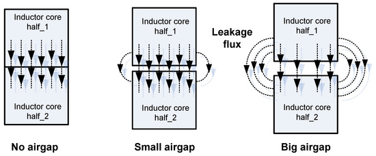
Figure 1.
Representation of the magnetic core without air gap (left), with small air gap (middle), and with large air gap (right).
2.1. Analysis of the Fringing Flux Influence on PQ-Type Ferrite Core
The effect of the fringing flux occurs around each air gap and its magnitude depends on the size of the air gap. The displacement of the magnetic flux around the gap outside the ferromagnetic material is due to the significantly higher magnetic resistance of the air gap compared to the magnetic resistance of the ferromagnetic material. In some cases, this effect interferes with the winding of the coil, which reflects in the generation of eddy currents in the winding. Eddy currents are responsible for losses and heating of the winding. Generally, there are two ways to prevent this side effect of the fringing flux:
- ▪
- Delimitation of the space around the air gap (Figure 2) by nonconducting, nonmagnetic material, ensures that the coil winding is sufficiently distant from the magnetic flux originating from the magnetic core to the air.
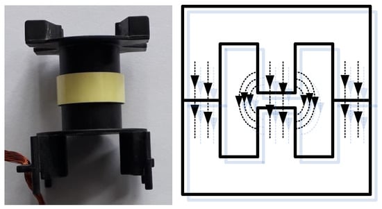 Figure 2. Example of space exclusion on the magnetic core bobbin (left) within the space of the core air gap (right).
 - ▪
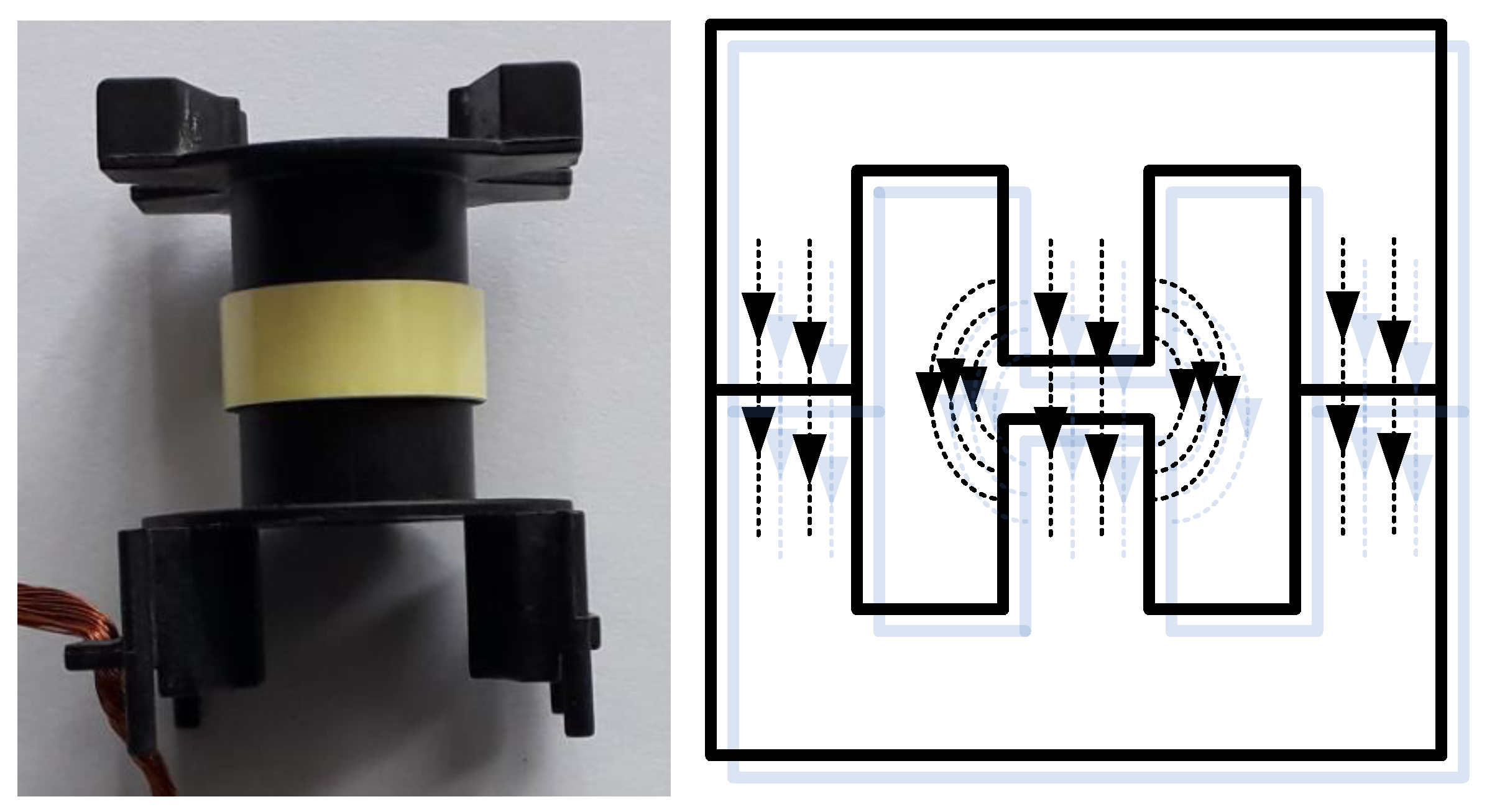
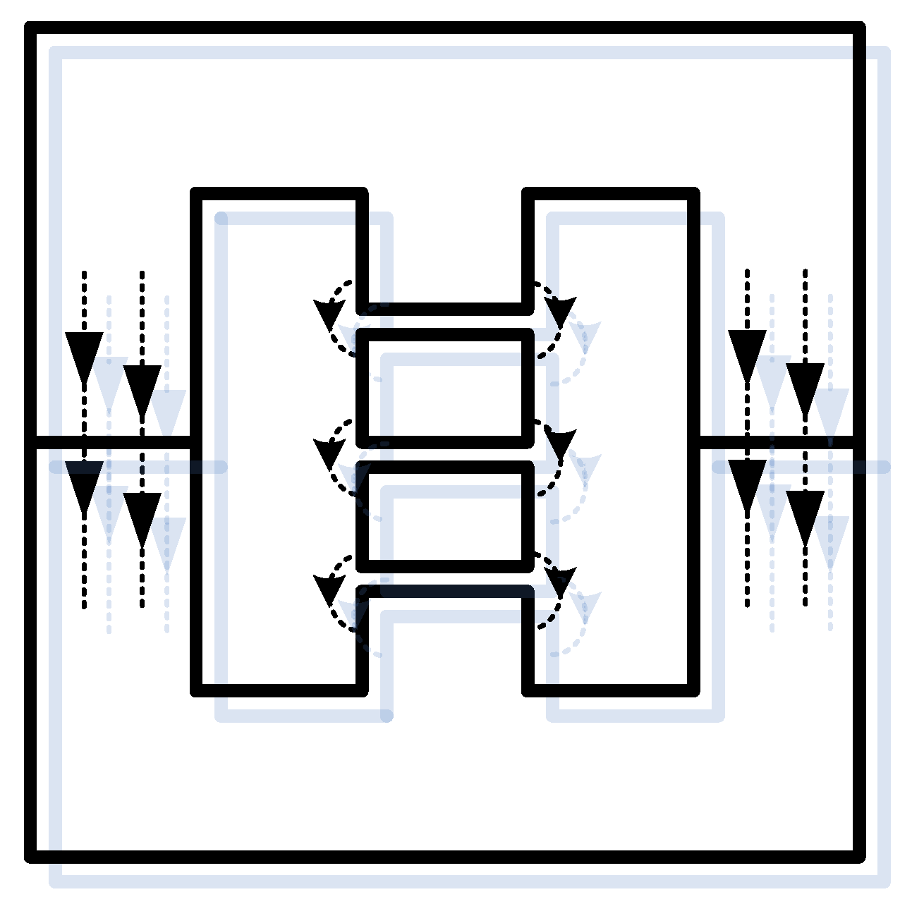
- Create a distributed air gap (Figure 3) in the core by replacing the large air gap with several shorter air gaps, thus minimizing the amount of the fringing flux.
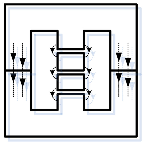 Figure 3. Example of the distributed air gap implementation within the E-shape core.
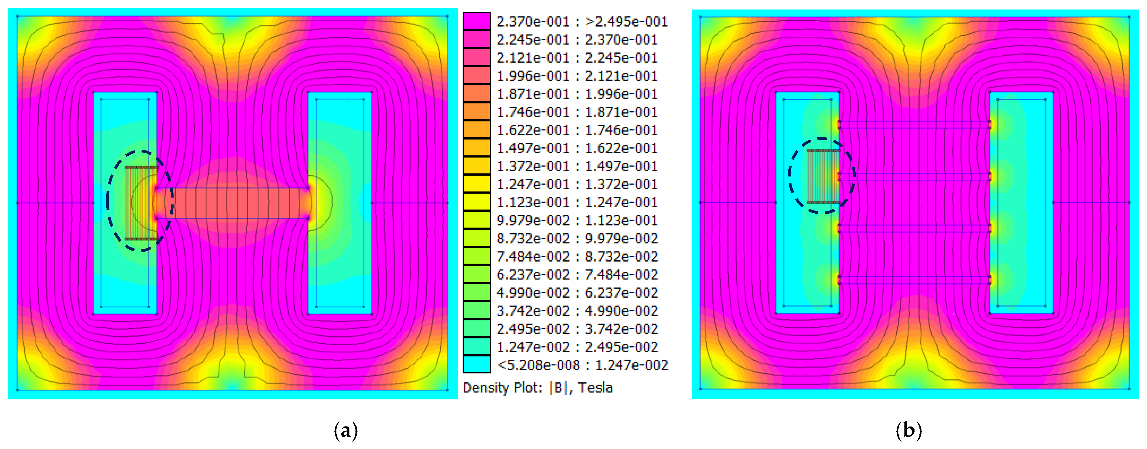
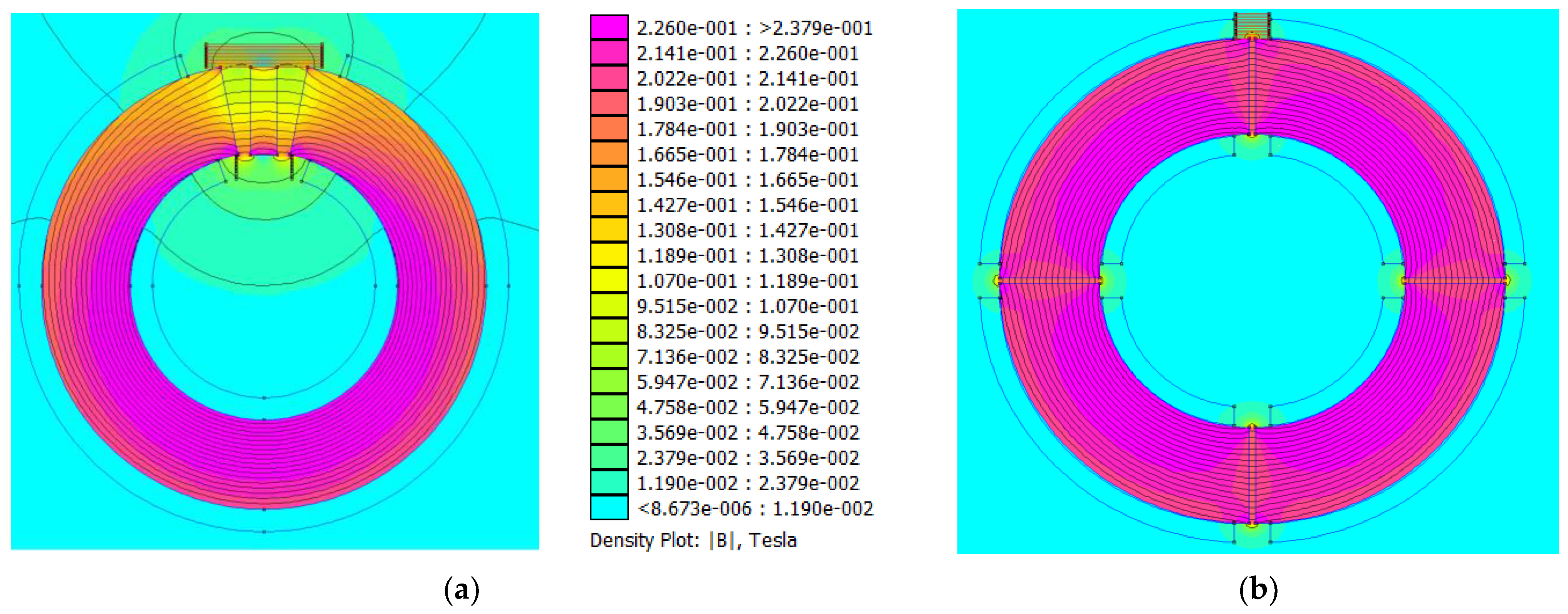
Using the simulation program FEMM 4.2, which works on the principles of finite element methods, both discussed situations of the E-shape core were analyzed, while the focus was given to the magnetic flux distribution. The cores of the inductors were saturated with the same current, while the number of turns was the same for analyzed alternatives. For the first alternative, one air gap located on the middle column of the core was considered. The second case considered distributed air gap presented by four smaller air gaps so that the inductance and thus the same magnetic flux in the core was maintained (Figure 4).
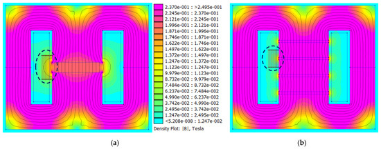
Figure 4.
Comparison of the magnetic flux distribution within the magnetic circuit of an inductor with E-core for (a) one air gap and for (b) distributed air gap.
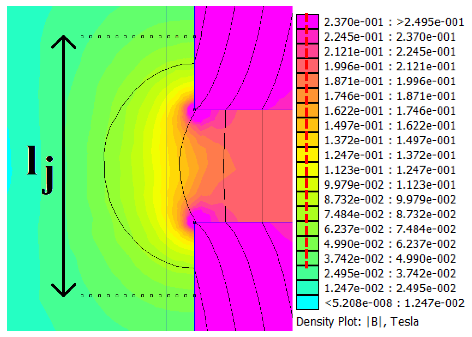
The evaluation of magnetic field distribution around the air gaps of analyzed solutions was performed for a certain area of the air gap (distance from the air gap and length along the air gap). This is represented by the situation shown in Figure 5. Consequently, a comparison of the amplitudes of magnetic induction within the analyzed area is graphically interpreted in Figure 6 for one air gap situation and in Figure 7 for a distributed air gap.
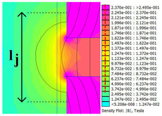
Figure 5.
Graphical interpretation of the evaluation of magnetic induction around the space of core air gap.
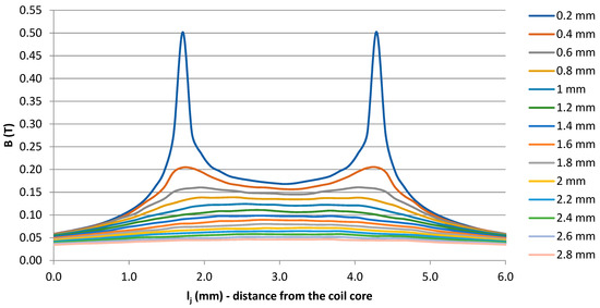
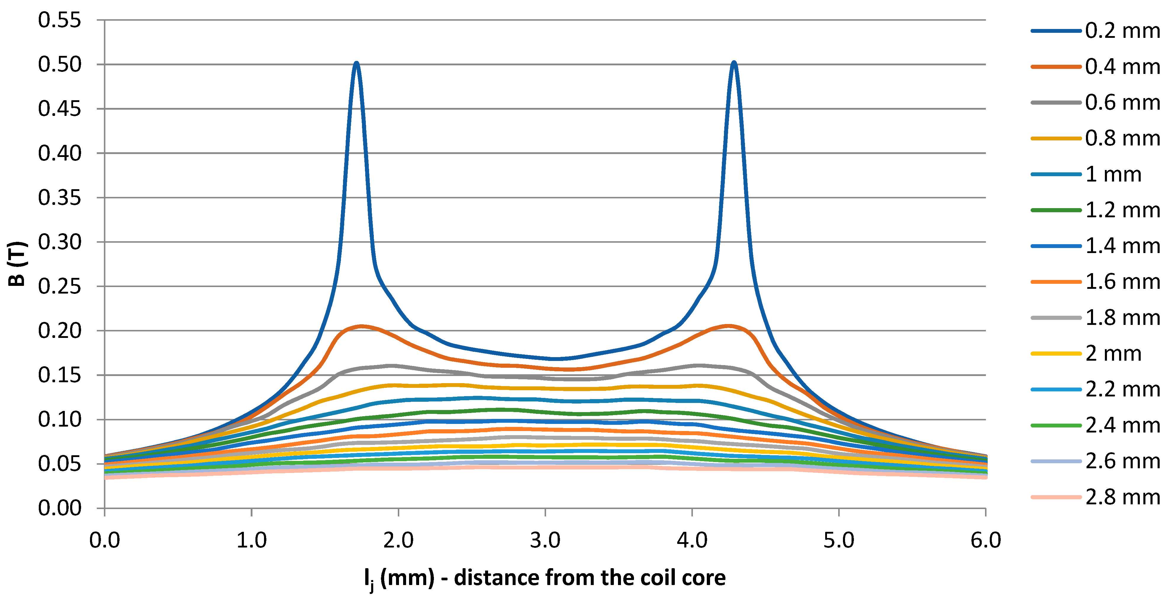
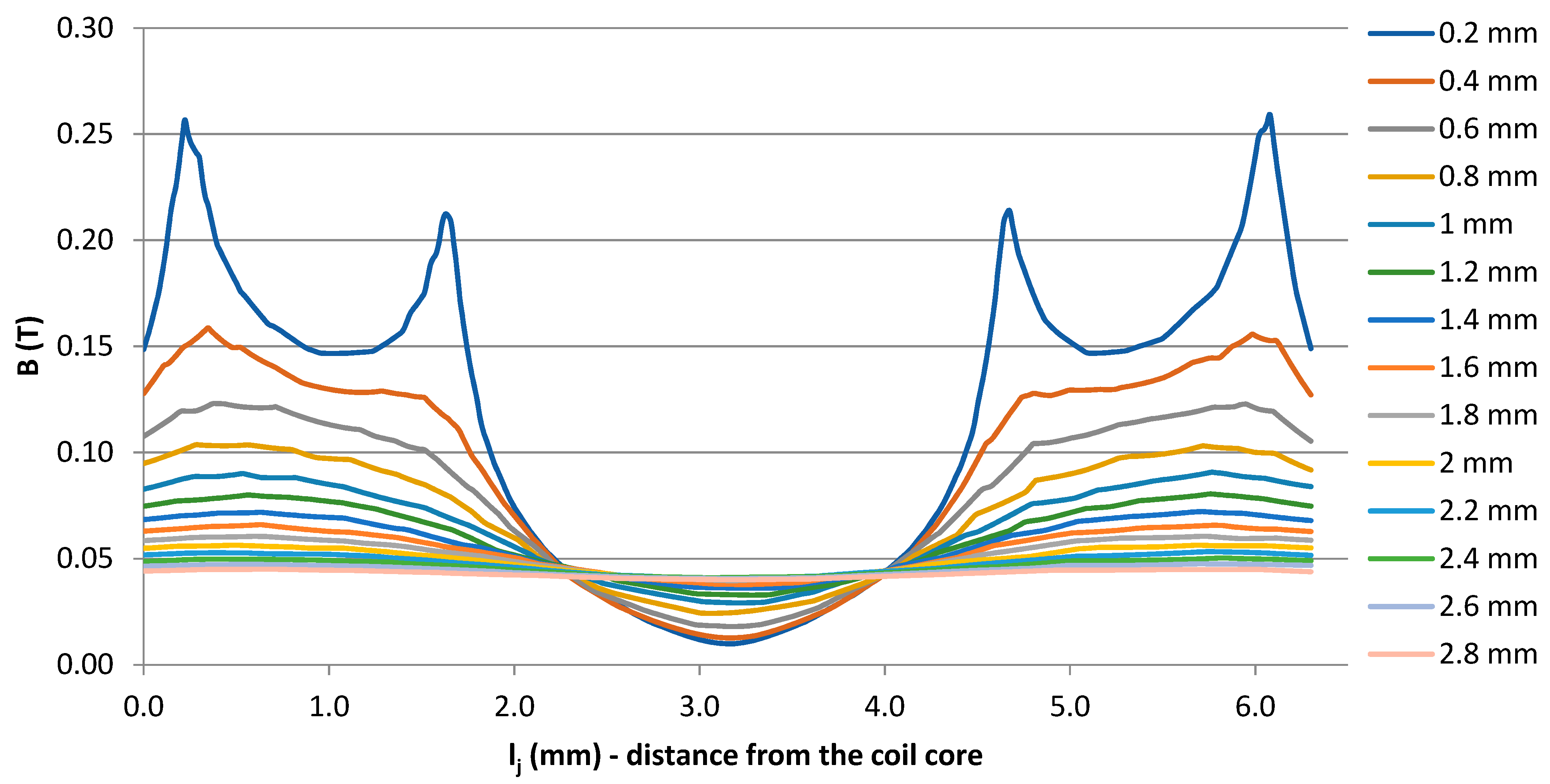
Figure 6.
Magnetic induction distribution in dependency on the distance from the air gap and the length along the airgap for inductor described by situation Figure 4a.

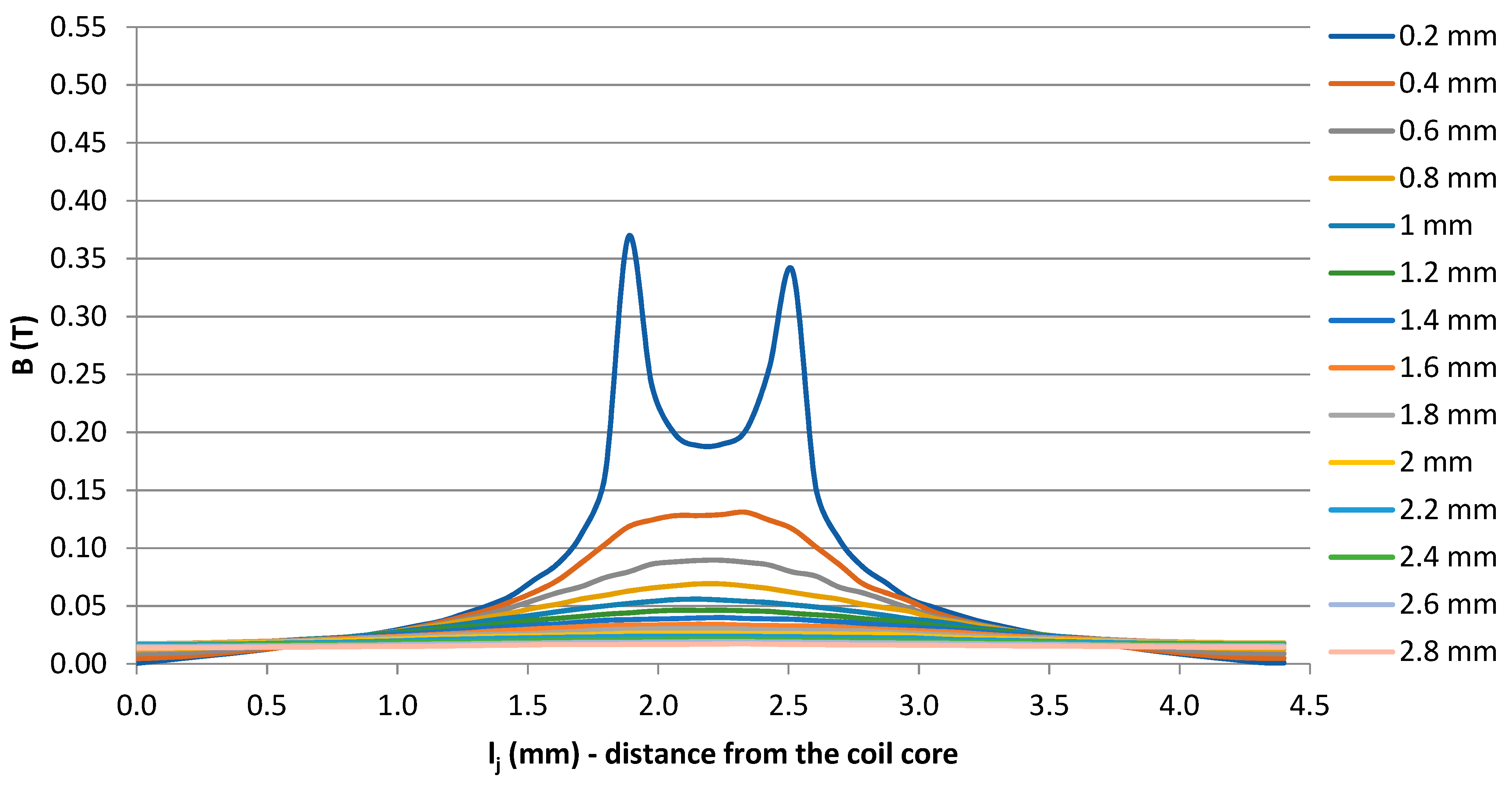
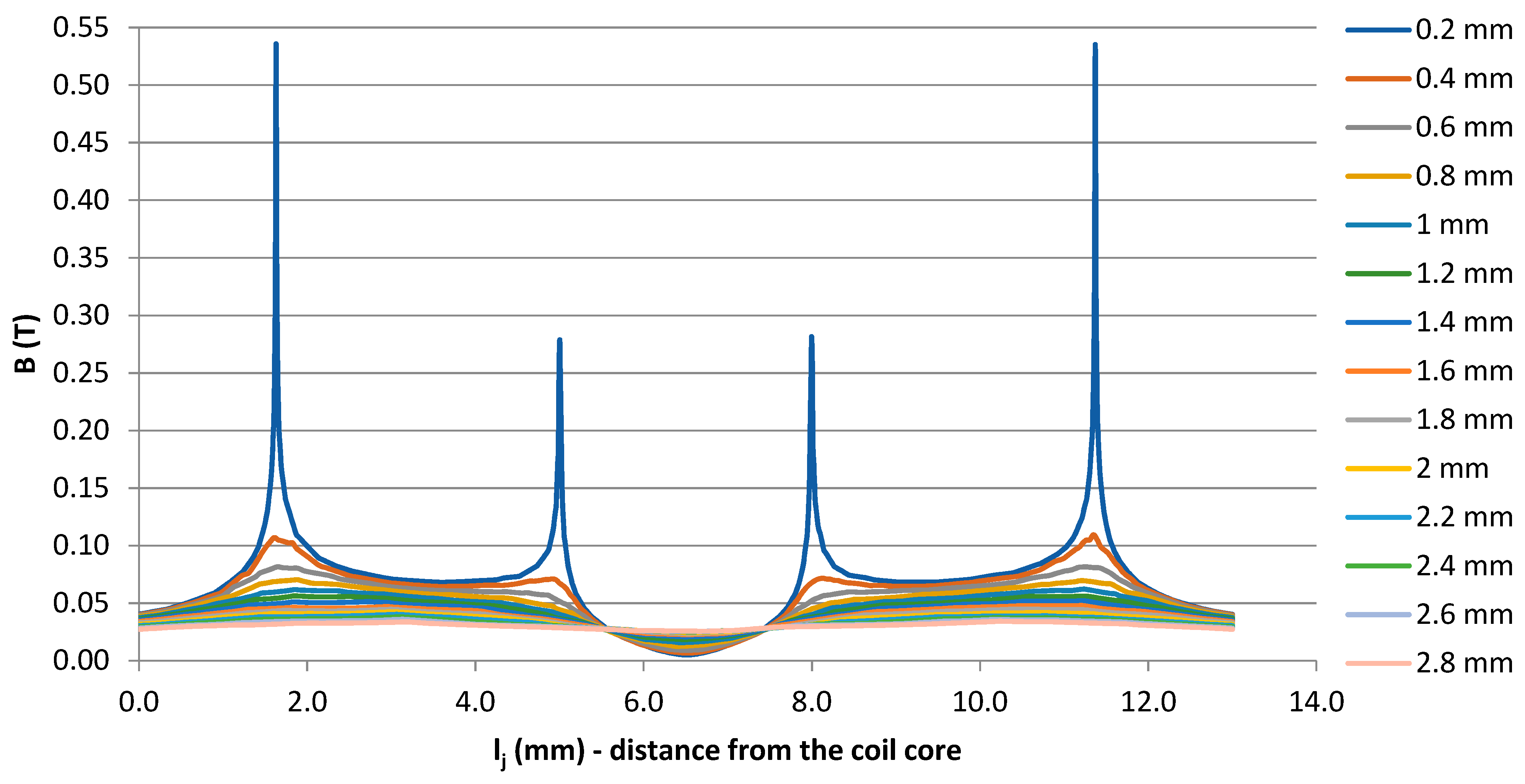
Figure 7.
Magnetic induction distribution in dependency on the distance from the air gap and the length along the air gap for inductor described by situation Figure 4b.
As described above, the evaluation of induction took place longitudinally to the core. Figure 5 as an example indicates a red line connecting the measurement points, while this line is located at 0.4 mm from the core towards the winding. Thus, the legend of these simulation images is the distance of the measuring lines from the core.
Figure 6 shows that at 1.8 mm from the core where the first coil winding layer was expected to be located, the value of induction was approximately 160 mT. It should be noted that the distance of 1.8 mm was the limiting distance for windings around the air gap. From the results presented for distributed air gap (Figure 7), it is seen that for the same distance from the core, the induction was 80 mT, which is half the value of the first coil alternative.
2.2. Experimental Verification of Fringing Flux Suppression—Delimitation of the Space around Airgap
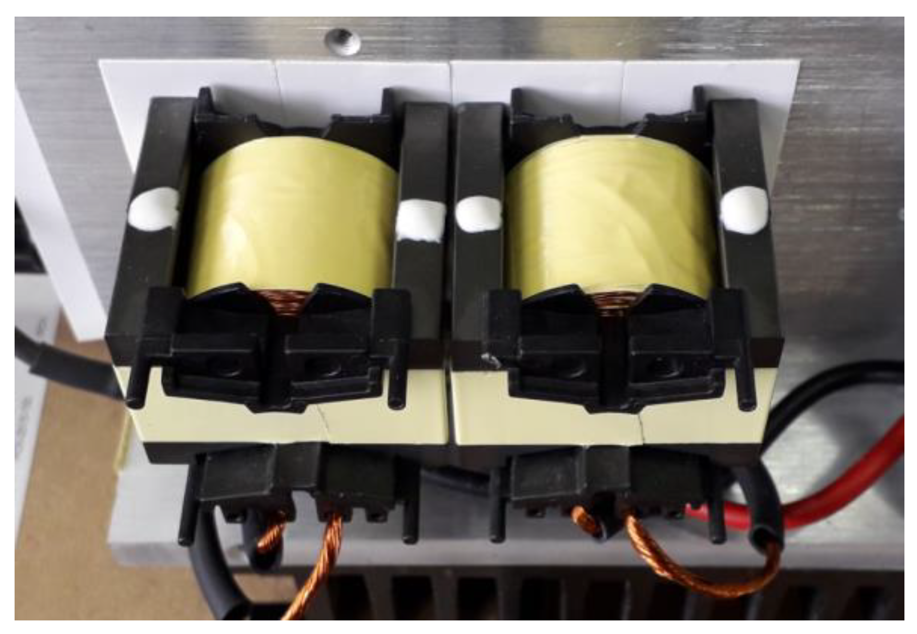
After a previous discussion about the possibilities of fringing flux suppression, the experimental verification was realized. As was mentioned, the consequence of fringing flux is the generation of the eddy currents which increases the losses and thus the thermal performance of the coil´s winding. The experiments were therefore oriented on evaluation of the thermal performance of the analyzed coil’s air gap alternatives, operated under nominal conditions of power factor correction (PFC) converter. The interleaved step-up converter operating as a PFC had an input voltage of 3 × 120 V (L-L), an output voltage of 480 V, and an output power of 4 kW. Table 1 lists the main properties of the inductor, while Figure 8 shows practical application within the heatsink of the converter. The figure shows two inductors, while PFC is of the interleaved type. Both alternatives were prepared, i.e., inductor with one air gap located in the center of the core (Figure 4a) and with one centered air gap but excluded (Figure 2).

Table 1.
Main parameters of PFC inductor v1 for the case study of delimitation of the space around airgap.
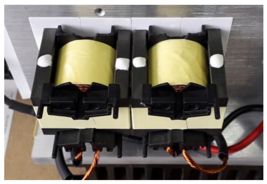
Figure 8.
Practical realization of PFC inductor v1 for experimental verifications.
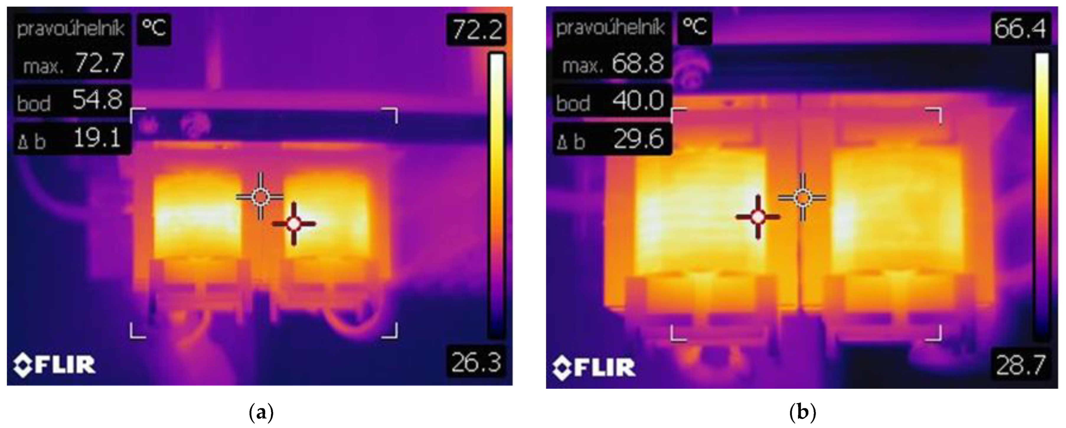
Figure 9 shows the temperature distribution results for both investigated alternatives of air gap type. The left side refers to the result for the core with one centered air gap. If temperature field distribution is analyzed, it is seen that the maximum value was located around the space, where the air gap was concentrated, while the value reached 72.7 °C (temperature of the winding). During infrared measurements, the temperature of the core was also evaluated, while from Figure 9 left is seen that its value approached 54.8 °C. For the case with excluded space around the air gap, Figure 9 right should be observed. It is apparent that the winding temperature decreased to 68.8 °C, while the temperature of the core dropped to 40 °C. Based on these results, it is evident that the effect of air gap modification on the temperature performance was significant while winding temperature dropped by more than 5% and the temperature of the core dropped by 27%. Therefore, the effect of fringing flux was suppressed as well.
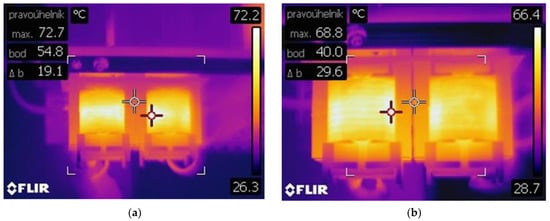
Figure 9.
Temperature distribution during converter PFC operation at nominal power equipped with (a) inductor with one centered air gap, (b) inductor with excluded space around air gap.
2.3. Analysis of the Fringing Flux Suppression on Toroid Ferrite Core—Airgap Distribution
Another experiment we conducted was the effect of the distributed air gap. Table 2 lists the main properties of the PFC inductors used for this experiment. We focused on the identification of the magnetic field reduction (FEM analysis), and a later experiment related to inductance stability was performed.
Table 2.
Parameters of PFC inductor v2 for analysis of distributed airgap influence.
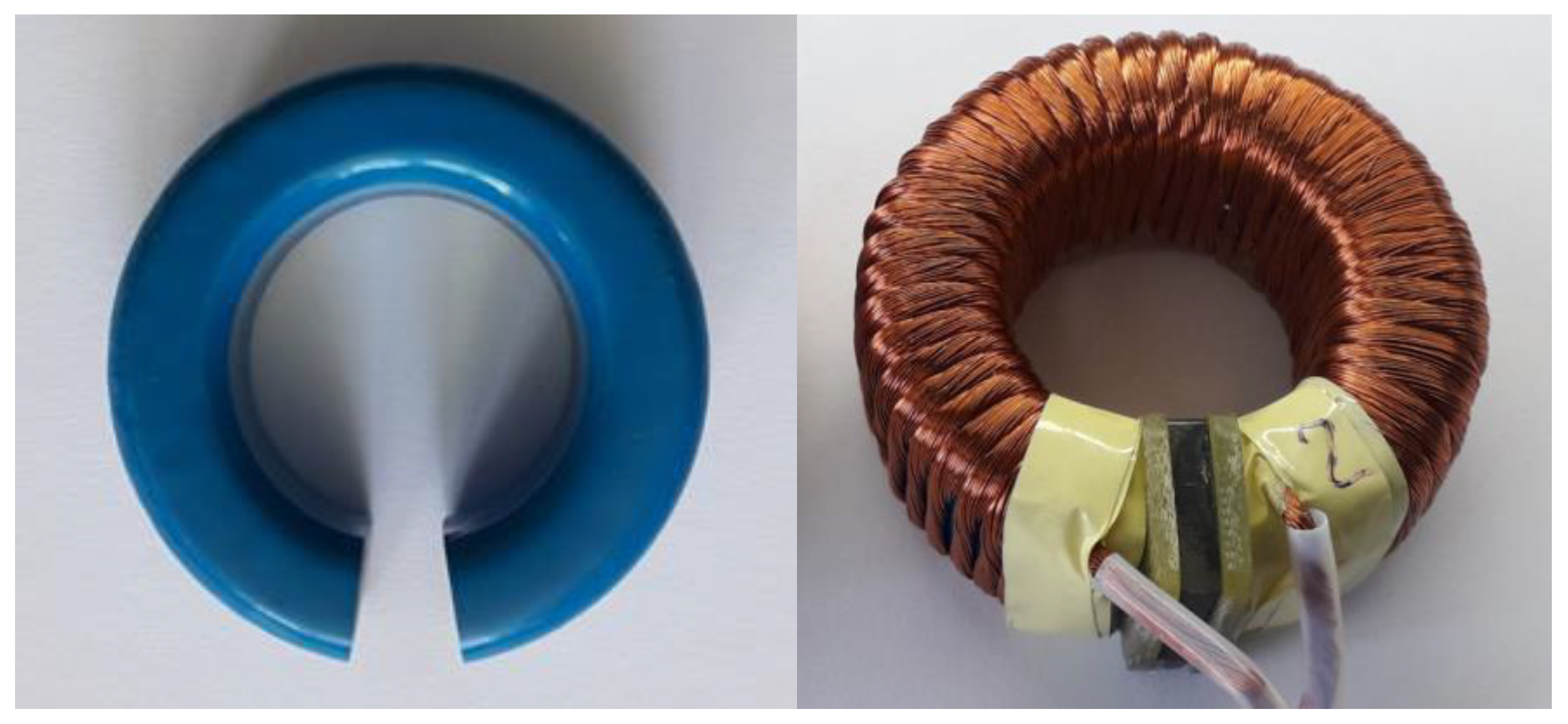
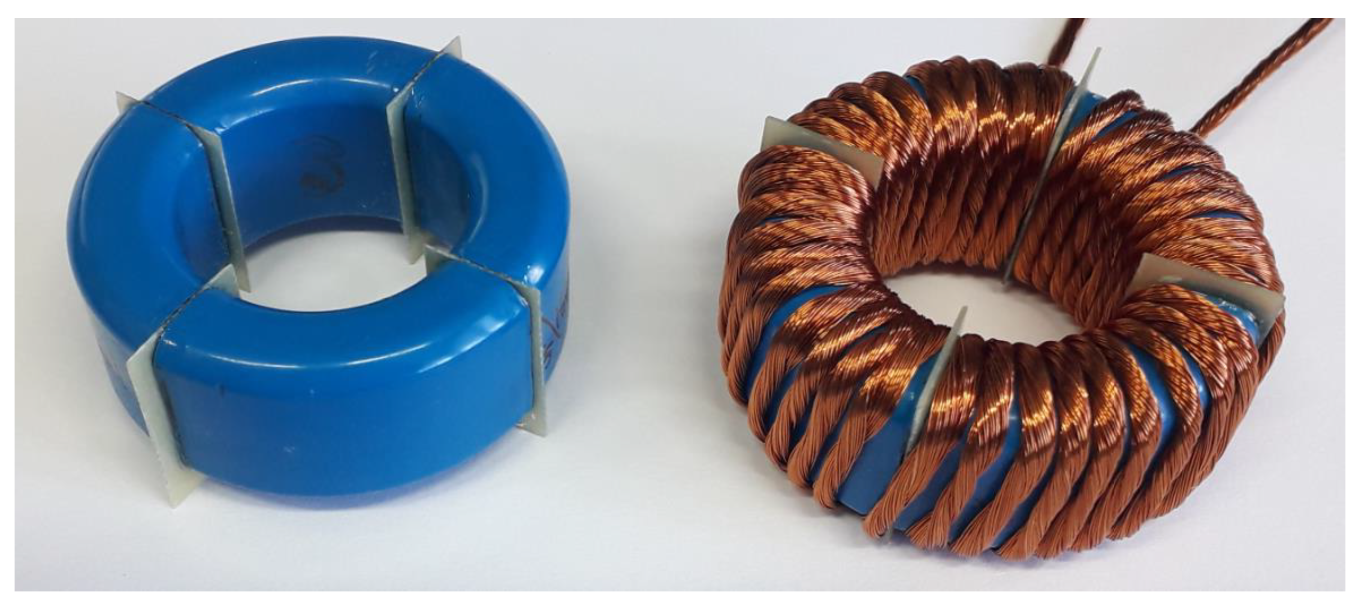
Two alternatives of inductor design made on toroid core were analyzed. The first alternative was made in the way of an inductor made on a gapped core, while the division of this gap (shortening) was performed by insertion of two non-conductive plates (FR4) and magnetically conductive material placed between these plates (Figure 10). This way, the air gap was distributed, but not evenly within the inductor volume. Therefore, the second alternative was made with distributed air gaps with smaller dimensions distributed moderately around the perimeter of the core (Figure 11).

Figure 10.
Alternative of the toroidal inductor with air gap given by product type (left) and modification by shortening airgap by ferrite material inserted within air gap (right).

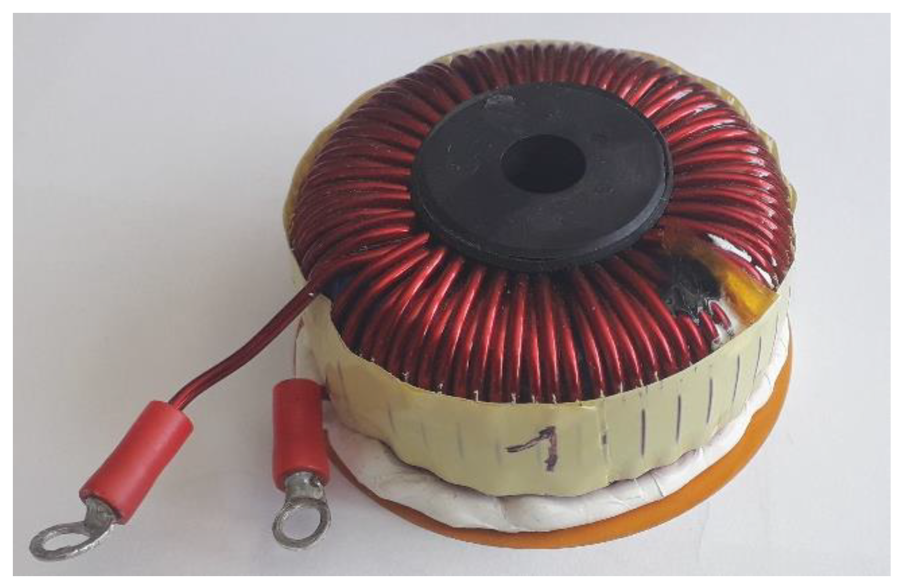
Figure 11.
Alternative of the toroidal inductor with the distributed air gap without winding (left) and with winding (right).
The analysis of the magnetic field distribution for v2 inductor alternatives was performed once using the simulation program FEMM 4.2. For the first alternative (delimitated space around air gap), the results are shown in Figure 12 left, while the highlighted areas indicate the evaluation points of magnetic induction. Figure 12 right refers to the situation with distributed air gap, whereby evaluation points are indicated around one of the air gaps of the core.
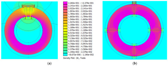
Figure 12.
Comparison of the magnetic flux distribution within the magnetic circuit of an inductor with toroidal core for (a) delimitated air gap, (b) distributed air gap.
Figure 13 and Figure 14 show results of the magnetic induction amplitudes within the selected space of the air gap for the inductor within one air gap filled with magnetically conductive material (see Figure 12a). For this case, two surroundings were evaluated, i.e., the area on the outer and inner diameter of the core. Results valid for the area on the outer diameter are shown in Figure 13. Here it is seen that the peak values of the magnetic induction were located at the edges of the magnetic core as well as on the edges of inserted magnetically conductive material.
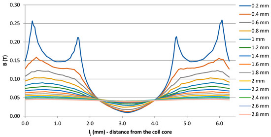
Figure 13.
Magnetic induction distribution along the outer diameter of the air gap of the inductor described by situation Figure 12a.
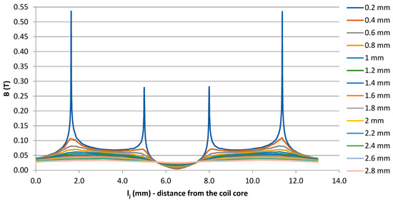
Figure 14.
Magnetic induction distribution along the inner diameter of the air gap of the inductor described by situation Figure 12a.
Evaluation of the values of magnetic induction on the inner diameter of the air gap was provided as well, while the results are graphically interpreted in Figure 14. Similar to the previous case, the highest values were present on the edges (boundaries) between air gap and core or magnetically conductive material. Moreover, comparing results in Figure 14, it is seen that the peak value of magnetic induction was two times higher for the closest vicinity of the evaluation field (0.2 mm). Above this value, the intensity of the magnetic induction around the airgap was similar comparing the inner and outer parts.
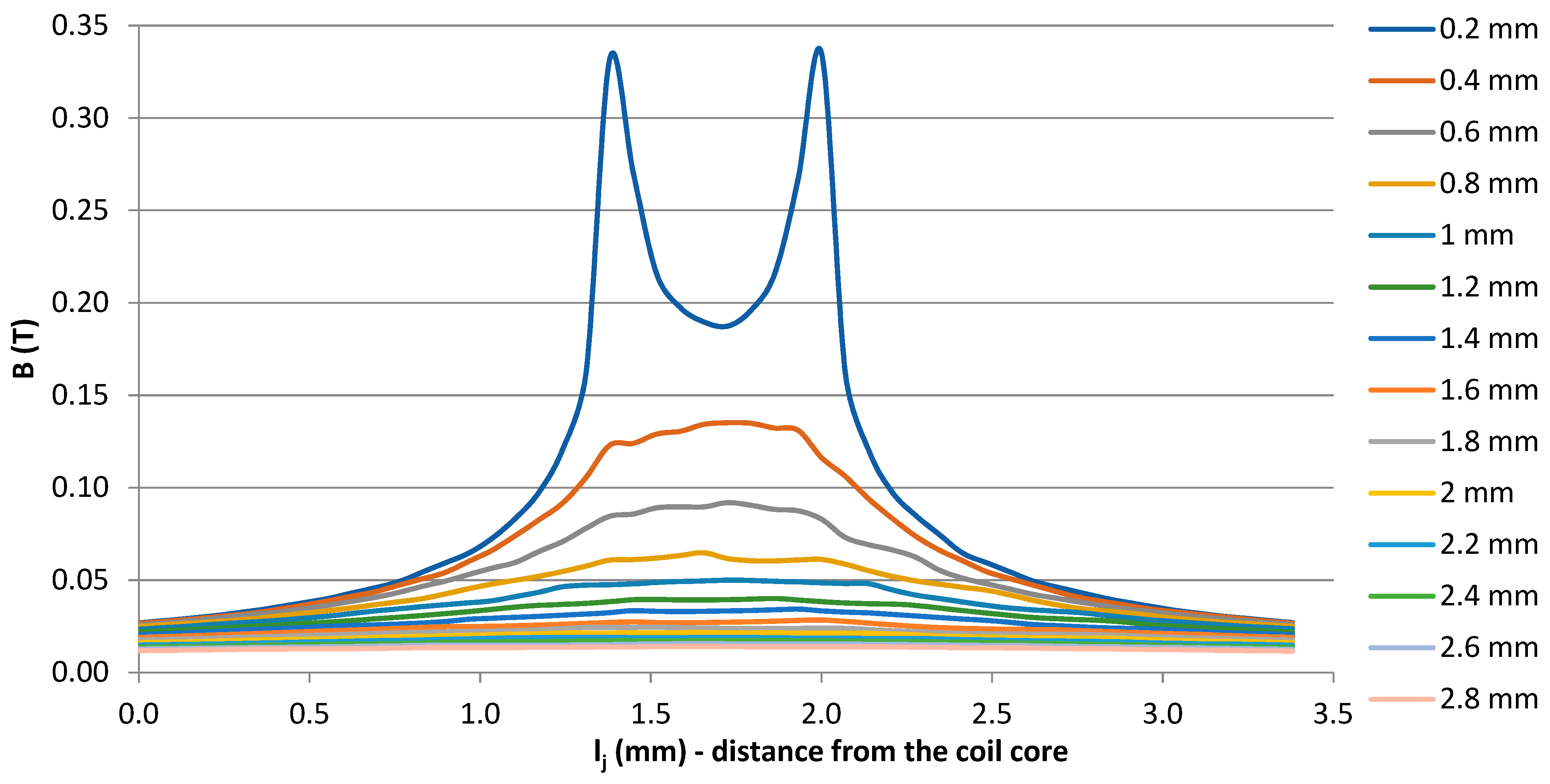
Figure 15 shows the evaluation of the magnetic induction amplitudes within the area of one of the airgaps for the situation of the magnetic core shown in Figure 12b, i.e., for the inductor with the distributed air gap. In this situation, the air gap was similar for inner and outer diameter, therefore only the outer part was evaluated. The maximum was visible for the closest evaluation field (0.2 mm), while later it is seen that the amplitudes were reducing. For example, if the evaluation field in the distance of 2 mm is considered, then from Figure 14 and Figure 16 we can see that the resulting amplitude of the fringing flux in the case of the distributed air gap was lowered by more than 50% (0.11 T for an inductor with one airgap, 0.06 T for an inductor with distributed airgap).
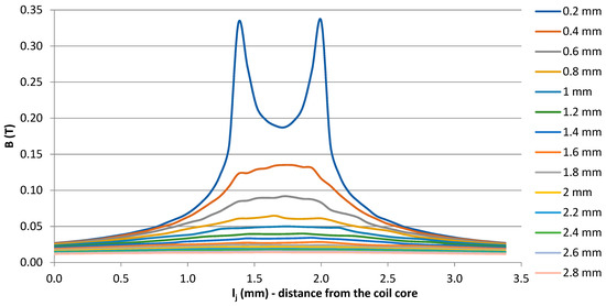
Figure 15.
Magnetic induction distribution along with one of the distributed air gaps of the inductor described by situation Figure 12b.
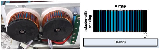
Figure 16.
Practical realization of PFC inductor v2 for experimental verifications (left) and demonstration of the evaluation of the inductance value stability (right).
3. Influence of the Conductive Non-Magnetic Material on the Inductor Parameters
Concerning the analyses of the fringing flux generation from previous experiments, the side effect of the type of the air gap can be once reflected within the stability of the value of inductor inductance. This effect can be observed when the additional cooling system is placed across the inductive component. The experimental investigation of this effect was realized by laboratory measurements, while the value of inductance was measured in dependency on the distance from the aluminum heatsink (Figure 16 and Figure 17). As a heatsink, the aluminum plate was used where the inductors were pressed through an insulating pad against the aluminum heatsink. During the measurements, we observed the effect of the distance of the inductor from the aluminum plate on the inductance value. In this way, the dependency of the stability of inductance value was performed for both inductor types (Figure 11 and Figure 12).
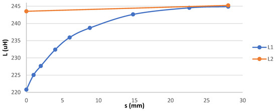
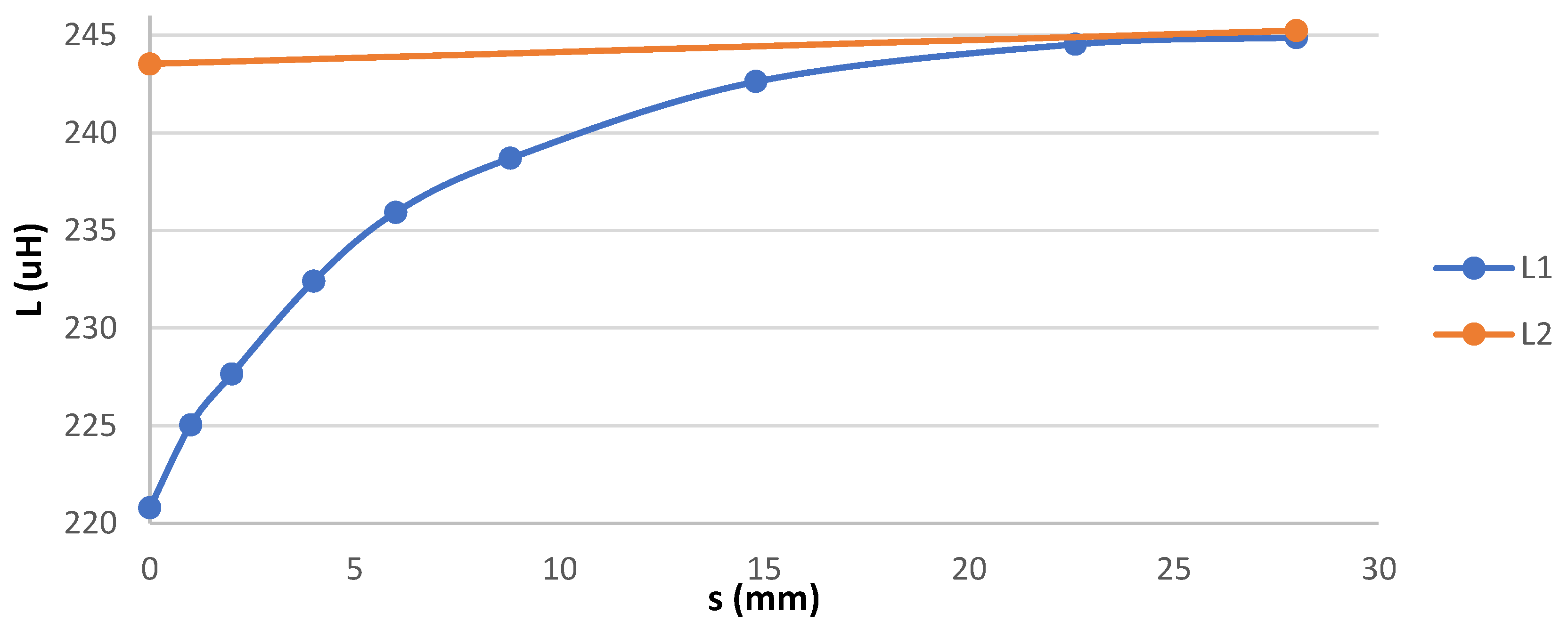
Figure 17.
Value of inductance for evaluated inductors in dependency on the distance from the heatsink.
The results from the measurements are reported in Figure 17. Two types of inductors were tested, i.e., L1 referring to Figure 10 and L2 referring to Figure 11. It can be seen that the influence of the heatsink on the value of inductance considering shorted airg ap of the inductor was significant. The inductance value of the coil when it was closest to the aluminum plate was approximately 220 μH and after moving to a distance of 3 cm, the inductance of the coil increased to 245 μH. In contrast, the coil with distributed small air gaps showed a significantly lower dependence of the inductance value on the distance from the heatsink. This is confirmation of the side effect of fringing flux, i.e., more care must be taken in the case when the inductor of the switching power supply needs an additional heatsink. The heatsink behaves like a conductor in which eddy losses are generated due to magnetic flux (induction), which impairs the efficiency of the entire power supply. Thus, the heatsink behaves in part as a shorted winding turn, resulting in a reduction of the inductance value as the distance from the heatsink decreases.
4. Practical Optimization of PFC Converter Using Analyzed Magnetic Components
The converter on which the proposed optimizations will be made is represented by a three-phase PFC converter (Figure 18), which is designed for industrial applications. The converter topology is a dual interleaved boost converter. The main parameters are listed in Table 3, while it is seen, that the non-optimized solution was equipped with the inductor made on alloy core, operated at 41 kHz (Figure 19). At this point, it must be discussed that the optimization process is focused on the possibilities of the increase of switching frequency together with efficiency to allow possible volume reduction.
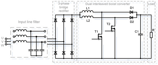
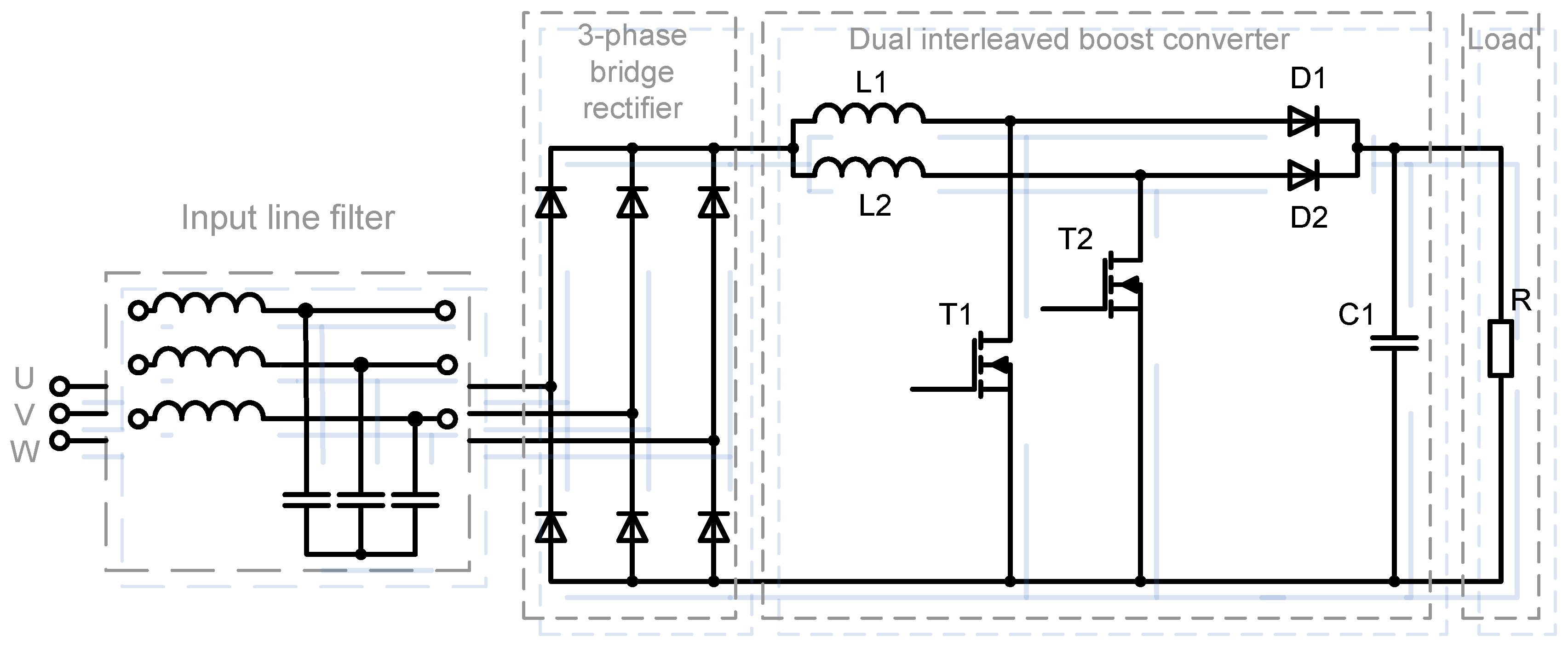
Figure 18.
Principal schematic of PFC converter used for evaluation purposes.
Table 3.
Parameters of PFC converter used for experiments.
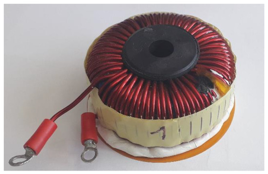
Figure 19.
Original alloy core inductor used within optimized PFC converter used for referenced measurements.
4.1. Performance Evaluation with Standard Alloy PFC Inductor
Initial measurements were done in the way of efficiency evaluation in dependency on the value of output power, while the original inductor made on alloy core was used. The efficiency investigation was also done for higher switching frequencies to identify shortcomings associated with the non-optimized inductor solution.
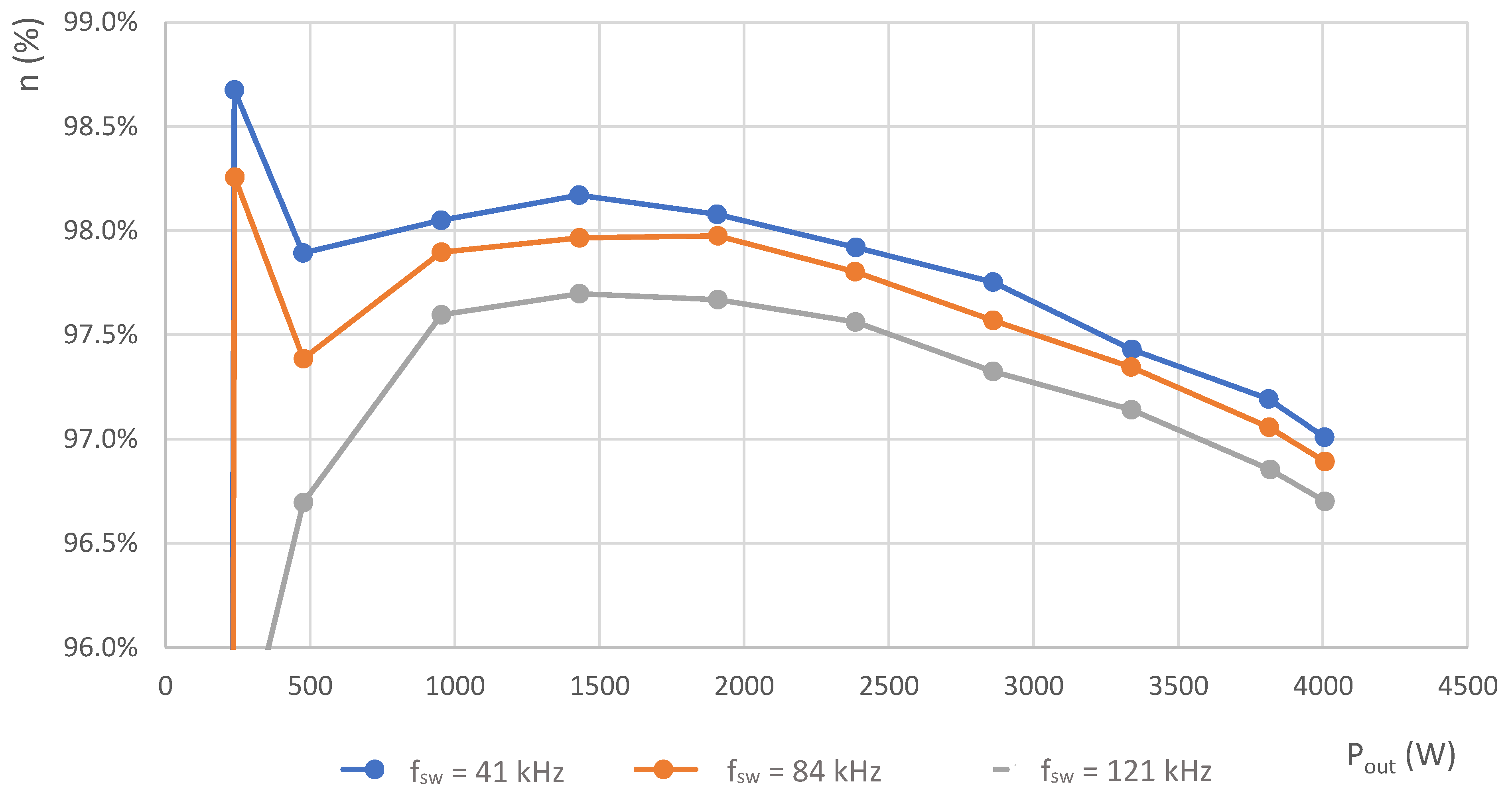
By increasing the frequency, we can assume that the losses increase not only on the transistors and diodes but also on the coils. As is stated within the theory of alloy cores, their practical applicability is up to 100 kHz due to a significant increase in losses in the core at higher frequencies [15,16,17]. Considering the inductance of the coil, as the frequency increases, the current ripple decreases, thus the increase in losses is partially compensated. As a consequence, reduction of the core saturation caused by the AC part will be reduced. Considering the results shown in Figure 20, the efficiency drop for 80 kHz of switching frequency is not critical, thus evaluation for 120 kHz was provided as well.
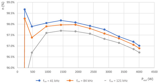
Figure 20.
Efficiency waveform in dependency on the output power of converter (alloy core inductor).
At 120 kHz switching frequency, a decrease in efficiency of 0.3% was recorded, which represents a difference of 13 W compared to 41 kHz operation.
4.2. Performance Evaluation with Optimized Ferrite Inductors with Delimitated Space around Air Gap
To improve efficiency, within the next step we proceeded to replace the original alloy core coils with ferrite core coils. The first alternative reflects PFC inductor v1 optimization. It was made on the PQ35/35 core (Figure 8) and its parameters are described in Table 1. Inductor was made with delimitated space around the air gap, thus reduction of the fringing flux and consequently reduction of power losses were expected. From the study of the effect of fringing flux, it was observed that one of the disadvantages of multilayer winding was the generation of proximity effect. Therefore, an additional analysis of the effect of the inductive components was performed by using an inductor made on a ferrite core with one winding layer. The second alternative of PFC inductor was reflecting optimized design on toroidal core, i.e., v2 PFC inductor with unevenly distributed air gap using ferrite material (Figure 10).
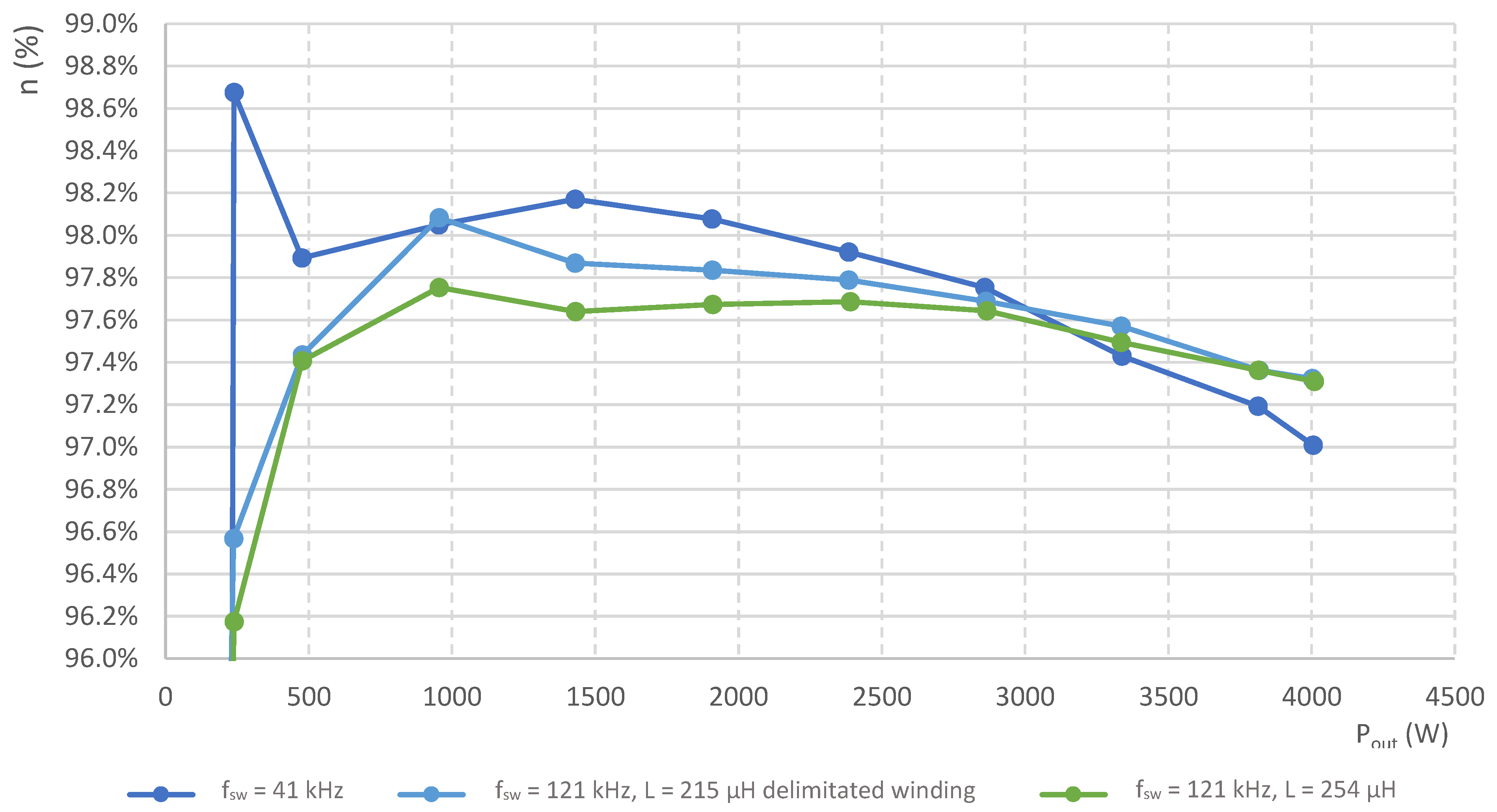
The measured efficiencies for both cases were compared to the efficiency of the original PFC converter solution, and the results are interpreted in Figure 21. It is clear from the graphs that the efficiency was 0.3% better than the original configuration, which represents a difference of approximately 13 W.

Figure 21.
Comparison of the efficiency performance in dependency on the output power of converter for original and optimized cases of power inductors.
When analyzing the efficiency results of an optimized coil converter made with an unevenly distributed shortened air gap, it is clear that the efficiency of the PFC converter with these coils was lower than expected, which probably resulted in increased losses—increase in core volume but also due to increased current ripple [3,20]. This could be due to the effect of the aluminum heatsink, which was close to the coils (Figure 16), reducing their inductance. The further decrease in efficiency was probably due to the eddy currents that arose in the aluminum heatsink around the relatively large air gap of the coil and thus increased the current consumption of the entire converter.
4.3. Performance Evaluation for High-Frequency Operation Using Inductors with the Distributed Airgap
One of the possible goals for this study is demand for a further increase of the switching frequency to 200 kHz. As mentioned above, the relatively large air gap in the coil has its drawbacks, so it should be replaced with a coil that has a distributed air gap. However, the condiction for switching frequency increase is reflected in the corresponding value of inductance. For this purpose, two alternatives from Figure 11 with a lowered number of turns were realized, thus achieving an inductance value of 165 μH and 200 μH.
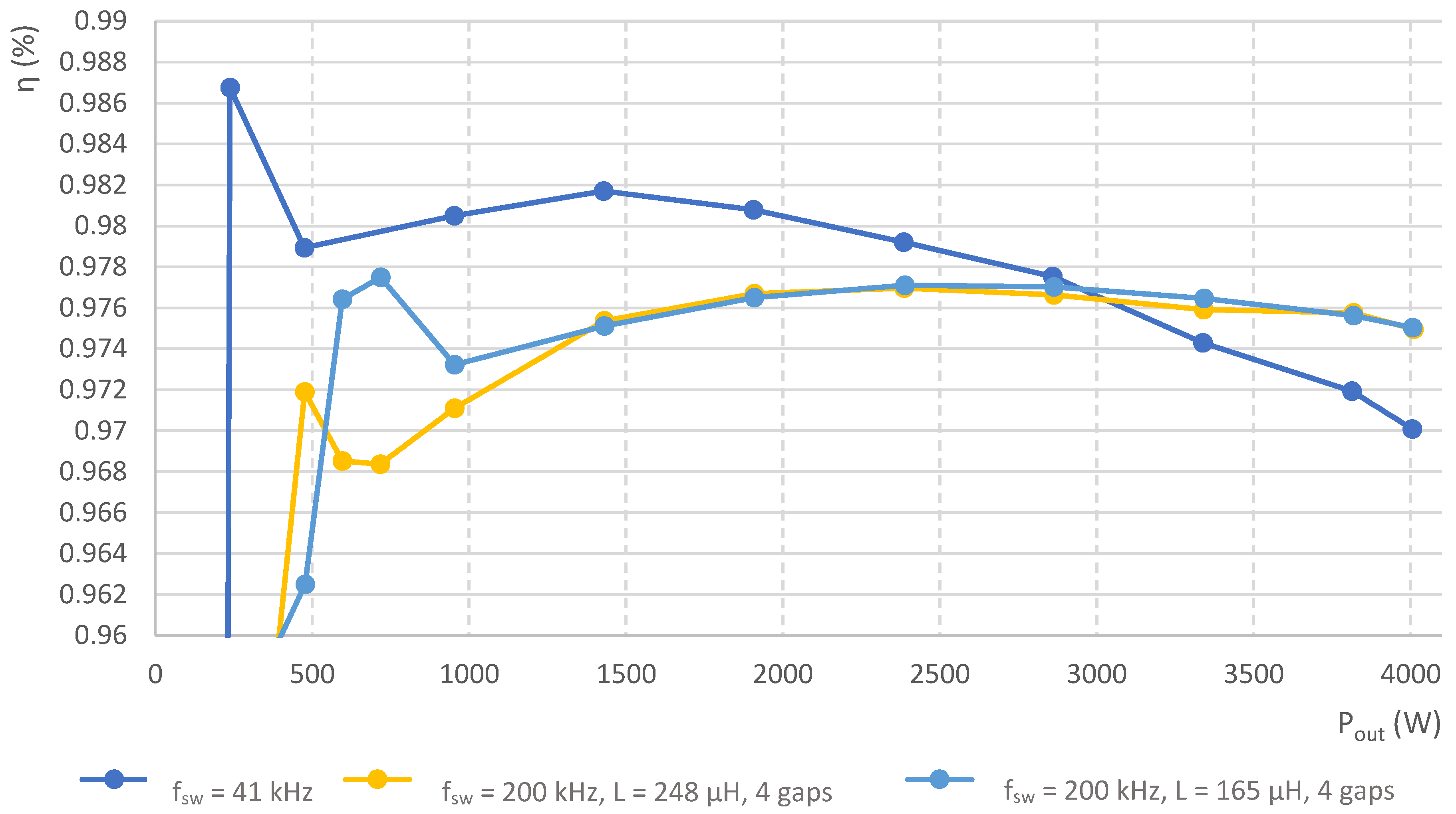
From Figure 22 we can see that the efficiency for both coil values improved by almost 0.1% compared to the original situation, which represents a difference of about 3 W. This is valid for the nominal operational power. For the lowered power delivery, the efficiency of the original solution was higher, but on the other hand, it must be stated here that the switching frequency was 5 times lower. In principle, presented experimental measurements declare that with the use of optimized inductive components, it is possible to improve efficiency together with power density as well [20,21,22].
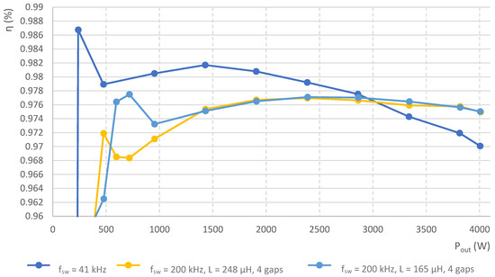
Figure 22.
Comparison of the efficiency performance in dependency on the output power of converter for original inductor and inductors with the distributed air gap.
5. Conclusions
In this study, the investigation of the influence of fringing flix on the operational frequency of the PFC converter was evaluated, together with an experimental analysis of the construction of magnetic components reflecting suppression of the fringing flux effect. For the developed PFC converter, the alternatives of power inductors were designed, while the focus was to observe optimization of the operational parameters of the converter. Dealing with the fringing flux effect, when delimitated air gap of the magnetic core was provided, the suppression of the eddy current effect was achieved, which was reflected in better thermal performance of the component. It was also found that with proper distribution of the inductor air gap, the higher stability of the inductance value was achieved as well. Based on the results, it was found that the fringing flux effect was also dependent on the arrangement of the winding, while one-layer winding provided better eddy current suppression compared to multi-layer windings. Various alternatives of power inductor design were experimentally verified during the investigation of the efficiency performance of the PFC converter. The original design utilized alloy core inductors and operation was defined for 41 kHz of switching frequency. With the optimized alternatives of power inductors (delimitated airgap), better performance was achieved considering efficiency values, while the operational frequency was increased in the first experiment by up to 3 times. For nominal operation (4 kW) of PFC, the efficiency increase was 0.5%. Consequently, other experiments were carried out considering distributed airgap, for which the main goal was to achieve higher operational frequencies (200 kHz) and to maintain high-efficiency performance. Compared to the original design, the efficiency increase was 0.5%, whereby a 5-times-higher operational frequency enabled to significantly reduce component sizes.
Author Contributions
Conceptualization, M.F.; methodology, M.P.; formal analysis, M.Z.-M.; writing—original draft preparation, D.A.; writing—review and editing, M.F.; visualization, supervision, M.Z.-M.; funding acquisition, M.F. All authors have read and agreed to the published version of the manuscript.
Funding
This research was funded by National Grant Agency Vega, grant number 1/0063/21, and by National Grant Agency APVV for project funding APVV-20-500.
Institutional Review Board Statement
Not applicable.
Informed Consent Statement
Not applicable.
Data Availability Statement
Not applicable.
Acknowledgments
The authors wish to thank for the support to the National Grant Agency Vega, grant number 1/0063/21 and by National Grant Agency APVV for project funding APVV-20-500.
Conflicts of Interest
The authors declare no conflict of interest.
References
- The Effects of an Air Gap in Magnetics. Available online: https://www.cettechnology.com/the-effects-of-an-air-gap-in-magnetics/ (accessed on 20 April 2022).
- Huang, X.; Chen, W. An Improved Calculation Method of High-Frequency Winding Losses for Gapped Inductors. J. Inf. Hiding Multimed. Signal Process. 2017, 9, 751–759. [Google Scholar]
- McLyman, C.W.T. Transformer and Inductor Design Gandbook; CRC Press: Boca Raton, FL, USA, 2017; ISBN 9781439836880. [Google Scholar]
- Okilly, A.H.; Baek, J. Optimal Design Analysis with Simulation and Experimental Performance Investigation of High-Power Density Telecom PFC Converters. Appl. Sci. 2021, 11, 7911. [Google Scholar] [CrossRef]
- Evaluating Fringing Effects in Multi-Gapped Toroids. Available online: https://eepower.com/technical-articles/evaluating-fringing-effects-in-multi-gapped-toroids/# (accessed on 20 April 2022).
- Jung, J.-H.; Choi, J.-M.; Kwon, J.-G. Design Methodology for Transformers Including Integrated and Centertapped Structures for LLC Resonant Converters. J. Power Electron. 2009, 9, 215–223. [Google Scholar]
- Szczerba, P.; Raczko, W.; Ligenza, S.; Worek, C. Analytical design optimization of PFC boost inductor in CCM. In Proceedings of the 21st International Symposium on Power Electronics (Ee), Novi Sad, Serbia, 27–30 October 2021; pp. 1–6. [Google Scholar] [CrossRef]
- Liu, Y.; Li, M.; Dou, Y.; Ouyang, Z.; Andersen, M.A.E. Investigation and optimization for planar coupled inductor dual-phase interleaved GaN-based totem-pole PFC. In Proceedings of the IEEE Applied Power Electronics Conference and Exposition (APEC), New Orleans, LA, USA, 15–19 March 2020; pp. 1984–1990. [Google Scholar] [CrossRef]
- Zou, J.; Wu, H.; Liu, Y.; Yang, L.; Xu, X. Optimal design of integrated planar inductor for a hybrid totem-pole PFC converter. In Proceedings of the 2020 IEEE Energy Conversion Congress and Exposition (ECCE), Detroit, MI, USA, 11–15 October 2020; pp. 1560–1564. [Google Scholar] [CrossRef]
- Kasikowski, R. Impact of the fringing effect on temperature distribution in windings and physical properties of toroidal ferrite inductors with a dual air gap. Meas. Autom. Monit. 2017, 63, 135–138. [Google Scholar]
- Sullivan, C.R.; Zhang, R.Y. Simplified design method for litz wire. In Proceedings of the Applied Power Electronics Conference and Exposition (APEC), Fort Worth, TX, USA, 16–20 March 2014. [Google Scholar]
- Tourkhani, F.; Viarouge, P. Accurate Analytical Model of Winding Losses in Round Litz Wire Windings. IEEE Trans. Magn. 2001, 37, 538–543. [Google Scholar] [CrossRef]
- Jez, R.; Polit, A. Influence of air-gap length and cross section on magnetic circuit parameters. In Proceedings of the 2014 COMSOL Conference, Cambridge, UK, 17 September 2014. [Google Scholar]
- Nussbaumer, T.; Raggl, K.; Kolar, J.W. Design guidelines for interleaved single-phase boost PFC circuits. IEEE Trans. Ind. Electron. 2009, 56, 2559–2573. [Google Scholar] [CrossRef]
- Ditze, S.; Ehrlich, S.; Weitz, N.; Sauer, M.; Aßmus, F.; Sacher, A.; Joffe, C.; Seßler, C.; Meißner, P. A High-Efficiency High-Power-Density SiC-Based Portable Charger for Electric Vehicles. Electronics 2022, 11, 1818. [Google Scholar] [CrossRef]
- Winkler, P.; Gunther, W. Using powder materials to replace airgaps for fringing flux reduction. In Proceedings of the International Exhibition and Conference for Power Electronics, Intelligent Motion, Renewable Energy and Energy Management, PCIM Europe, Nuremberg, Germany, 16–18 May 2017. [Google Scholar]
- Alabakhshizadeh, A.; Midtgård, O. Air gap fringing flux reduction in a high frequency inductor for a solar inverter. In Proceedings of the IEEE 39th Photovoltaic Specialists Conference (PVSC), Tampa, FL, USA, 16–21 June 2013; pp. 2849–2852. [Google Scholar] [CrossRef]
- Xu, H.; Chen, D.; Xue, F.; Li, X. Optimal Design Method of Interleaved Boost PFC for Improving Efficiency from Switching Frequency, Boost Inductor, and Output Voltage. IEEE Trans. Power Electron. 2019, 34, 6088–6107. [Google Scholar] [CrossRef]
- Kasikowski, R.; Wiecek, B. The reduction of fringing effect power loss in gapped ferrite inductors by changing the resistance and diameter of windings. In Proceedings of the 14th Quantitative InfraRed Thermography Conference (QIRT), Berlin, Germany, 25–29 June 2018. [Google Scholar]
- Ramos-Paja, C.A.; Saavedra-Montes, A.J.; Bastidas-Rodriguez, J.D. Co-Design of the Control and Power Stages of a Boost-Based Rectifier with Power Factor Correction Depending on Performance Criteria. Computation 2022, 10, 61. [Google Scholar] [CrossRef]
- Cacciato, M.; Consoli, A.; Crisafulli, V.; Vitale, G.; Abbate, N. A new resonant active clamping technique for bi-directional converters in HEVs. In Proceedings of the IEEE Energy Conversion Congress and Exposition, Atlanta, GA, USA, 12–16 September 2010; pp. 1436–1441. [Google Scholar] [CrossRef]
- Kindl, V.; Pechanek, R.; Zavrel, M.; Kavalir, T.; Turjanica, P. Inductive coupling system for electric scooter wireless charging: Electromagnetic design and thermal analysis. Electr. Eng. 2020, 102, 3–12. [Google Scholar] [CrossRef]


Publisher’s Note: MDPI stays neutral with regard to jurisdictional claims in published maps and institutional affiliations. |
© 2022 by the authors. Licensee MDPI, Basel, Switzerland. This article is an open access article distributed under the terms and conditions of the Creative Commons Attribution (CC BY) license (https://creativecommons.org/licenses/by/4.0/).