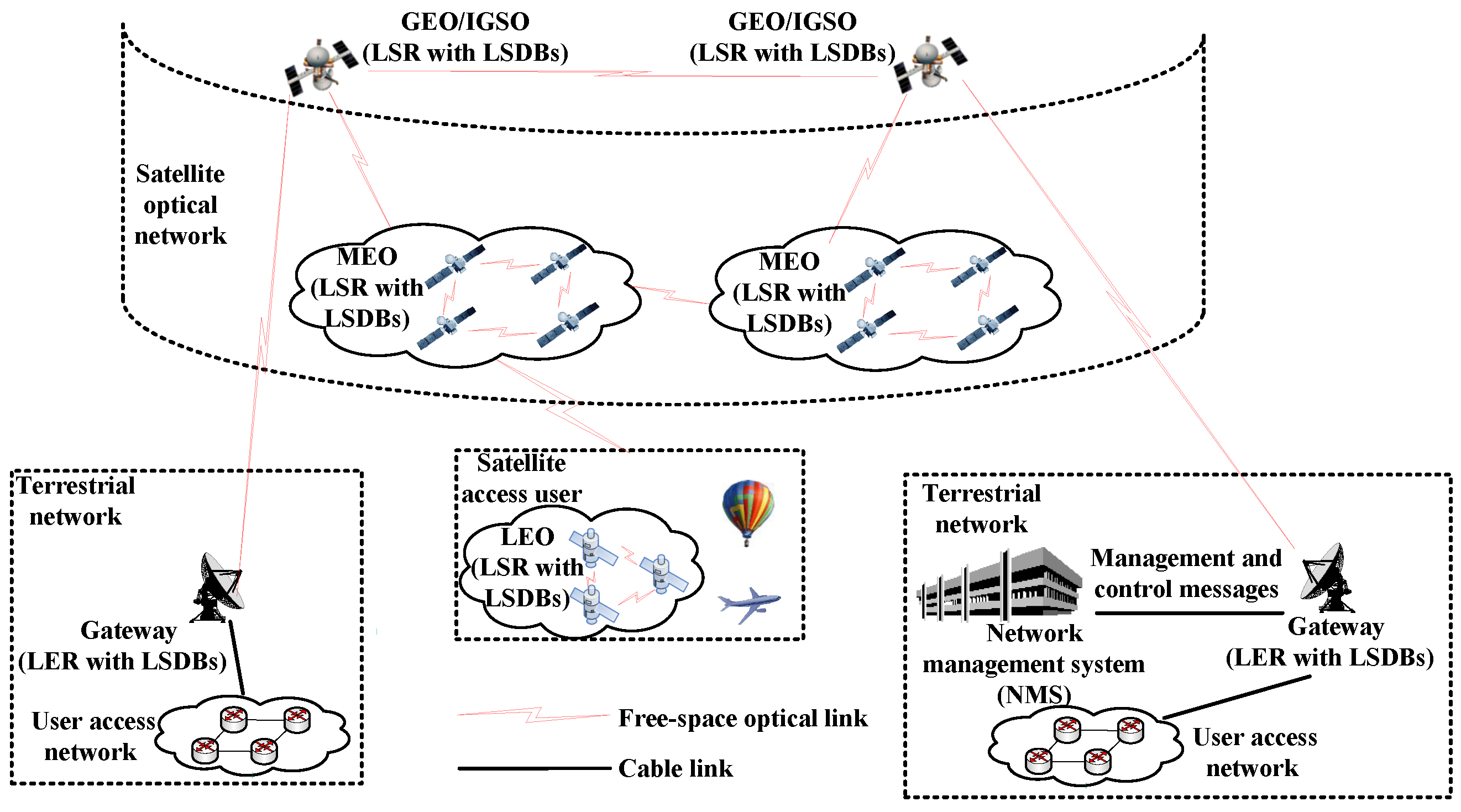
Article

Design and Implementation of Semi-Physical Platform for Label Based Frame Switching in Integrated Satellite Terrestrial Networks

1
School of Information and Communication, Guilin University of Electronic Technology, Guilin 541004, China
2
The 34th Research Institute of China Electronics Technology Group Corporation, Guilin 541004, China
3
State Key Laboratory of Information Photonics and Optical Communications, Beijing University of Posts and Telecommunications, Beijing 100876, China
4
Department of Electrical and Computer Engineering, University of New Mexico, Albuquerque, NM 87131, USA
5
The 54th Research Institute of China Electronics Technology Group Corporation, Shijiazhuang 050081, China
6
Hebei Key Laboratory of Photonics Information Technology and Application, Shijiazhuang 050081, China
*
Author to whom correspondence should be addressed.
These authors contributed equally to this work.
Appl. Sci. 2022, 12(13), 6674; https://doi.org/10.3390/app12136674
Submission received: 2 June 2022 / Revised: 25 June 2022 / Accepted: 28 June 2022 / Published: 1 July 2022
(This article belongs to the Collection New Trends in Optical Networks)

Abstract

:
With the explosion of traffic demand in recent years, the integration of satellite optical networks and terrestrial networks (ISTN) creates a promising networking solution for future low-latency, high-rate, and high-capacity communications. Owing to the high cost of deploying and maintaining a satellite optical network, it is critical to carefully design and plan the network to ensure the performance of the network. Thus, a semi-physical simulation platform based on software-defined networks (SDNs) is developed to simulate a satellite optical network and evaluate the performance of the proposed label-based advanced orbiting system (AOS) frame switching method that adheres to the Consultative Committee for Space Data Systems’ recommended standard (CCSDS). The semi-physical simulation platform has two major innovations: (1) adapting and integrating network protocols between the CCSDS and open system interconnect (OSI) reference models, particularly at the data link layer, and (2) the foundation for an SDN-based satellite optical network. In the control plane, real-time VxWorks Simulators serve as controllers to establish and manage various network protocols and the link manager protocol (LMP). Here, network protocols include open shortest path first (OSPF) for routing managing and controlling messages, constraint shortest path first–traffic engineering (CSPF-TE), and constraint-label distribution protocol (CR-LDP) for routing data services. LMP is used to assign and reserve satellite optical link resources. The performance of the architecture and protocols is evaluated via a semi-physical simulation platform.

1. Introduction

With the exponential growth of traffic demands and data services over recent years, deploying satellite networks based on microwave communications has received much attention but has faced some challenges, including limited microwave frequency band resources, inaccurate transmission direction, and inadequate network capacity. On the other hand, free-space optics (FSO), which applies optical lasers to transmit data streams between two satellites, is becoming a substitute communications technology in satellite networks. As compared to microwave and other radio communications, FSO offers a higher frequency band, higher link capacity, lower power consumption, lower interference, and easier to identify interceptions or eavesdropping, and so FSO has been widely used in space-terrestrial broadband communications [1,2,3,4,5].
On the other hand, software-defined networks (SDNs) offer a novel architecture to achieve various network services, e.g., routing and load balancing, in an efficient and flexible way. SDN applies two basic strategies to facilitate flexible network management (1) SDN decouples the control plane of a network from its data plane, and (2) SDN conceptually concentrates on the entire viewing of the network intelligence (i.e., the control plane), and hence abstracts the underlying network architecture and improves the application optimization. In general, an SDN physically comprises controllers and a number of forwarding-rule-based white-box switches. The controllers make the routing decisions and forwarding rules based on the statistics sent from the switches, and the switches simply forward data based on forwarding rules from the controllers over the southbound interface, such as OpenFlow. Thus, SDN can potentially enhance the flexibility of network management through programmability and simplify network administration via abstracting the underlying network architecture. The existing satellite optical networks typically employ traditional network design, i.e., the control and data planes are dispersed in each switch, and thus it is challenging to develop an efficient routing strategy that can be adaptive to the network dynamics. In [6,7], SDN is applied in a satellite optical network, where a satellite–terrestrial station gateway may function as a controller to run the control plane that manages the whole satellite optical network and monitors the statistics of all the satellite nodes, and which only conducts routing and forwarding configurations according to the forwarding rules given by the controller. However, [6,7] suggest only an SDN-based end-to-end fragment-aware routing algorithm without considering the real-world on-satellite data link protocol, which is unique to the terrestrial network protocol.
Traffic congestion could severely degrade the network performance and is generally caused by imbalanced traffic load among different links and inadequate resource distribution [8]. The traditional routing protocols (e.g., open shortest path first (OSPF)) may lead to traffic congestion because they are mainly routed concerning the packets via the shortest path without considering the available resources and quality of services (QoS), resulting in label switching routers (LSRs) being overused for multiple label switching paths (LSPs) [9]. Traffic engineering (TE) is proposed to optimize network resource assignment via bandwidth allocation based on resource statistics. The optimized routing strategy can substantially balance the traffic load, increase the network throughput, and reduce network latency. In terms of routing algorithms, the current SDN-based routing algorithms can be classified into two categories: (1) Shortest routing method [10] employs OSPF-based congestion control (i.e., the Dijkstra algorithm) in the SDN-based low earth orbit (LEO) satellite network. However, the Dijkstra algorithm does not evaluate the network state and always picks the same forwarding route for the same source–destination pair, which may cause link congestion and throughput reduction. (2) The QoS routing method evaluates the QoS of different routing paths and selects the one that can provide the best service for a source–destination pair. However, the major issue with the QoS routing method is it is difficult to achieve multi-constraint routing, which is a well-known non-deterministic polynomial-hard (NP-hard) problem. If services are not distinguished, services with high QoS needs and high priority cannot be handled in time, resulting in network performance deterioration. Therefore, it is critical to design a routing algorithm that considers the dynamic features of satellite network structure, varied QoS needs of different traffic, and traffic load and capacity of different links [11]. On the other hand, the mentioned works only evaluate their proposed routing algorithms via simulations, which may not be feasible to be implemented in a real satellite network.
In order to bridge the gap between simulation and real satellite networks, an SDN-based semi-physical simulation platform is built to evaluate satellite networking and routing in this paper. The major contributions of the paper are summarized as follows:
  • A novel label-based Consultative Committee for Space Data Systems (CCSDS) advanced orbiting system (AOS) data link layer protocol, optimized OSPF protocol, constraint shortest path first–traffic engineering (CSPF-TE), and constraint-label distribution protocol (CR-LDP) protocol are designed for integrated satellite–terrestrial networks (ISTNs). In addition, a simulation platform is built to verify the performance of label-switching-based elastic ISTNs with no restrictions on simulated nodes based on a software environment, i.e., INTEL VxWorks, an embedded real-time operating system;
  • We develop the southbound interface of simulated nodes (act as controllers) in INTEL VxWorks to communicate with field-programmable gate array (FPGA) boards (which act as switches) to fully verify the performance of label-switching-based elastic ISTNs, which follows and expands the recommended standard of the CCSDS AOS protocol [12,13];
  • The programming codes running in the INTEL VxWorks simulated node could be easily applied to different micro-chip architectures according to the board support packages, e.g., Acorn RISC Machine (ARM), performance optimization with enhanced RISC–performance computing (PowerPC), and microprocessor without interlocked piped stages (MIPS), thus having high compatibility.
The remainder of the paper is structured as follows. In Section 2, principles and methods of SDN-based ISTNs are introduced. Section 3 and Section 4 give an explicit description of the experimental results in terms of software simulation platform and semi-physical simulation platform, respectively. Finally, concluding remarks and future work are given in Section 5.

2. Principles and Methods

2.1. Principles of SDN-Based ISTNs

It is challenging to design an efficient networking solution for space networks due to the complexity and dynamical changes of network topology. Moreover, some studies have been working on optimizing the space network management, but they do not combine space networks and terrestrial networks together. Currently, some constellation satellite systems, such as the Starlink project, have been deployed, trying to compete with or even replace the existing terrestrial core networks. On the other hand, the integration of satellite networks and terrestrial networks can substantially increase the coverage and capacity of the Internet, but many challenges have not been addressed yet. In this paper, we propose a basic SDN-based ISTN system, as illustrated in Figure 1, that mainly includes a satellite optical network, satellite access users, and terrestrial user access networks with gateways. Here, the satellite optical network is the key part of the backbone network and comprises a number of high earth orbit (HEO) satellites, e.g., geostationary orbit (GEO) and inclined geosynchronous orbit (IGSO) satellites, and middle earth orbit (MEO) satellites. FSO is used to transmit data between two satellites in the satellite optical network. Each satellite in the satellite optical network can be considered as a label switching router with its own link-state database (LSDB). Different space access users, such as airplanes, unmanned aerial vehicles (UAVs), and LEO satellites, are interconnected together via the satellite optical network to achieve positioning, navigation, data transmission, and so on. Note that LEO satellites can also be part of the satellite optical network. In this case, each LEO satellite is viewed as a label switching router with its own LSDB.
Each HEO satellite is able to communicate with a terrestrial access network via a terrestrial gateway, which plays a vital role in realizing the integration between satellite and terrestrial networks through protocol conversion, e.g., between the Transmission Control Protocol (TCP)/IP protocol (used in the terrestrial access network) and the label-based AOS protocol (used in the satellite optical network). Note that only HEO satellites but not MEO satellites can communicate with terrestrial gateways due to the stability of HEO satellites, i.e., the locations of HEO satellites are more stable than MEO satellites in terms of maintaining FSO links that connect to terrestrial gateways. An SDN controller is deployed in the terrestrial network to control the behavior of satellites in the satellite optical network via the corresponding gateway to achieve constellation topology control and management, and allocate data channels for terminals in the user access network. In general, the purpose of the proposed SDN-based ISTN system is to interconnect space access users and terrestrial access networks, and achieve efficient inter-satellite routing and network operation administration and maintenance (OAM). This novel network architecture will pave the way to realizing an information-centric and/or content-centric networking Internet that offers network providers and users secure, high-performance, adaptable, and resilient services.
Establishing and maintaining a satellite network is costly since (1) although the capital cost of the satellite decreases, launching a satellite to space is still expensive, and (2) repairing and changing the hardware settings of satellites is difficult owing to the harsh space environment. Hence, building a semi-physical satellite network platform to emulate various network services is necessary to ensure the correct network configurations before deploying a satellite network in space. Here, a semi-physical satellite network platform is a hardware and software co-designed simulator, where different FPGA boards are used to emulate the behaviors of satellites in a satellite optical network, and the whole communication network is built in a simulation environment. Satellite network designers may use the semi-physical platform to analyze and evaluate system performance, optimize network parameters, and significantly decrease the cost of maintaining the network. Semi-physical simulation, also known as hardware-in-the-loop simulation (HILS), is a type of simulation technology that incorporates some real hardware implementations into the simulation loop to better emulate the whole system. The method is regarded as one of the most important tools in the development of space systems in the aerospace field that can enhance the confidence level of the simulation results and address the system modeling challenges.

2.2. The Label Switching-Based ISTNs

2.2.1. Principles of Label Switching

In the data plane of ISTNs, various packets are categorized into different flows according to their information, e.g., source/destination IPv4 and/or IPv6 address. The packets that are transmitted over the same path are considered as a forwarding equivalence class (FEC). It may be feasible to employ a single label for a set of FECs, which is called link aggregation. A local unique fixed-length label will be appended to the packets in the same type of FEC. Once receiving an incoming packet, the label switching router extracts the in-label of the packet, replaces it with the out-label, and forwards the packet to the egress port according to the local label forwarding information base (LFIB) table, and thus transmits the packet to the neighbor label switching router. The packet is switched by different label switching routers until the egress label edge router is reached. In some ways, the ISTNs act similarly to a multi-protocol label switching (MPLS) network. The uni-directional data path, along which a data packet is transmitted in the MPLS domain, is defined as a label switching path. Currently, there are three typical methods of routing path calculation and label switching path setup:
  • Distributed routing and label switching path setup. All the label edge routers and label switching routers maintain their own link-state databases, and conduct routing computation and label switching path setup by themselves, without having terrestrial controller involvement;
  • Centralized routing, distributed label switching path setup. With the global knowledge of network status, a terrestrial controller is able to cause computer routing paths to meet multiple QoS requirements from the ingress label edge routers. Meanwhile, the ingress label edge router constructs a label switching path according to the related routing paths calculated by the terrestrial controller;
  • Centralized routing and label switching path setup. The terrestrial controller would calculate both routing paths and label switching paths and deliver them to routers.
Owing to the frequent topology changes of satellite networks, directly utilizing terrestrial distributed routing protocols (e.g., OSPF) would lead to constant route convergence, thus consuming valuable inter-satellite link (ISL) bandwidth. Hence, by following the idea of Method 1 above, we propose an optimized OSPF routing protocol and constraint label distribution protocol for a GEO/IGSO and MEO satellite network by considering the QoS requirements that are characterized as multiple dimensionless metrics. Here, QoS requirements can be measured by uni-directional link, cost, priority, duration time, forward/backward bandwidth and latency. In addition, link-state update flooding is restrained by periodic updates of the on-satellite local link-state database according to the network topology. The optimized OSPF routing algorithm is described in Algorithm 1. Furthermore, as a type of large-scale and heterogeneous network, whose network states dynamically vary in both time and space, any single node in the ISTNs will be capable of performing both the access function (e.g., multiple data granularity classifications and link aggregation) and the switching function (i.e., multi-layer data distribution, such as a traditional label edge router and label switching router). The aforementioned Method 1, therefore, is more capable of low overhead controlling and high scalability. Given the time-precise synchronization of the link-state database and label switching path, and a new signaling protocol needed for spreading labels among the label switching routers, Methods 2 and 3 may only be able to conduct a small number of label switching paths.
According to [14], the label distribution protocol (LDP) is designed to distribute labels to all the label edge routers and label switching routers along a label switching path. Currently, two typical protocols are specified by the Internet Engineering Task Force (IETF): (1) resource reservation protocol-traffic engineering (RSVP-TE) [15], which is a traffic engineering modification to the resource reservation protocol (RSVP) [16], and (2) constraint routing label distribution protocol [17], which is built based on LDP. The most significant distinction between the two protocols is how to share the control information inside the MPLS domain, namely: RSVP-TE employs a soft state method with update messages, while CR-LDP employs a hard state refreshing approach using TCP. For ease of implementation, we use CR-LDP and modify parts of its TCP function, and the algorithm of the optimized CR-LDP is revised in Algorithm 2. In contrast to the integrated services (IntServ), which use RSVP to provide end-to-end route reservations, differentiated services (DiffServ) are used in MPLS-based satellite networks to meet the QoS requirements. In the DiffServ method, all IP data are grouped into a behavior aggregate, which is tagged by a DiffServ code point (DSCP) inside each frame based on the same behavior request.
Algorithm 1 Optimized OSPF, Periodic Update of LSDB and Uni-directional Link Routing.
1:
Initialize OSPF configure and periodically send out Hello message;
2:
if message received then
3:
    switch type of received message do
4:
        case Hello:
5:
           if without its own Router ID and in Full status then
6:
               Switch to UNI_DIRECTION_SEND status and send uni-directional message;
7:
           end if
8:
           if with its own Router ID and in UNI_DIRECTION_SEND status then
9:
               Switch to Full status;
10:
           end if
11:
           if in UNI_DIRECTION_RECEIVE status then
12:
               Switch to Full status;
13:
           end if
14:
        case Database Description:
15:
           Compare with link-state database, consistent with standard OSPF;
16:
        case Link State Request:
17:
           Organize and send link-state update message, consistent with standard OSPF;
18:
        case Link State Update:
19:
           if This update belongs to the link plan then
20:
               Ignore this update message and restrain the flooding because the satellite update itself through the link plan;
21:
           end if
22:
           if This update does not belong to the link plan then
23:
               Update link-state database and send link-state acknowledgment message, consistent with standard OSPF;
24:
           end if
25:
        case Link State Acknowledgment:
26:
           Stop retransmitting link-state update message, consistent with standard OSPF;
27:
        case Unidirectional:
28:
           Switch to UNI_DIRECTION_RECEIVE status, organize link-state acknowledgment which includes uni-directional link and flood it;
29:
        case NonUnidirectional:
30:
           Switch to Down status, organize link-state acknowledgment which excludes uni-directional link and flood it;
31:
end if
32:
if Hello message not received before timer expires and in UNI_DIRECTION_SEND status then
33:
    Switch to Down status and send NonUnidirectional message;
34:
end if
Algorithm 2 CR-LDP, Constraint Label Distribution under the QoS Requirements.
1:
Initialize CR-LDP configure;
2:
if message received then
3:
    switch type of received message do
4:
        case LSP Build Request message:
5:
           Reserve the bandwidth required by the forward label switching path, generate a label distribution request message and send it to the downstream node;
6:
        case LDP Label Request message:
7:
           switch View the displayed route type length value (TLV) and judge the node location do
8:
               case Intermediate node:
9:
                   Reserve bandwidth for the bi-directional label switching path, then update the label distribution request message and send it to the downstream node;
10:
              case Tail node:
11:
                   Allocate bandwidth directly for the backward label switching path, deliver the forwarding information base table to FPGA board in the data plane, generate a label distribution mapping message, and allocate label for the upstream node;
12:
        case LDP Label Mapping message:
13:
           switch View the displayed route TLV and judge the node location do
14:
              case Intermediate node:
15:
                   Allocate bandwidth for the bi-directional label switching path, deliver label forwarding information base tables to FPGA board in the data plane, generate a label distribution mapping message, and allocate label for the upstream node;
16:
              case Tail node:
17:
                   Allocate bandwidth for the forward label switching path, deliver forwarding information base table to FPGA board in the data plane;
18:
end if

2.2.2. Principles of CCSDS AOS Frame Label Switching

CCSDS AOS allows the coexistence of ISTNs and multiple forms of data access. CCSDS AOS is able to transmit different types of data, such as voice, video, and images, in the form of a unified data flow over a spatial physical channel based on dynamic scheduling management of different virtual channels in the physical channel. Meanwhile, the flexible reuse mechanism and effective error correction/detection measures in AOS guarantee that the spatial physical channel has a high channel capacity, channel quality, and reliability to meet the needs of spacecraft data transmission and processing. The CCSDS AOS space data link protocol specifies the recommended procedures for transmitting various types of data using fixed-length packet units, i.e., transmission frames as shown in Figure 2a. However, in the intermediate node, AOS frames could not be switched directly, and all the traffic flows will be unpacked and forwarded to the upper-layer for the further process. As a result, the energy-resource-consuming frame unpackaging–packing–forwarding process cannot meet the growing demand for space data transmission and QoS routing performance. To address those issues, an extended AOS frame with extended control field is proposed to realize label-based frame switching directly in routers, thus avoiding the unnecessary unpacking–repacking process for bypassing traffic data, as shown in Figure 2b,c, respectively. In Figure 3, there is an explicit comparison between the open system interconnect (OSI) and extended CCSDS reference models, where the label switching sublayer is added between the data link protocol sublayer and the synchronization and channel coding sublayer, and an extended label-based AOS switching protocol is applied in the CCSDS protocol stack as follows:
  • The label field is added in an AOS frame to forward traffic flows based on labels instead of IP-address-based forwarding;
  • The data communication network field is used as an overhead for forwarding management and controlling messages for the control plane and the management plane;
  • The OAM field, i.e., operation administration and maintenance, is used for link connection detection, and thus to realize make-before-break routing handover.

2.3. The Design of SDN-Based ISTNs

2.3.1. The Functional Block Diagram of SDN-Based ISTNs

The network management system, controllers, and hardware modules are the three components of the proposed semi-physical simulation system. A Windows 10 personal computer, which runs an INTEL VxWorks embedded real-time operating system, is an SDN controller to realize the management and control plane functions. The main function of the management plane is to monitor dynamic parameters, while the network topology changes or data services are modified. The controller is responsible for executing all control plane protocols and algorithms (e.g., OSPF, CSPF, link manager protocol (LMP), and CR-LDP). The label-based AOS frame switching and data forwarding are simulated using the hardware module. Figure 4 depicts the framework of the semi-physical simulation platform.
The proposed SDN-based ISTNs are built the same way as a traditional SDN with the management plane (MP), the control plane (CP), and the data plane (DP). The network management system (NMS) in the terrestrial network is capable of managing and controlling the satellite optical network as well as monitoring network status through the northbound interface. As a result, each node, i.e., label edge routers (LERs) and label switching routers, has a network management agent (NMA) that receives, processes, and forwards NMS information. The management plane is logically a star structure since all NMAs are directly governed by NMS. Second, the distributed control plane module in each node includes sub-modules such as the network management system agent, routing module, connection control module, signaling module, link management module, and data plane agent. The data plane, on the other hand, is made up of an FPGA board and communication terminals, e.g., laser and microwave, as well as physical spatial links. The FPGA board uses a XILINX KINTEX-7 (XC7K325) as the primary control chip to provide data forwarding based on label switching, and adaption between data services (e.g., IP data, bitstream data, virtual channel access data, and packet data) and the CCSDS AOS data link protocol.
The routing method, i.e., the (constraint) Dijkstra algorithm, performs routing computation, which is an essential function of the routing module. The routing module computes two types of routes based on the needs of networking protocols:
  • Routing of managing and controlling messages. This sort of routing path is used for the managing and controlling messages from the management plane to the control plane. Since the data communication network field is the overhead for managing and controlling communications, each node will construct a routing table for the shortest way to all other nodes based on the shortest path first (SPF) method (i.e., Dijkstra algorithm) simply in terms of link priority and cost, ignoring the QoS requirements. When a node’s link-state database is updated, the routing module will compute a new routing path for managing and controlling messages immediately;
  • Routing of service data. This sort of routing path is an explicit end-to-end routing path based on the CSPF-TE algorithm for traffic flows under service QoS requirements, such as source–destination, forward and backward bandwidth, link duration time, latency, etc.
Due to the restricted bit length of the data communication network field, a fixed bits length managing and controlling message is divided into segments and sent in ten continuous AOS frames with the sequence number ranging from one to ten before transmission, as illustrated in Figure 5. After a cyclic redundancy check, the split managing and controlling message segments are reunited in sequence and delivered to the control plane and management plane on the receiving side. An asking-acknowledge re-transmission mechanism is designed to ensure the transmission of managing and controlling messages between nodes, taking into account link turbulence caused by cosmic radiation, particle flow, and other factors. A managing and controlling message from the source node will be re-transmitted if the acknowledgment message from the destination node is not received in the source node. Despite the fact that the routing strategies for managing and controlling messages and service data are diametrically opposed, managing and controlling messages and service data can be transmitted in the same AOS frame if the out-port to destination is the same, i.e., managing and controlling messages using the data communication network field while not taking up the transfer frame data field for the service data.

2.3.2. The Working Principle of the Data Plane in the Semi-Physical Platform

The adaptation of IP and/or non-IP data to AOS frames using a combination of TCP/IP and AOS protocol is one of the latest research topics, specifically the implementation of seamless communication and connection of ISTNs. Both terrestrial networks and on-satellite local area networks (LANs) receive and send data using the Ethernet protocol at the data link layer, which is customized to the CCSDS AOS data link layer for inter-satellite and satellite–terrestrial links, as illustrated in Figure 6.
In this paper, we propose the label-based AOS frame switching mechanism for the Ethernet IP data service. However, as stated in [12], four sorts of data services may be transmitted by AOS frames, i.e., IP service, bitstream service, virtual channel access service, and packet service. Figure 7 shows the functional module diagram of customizable data services over the AOS frame.
  • The user interfaces in the ingress label edge router support various types of data access and provide data caching buffers for parallel data pre-processing, where data is classified and transmitted to the corresponding service buffers before being encapsulated as payload in the transfer frame data field of the AOS frame. According to the forwarding information base (FIB), the out-label is pushed to the label field of the AOS frame before being sent to the transmitter module, and then those parallel data are serialized to 8b/10b encoding for the transmission in the physical channel, e.g., radio and laser;
  • Data are recovered to parallel encoding at the label switching router before being transmitted to the AOS switching module, where the value of the in-label of the AOS frame is swapped to the value of the out-label and the AOS frame is switched to an out-port according to the label forwarding information base. Then, the parallel-serial encoding for the AOS frame is processed;
  • If the value of in-label is 0xFFFF, it indicates that the egress label edge router is the last node in the label switching path without further label swapping processing, and the payload in the transfer frame data field of the AOS frame should be de-encapsulated to the corresponding data service buffers, and then transmitted to the corresponding user interfaces, and vice versa for the backward label switching path.
The FPGA board designs are as follows:
  • Matching data rates. The FPGA board is designed to better match the varied data rates for services and throughput of QoS requirements:
    Throughput = clock frequency × width of FIFO × depth of FIFO .
    For example, the clock frequencies for gigabit Ethernet (GE) and 10-gigabit Ethernet (10GE) are 125 MHz and 156.25 MHz, respectively, with parallel data widths of 8 bits and 64 bits and 1 depth of first in first out (FIFO) buffer. Furthermore, the FIFO’s configurable depth is designed to fulfill line rates and the QoS requirement (i.e., throughput) for label edge routers and label switching routers along the label switching path;
  • Synchronization of data. Only two oscillators with frequencies of 50 MHz and 100 MHz are used in the FPGA board for the simplicity of hardware design, i.e., the oscillator with the frequency of 100 MHz serves as the main working clock source for the FPGA chip (i.e., XILINX KINTEX-7 (XC7K325)), and the oscillator with the frequency of 50 MHz serves as the input clock source for the programmable clock chip (i.e., Silicon Labs SI5338). So, FPGA asynchronous FIFOs are used for synchronizing data across multiple clock zones. Asynchronous FIFOs are also used for the encoding process from parallel data (i.e., IP data) to serial data (i.e., 8 b/10 b data) in Figure 7, where the input clock source is 125 MHz or 156.25 MHz for writing parallel 8 bit or 64 bit data to the asynchronous FIFOs, and the output clock source is 100 MHz for reading 16 bit data from the asynchronous FIFOs before sending to the physical channel in the transmitter module, and vice versa for the receiver module. The length of the AOS frame and the various fields of the AOS frame are set as recommended in [12] and shown in Figure 2b.

3. Simulation Analysis for the Designed ISTN Protocol Stack

In this section, we will analyze the performance of the designed ISTN protocol stack described in Section 2.

3.1. Simulation Platform Setup

The designed ISTN protocol stack should be evaluated in a simulation platform to ensure its performance. Currently, the majority of those simulations are often demonstrated in OMNeT++ [18], which serves as a global simulated platform that runs on C++ and Python. However, the OMNeT++ programming codes must be designed in the C programming language for the satellite hardware. Instead of OMNeT++, the simulated software is designed and operated in INTEL VxWorks, which is utilized as the on-satellite real-time embedded operating system. The INTEL VxWorks Simulator is a simulated hardware target for use as a prototyping and test-bed environment for VxWorks. The VxWorks Simulator allows users to develop, run, and test VxWorks applications on the host systems (i.e., personal computers), reducing the need for target hardware during development. For external applications needing to interact with a VxWorks target, the capabilities of a VxWorks Simulator instance are identical to those of a VxWorks system running on real-world target hardware. It is worth noting that the versions of the VxWorks Simulator’s workbench and image kernel are 3.3 and 6.9 respectively, while the real-world target hardware is a 64-bit MIPS-based microprocessor with VxWorks version 6.8.

3.2. Test of the ISTN Protocol Stack in the Software Platform

For the verification and validation of network protocols and algorithms of the control plane, we firstly conduct the test in a software platform under the circumstances of large-scale network topology with multiple nodes. All managing and controlling messages are transmitted through user datagram protocol (UDP) frames in the software platform. For managing and controlling messages and service data, the multiple routing algorithms are initially evaluated in VxWorks Simulators, which are generated based on the shortest path and constraint path, respectively. Consider the calculation of a routing path from node vx_simulator_01 to node vx_simulator_03. In Figure 8, each node (i.e., vx_simulator_01 to vx_simulator_16, with spacecraft identification (SCID) from SCID 1 to SCID 16) has nine ports (i.e., 1 to 9) bi-directionally connected to neighbor node ports, while the priorities of the ports are increased from 1 to 9 and the costs of the ports are the same value equaling to 1, i.e., the priority and cost for the port 1 are 1 and 1, respectively, the priority and cost for the port 9 are 9 and 1, respectively, etc. According to the routing strategy (i.e., the Dijkstra algorithm) for managing and controlling messages, the computation of the routing path is based on the priority and cost of the port, namely: the path with high priority will be selected under the circumstances of equivalent costs. Link-state databases of all nodes are shown in Figure 9. So, the routing path for managing and controlling messages from node vx_simulator_01 (SCID 1) to node vx_simulator_03 (SCID 3) is shown in Table 1, Figure 10a, and Figure 10b, respectively, under the bi-directional link between vx_simulator_01 (SCID 1) and node vx_simulator_04 (SCID 4). In Figure 10a, the function m a n a g e _ c o n t r o l _ m e s s a g e _ r o u t i n g _ p a t h _ s h o w _ n o d e _ t o _ n o d e 1 , 3 shows the routing path from the source node (i.e., the first parameter 1) to the destination node (i.e., the second parameter 2). On the other hand, given the constraint of QoS requirements of a link duration time, forward and/or backward bandwidth, etc. the explicit bi-direction routing path of data from node vx_simulator_01 to node vx_simulator_03 is computed based on the CSPF-TE algorithm, which is shown in Table 2. In Figure 10a, the function c s p f _ b i _ d i r e c t i o n _ c a l c u l a t i o n 1 , 2 , 500 , 200 , 300 , 1000 , 1000 is used for the computation of the bi-direction routing path from the source node (i.e., the first parameter 1) to the destination node (i.e., the second parameter 2) under multiple QoS requirements, e.g., link duration time (i.e., the third parameter 500 s), forward bandwidth (i.e., the fourth parameter 200 megabits per second (Mbps)), backward bandwidth (i.e., the fifth parameter 300 Mbps), forward maximum latency (i.e., the sixth parameter 1000 milliseconds (ms)), and backward maximum latency (i.e., the seventh parameter 1000 ms). The function p r i n t _ c s p f _ b i _ d i r e c t i o n _ r o u t e is for the display of bi-direction explicit routing path.
We make full use of the uni-directional connection to transmit data while the opposite uni-directional link is down to improve the use of resource-limited satellite networks. The original OSPF protocol, on the other hand, does not allow for the calculation of a uni-directional routing path. We enhance the OSPF protocol in the following way to compute uni-directional routing paths:
  • Add UNI_DIRECTION_SEND and UNI_DIRECTION_RECEIVE to OSPF neighbor’s states in addition to DOWN and FULL;
  • The uni-directional receiving node sends hello messages to the uni-directional sending node through other routing paths instead of the down link.
Figure 11 is used as an example to illustrate the working principle of the OSPF uni-directional link as revised in Algorithm 1. If node #2 does not find its own node ID in the OSPF HELLO packet sent from the peer node #1, then node #1 is considered to be in uni-directional sending status (i.e., UNI_DIRECTION_SEND). Because the former direct link from node #2 to node #1 is down, node #1 cannot receive the uni-directional receiving hello message from node #2 (i.e., UNI_DIRECTION_RECEIVE). In this case, node #2 sends this hello message to node #1 through other routing paths, i.e., from node #2 to node #3 and finally to node #1. When node #1 receives this message from node #3, the neighbor status of node #2 in node #1 is checked as uni-directional receiving, and thus the uni-directional link is established between node #1 and node #2. Note that if there is no other path between node #2 and node #1, the OSPF uni-directional link cannot be established. Figure 12a,b demonstrate the uni-directional link between node vx_simulator_01 (SCID 1) and node vx_simulator_04 (SCID 4) when the uni-directional link from vx_simulator_04’s port 1 to vx_simulator_01’s port 3 and is down accidentally, leading to the status of vx_simulator_04’s port 1 changing from FULL to UNI_DIRECTION_RECEIVE, and the status of vx_simulator_01’s port 3 changing from FULL to UNI_DIRECTION_SEND.
In addition, we improve the OSPF link-state database with the complement of the satellite link plan of connections (SLPC). SLPC is intended to hold scheduled/planned link information to update satellite network link state periodically, and thus control OSPF flood messages and reduce satellite link bandwidth usage. In [19], we propose a solution called the optimized OSPF with link plan (OOWLP) to overcome the shortcomings in the original rule of OSPF, e.g., the frequent route convergence induced by frequent satellite link validation, and long periods of satellite network instability. SLPC is meant to retain the link connection plan information of the satellite network for a period of time. The terrestrial network management system will upload the new SLPC regularly to the GEO satellites which are directly accessed by the network management system. Then, the GEO satellites will flood the SLPC information to all other satellites for synchronization, e.g., GEO, MEO, LEO satellites. Moreover, the judgment of the flooding procedure of the original OSPF is revised in Algorithm 1 lines 18–24. In the original OSPF, if the on–off action occurs in one link, the two nodes of the link would flood the updated message to all other nodes in the network. The process of route convergence is costly in terms of time and energy, and consumes the limited link resources. In general, the satellite link variation is induced by two scenarios:
  • Most of the time, the link variation is induced by the predicted satellite orbital movement, and there us no need to flood those variations;
  • Rarely, the link variation is unexpectedly caused by nodes out of work, and the variations must be flooded between nodes to update the network topology.
As mentioned before, we periodically update the OSPF LSDB via the SLPC. Thus, the predicted OSPF flooding is restrained, while the unexpected link variation is also under link monitoring, as depicted in Figure 13.
Given the uni-directional link between nodes, the computation of the explicit routing path for data service is clearly different from that of a bi-directional link. Figure 12a,b and Table 3 show the bi-directional routing path for data between node vx_simulator_01 (SCID 1) and node vx_simulator_03 (SCID 3) under the circumstances of the uni-directional link down from node vx_simulator_04 (SCID 4)’s port 1 to node vx_simulator_01’s port 3.

4. Semi-Physical Platform Setup and Evaluation for SDN-Based ISTNs

In this section, we will establish a semi-physical platform to evaluate the feasibility of label-based AOS frame switching in SDN-based ISTNs.

4.1. Introduction of the Semi-Physical Platform

In Section 3.2, the control plane network protocol and algorithms are successfully tested in the software platform. However, owing to the performance limitations of the VxWorks simulated network card, WindRiver WRTAP has only ten-megabit throughput, and cannot enable label-based AOS frame switching. Real-world end-to-end gigabit-level data transmission cannot be accomplished in the software platform. Therefore, FPGA boards are designed for testing high-level throughput performance based on label switching of AOS frames. As shown in Figure 14a,b the semi-physical platform is made up of a network management system, VxWorks Simulators, and FPGA boards. In the semi-physical platform, just three nodes are evaluated for simplicity. The terrestrial network gateway, i.e., vx_simulator_01, is controlled directly by the network management system, and FPGA boards are connected by low voltage differential signaling (LVDS) cables, which are simulated as satellite–terrestrial connections and inter-satellite links. It should be noted that the network management system may communicate with remote nodes, such as nodes vx_simulator_02 and vx_simulator_03, through the data communication network overhead in the AOS frame. The simulated nodes in the control plane communicate with the FPGA boards in the data plane through the southbound interface, which might be a serial port, Ethernet port, or 1553B in this semi-physical platform. The northbound interface communication protocol in the semi-physical platform is the simple network management protocol (SNMP), as the SNMP manager operating in the network management system and the SNMP agent running in the VxWorks simulated node (i.e., the controller). In addition, as illustrated in Figure 15, we create an exclusive management information base (MIB) for parameter setup, retrieval, and status informing/trapping.

4.2. Test of Data Communication Network in the Semi-Physical Platform

In Section 3.2, managing and controlling messages (e.g., control plane protocols and network management system messages) are transmitted in UDP frames for the simplicity of validation. As mentioned earlier, managing and controlling messages can be communicated between nodes in ISTNs using the data communication network field, the extended control field, in the AOS frame, as shown in Figure 5. In Figure 16a,b, there is a data communication network test for the configuration of static forwarding information base in node vx_simulator_02 from the network management system, which uses node vx_simulator_01 as the gateway. After receiving a managing and controlling message from the management plane, e.g., the configuration of static forwarding information base, through the northbound interface, node vx_simulator_01 will verify the destination SCID No. first. That is, if destination SCID No. is not 1, this managing and controlling message will be divided into segments and inserted into the data communication network field of ten continuous AOS frames before being transmitted to the destination node along the routing path for managing and controlling messages based on the shortest path algorithm (i.e., Dijkstra algorithm), as shown in Table 4. Figure 17 depicts the ten continuous AOS frames captured by ILA in FPGA board #1’s port 4. FPGA board #2, on the other hand, reunites the segments of managing and controlling message by extracting the data communication network field from those ten continuous AOS frames. If the destination SCID No. is 2, node vx_simulator_02 then configures a static forwarding information base. Otherwise, node vx_simulator_02 forwards the managing and controlling message to the next node.
The satellite constellation constitutes a constantly altering networking architecture owing to the link connection variation caused by satellites’ orbital movements. Types of management and controlling flooding messages, i.e., satellite link plan of connections (SLPC) described in Section 3.2, are proposed for a better adaptation to the shifting satellite constellation. These messages make use of the predictability and periodicity of satellite network topology, which repeats itself over time, and also include periodic routing phases with changes in the route computation process for both managing and controlling messages and data. These kinds of managing and controlling messages are flooded to each node in the network for the update of previous OSPF LSDB with new ones according to the current network topology, and the destination SCID No. is 0xFFFF, as shown in Figure 18.

4.3. Test of Label-Based AOS Frame Switching in the Semi-Physical Platform

First, a bi-directional label switching path is setup for the label-based AOS frame switching. That is, a bi-directional data path from node vx_simulator_01 to node vx_simulator_03 is built, along which data are sent and received simultaneously via port 3 in node vx_simulator_01 (SCID 1). Before the label switching path is set up, node vx_simulator_01 will compute the explicit constraint routing path under the terminal’s QoS requirements, i.e., link duration time, forward and/or backward bandwidth and link latency. Figure 19a–c show the three routers’ link-state advertisement of the link-state database in node vx_simulator_01, respectively, which are optimized with metrics of link latency, link duration time, and link bandwidth. In Figure 20a, the function c s p f _ b i _ d i r e c t i o n _ c a l c u l a t i o n computes the explicit bi-directional data routing path under multiple QoS requirements, i.e., source node SCID 1 (i.e., the first parameter) to destination node SCID 3 (i.e., the second parameter), link duration time 500 s (i.e., the third parameter), forward bandwidth 200 Mpbs (i.e., the fourth parameter), backward bandwidth (i.e., the fifth parameter 300 Mbps), forward maximum latency (i.e., the sixth parameter 1000 ms), and backward maximum latency (i.e., the seventh parameter 1000 ms), as summarized in Table 5. In addition, Figure 20b,c show the explicit bi-directional data routing path under multiple QoS requirements, i.e., source node SCID 3 (i.e., the first parameter) to destination node SCID 1 (i.e., the second parameter) and the neighbors’ ports status, respectively. Because of the FULL status of the neighbor’s port, the out-port of forward label switching path and the in-port of the backward label switching path (i.e., in-port and out-port) in node vx_simulator_01 is port 3 connected by FPGA board #1 and FPGA board #2.
The second step is label distribution for each node along the label switching path. SNMP is applied as the northbound interface protocol for the communication between the network management system as the manager in the management plane and the simulated nodes as the agent (i.e., vx_simulator_01) in the control plane. Figure 15 shows the detail configurations to set up the bi-directional label switching path from node vx_simulator_01 (SCID 1) to vx_simulator_03 (SCID 3), i.e., lspSrcSCID equals 1 for the source node SCID, lspDstSCID equals 3 for the destination node SCID, lspForwardPathIPv6AddrHigh64High, lspForwardPathIPv6AddrHigh64Low, lspForwardPathIPv6AddrLow64High, and lspForwardPathIPv6AddrLow64Low equal FE80::0:0:30:: (4269801472 and 48 in decimal format) as forwarding equivalence class of forward label switching path, lspBackwardPathIPv6-AddrHigh64High, lspBackwardPathIPv6AddrHigh64Low, lspBackwardPathIPv6Addr-Low64High, and lspBackwardPathIPv6AddrLow64Low equal FE80::0:0:10:: (4269801472 and 16 in decimal format) as forwarding equivalence class of backward label switching path, lspAliveTime equals 100 s for the link duration time, lspForwardPathBandwidth equals 100 Mbps for the forward bandwidth, lspBackwardPathBandwidth equals 200 Mbps for the backward bandwidth, lspForwardPathDelay equals 1000 ms for the forward latency, and lspBackwardPathDelay equals 1000 ms for the backward latency. The explicit constraint label distribution process is shown in Figure 21 for node vx_simulator_01 (Figure 21a), node vx_simulator_02 (Figure 21b), and node vx_simulator_03 (Figure 21c), respectively, and Table 5 summarizes the forward and backward in/out-labels and in/out-ports of the label switching path. To demonstrate the label-based AOS frame switching, the IP capture tool Wireshark and integrated logic analyzer (ILA) of XILINX VIVADO (version 18.3) are used to probe the IP data, in/out-labels, and in/out-ports of AOS frames, as shown in Figure 22. The IPv6 data transmitted from node vx_simulator_01 to node vx_simulator_03 are captured with Wireshark, as shown in Figure 22a. Figure 22b shows the encapsulation of IPv6 data in the transfer frame data field of the AOS frame, which is pushed with the out-label (i.e., 0x00D2) and the forwarding equivalence class (i.e., the destination IPv6 address FE80::0:0:30::) and sent out of node vx_simulator_01’s port 3 (ingress LER) according to the forwarding information base. Once the AOS frame with in-label (i.e., 0x00D2) is received, node vx_simulator_02 will immediately swap in-label (i.e., 0x00D2) to out-label (i.e., 0xFFFF, because node vx_simulator_02 is the last but one in the forward label switching path) and send the swapped AOS frame to port 1 according to the label forwarding information base, as shown in Figure 22c. In the end, when node vx_simulator_03 (LER) receives an AOS frame with in-label (i.e., 0xFFFF), it will pop the in-label, de-capsulate the IPv6 data from the transfer frame data field, and send the IPv6 data to the corresponding terminal, as shown in Figure 22d, and vice versa for the backward label switching path as shown in Figure 23a–d. Table 5 summarizes the in/out-labels and in/out-ports for the bi-directional label switching path AOS frame switching process.
The third step is to test bi-directional label switching path setup under the circumstances of uni-directional link between simulated nodes in the semi-physical platform as tested in the software platform in Section 3.2. Given the link-down occurred from node vx_simulator_02’s port 3 to node vx_simulator_01’s port 3, as shown in Figure 14a, i.e., the red link down, the status of node vx_simulator_01’s port 3 changes from FULL to UNI_DIRECTION_SEND and the status of node vx_simulator_02’s port 3 changes from FULL to UNI_DIRECTION_RECEIVE, as seen in Figure 24a,c, respectively. As a result, the explicit constraint bi-directional data path between node vx_simulator_01 and node vx_simulator_03 is changed, as shown in Figure 24b and summarized in Table 6. Figure 25 shows the process of label switching path setup in node vx_simulator_01 (Figure 25a), vx_simulator_02 (Figure 25b), and vx_simulator_03 (Figure 25c), respectively. Figure 26 and Figure 27 demonstrate the process of IPv6 data (Figure 26a and Figure 27a) encapsulation (Figure 26b and Figure 27b) and de-encapsulation (Figure 26c and Figure 27c) to/from the AOS frame and the process of AOS frame switching (Figure 26d and Figure 27d) in the forward and backward label switching path, respectively, as summarized in Table 6.

5. Conclusions

In this paper, we present a novel SDN-based integrated satellite–terrestrial network architecture, in terms of a label-based AOS frame switching mechanism and optimized network protocols as follows:
  • The label-based AOS frame switching mechanism is proposed to replace the unnecessary on-satellite time–energy–cost process of data unpacking–repacking caused by IP forwarding. In addition, a data communication network overhead is used for the managing and controlling message communication between nodes;
  • Distributed routing and label switching path setup is designed to realize terrestrial–terrestrial, satellite–terrestrial, and intra-satellite data transmission using the optimized OSPF protocol (i.e., flood-restraint and routing path computation under uni-directional link) and the constraint CSPF protocol and LDP protocol (i.e., under the multiple QoS requirements of port cost, port priority, link duration time, forward/backward bandwidth, and link latency);
  • A semi-physical platform constitutes a software platform and hardware that is used to validate the proposed mechanisms and optimized protocols.
Still, there will be more work to do in the future:
  • Source–destination SCIDs are still needed for the ingress–egress label edge routers in the label switching path setup. We aim to use the neighbor discovery protocol (NDP) for IP/MAC address learning, and thus fetch terminal IP addresses for the network management system, which qualifies source–destination IP addresses for label switching path setup without the source–destination SCIDs;
  • The OAM field in the extended control field of the AOS frame will be upgraded for fast link connection detection, enabling 1+1, 1:1, and 1:n working path protection with fast rerouting;
  • The completely optical switching approach will be used for high-speed data flows (e.g., 10/40/100 Gbps) without the necessity of optical-electronic transformation;
  • Since the ISTNs are primarily composed of GEO satellites, MEO satellites, and terrestrial networks, LEO satellites are the primary access network utilized by terrestrial terminals. Thus, the orbital speed and direction of LEO constellations need to be considered. In addition, the locations of multiple ground stations are critical for ISTNs;
  • Recent innovations and research on satellite communication will be studied, such as semantic routing, semantic addressing, and variable-length addressing for space-based infrastructure.

Author Contributions

Conceptualization, W.Z., X.J., Q.L., S.H., B.G. and S.L.; methodology, W.Z. and B.G.; software, W.Z., X.T. and M.M.; hardware, T.F.; validation, W.Z. and X.S.; writing—original draft preparation, W.Z.; writing—review and editing, X.J. and X.S.; supervision, X.J.; project administration, W.Z. All authors have read and agreed to the published version of the manuscript.

Funding

This research is fully supported by GUET Excellent Graduate Thesis Program (Grant No. 19YJPYBS03), Innovation Project of Guangxi Graduate Education (Grant No. YCBZ2022109), and New Technology Research University Cooperation Project of the 34th Research Institute of China Electronics Technology Group Corporation, 2021 (Grant No. SF2126007).

Institutional Review Board Statement

Not applicable.

Informed Consent Statement

Not applicable.

Data Availability Statement

Not applicable.

Acknowledgments

We acknowledge the support given by Yu Zhang, Yixiang Wang, Mingjiang Fu, Yiting Liu, Kaiqiang Wang, Xinbin Cui, Huilin Ren, Chengguang Pang, Huada Gong and Liang Meng during the research.

Conflicts of Interest

The authors declare that they have no known competing financial interest or personal relationships that could have appeared to influence the work reported in this paper. The funders have no role in the design of the work; in the collection, analysis, or interpretation of research data; in the writing of the manuscript, or in the decision to publish the results.

Abbreviations

The following abbreviations are used in this manuscript:
CSPF-TEconstraint shortest path first–traffic engineering
DiffServdifferentiated services
DPdata plane
DSCPdifferentiated services code point
FECforwarding equivalence class
FIBforwarding information base
FIFOfirst in first out
FPGAfield programmable gate array
FSOfree-space optical
GEOgeostationary orbit
HILShardware-in-the-loop-simulation
IETFInternet engineering task force
IGSOinclined geosynchronous orbit
IntServintegrated services
ISLinter-satellite link
ISTNsintegrated satellite–terrestrial networks
LANslocal area networks
LDPlabel distribution protocol
LEOlow earth orbit
LERlabel edge router
LFIBlabel forwarding information base
LMPlink manager protocol
LSDBlink-state database
LSPlabel switching path
LSRlabel switching router
LVDSlow voltage differential signaling
MbpsMegabits per second
MEOmiddle earth orbit
MIPSmicroprocessor without interlocked piped stages
MPmanagement plane
MPLSmulti-protocol label switching
NMAnetwork management agent
NMSnetwork management system
NP-hardnon-deterministic polynomial-hard
OAMoperation administration and maintenance
OSPFopen shortest path first
PowerPCPerformance optimization with enhanced RISC–performance computing
QoSquality of service
RSVP-TEresource reservation protocol-traffic engineering
SCIDspacecraft identification
SDNssoftware defined networks
SNMPsimple network management protocol
SPFshortest path first
TEtraffic engineering
TCPtransmission control protocol
TLVtype length value
UARTuniversal asynchronous receiver/transmitter
UAVsunmanned aerial vehicles
UDPuser datagram protocol

References

  1. King, D.; Farrel, A.; Chen, Z. An Evolution of Optical Network Control: From Earth to Space. In Proceedings of the 2020 2nd International Conference on Transparent Optical Networks (ICTON), Bari, Italy, 19–23 July 2020; pp. 1–4. [Google Scholar] [CrossRef]
  2. Ma, Z.; Zhao, Y.; Wang, W.; Zhang, J. Demonstration of Highly Dynamic Satellite Optical Networks Supporting Rapid Reconfiguration. In Proceedings of the 2021 17th International Conference on the Design of Reliable Communication Networks (DRCN), Milano, Italy, 19–22 April 2021; pp. 1–3. [Google Scholar] [CrossRef]
  3. Zhai, H.; Zhang, Z.; Zhang, H.; Wang, B.; Zhao, Y.; Zhang, J. Design and Implementation of the Hardware Platform of Satellite Optical Switching Node. In Proceedings of the 2021 19th International Conference on Optical Communications and Networks (ICOCN), Qufu, China, 23–27 August 2021; pp. 1–3. [Google Scholar] [CrossRef]
  4. Zhang, Y.; Yuan, Y.; Guo, B.; Luo, Q.; Zhao, B.; Zhou, W.; Jiang, M.; Wang, Y.; Fu, M.; Liu, Y.; et al. A Research Study on Protocol Stack of Space-Based Optical Backbone Network. Appl. Sci. 2021, 11, 2367. [Google Scholar] [CrossRef]
  5. Zhang, T.; Sun, X.; Wang, C. On Optimizing the Divergence Angle of an FSO-Based Fronthaul Link in Drone-Assisted Mobile Networks. IEEE Internet Things J. 2022, 9, 6914–6921. [Google Scholar] [CrossRef]
  6. Guo, Q.; Gu, R.; Dong, T.; Yin, J.; Liu, Z.; Bai, L.; Ji, Y. SDN-Based End-to-End Fragment-Aware Routing for Elastic Data Flows in LEO Satellite-Terrestrial Network. IEEE Access 2019, 7, 396–410. [Google Scholar] [CrossRef]
  7. Guo, X.; Guo, B.; Li, K.; Fan, C.; Yang, H.; Huang, S. A SDN-enabled Integrated Space-Ground Information Network Simulation Platform. In Proceedings of the 2019 18th International Conference on Optical Communications and Networks (ICOCN), Huangshan, China, 5–8 August 2019; pp. 1–3. [Google Scholar] [CrossRef]
  8. Nunes, B.A.A.; Mendonca, M.; Nguyen, X.N.; Obraczka, K.; Turletti, T. A Survey of Software-Defined Networking: Past, Present, and Future of Programmable Networks. IEEE Commun. Surv. Tutor. 2014, 16, 1617–1634. [Google Scholar] [CrossRef] [Green Version]
  9. Dong, Y.; Zhao, S.; Ran, H.d.; Li, Y.; Zhu, Z. Routing and wavelength assignment in a satellite optical network based on ant colony optimization with the small window strategy. J. Opt. Commun. Netw. 2015, 7, 995–1000. [Google Scholar] [CrossRef]
  10. Cao, S.; Zhang, T. Congestion Control Based on OSPF in LEO Satellite Constellation. In Proceedings of the 2019 IEEE 19th International Conference on Communication Technology (ICCT), Xi’an, China, 16–19 October 2019; pp. 1111–1115. [Google Scholar] [CrossRef]
  11. Wang, Y.; Chen, T.; Zhou, N. Space-based Optical Burst Switching Assembly Algorithm Based on QoS Adaption. In Proceedings of the 2019 IEEE 11th International Conference on Communication Software and Networks (ICCSN), Chongqing, China, 12–15 June 2019; pp. 101–105. [Google Scholar] [CrossRef]
  12. Aos Space Data Link Protocol. CCSDS 732.0-B-4, Blue Book; CCSDS: Washington, DC, USA, 2021. [Google Scholar]
  13. IP Over CCSDS Space Links. CCSDS 702.1-B-1, Blue Book; CCSDS: Washington, DC, USA, 2012. [Google Scholar]
  14. Andersson, L.; Doolan, P.; Feldman, N.; Fredette, A.; Thomas, B. LDP Specification; RFC 3036; IETF: Wilmington, DE, USA, 2001. [Google Scholar] [CrossRef]
  15. Awduche, D.; Berger, L.; Gan, D.; Li, T.; Srinivasan, V.; Swallow, G. RSVP-TE: Extensions to RSVP for LSP Tunnels; RFC 3209; IETF: Wilmington, DE, USA, 2001. [Google Scholar] [CrossRef]
  16. Braden, R.; Zhang, L.; Berson, S.; Herzog, S.; Jamin, S. Resource ReSerVation Protocol (RSVP)—Version 1 Functional Specification; RFC 2205; IETF: Wilmington, DE, USA, 1997. [Google Scholar] [CrossRef]
  17. Jamoussi, B.; Andersson, L.; Callon, R.; Dantu, R.; Wu, L.; Doolan, P.; Worster, T.; Feldman, N.; Fredette, A.; Girish, M.; et al. Constraint-Based LSP Setup Using LDP; RFC 3212; IETF: Wilmington, DE, USA, 2002. [Google Scholar] [CrossRef] [Green Version]
  18. Varga, A.; Hornig, R. An overview of the OMNeT++ simulation environment. In Proceedings of the 1st International Conference on Simulation Tools and Techniques for Communications, Networks and Systems & Workshops, SimuTools 2008, Marseille, France, 3–7 March 2008. [Google Scholar] [CrossRef] [Green Version]
  19. Fu, M.; Guo, B.; Yang, H.; Pang, C.; Huang, S. Routing Optimization Based on OSPF in Multi-Layer Satellite Network; IOS Press: Amsterdam, The Netherlands, 2022; Volume 345, pp. 597–602. [Google Scholar] [CrossRef]
Figure 1. The typical application scenario of ISTNs.
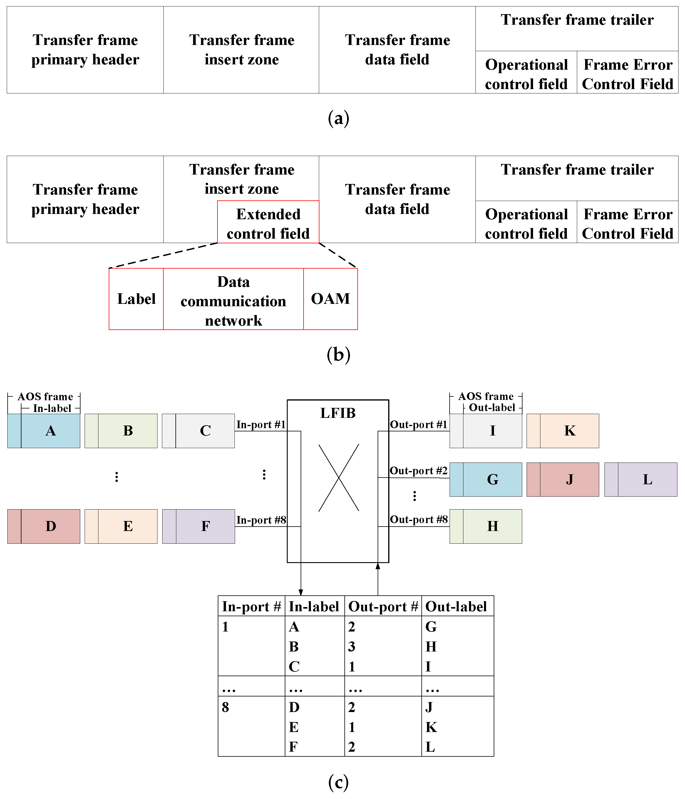
Applsci 12 06674 g001
Figure 2. The label-based CCSDS AOS frame switching. (a) The CCSDS recommended AOS frame. (b) The proposed AOS frame with extended control field. (c) The principle of label swapping for the AOS frame according to LFIB.
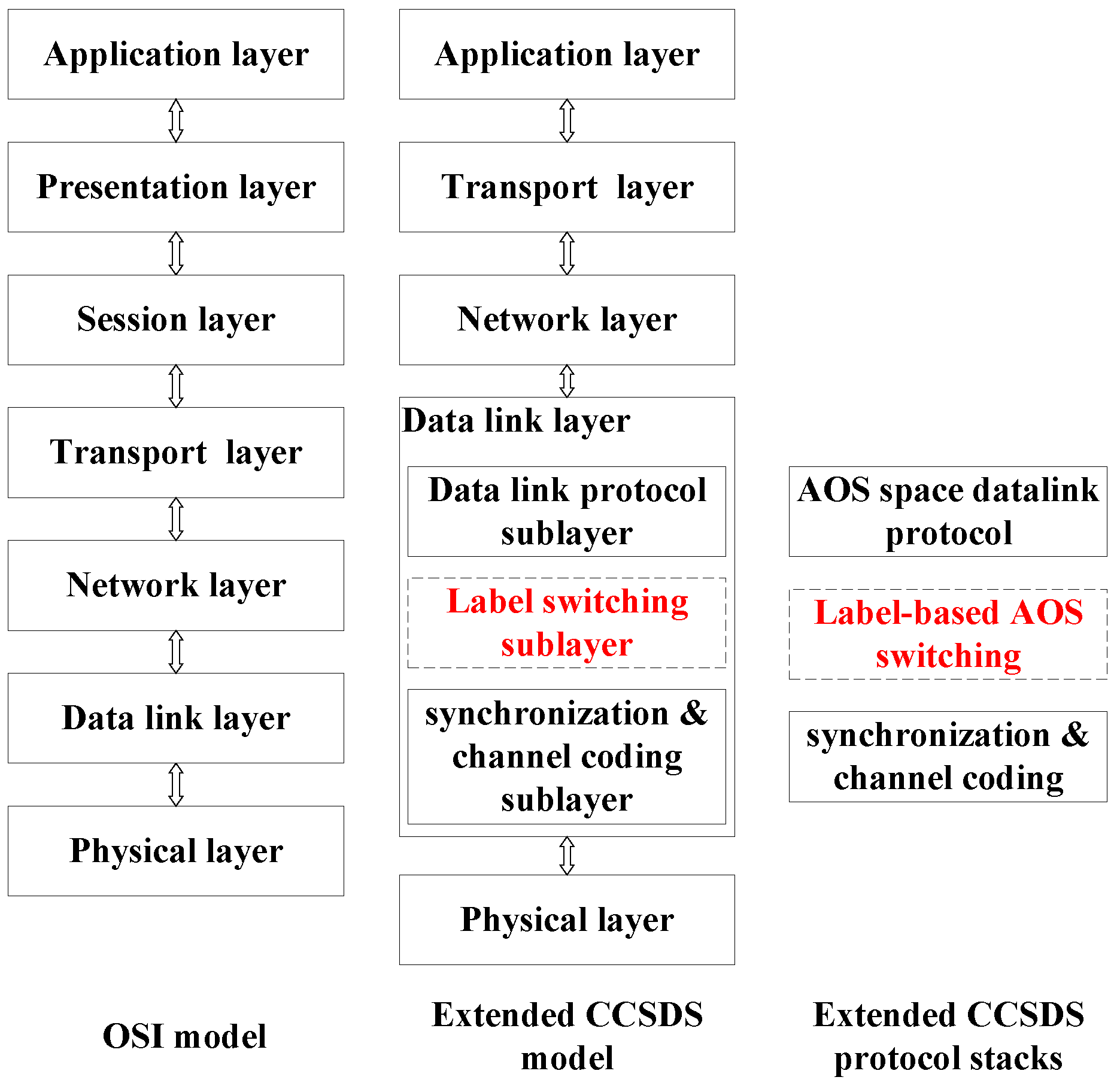
Applsci 12 06674 g002
Figure 3. OSI reference model v.s. label-based extended CCSDS reference model.
Applsci 12 06674 g003
Figure 4. The framework of SDN-based ISTNs simulation platform.
Applsci 12 06674 g004
Figure 5. The transmission of a fixed bit length managing and controlling message in the data communication network field of the AOS frame.
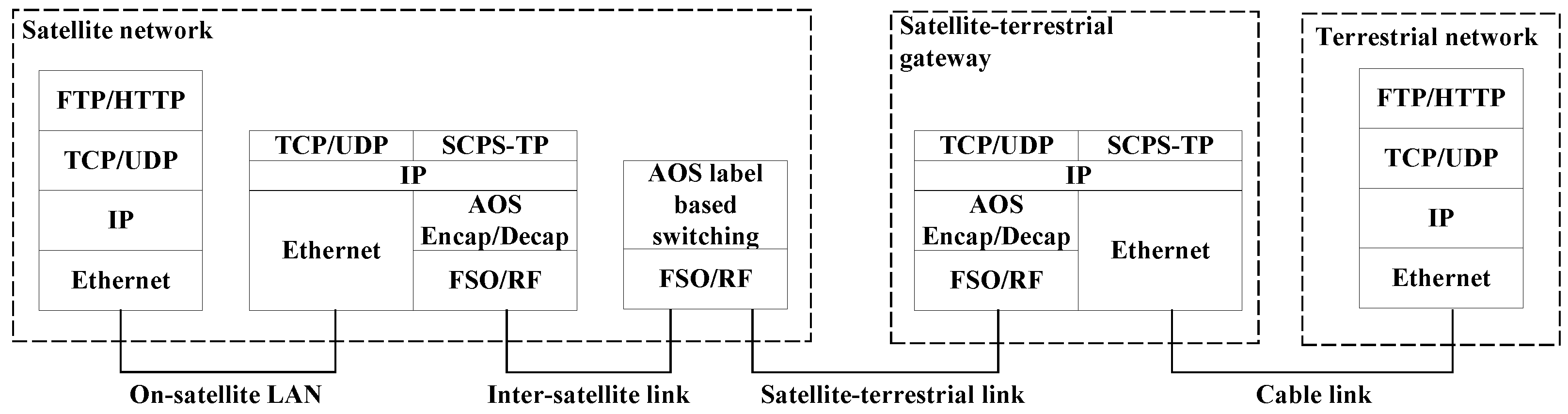
Applsci 12 06674 g005
Figure 6. The protocol framework of ISTNs.
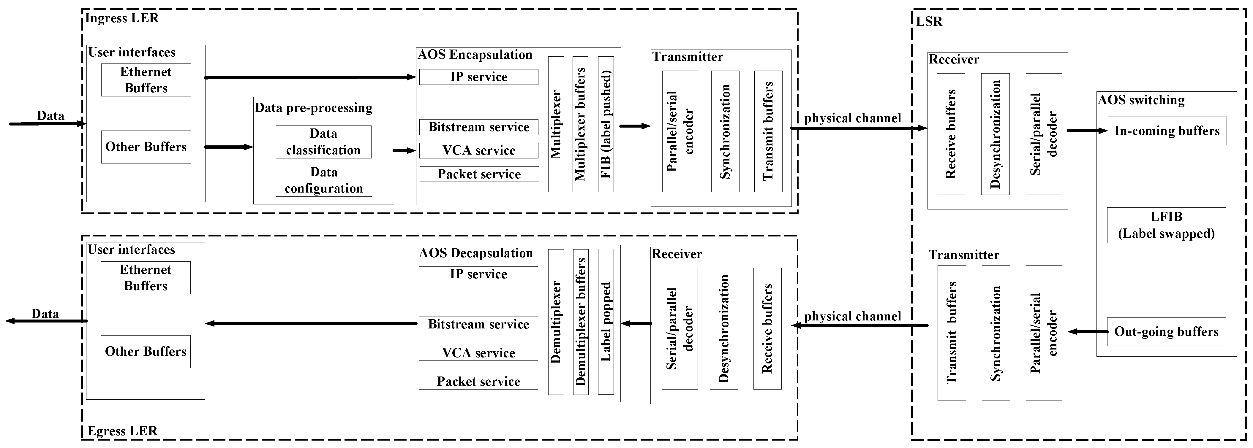
Applsci 12 06674 g006
Figure 7. The functional block diagram of four types of service over AOS frame.
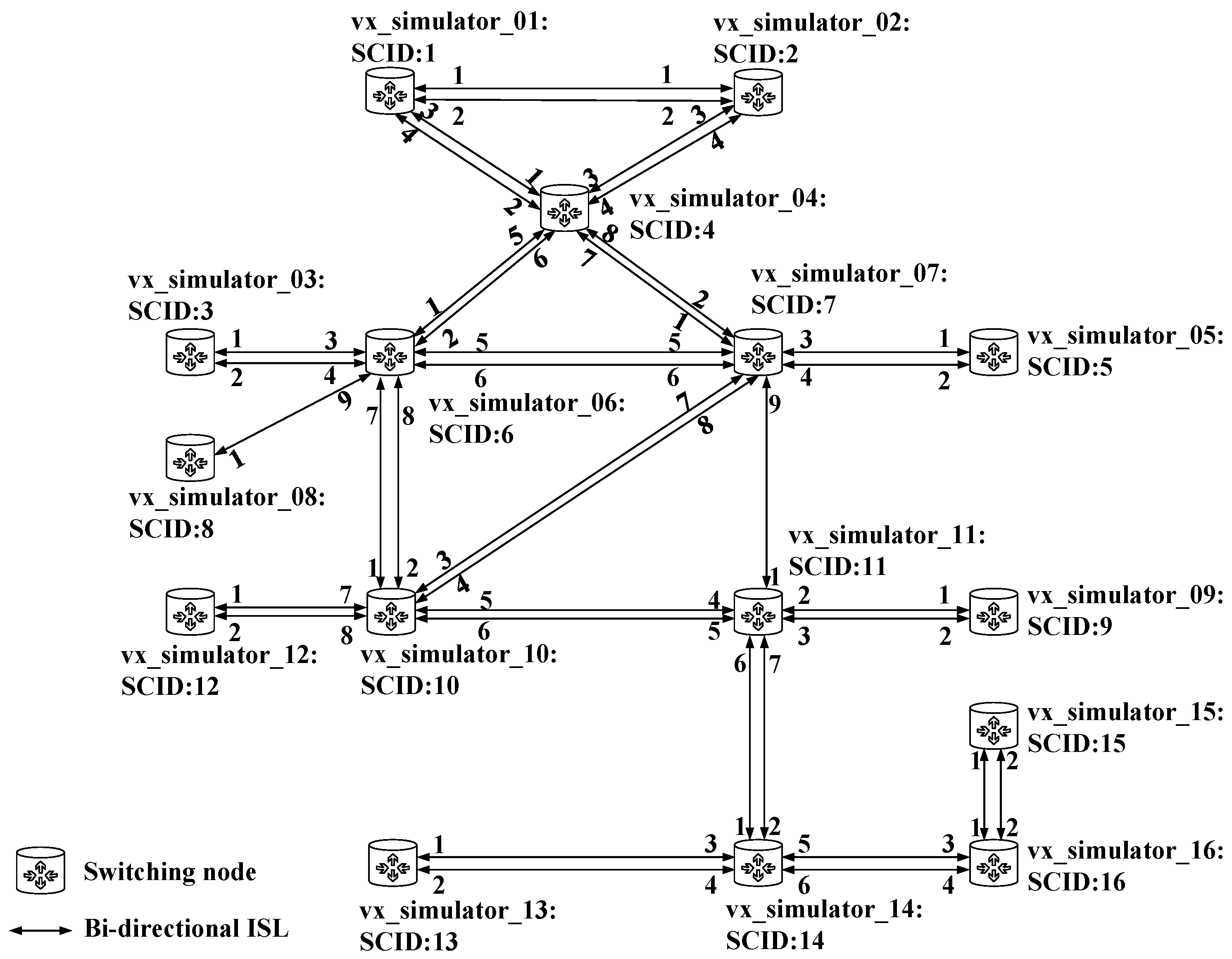
Applsci 12 06674 g007
Figure 8. The topology of VxWorks simulated network.
Applsci 12 06674 g008
Figure 9. Link-state database of optimized OSPF in node vx_simulator_01 (SCID 1).
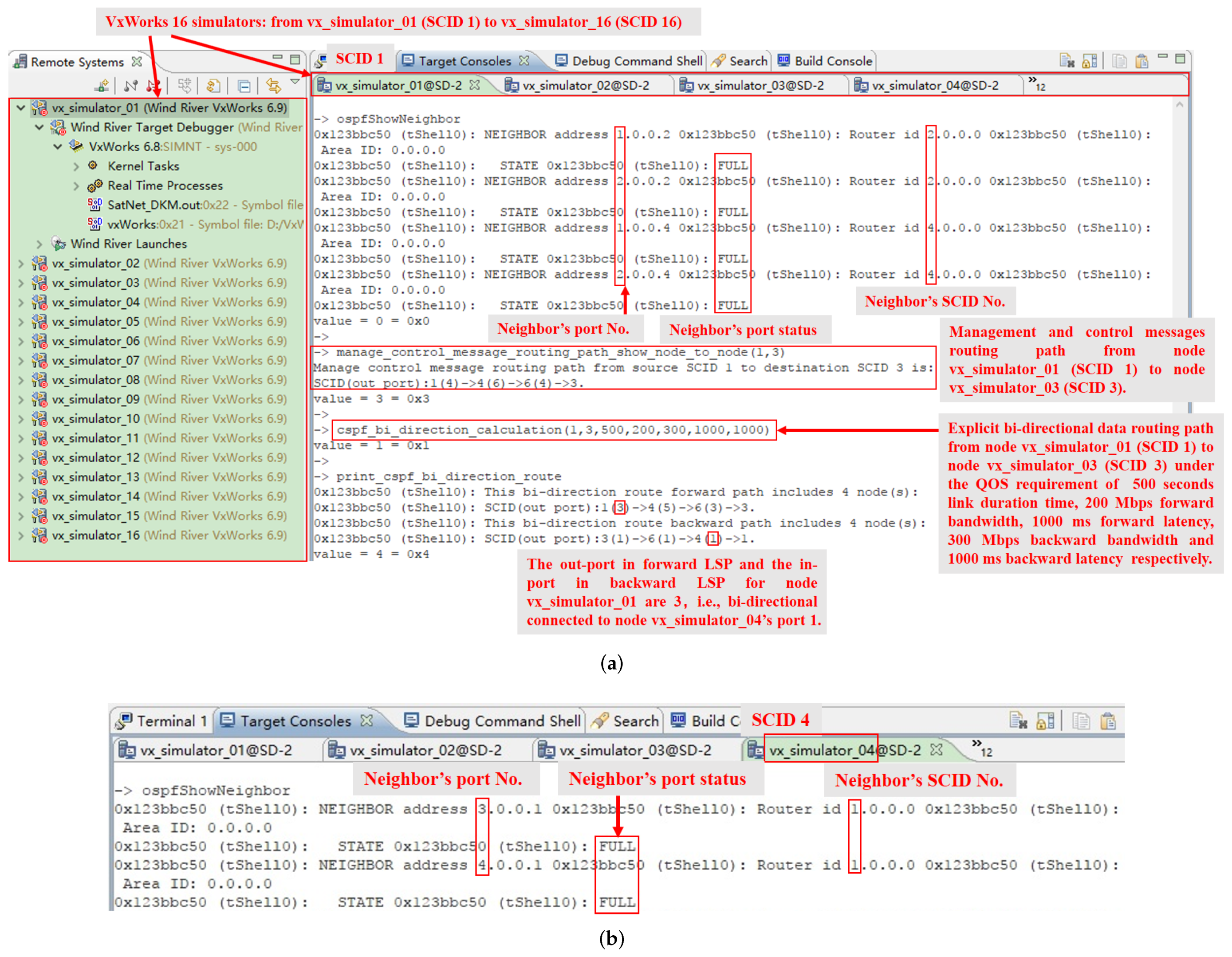
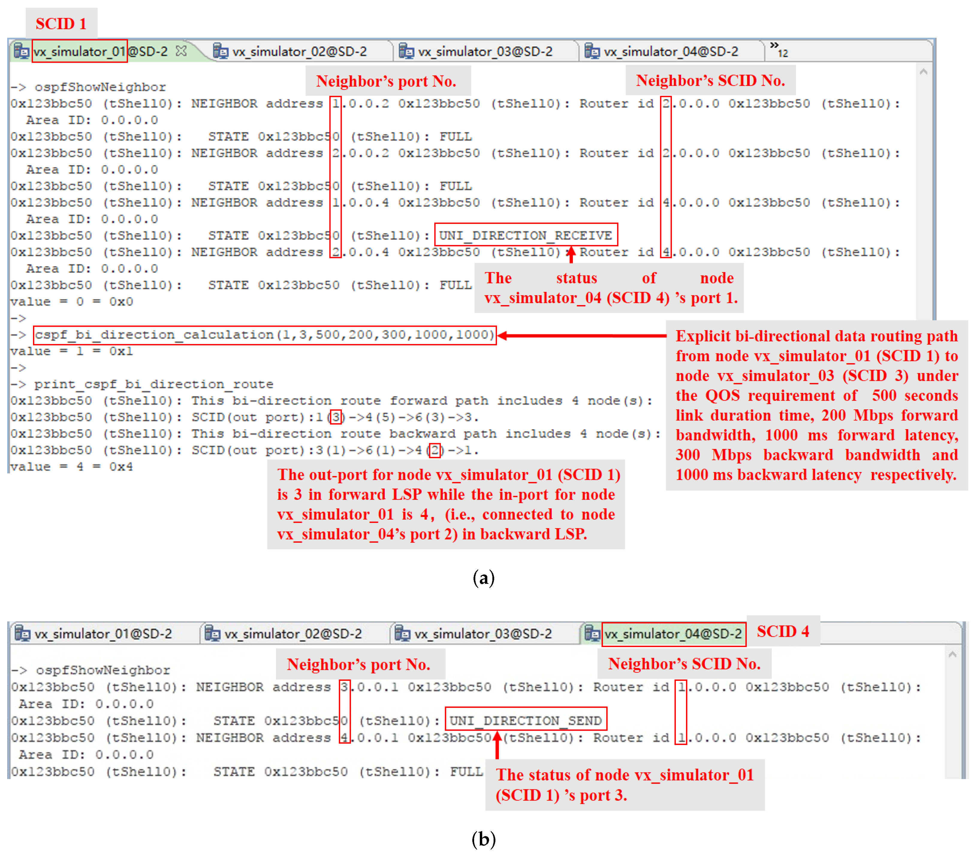
Applsci 12 06674 g009
Figure 10. Simulation in software platform with 16 simulated nodes under the circumstances of bi-directional link. (a) The status of a neighbor’s ports, routing path for managing and controlling messages, and explicit constraint routing path for data under QoS requirements in node vx_simulator_01 (SCID 1). (b) The status of a neighbor’s ports in node vx_simulator_04 (SCID 4).
Applsci 12 06674 g010
Figure 11. The principle of uni-directional OSPF protocol.
Applsci 12 06674 g011
Figure 12. Simulation in the software platform with 16 simulated nodes under the circumstances of uni-directional link. (a) The status of a neighbor’s ports and explicit constraint routing path for data under QoS requirements in node vx_simulator_01 (SCID 1). (b) The status of a neighbor’s ports in node vx_simulator_04 (SCID 4).
Applsci 12 06674 g012
Figure 13. Flooding restraint and flooding procedure for the two scenarios of satellites link variation.
Applsci 12 06674 g013
Figure 14. The semi-physical platform. (a) The semi-physical platform with VxWorks simulated nodes and FPGA boards. (b) The network topology of the semi-physical platform.
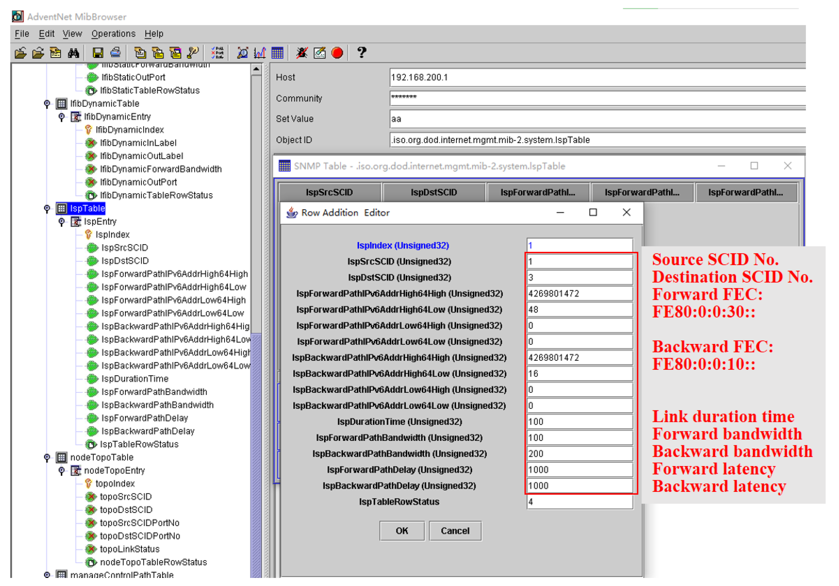
Applsci 12 06674 g014
Figure 15. The SNMP MIB of the semi-physical platform.
Applsci 12 06674 g015
Figure 16. The configuration from the network management system to the remote node uses the data communication network overhead in the AOS frame. (a) The configuration of static forwarding information base from the network management system (SNMP manager). (b) The managing and controlling message of static FIB transmitted by node vx_simulator_01 through southbound interface.
Applsci 12 06674 g016
Figure 17. A data communication network sequence diagram for a managing and controlling message, i.e., static FIB, from node vx_simulator_01 (SCID 1) to node vx_simulator_02 (SCID 2).
Applsci 12 06674 g017
Figure 18. A data communication network sequence diagram for a management and controlling flooding message, i.e., satellite link plan of connections, from node vx_simulator_01 (SCID 1) to other nodes.
Applsci 12 06674 g018
Figure 19. The link-state database of the optimized OSPF in node vx_simulator_01 (SCID 1). (a) The router link states of node vx_simulator_01 (SCID 1). (b) The router link states of node vx_simulator_02 (SCID 2). (c) The router link states of node vx_simulator_03 (SCID 3).
Applsci 12 06674 g019
Figure 20. The explicit constraint data routing computation under QoS requirements and the circumstances of a bi-directional link between node vx_simulator_01 (ingress LER, SCID 1), node vx_simulator_02 (LSR, SCID 2), and node vx_simulator_03 (egress LER, SCID 3). (a) The status of a neighbor’s port and explicit bi-directional data routing path computation in node vx_simulator_01 (SCID 1). (b) The explicit uni-directional data routing path computation between node vx_simulator_01 (SCID 1) and node vx_simulator_03 (SCID 3). (c) The status of a neighbor’s port in node vx_simulator_02 (SCID 2).
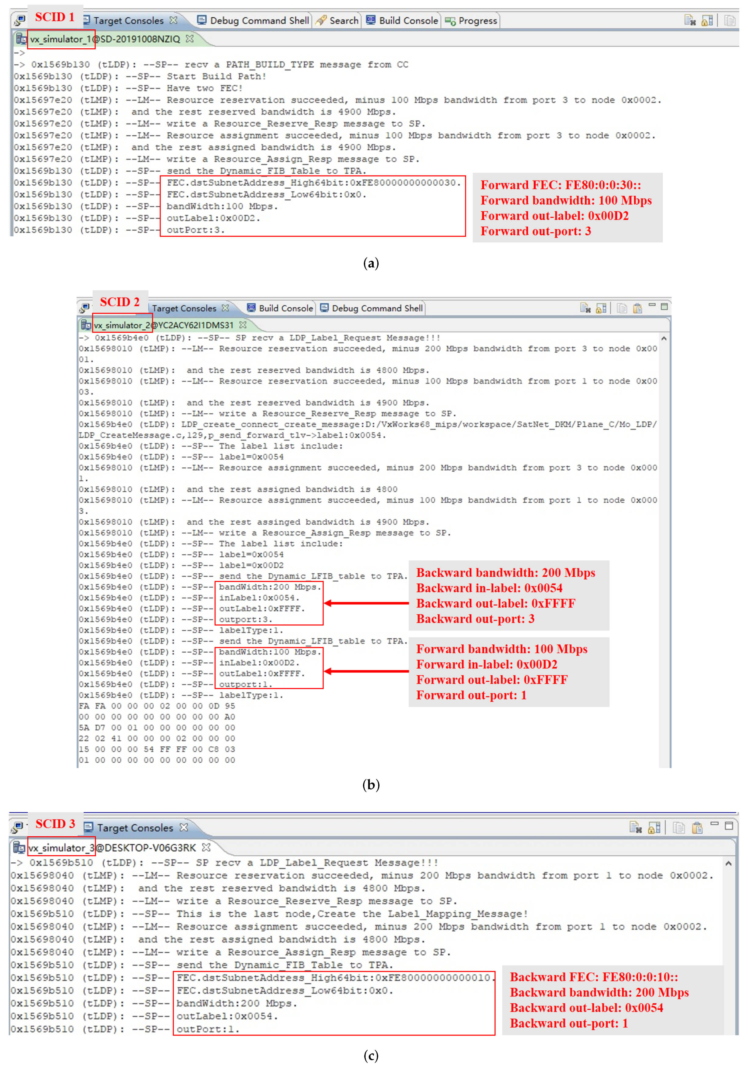
Applsci 12 06674 g020
Figure 21. The label distribution process of label switching path setup under QoS requirements and the circumstances of a bi-directional link between node vx_simulator_01 (ingress LER, SCID 1), node vx_simulator_02 (LSR, SCID 2), and node vx_simulator_03 (egress LER, SCID 3) in the semi-physical platform. (a) The label distribution process in node vx_simulator_01 (SCID 1). (b) The label distribution process in node vx_simulator_02 (SCID 2). (c) The label distribution process in node vx_simulator_03 (SCID 3).
Applsci 12 06674 g021
Figure 22. The label-based AOS frame switching in forward label switching path under the circumstances of bi-directional link between node vx_simulator_01 (ingress LER, SCID 1), node vx_simulator_02 (LSR, SCID 2) and node vx_simulator_03 (egress LER, SCID 3) in the semi-physical platform. (a) The IPv6 data transmitted from node vx_simulator_01 (SCID 1) to node vx_simulator_03 (SCID 3). (b) The forward-FIB-based label pushing of AOS frame in node vx_simulator_01 (SCID 1). (c) The forward-LFIB-based label swapping of AOS frame in node vx_simulator_02 (SCID 2). (d) The forward-FIB-based label popping of AOS frame in node vx_simulator_03 (SCID 3).
Applsci 12 06674 g022
Figure 23. The label-based AOS frame switching in backward label switching path under the circumstances of bi-directional link between node vx_simulator_01 (ingress LER, SCID 1), node vx_simulator_02 (LSR, SCID 2), and node vx_simulator_03 (egress LER, SCID 3) in the semi-physical platform. (a) The IPv6 data transmitted from node vx_simulator_03 (SCID 3) to node vx_simulator_01 (SCID 1). (b) The backward-FIB-based label pushing of AOS frame in node vx_simulator_03 (SCID 3). (c) The backward-LFIB-based label swapping of AOS frame in node vx_simulator_02 (SCID 2). (d) The backward-FIB-based label popping of AOS frame in node vx_simulator_01 (SCID 1).
Applsci 12 06674 g023
Figure 24. The explicit constraint data routing computation under QoS requirements and the circumstances of uni-directional link between node vx_simulator_01 (ingress LER, SCID 1, uni-directional sending), node vx_simulator_02 (LSR, SCID 2, uni-directional receiving), and node vx_simulator_03 (egress LER, SCID 3). (a) The status of a neighbor’s port and data routing computation in node vx_simulator_01. (b)The explicit uni-directional data routing path computation between node vx_simulator_01 and node vx_simulator_03. (c) The status of a neighbor’s port in node vx_simulator_02.
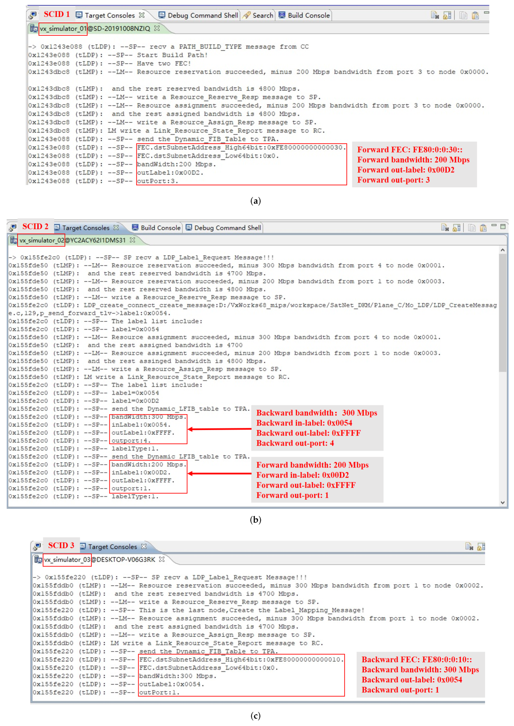
Applsci 12 06674 g024
Figure 25. The label distribution process of label switching path setup under QoS requirements and the circumstances of uni-directional link between node vx_simulator_01 (ingress LER, SCID 1), node vx_simulator_02 (LSR, SCID 2), and node vx_simulator_03 (egress LER, SCID 3). (a) The label distribution process in node vx_simulator_01 (SCID 1). (b) The label distribution process in node vx_simulator_02 (SCID 2). (c) The label distribution process in node vx_simulator_03 (SCID 3).
Applsci 12 06674 g025
Figure 26. The label-based AOS frame switching in forward label switching path under the circumstances of uni-directional link between node vx_simulator_01 (uni-directional sending) and node vx_simulator_02 (uni-directional receiving) in the semi-physical platform. (a) The IPv6 data transmitted from node vx_simulator_01 (ingress LER, SCID 1) to node vx_simulator_03 (egress LER, SCID 3). (b) The forward-FIB-based label pushing of AOS frame in node vx_simulator_01 (SCID 1). (c) The forward-LFIB-based label swapping of AOS frame in node vx_simulator_02 (SCID 2). (d) The forward-FIB-based label popping of AOS frame in node vx_simulator_03 (SCID 3).
Applsci 12 06674 g026
Figure 27. The label-based AOS frame switching in backward label switching path under the circumstances of uni-directional link between node vx_simulator_01 (uni-directional sending) and node vx_simulator_02 (uni-directional receiving) in the semi-physical platform. (a) The IPv6 data transmitted from node vx_simulator_03 (egress LER, SCID 3) to node vx_simulator_01 (ingress LER, SCID 1). (b) The backward-FIB-based label pushing of AOS frame in node vx_simulator_03 (SCID 3). (c) The backward-LFIB-based label swapping of AOS frame in node vx_simulator_02 (LSR, SCID 2). (d) The backward-FIB-based label popping of AOS frame in node vx_simulator_01 (SCID 1).
Applsci 12 06674 g027
Table 1. The routing path of managing and controlling messages between node vx_simulator_01 (SCID 1) and node vx_simulator_03 (SCID 3).
vx_simulator_01vx_simulator_04vx_simulator_06vx_simulator_03
Forward pathOut-port: 4In-port: 2, Out-port: 6In-port: 2, Out-port: 4In-port: 2,
Backward pathIn-port: 4Out-port: 2, In-port: 6Out-port: 2, In-port: 4Out-port: 2
Table 2. A bi-directional label switching path under the circumstances of bi-directional link between node vx_simulator_01 (SCID 1) and node vx_simulator_03 (SCID 3) in the software platform.
vx_simulator_01vx_simulator_04vx_simulator_06vx_simulator_03
Forward LSPOut-port: 3  1 In-port: 1, Out-port: 5In-port: 1, Out-port: 3In-port: 1
Backward LSPIn-port: 3  1 Out-port: 1, In-port: 5Out-port: 1, In-port: 3Out-port: 1
1 The out/in-ports of forward/backward label switching path for node vx_simulator_01 are the same, i.e., port 3.
Table 3. A Bi-directional label switching path between node vx_simulator_01 (SCID 1) and node vx_simulator_03 (SCID 3) under the circumstances of a uni-directional link in the software platform.
vx_simulator_01vx_simulator_04vx_simulator_06vx_simulator_03
Forward LSPOut-port: 3  1 In-port: 1, Out-port: 5In-port: 1, Out-port: 3In-port: 1
Backward LSPIn-port: 4  1 Out-port: 2, In-port: 5Out-port: 1, In-port: 3Out-port: 1
1 The out/in-ports of the forward/backward label switching path for node vx_simulator_01 are different, i.e., out-port 3 and in-port 4, respectively
Table 4. The routing path for managing and controlling messages from node vx_simulator_01 to node vx_simulator_02 and node vx_simulator_03, respectively, in the semi-physical platform.
vx_simulator_01vx_simulator_02vx_simulator_03
Routing pathOut-port: 4In-port: 4, Out-port: 1In-port: 1
Table 5. The bi-directional label switching path under QoS requirements and the circumstances of a bi-directional link between node vx_simulator_01, node vx_simulator_02, and node vx_simulator_03 in the semi-physical platform.
vx_simulator_01vx_simulator_02vx_simulator_03
Forward LSPOut-port: 3  1 In-port: 3, Out-port: 1In-port: 1
Out-label: 0x00D2In-label: 0x00D2, Out-label: 0xFFFFIn-label: 0xFFFF
Backward LSPIn-port: 3  1 Out-port: 3, In-port: 1Out-port: 1
In-label: 0xFFFFOut-label: 0xFFFF, In-label: 0x0054Out-label: 0x0054
1 The out/in-ports of forward/backward label switching path for node vx_simulator_01 are the same, i.e., port 3.
Table 6. The bi-directional label switching path under QoS requirements and the circumstances of uni-directional link between node vx_simulator_01 and node vx_simulator_03 in the semi-physical platform.
vx_simulator_01vx_simulator_02vx_simulator_03
Forward LSPOut-port: 3 1In-port: 3,Out-port: 1In-port: 1
Out-label: 0x00D2In-label: 0x00D2, Out-label: 0xFFFFIn-label: 0xFFFF
Backward LSPIn-port: 4 1Out-port: 4, In-port: 1Out-port: 1
In-label: 0xFFFFOut-label: 0xFFFF, In-label: 0x0054Out-label: 0x0054
1 The out/in-ports of forward/backward label switching path for node vx_simulator_01 are different, i.e., out-port 3 and in-port 4, respectively.
Publisher’s Note: MDPI stays neutral with regard to jurisdictional claims in published maps and institutional affiliations.

