Abstract
New alloys are needed to adapt the material properties and to improve the weldability of arc-based additive manufacturing processes. The classic development of welding filler materials is time-consuming and cost-intensive. For this reason, an alternative alloy concept is investigated and qualified here. This is based on the thin-film coating of welding filler materials by means of PVD coating. An HSLA steel DIN EN ISO 14341-A G 50 7 M21 is used as the base material. This is alloyed with the elements Al, Cr, Nb, Ni and Ti by means of PVD thin-film coating. This procedure represents an alternative alloy concept. In the scope of the qualification, the influence of the process and material properties is investigated, and the alternative alloying concept is compared with the classical alloying concept of secondary metallurgy. The investigations have shown that the thin film coating on the surface of the welding filler metal affects the process properties in the form of a changed arc length. Furthermore, the mechanical properties and the effect on the microstructure morphology were investigated. These were compared in the same chemical composition with a Mn4Ni2CrMo produced by secondary metallurgy. The results are in agreement with regard to the mechanical properties and the effect on the microstructure morphology.
1. Introduction
The continuously growing interest in resource efficiency and the associated development of additive manufacturing processes continue to result in the need to develop adapted filler materials, especially for wire arc additive manufacturing (WAAM) [1]. The functional principle of additive manufacturing is a layer-by-layer construction of structures [2]. Additive manufacturing using metallic materials is divided into powder-based and wire-based additive manufacturing [3]. Adapted material development for powder-based materials with little effort is possible by mixing the powders accordingly [4,5,6,7]. Wire-based additive manufacturing by means of an arc, also known as wire arc additive manufacturing, requires a welding filler material in wire form [8,9,10]. A corresponding alloy development up to the wire-shaped welding filler material is very costly. However, the necessity of this alloy development lies in the newly gained design freedom of the components and the possibility of being able to locally adapt material properties in a targeted manner depending on the load, for which the corresponding alloys are required [11]. It should also be noted that when components are built up in layers, a low surface tension means that the dimensional stability cannot be maintained. This means that the required geometry and its tolerances cannot be guaranteed, which are relevant parameters [12,13,14]. However, to develop new filler metals for this case, it is necessary to prepare steel melts, to alloy them based on secondary metallurgy and to then draw a welding wire for the process [15]. This procedure is costly and time-consuming. For this reason, a new innovative alloy concept is investigated for the development of a new type of filler metal with regard to wire arc additive manufacturing. For this purpose, a thin film coating is applied to a welding filler wire.
HSLA (high-strength low-alloy) steel is used as a filler metal. These low-alloy filler metals can be alloyed very well by means of PVD thin-film coating due to the low proportion of alloying elements. Such materials are used for complex bionic structures or spare parts with an adapted chemical composition that has to be procured quickly.
For the development of an alternative alloying concept, it has already been proven by preliminary investigations that a change in the mechanical properties occurs through the application of thin-film coatings on solid wire surfaces. Furthermore, it was shown that an influence on the process properties is caused by the alloying elements present on the surface [16,17,18,19,20,21,22]. In addition, an influence on the process properties and explicitly on the characteristics of the welding arc was recognized. This is due to the ionisation potential of the thin film layer. A validation between the alternative alloy concept and a filler metal produced by secondary metallurgy is described here.
Within the scope of the investigations, it is to be determined how the influence on the process properties is pronounced and what the reasons are for this. Furthermore, it must be investigated whether the process influence has an effect on the resulting weld seam.
For qualification of an alternative alloy concept, the influence on the material properties must also be identical to the properties of the classical alloy concept of secondary metallurgy. For this purpose, the effects of the different alloying concepts on the microstructure morphology and the mechanical properties are investigated. If the results agree, the qualification of the alternative alloy concept is successful.
2. Experimental
For the investigations of the influence on the arc behaviour and the mechanical properties, the base wire is coated with a thin film layer by a PVD process. The base wire is selectively alloyed with the elements Al, Cr, Nb, Ni and Ti and thus modified. The base wire is a DIN EN ISO 14341-A G 50 7 M21 4Mo, a high-strength low-alloy (HSLA) steel with a chemical composition according to the manufacturer’s specifications in Table 1.

Table 1.
Chemical composition DIN EN ISO 14341-A G 50 7 M21 4Mo [23].
The welding tests are executed in spray arc, as the effects on the arc are best evaluated visually in this range. The process adjustment variables are listed in Table 2.
Table 2.
Process adjustment variables.
For the investigations of the coated filler metals, two test set-ups, which differentiate between the influence on the material and the process properties, are distinguished. With regard to the influence on the process properties, the effects on the welding process and explicitly the effects on the arc, and which changes occur in the resulting weld seam are investigated. For the investigation, a welding torch is clamped in a static holder. A substrate sheet is clamped to a fixture on a robot arm. The robot arm performs the welding movement by moving the sheet under the static welding torch. Using this experimental set-up, which is shown schematically in Figure 1 on the left, individual welding beads are welded on a sheet and examined in the following. The test set-up for investigating the mechanical properties is shown on the right in Figure 1. For this purpose, a welded composite is created, and the specimens for the material testing are taken from this composite.
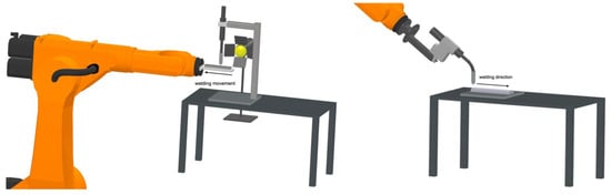
Figure 1.
Test set-ups process and material property.
A welding arc is very bright, so to be able to record it using a high-speed camera, it is recorded using the backlight method. For this, appropriate filters are used in front of the camera lens and a lamp with a high lumen value. This lamp shines directly into the camera. The welding process is carried out in the axis of the lamp and camera lens. Due to the static clamping of the welding torch and the execution of the welding movement by the robot, the welding process can be recorded optically.
Physical Vapour Deposition
The thin film coating applied to the surface of the filler wires is applied using magnetron sputtering, a physical vapour deposition (PVD) technology, which is a coating process [24,25,26]. Such a coating process is carried out in a coating chamber of a PVD system, which is shown in Figure 2. The process chamber in the case is a vacuum chamber, which is equipped with two external heaters on the sides of the process chamber and a central heater in the middle of the charging table. The charging table in the middle of the process chamber rotates during the process. The elements to be coated are placed in the form of targets on the six cathodes in the system. These targets are plates of pure elements that are dissolved from the surface during the process by physical vapour deposition and coat the substrate. The system used for the investigations is a CC800/9 Custom from the company CemeCon.
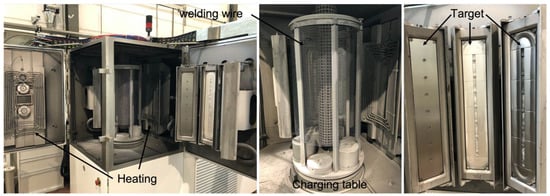
Figure 2.
PVD system.
A process sequence for coating substrate first requires opening the vacuum chamber into which the substrate is placed on the charging table. To start the process, a component test is first run through. In this scope, a pre-vacuum is built up by a rotary vane pump, and a high vacuum is generated in the process chamber by means of two turbomolecular pumps. During the generation of the high vacuum, an argon atmosphere is simultaneously built up in the process chamber. The process chamber is heated to reach the process temperatures. The process includes a pre-treatment of the surface, which is declared as etching, which effectively represents a reverse coating. This pre-treatment improves the adhesion of the coating and removes impurities from the substrate. The actual coating process can then be started. During this process, the desired elements are applied to the surface of the substrate. During the process, it is also possible to create nitrides or oxides, which are produced by the targeted introduction of different gases by changing the atmosphere in the process chamber. After the coating process, the process chamber is cooled down and remains under vacuum. Once the aeration temperature has been reached, the vacuum pumps can be switched off, the system can be ventilated, and the substrate can be removed. Figure 3 shows the process flow in simplified form.
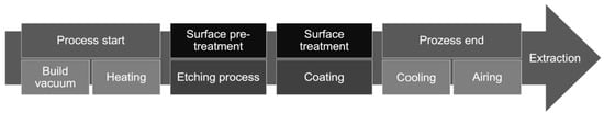
Figure 3.
PVD coating process [27,28].
The substrate, or in this case, the filler metal, is wound on the charging table, which is located in the coating chamber (Figure 2). To achieve a uniform coating of the welding wire, the charging table is continuously rotated during the coating process. By heating the process chamber, the coating adhesion is improved. A thin film coating on a welding wire is schematically shown in Figure 4 on the left. A matching wire grind is shown on the right side in Figure 4. To create the wire grind, the welding wire is embedded, ground and polished, and photographed under an optical microscope.
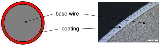
Figure 4.
PVD coating on wire surface [16].
3. Results
3.1. Influence on the Arc
Figure 5 shows the individual arc recordings of the modified filler metals. The mean arc lengths over the process are shown as an example. The mean arc lengths were averaged over 50,000 frames per second. The modified filler metals with the elements Al, Cr, Nb, Ni and titanium to be investigated are shown. In addition, the base wire is examined. Usually, this is supplied with a copper layer, which represents the base wire + Cu. However, for the investigation of the modifications, a bare white wire without a copper layer is used. For this reason, these two types of base wire are also examined.
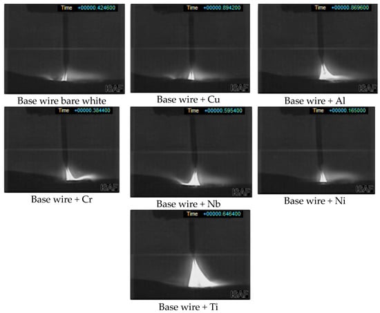
Figure 5.
Arc recordings.
The first theory explaining the change in arc length is that it actually remains constant and only the exposed part of the arc appears longer or shorter. This means that with a shorter arc, a large part of the arc is covered, and the arc base is moved deeper into the component. This would result in an increase in the burn-in. To test this thesis, the individual beads are separated, and the seam geometry is closely examined. The comparison of the different seam geometries shows that the seam volume, the width and the penetration change. If the penetration is set in relation to the arc length, a correlation between exposed arc length and penetration can be recognised. However, this is not a question of a constant arc length that shifts. It can only be said that the depth of the penetration decreases with increasing arc length. Furthermore, current and voltage were recorded during the welding tests to be able to recognise an influence on the applied power and a possible change in the values due to the coatings. For the evaluation, interpolation times of 1 s and 10 s were selected for each recording. The welding current source is a source with constant voltage characteristics. This means that the present source regulates the current and tries to keep the voltage relatively constant.
According to Li [29], the arc length is also dependent on the current. The shorter the arc, the higher the current and the lower the voltage. The same applies analogously for a longer arc. This relationship becomes apparent when an extension of the arc is considered, and it results in a greater distance being passed. The voltage increases accordingly. If the distance is shorter, a lower voltage is necessary, and a higher current can be transported. However, the recorded values show that the current increases with aluminium and especially with titanium. However, the greatest arc lengths can be seen with these two coatings. These values are in clear contrast to the theory that with a longer arc length, the voltage increases and the current decreases. In addition, increasing the current usually causes a larger burn-in. This is not the case here because the penetration decreases for both aluminium and titanium. However, this theory refers to a constant burning arc, where all parameters remain the same except for the distance of the torch to the workpiece, which changes the arc length and counter-regulates the current source. Under these constant conditions, the behaviour of current and voltage in relation to the arc is exactly as described. In this work, however, the nature of the welding wire is changed, which has further effects on the arc and its properties.
Due to the thin film coating of additional elements on the wire surface, there must be effects on the arc that change its length. Another theory is the energy required to bring an element into the gas phase. For this purpose, the sublimation energy is used and related to the layer thickness and its element-dependent molar mass. The necessary sublimation energy to be applied, here related to 1 mm3 wire, shows that different energies can result. However, no analogy can be drawn between the necessary energies and the resulting arc length. Furthermore, an influence of the electrical conductivity of the coated elements was considered. The conductivity of the outer layer is of relevance in the contact point of the current contact tube, since with constant power in the system and a variable electrical conductivity, the voltage dropping in the contact resistance varies and, accordingly, the voltage in the arc is changed relatively. The measurement of the resistance is measured by means of a test rig that determines the resistance at electrode caps for spot welding. For this purpose, the wire is positioned between the two electrode caps and pressed together with a test force of 100 N. The resistance of the wire is then measured. The resistance of the wire is then determined in the current contact tube. There are no contact forces in a current contact tube, but the test force is set at 100 N to reduce the measurement inaccuracy when determining the resistance. In the theory of variable electrical conductivity in the current contact tube, an aluminium oxide layer must be assumed on the weld filler coated with aluminium, which considerably reduces the conductivity of aluminium. However, this behaviour could not be proven after measurements of the conductivity of the individual layers. However, a force of 100 N was applied to the wire to obtain a higher accuracy for the measurement. Under certain circumstances, this force may have been sufficient to break up the oxide layer. However, it is noticeable in the set-up of a welding device that the wire in the wire conveyor unit is subject to similar forces, which break up a possible oxide layer, analogous to the test set-up.
From the investigations, an influence on the ionisation in the arc results. According to Schellhase [30], the element with the lowest ionisation energy decisively takes over the ionisation state in an arc. Even traces of metal vapour have a major influence. The ionisation state refers to the electrical conductivity and the temperature in the arc.
The ionisation energies of aluminium and titanium have a lower necessary energy than iron in the different ionisation states.
Figure 6 shows the arc temperature plotted against the ionisation potential. The line in the diagram includes the theoretically calculated values and the crosses represent the experimentally determined values for a MIG process. It can be seen that aluminium and titanium each have a lower ionisation potential than iron. A lower ionisation potential means a higher ionisation of the gas, which in turn causes an increase in ions and electrons in the arc. A higher number of electrons means that more current can be transported.
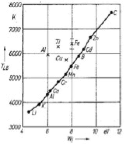
Figure 6.
Average arc temperature over the ionisation potential of the elements [30].
As a result, the conductivity of the arc increases and the voltage does not increase with a longer arc length. Furthermore, due to the lower ionisation potential, less energy is needed to obtain more electrons in the arc. This energy is then, in turn, available to the arc to keep the extension stable. In this study, aluminium is the element with the lowest ionisation potential but does not have the longest arc length. The diagram in Figure 6 shows that aluminium lowers the temperature in the arc. A reduction in the arc temperature results in a reduction in the electrons available in the arc, as thermal ionisation accounts for a large proportion of the ionisation in the arc. Furthermore, aluminium has a lower ionisation potential only in the first ionisation stage. The further ionisation stages require a higher energy input than is the case with titanium. It can be deduced that aluminium has a longer arc length compared to the base wire, as the ionisation energy of aluminium is lower. Furthermore, it can be deduced that titanium, however, has the longest arc length because titanium, in contrast to aluminium, does not reduce the arc temperature.
The investigations have shown that the arc length varies depending on the ionisation energy and the change in temperature of the arc plasma. The lower the ionisation energy, the higher the electrical conductivity in the arc, which increases the arc length. When the arc temperature is reduced, the thermal ionisation is lowered, which causes a reduction in the electrical conductivity. This reduces the arc length. When using the alternative alloy concept, it should be noted that the process properties are influenced in the form of the change in arc length. However, there is only a marginal effect on the weld [31,32].
3.2. Comparison of Alloying Concepts
As a comparison of the alloy concepts, the base wire DIN EN ISO 14341-A G 50 7 M21 4Mo examined here is modified in its chemical composition so that it corresponds to a Mn4Ni2CrMo. The Mn4Ni2CrMo was produced by secondary metallurgy. These two filler metals are compared in their microstructural morphologies and mechanical properties. A welded composite is created for this purpose, shown in Figure 7.
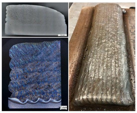
Figure 7.
Welded composite.
As a basis, the chemical compositions are first considered, which, according to the manufacturer’s specifications, should be present in the Mn4Ni2CrMo, be what the standard prescribes and be what is actually present in the alloy according to optical emission spectroscopy (OES). For comparison, the chemical composition of the alternative alloy concept is determined and listed in Table 3.
Table 3.
Chemical composition.
In the reference structure in Figure 7, on the left, a clearly ferritic/martensitic structure can be recognised. The ferrite is partly polygonal and an acicular ferrite. For comparison, the rebuilt modified 4Mo is shown on the right in Figure 8. The same ocular magnification is selected. The difference in the exposure ratios is not to be considered in the observation, as this has no relevance. The microstructure of the modified 4Mo has the same ferritic/martensitic microstructure as the microstructure of the reference. Here also, ferrite is present both as grain boundary ferrite and as acicular ferrite. From a purely microstructural point of view, no difference can be detected between the reference and the alternatively alloyed filler metal.
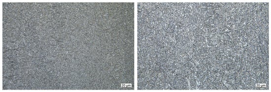
Figure 8.
Microstructure morphology Mn4Ni2CrMo secondary metallurgy (left) alternative alloy (right) at 500× magnification.
Beyond the microstructure, the mechanical properties should also be comparable. As proven several times in preliminary work and in the course of the project, a direct conclusion can be drawn from the microstructural properties to the mechanical properties. The interpass temperature maintained in this work was kept constant at 150 °C for all welding tests. Furthermore, it must be taken into account that the chemical composition varies in relation to the standard, the manufacturer’s specifications and the composition determined via optical emission spectroscopy. In two different investigations, significant differences in the yield strength and tensile strength of the weld metal were also determined. In none of the tests was the yield strength according to the manufacturer’s specifications achieved, and in only one was the tensile strength achieved. When comparing the strength values with the alternatively alloyed Mn4Ni2CrMo, it can be seen that the yield strength is comparable to the rest of the tests. The tensile strength is slightly below the specified values. However, as already described, this can also be attributed to the difference in the interpass temperature and the variance in the chemical composition. Due to the high scatter of the results, the alternative alloy concept is considered to have normal variance and to be comparable. Compared to the base wire, a significant increase in strength properties can be seen in Figure 9. The replication of an already existing alloy by means of thin film coating can be considered as successfully proven in this framework of HSLA steels.
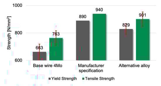
Figure 9.
Tensile strength different alloys.
The results from the investigations have shown that the alloying elements have the same effect on the microstructure as a thin film coating on the surface of welding consumables as they do via secondary metallurgy. When using the alternative alloying concept, it should be noted that a process influence occurs in the form of a change in the arc length. However, the weld seams are only marginally influenced. A qualification of the alternative alloy concept in comparison to a filler metal produced via secondary metallurgy could be made based on the microstructure morphology and the tensile strength. The agreement of the chemical composition shows minor differences here, which must be further investigated and adjusted in further studies.
4. Discussion
To qualify the alternative alloy concept, an existing filler metal produced by secondary metallurgy with the same chemical composition was produced with the reference wire by appropriate modification. When comparing the weld metal microstructures, no difference was found between the different alloying methods. The mechanical properties related to hardness and static strength showed marginal deviations. However, these can be explained by an inhomogeneous chemical composition and different welding parameters, and can therefore be neglected. It could be shown that alloying by means of PVD thin film coating on the surface of filler metals in the field of high-strength low-alloy steels is an alternative alloying concept. This can considerably reduce the effort of alloy development with regard to additive manufacturing with high-strength low-alloyed materials. During the production of specimens, only the influence of the welding process with regard to the change in the arc length has to be taken into consideration. However, this influence has no effect on the mechanical properties of the weld metal.
The results show that the alternative alloy concept can be used in the scope of high-strength low-alloy steels for the alloying elements that have been investigated. This is especially valid for the thin film coating and the correspondingly low-alloy contents. The qualification is successful for this application case, as the different alloy concepts match in their effects on the microstructure morphology and mechanical properties. A clamped tensile specimen is shown in Figure 10.
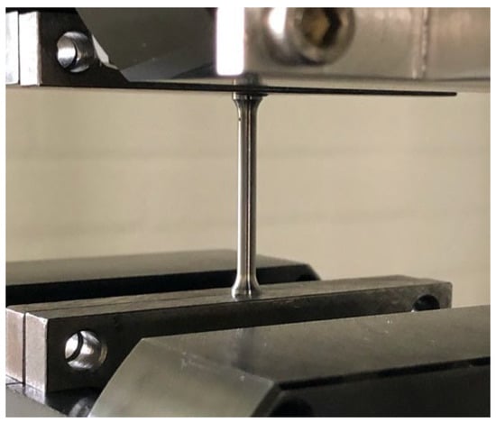
Figure 10.
Clamped tensile specimen.
For further investigations, thin film coatings are to be produced in a continuous pass-through PVD system. This will lead to a more homogeneous coating and a more targeted adjustment of the chemical properties. Furthermore, influencing the surface tension of steel melts with regard to additive manufacturing is of major interest. By means of the thin film coating, a targeted adjustment of the melt pool of steel melts can be made. Considering additive manufacturing, an improvement in the shape retention can be achieved by the modification. In addition, it is possible to adapt the chemical composition of the filler materials locally and specifically to the loads on the component and the mechanical properties required. In this way, higher flexibility in the production of complex components can be achieved.
5. Conclusions
The results of this work are as follows:
- -
- Qualification of an alternative alloy concept;
- -
- PVD thin film coating influences the arc length of the welding process;
- -
- Alloying elements on the surface of filler metals behave the same way as filler metals produced by secondary metallurgy;
- -
- The mechanical properties and effects on the microstructure morphology do not differ in the different alloying concepts;
- -
- Reduction in the effort to create new alloys for the additive manufacturing of HSLA steels.
The results of this work qualify the alternative alloying concept for HSLA steels, and further investigations can be carried out within this framework. This will be the basis for another tool for extending wire arc additive manufacturing.
Author Contributions
Conceptualization, M.L. and K.T.; methodology, M.L.; software, M.L.; validation, M.L.; formal analysis, M.L.; investigation, M.L. and K.T.; resources, M.L.; data curation, V.W.; writing—original draft preparation, M.L.; writing—review and editing, M.L.; visualization, M.L.; supervision, V.W.; project administration, V.W.; funding acquisition, V.W. All authors have read and agreed to the published version of the manuscript.
Funding
The results of this publication were developed within the framework of a completed DFG project with project number 393234340, and the results were completely compiled in a dissertation.
Data Availability Statement
The data that the presented studies are based on are available from the authors upon reasonable request.
Conflicts of Interest
The authors declare no conflict of interest.
References
- Günther, J.; Niendorf, T. Neue Werkstoffe über Additive Fertigung; TU Bergakademie Freiberg: Freiberg, Germany, 2015. [Google Scholar]
- Solomon, I.J.; Sevvel, P.; Gunasekaran, J.; Tanushkumaar, P. A review on additive manufacturing of alloys using laser metal deposition. Mater. Today Proc. 2022. [Google Scholar] [CrossRef]
- Gunasekaran, J.; Sevvel, P.; Solomon, I.J.; Tanushkumaar, P. A brief review on the manufacturing of metal components using selective laser melting. Mater. Today Proc. 2022. [Google Scholar] [CrossRef]
- Ma, Y.; Cuiuri, D.; Hoye, N.; Li, H.; Pan, Z. The effect of location on the microstructure and mechanical properties of titanium aluminides produced by additive layer manufacturing using in-situ alloying and gas tungsten arc welding. Mater. Sci. Eng. A 2015, 631, 230–240. [Google Scholar] [CrossRef]
- Gu, D.; Wang, Z.; Shen, Y.; Li, Q.; Li, Y. In-Situ TiC particle reinforced Ti–Al matrix composites: Powder preparation by mechanical alloying and Selective Laser Melting behavior. Appl. Surf. Sci. 2009, 255, 9230–9240. [Google Scholar] [CrossRef]
- Spears, T.G.; Gold, S.A. In-process sensing in selective laser melting (SLM) additive manufacturing. Integr. Mater. Manuf. Innov. 2016, 5, 16–40. [Google Scholar] [CrossRef] [Green Version]
- Fischer, M.; Joguet, D.; Robin, G.; Peltier, L.; Laheurte, P. In Situ elaboration of a binary Ti–26Nb alloy by selective laser melting of elemental titanium and niobium mixed powders. Mater. Sci. Eng. C 2016, 62, 852–859. [Google Scholar] [CrossRef] [PubMed] [Green Version]
- Lange, J. 3D-Druck im Stahlbau—Additive Fertigung von Details, Verbindungen und Bauteilen. Stahlbau 2020, 89, 981–991. [Google Scholar] [CrossRef]
- Feldmann, M.; Kühne, R.; Citarelli, S.; Reisgen, U.; Sharma, R.; Oster, L. 3D-Drucken im Stahlbau mit dem automatisierten Wire Arc Additive Manufacturing. Stahlbau 2019, 88, 203–213. [Google Scholar] [CrossRef]
- Srinivasan, D.; Sevvel, P.; Solomon, I.J.; Tanushkumaar, P. A review on Cold Metal Transfer (CMT) technology of welding. Mater. Today Proc. 2022. [Google Scholar] [CrossRef]
- Leicher, M.; Kamper, S.; Treutler, K.; Wesling, V. Multi-material design in additive manufacturing—Feasibility validation. Weld World 2020, 64, 1341–1347. [Google Scholar] [CrossRef]
- Williams, S.; Comas, T.F.; Diao, C.; Ding, J.; Zhao, Y. A Passive Imaging System for Geometry Meas-urement for the Plasma Arc Welding Process. IEEE Trans. Ind. Electron. 2017, 64, 7201–7209. [Google Scholar] [CrossRef] [Green Version]
- Ding, D.; Pan, Z.; Cuiuri, D.; Li, H. A multi-bead overlapping model for robotic wire and arc additive manufacturing (WAAM). Robot. Comput. Integr. Manuf. 2015, 31, 101–110. [Google Scholar] [CrossRef] [Green Version]
- Abe, T.; Sasahara, H. Layer geometry control for the fabrication of lattice structures by wire and arc additive manufacturing. Addit. Manuf. 2019, 28, 639–648. [Google Scholar] [CrossRef]
- Schwarz, B. Kupfer runter, Produktivität rauf. Die neue Generation unverkupferter MAG-Drahtelektroden. gehalten auf der GST. 2006. [Google Scholar]
- Leicher, M.; Treutler, K.; Wesling, V. Prüfung mechanischer Eigenschaften von additiv gefertigten Proben mittels beschichteten Schweißdrahtelektroden. Tag. Werkst. 2020, 5, 2020. [Google Scholar]
- Gehling, T.; Treutler, K.; Wesling, V. Development of surface coatings for high-strength low alloy steel filler wires and their effect on the weld metal microstructure and properties. Weld World 2021, 65, 1591–1597. [Google Scholar] [CrossRef]
- Gehling, T.; Treutler, K.; Wesling, V. Targeted influence on the weld strength of high-strength fine-grain structural steels in the GMA welding process through functionalized weld material surfaces. Weld World 2019, 63, 783–792. [Google Scholar] [CrossRef]
- Wesling, V.; Treutler, K.; Gehling, T. Influence on the weld strength of high-strength fine-grained structural steels by thin-film-coated GMA welding electrodes. IOP Conf. Ser. Mater. Sci. Eng. 2018, 373, 012006. [Google Scholar] [CrossRef] [Green Version]
- Treutler, K. Schweißen von Leichtbaurahmenkonstruktionen—Funktionale Werkstoffauswahl und Schweiß-Zusatzwerkstoffmodifikation. Ph.D. Thesis, TU Clausthal, Clausthal-Zellerfeld, Germany, 2019. [Google Scholar]
- Treutler, K.; Hamje, J.; Schram, A.; Wesling, V. Nutzung von Al-beschichteten Drahtelektroden beim MSG-Schweißen zur Minderung des Legierungsabbrandes. Clausthal-Zellerfeld, Fortschrittsberichte der Materialforschung und Werkstofftechnik, 2. Symposium Materialtechnik. 2017. [Google Scholar]
- Treutler, K.; Wesling, V. Usage of Ti-surface-modified filler material to increase the joint strength of High-Strength Low Alloyed (HSLA) steels under different load types. Appl. Sci. 2020, 2, 2137. [Google Scholar] [CrossRef]
- Hermann Fliess & Co. GmbH. MSG-Drahtelektroden für Hochfeste Feinkornbaustähle ED-A31; Hermann Fliess & Co. GmbH: Duisburg, Germany, 2021. [Google Scholar]
- Wasa, K.; Kitabatake, M.; Adachi, H. Thin Film Materials Technology: Sputtering of Compound Materials; William Andrew Pub.: Norwich, NY, USA ; Springer: Berlin/Heidelberg, Germany, 2004. [Google Scholar]
- Kelly, P.J.; Arnell, R.D. Magnetron sputtering: A review of recent developments and applications. Vacuum 2000, 56, 159–172. [Google Scholar] [CrossRef]
- Mattox, D.M. Handbook of Physical Vapor Deposition (PVD) Processing. In Handbook of Physical Vapor Deposition (PVD) Processing; Elsevier: Amsterdam, The Netherlands, 2010; pp. i–iii. [Google Scholar] [CrossRef]
- Baptista, A.; Silva, F.J.G.; Porteiro, J.; Míguez, J.L.; Pinto, G.; Fernandes, L. On the Physical Vapour Deposition (PVD): Evolution of Magnetron Sputtering Processes for Industrial Applications. Procedia Manuf. 2018, 17, 746–757. [Google Scholar] [CrossRef]
- Gassner, M. Energy consumption and material fluxes in hard coating deposition processes. Surf. Coat. Technol. 2016, 299, 49–55. [Google Scholar] [CrossRef]
- Li, P.; Zhang, Y.-M. Robust sensing of arc length. IEEE Trans. Instrum. Meas. 2001, 50, 697–704. [Google Scholar] [CrossRef]
- Schellhase, M. Der Schweißlichtbogen-ein technologisches Werkzeug, 1. Auflage; Deutscher Verlag für Schweisstechnik: Düsseldorf, Germany, 1985. [Google Scholar]
- Leicher, M.; Treutler, K.; Wesling, V. Einfluss auf die Lichtbogeneigenschaften von PVD beschichteten MSG Drahtelektroden. 42. Assistentenseminar. 2022. [Google Scholar]
- Leicher, M. Entwicklung Eines Alternativen Konzeptes zur Legierungsentwicklung von Schweißzusatzwerk-Stoffen mittels PVD Dünnfilmbeschichtung. Ph.D. Thesis, TU Clausthal, Clausthal-Zellerfeld, Germany, 2022. [Google Scholar]
- Hermann Fliess & Co. GmbH. MSG-Drahtelektroden für hochfeste Feinkornbaustähle ED-FK1000; Hermann Fliess & Co. GmbH: Duisburg, Germany, 2021. [Google Scholar]
Publisher’s Note: MDPI stays neutral with regard to jurisdictional claims in published maps and institutional affiliations. |
© 2022 by the authors. Licensee MDPI, Basel, Switzerland. This article is an open access article distributed under the terms and conditions of the Creative Commons Attribution (CC BY) license (https://creativecommons.org/licenses/by/4.0/).