Article

An Accurate UAV Ground Landing Station System Based on BLE-RSSI and Maximum Likelihood Target Position Estimation

by
Jaime Avilés-Viñas
1,
Roberto Carrasco-Alvarez
2,
Javier Vázquez-Castillo
3,
Jaime Ortegón-Aguilar
3,
Johan J. Estrada-López
4,
Daniel D. Jensen
4,
Ricardo Peón-Escalante
1 and
Alejandro Castillo-Atoche
1,*
1
Robotics and Industry 4.0 Laboratory, Mechatronics Department, Autonomous University of Yucatán, Merida 97000, Mexico
2
Electronics Department, University of Guadalajara, Guadalajara 45150, Mexico
3
Department of Electrical Engineering, University of Quintana Roo, Chetumal 77019, Mexico
4
Physics and Engineering Department, Westmont College, Santa Barbara, CA 93108, USA
*
Author to whom correspondence should be addressed.
Appl. Sci. 2022, 12(13), 6618; https://doi.org/10.3390/app12136618
Submission received: 1 June 2022 / Revised: 20 June 2022 / Accepted: 22 June 2022 / Published: 30 June 2022

Abstract

:
Earth observation with unmanned aerial vehicles (UAVs) offers an extraordinary opportunity to bridge the gap between field observations and traditional air and space-borne remote sensing. In this regard, ground landing stations (GLS) systems play a central role to increase the time and area coverage of UAV missions. Bluetooth low energy (BLE) technology and the received signal strength indicator (RSSI) techniques have been proposed for target location during UAV landing. However, these RSSI-based techniques present a lack of precision due to the propagation medium characteristics, which leads to UAV position vagueness. In this sense, the development of a novel low-cost GLS system for UAV tracking and landing is proposed. The GLS system has been embodied for the purpose of testing the UAV landing navigation capability. The maximum likelihood estimator (MLE) algorithm is addressed on an embedded microcontroller for the position estimation based on the RSSI acquired from an array of BLE devices. Experimental results demonstrate the feasibility and accuracy of the ground landing station system, achieving average errors of less than 0.04 m with the UAV-MLE target position estimation approach. This 0.04 m distance represents an order of magnitude increase in location precision over other currently available solutions. In many cases, this increased precision can enable more innovative docking mechanisms, less likelihood of mishaps in docking, and also quicker docking. It may also facilitate docking procedures where the docking station is itself moving, which may be the case if the docking unit is a mobile ground rover.

1. Introduction

UAVs are revolutionizing engineering practices thanks to the recent developments in electronics, communication systems, robotics, and intelligent signal processing. UAVs have proved their usefulness in areas such as surveillance, transportation, and remote sensing [1,2,3,4]. However, the next generation of UAVs requires self-controlling systems to estimate their position and perform autonomous missions [5,6]. The current relevance of this technology is evident, but one challenge is the limited time of the UAV battery, which often lasts between twenty and thirty minutes [7,8]. For missions that require constant monitoring or covering large areas, this becomes a serious problem. A solution for overcoming this problem is the design of ground landing stations (GLS) which allow the landing of UAVs and the replacement or recharging of their batteries. One particular design problem is to correctly estimate the UAV’s position with respect to the GLS, to enable a safe landing of the UAV. In the past, it has been proposed to use embedded systems in combinations with the received signal strength indicator (RSSI) technique to accomplish this feature [9]. However, the RSSI signal has variations due to the propagation environment, such as signal degradation, reflection, and absorption [10].
Our research goal consists of developing a robotic ground sensing station system for UAVs, integrated with electronic embedded devices for target position estimation. The presented approach incorporates a robotic mechanism design and the development of sensing, low-power data-processing, and communication devices. The localization and tracking system uses a network of Bluetooth low energy (BLE) devices that estimates the distance between the UAV and the sensing nodes using an RSSI-range model. A maximum likelihood estimator (MLE) is next applied to determine the position of the UAV from the GLS. The system performance ensures a stable target position estimation with average errors of less than 0.04 m when the UAV is inside a radius of 0.5 m. The proposed system has also done away with the need for costly infrastructures, such as in [11,12], while reducing the ongoing expenses associated with power-hungry devices. The system is also easily scalable to other GLS systems, which means a larger coverage area for UAV missions.
This paper is structured as follows. Section 2 presents an article revision related to state-of-art UAV landing systems and the optimum estimation of BLE-RSSI target positions. The GLS platform design is presented in Section 3. The hardware electronic circuits and the MLE algorithm for estimating the target position based on BLE-RSSI are described in Section 4. Experimental results of the target position estimation accuracy based on the MLE algorithm are presented in Section 5. The discussion and concluding remarks are presented in Section 6 and Section 7, respectively.

2. Related Work

A robotic GLS for UAVs is a technologically and economically viable solution to accomplish mixed-initiative UAV missions. To estimate the target position of UAVs, technologies such as BLE and intelligent signal processing are used [13].
An octagonal platform was introduced by [14] for autonomous landing. The design has sloped sides to guide the UAV into place as it lands, and it can store and charge up to eight batteries, which are rotated by a continuous motion servo. A battery replacing platform was also addressed by [11] with the implementation of a vision positioning system and a repositioning process using robotic arms powered by servomotors. The arms are used to lock the UAV for battery exchange. Another interesting battery changer station is the one made by [12]. The design features a dual-drum structure that functions like a Ferris wheel to store and retrieve the batteries. These are contained inside a carriage that slides into a receiver attached to the UAV. The structure allows a quick battery change in one linear movement as the charged one pushes the used battery to the other drum. Another interesting approach was proposed by [15]. The station consists of a two-tiered rack which has on the base plate a movable rocker arm and a rotating carousel; meanwhile, the top plate is a landing guide. The battery swapping is performed by a robotic arm that moves the battery holders from the platform to the UAV. The landing guide provides a stable and rigid structure for the quadcopter to land precisely. The positioning system uses LiDAR sensors and a PIXY vision sensor with on-board off-the-shelf color codes detection. Choi et al., in [16], designed an induction battery charging station that consists of a platform with a mobile coil that positions itself under the UAV after its landing. The advantage of this platform is that the battery can be recharged regardless of the UAV orientation. Although the previous designs are interesting, these systems incorporate a complex actuated mechanism and expensive sensors or vision components for real-time tracking and UAV landing.
Regarding the UAV position estimation techniques, RSSI-BLE represents a promising option for air-finder localization systems. BLE operates in the 2.4-GHz frequency ISM band, and the devices offer a low cost and powerful alternative to other solutions [9,17]. In [18], a fast localization algorithm was developed using a channel propagation model. The algorithm estimates the position with BLE devices achieving average errors of 0.38 and 0.57 m. The most interesting feature of this algorithm is the target determination. The work presented in [19] proposes the use of a second-order Butterworth bandpass filter to obtain a smoother signal with less dispersion of the RSSI signals. The authors consider that BLE is a good candidate for target positioning scenarios. In [20], a wireless network of four BLE nodes is proposed. The algorithm consists of two phases: training and online locating. To determine the distance, an attenuation model for RSSI is used, with a pre-processing Gaussian filter. Another feature of this method is the active learning ability of BLE nodes. Every node adjusts its pre-trained model according to the received RSSI signals, improving the target position accuracy. Their experiments show an error probability of less than l.5 m. In [21], several antennas for RSSI stabilization are proposed due to high dispersion on RSSI values, fading, and shadowing, among other problems. Furthermore, the research states some interesting RSSI combination techniques such as Equal Gain Combiner, i.e., the mean of the RSSI obtained at the different antennas, or the Maximum Ratio Combiner (MRC). The research concludes that MRC achieves the best results on RSSI detection.
Although some state-of-art studies present similar results in RSSI-BLE target localization or the design of a UAV ground station, in this work, we propose a complete framework for landing with an accurate MLE-based target position estimation.

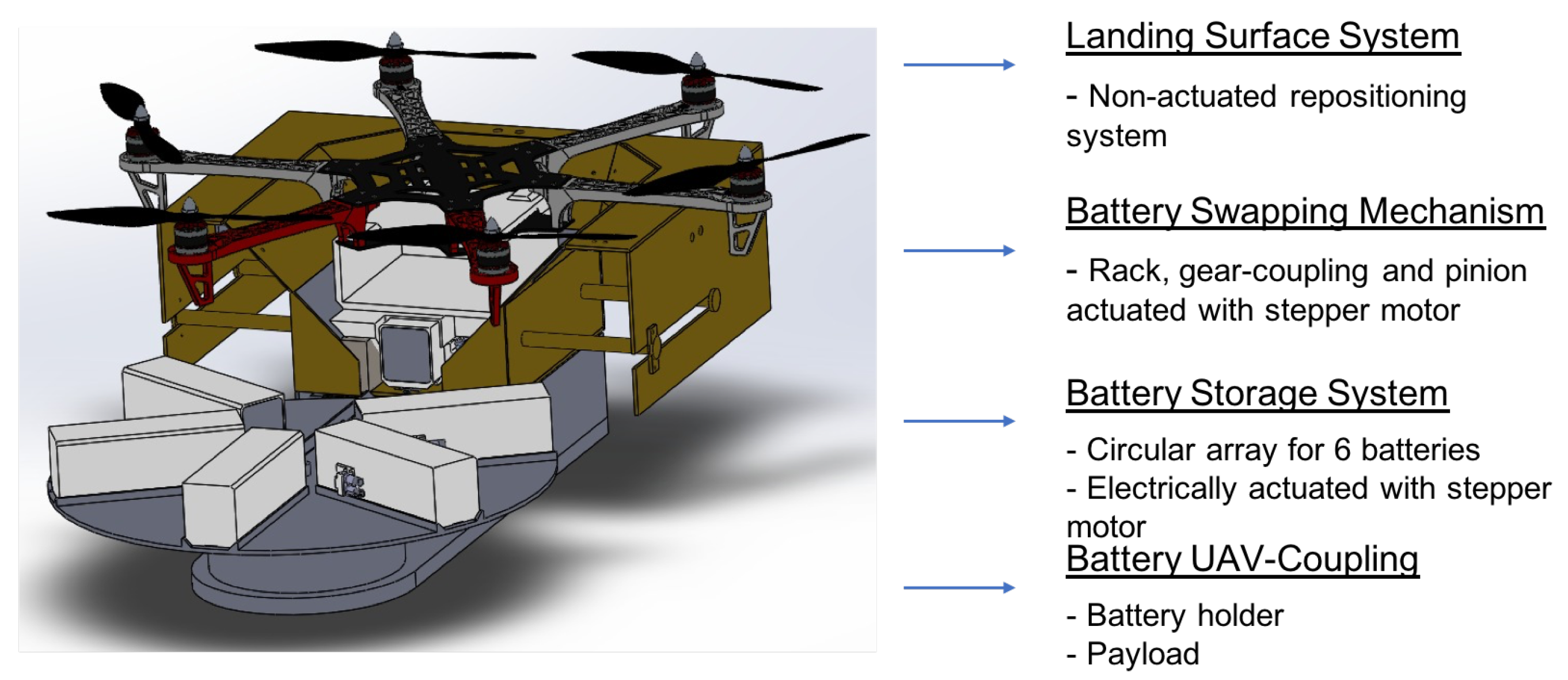
3. Ground Landing Station Design

In this section, a robotic sensing platform for UAVs is proposed. Figure 1 illustrates the design of the GLS structure. The modular design performs landing and battery replacement for UAVs. The system is based on a waterproof Nylamid–Polymer structure with epoxy resin in combination with steel, and it is comprised of four main modules: the Battery–UAV coupling, the swapping mechanism, the storage system, and the landing surface. The details of each subsystem are given in the next subsections.
The GLS can be adapted to a wide variety of UAVs; however, this model is designed based on the usage of a custom-made DJI Flamewheel hexacopter. The UAV is powered with a 6200 MAh LiPo battery with dimensions of 164 × 48 × 44 mm.

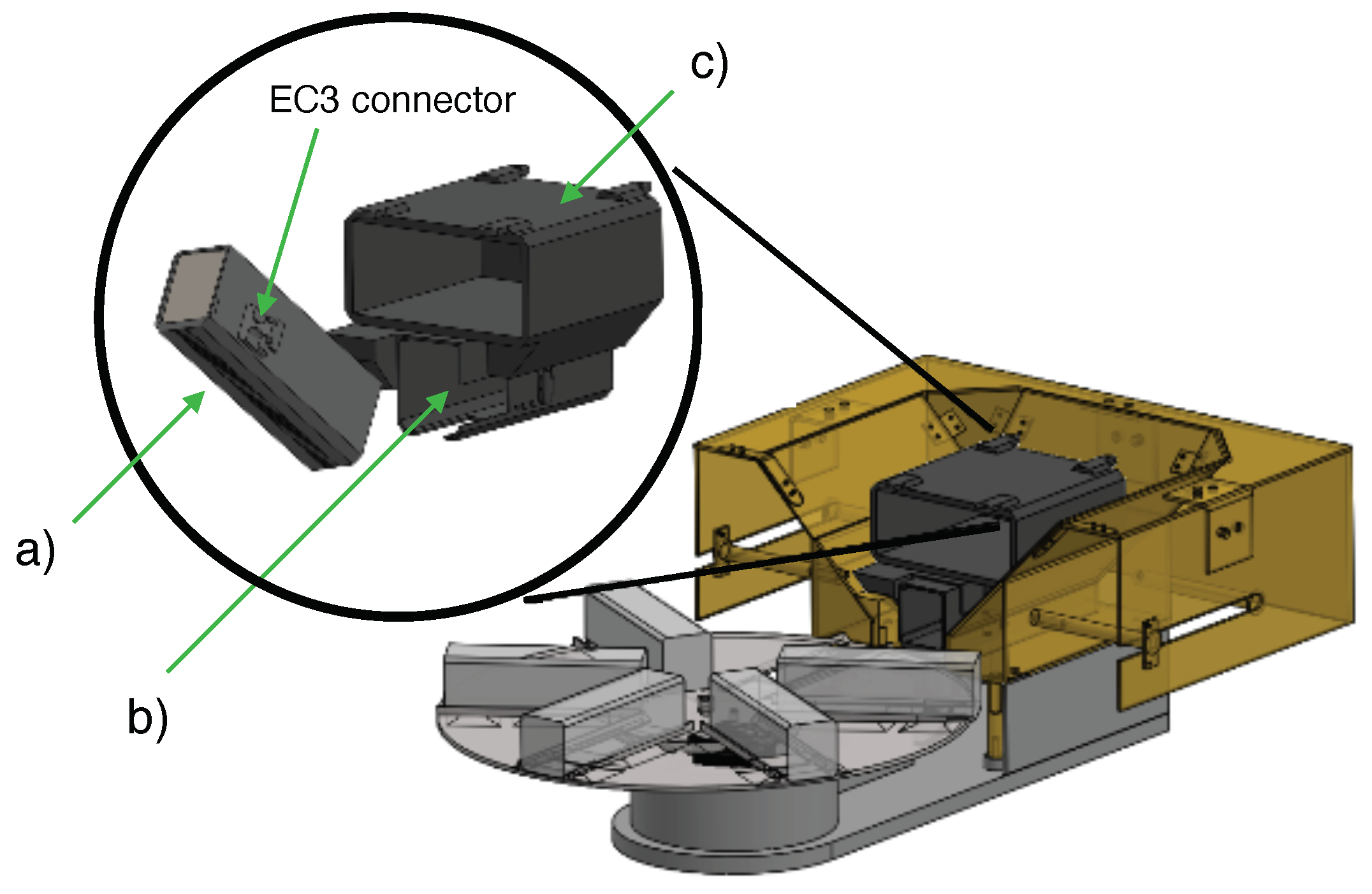
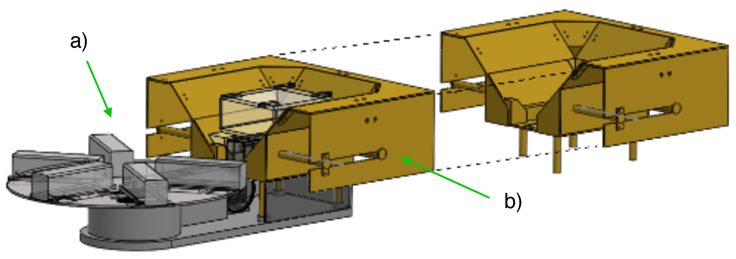
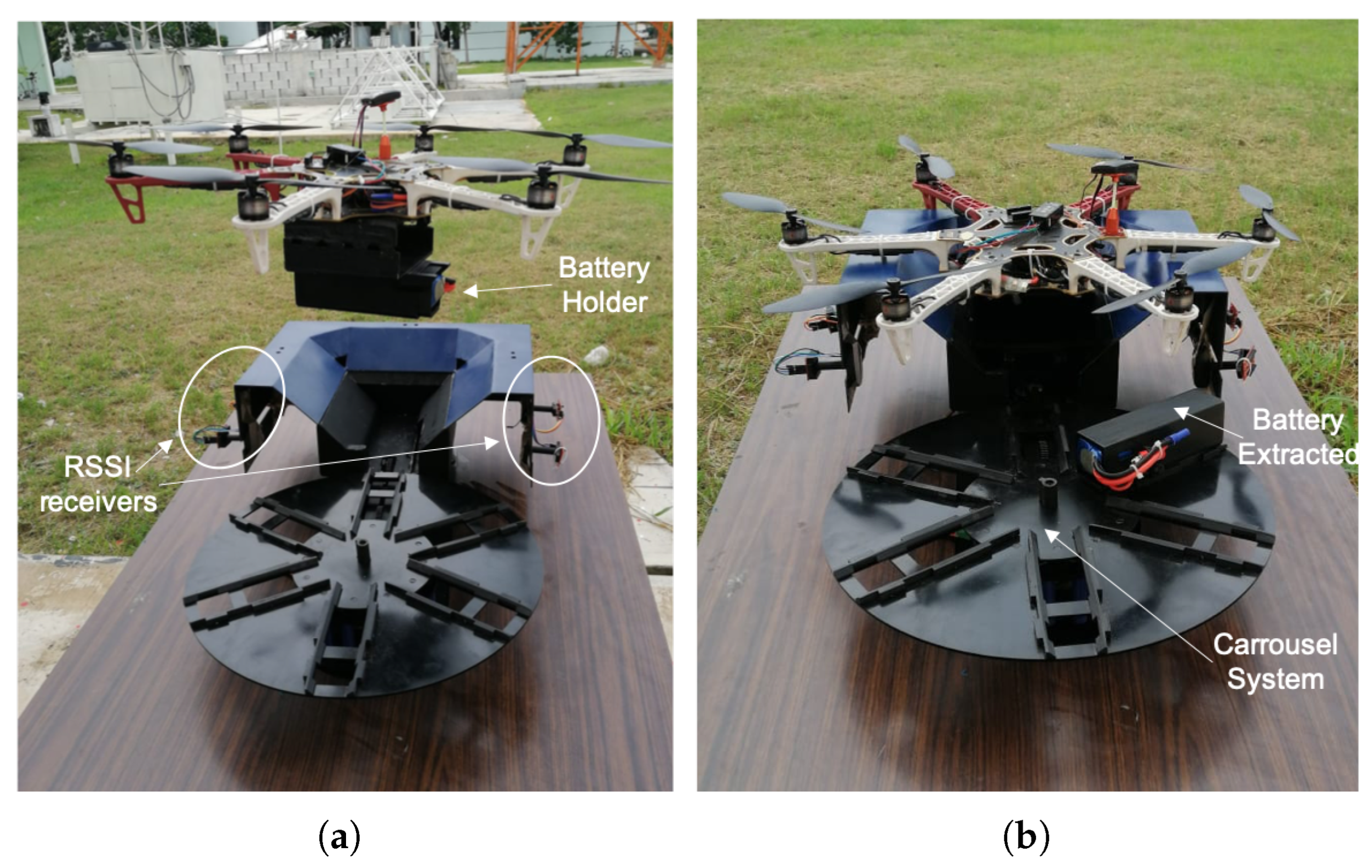
3.1. Battery–UAV Coupling System

Although a magnetic coupling system provides an efficient solution for battery replacement, the decoupling requires an external force that complicates the system design. In this study, a battery-carriage receiver and a battery holder are designed for UAV coupling, as shown in Figure 2.
The battery holder consists of a rectangular housing of 4 mm thick walls, and it can contain a 48 × 44 × 164 mm battery or any other type with smaller dimensions. The main feature of the battery holder is an EC3 connector on its outside right wall. Another characteristic is the rack design covering all the lengths of its bottom surface of 2 mm depth and 1 mm spacing. This design interfaces the pinion placed on the base of the battery swapping mechanism. When actuated, it moves the holder into or out of the carriage receiver. The receiver is placed underneath the UAV. It is composed of a payload box with dimensions of 138 × 141 × 56 mm and the battery carriage. An EC3 connector, attached on its right side, interacts with the connector on the battery holder. When the connectors are plugged in, the carriage is securely held inside the receiver.

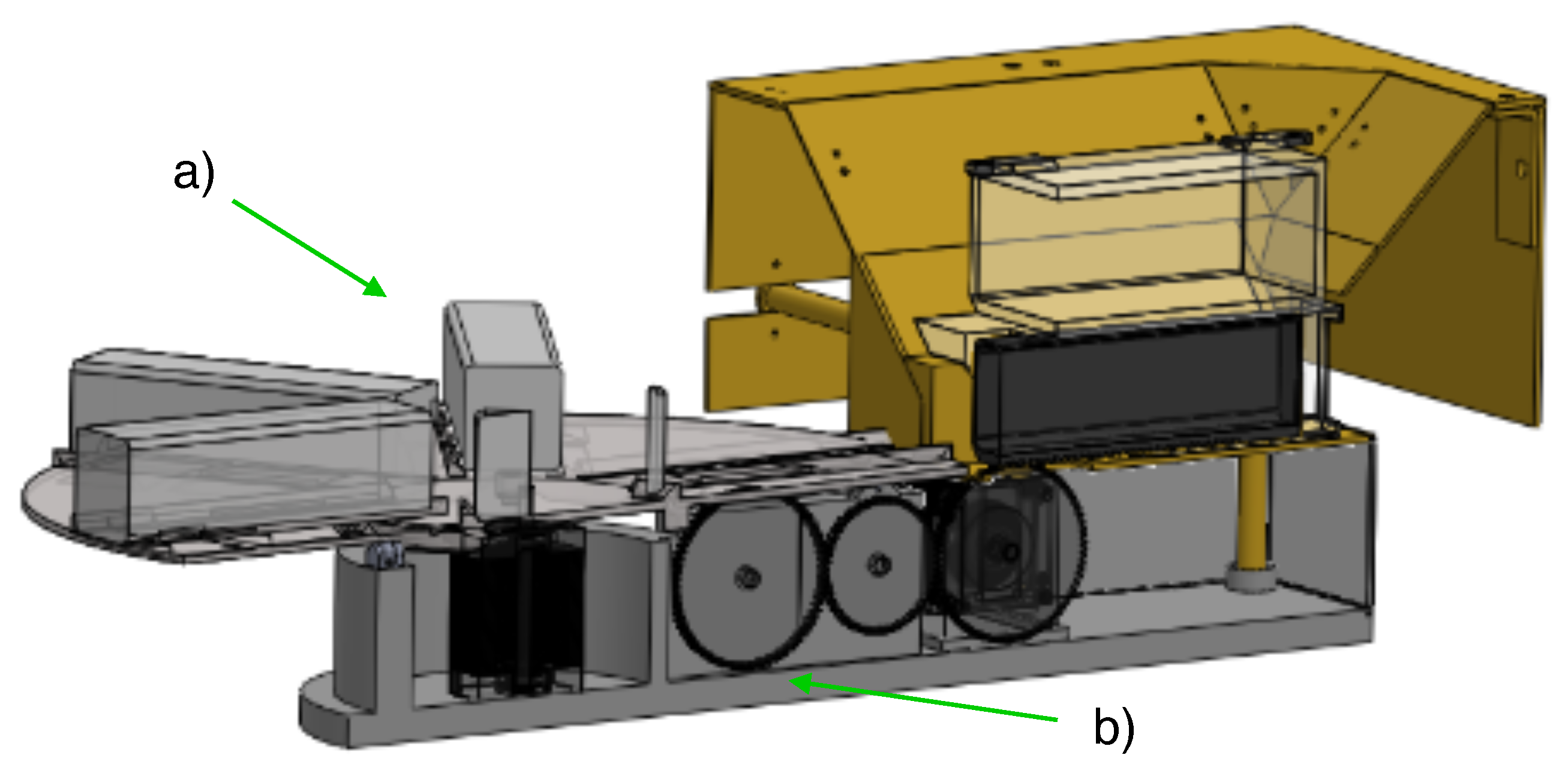
3.2. Battery Swapping Mechanism

The battery swapping mechanism is implemented by a rack, coupling gear, and pinion. The rack is on the bottom surface of the battery carriage while the pinion (82 mm diameter) is placed on the base and is directly actuated by a NEMA 32 stepper motor. The pinion also interfaces with a coupling gear and another pinion. This mechanism assures that the battery holder is moved from the receiver to the slots of the battery storage plate. Figure 3 illustrates the design of the battery swapping mechanism. The power consumption of the NEMA 32 stepper motor is supplied by a GLS energy battery source of 8000 mAh 2S2P, independent of the UAV battery. The consumption rate is 35.33 mAh, considering a period of 1 min per battery replacement with a typical current consumption of 2.12 A.

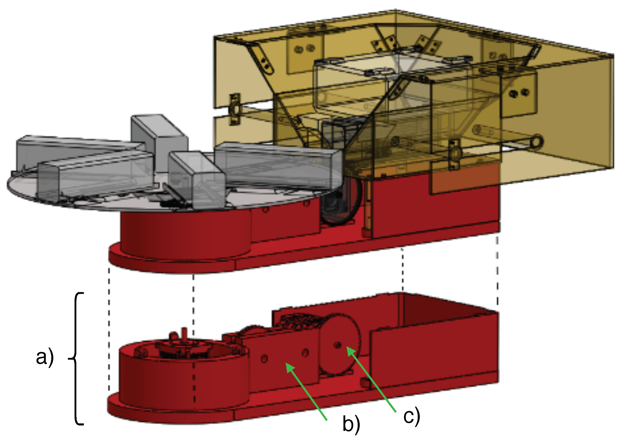
3.3. Battery Storage System

A horizontal circular battery array is used to replace the batteries. The proposed storage array is divided into two parts: a circular plate with battery slots and a mechanic base where the plate sits. The plate has six battery slots which consist of small slopes of 45 and 7 mm height, where the battery holders fit. The center and outermost parts of the slots are hollowed to let the battery swapping system work. Since one slot must always be empty to receive an incoming discharged battery, this means that the array can replace different batteries. The bottom side of the plate is a six-positioned carousel with a bearing guide, as seen in Figure 4.
As described in Figure 4, the bottom part of the battery storage system consists of a circular 20 mm thick wall with three wheels on top of it. The wheels are evenly distributed on the wall, meaning they are located at 120 from each other. In the center of the base, a NEMA 32 stepper motor is located, which directly rotates the plate.

3.4. Landing Surface

A non-actuated repositioning method is considered based on a sloped landing surface. Figure 5 shows the design divided into two parts: the bottom section is a base that matches the shape of the battery carriage receiver and the payload compartment attached to the UAV.
The top section is a sloped surface, which extends the base shape; it measures 440 mm in length and 315 mm in height, giving a landing area of 0.14 m 2 . The bottom part has four arms with a 12.7 mm (0.5 in) diameter, on its left and two on its right side; these arms hold securely the top part, which can be easily removed and replaced with a larger surface. The slope presents a 45 angle. At the top end of the slope, there is a flat surface where the UAV arms rest when docked.

4. Electronic Sensing Design for MLE-Based Position Estimation

The hardware electronics of the positioning system consists of a network of BLE modules. One node is attached to the UAV, transmitting its state. The other four sensing nodes are located in the corners of the GLS, receiving the RSSI-BLE signals from the UAV. Below, the UAV’s module will be referred to as the rover, while the modules on the GLS will be referred to as sensing modules.
The electronic platform selected for the UAV target position is the CY8CKIT-143A and the CY8CKIT-042-BLE-A interface boards. The rover operates autonomously, and the base station sensing modules are interconnected in a master–slave fashion using the I2C protocol. The master controller module (see Figure 6) receives the information from the A, B, C, and D sensing modules on the corners of the GLS landing platform. This information is transmitted to a PC with the universal asynchronous receiver–transmitter (UART) protocol.

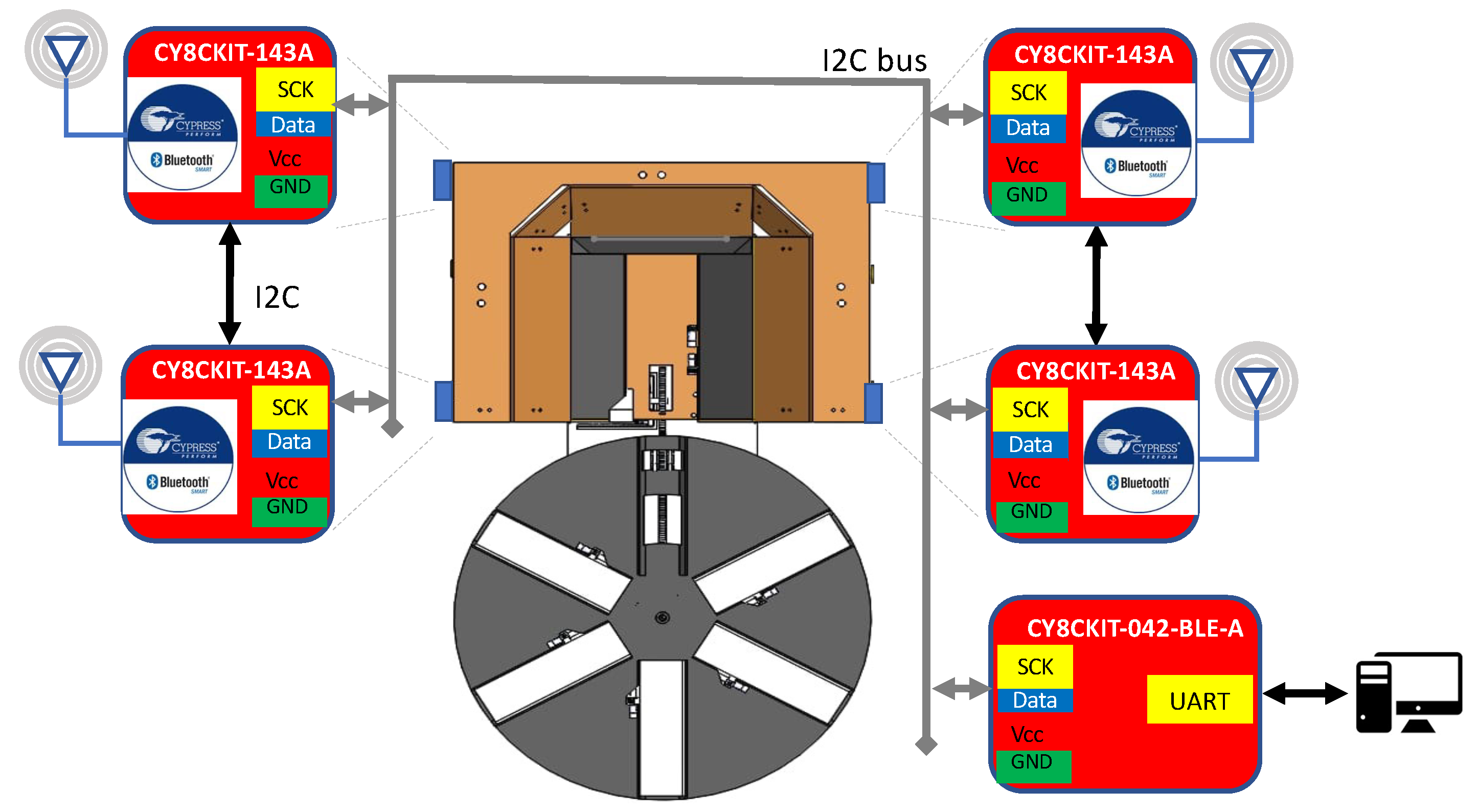
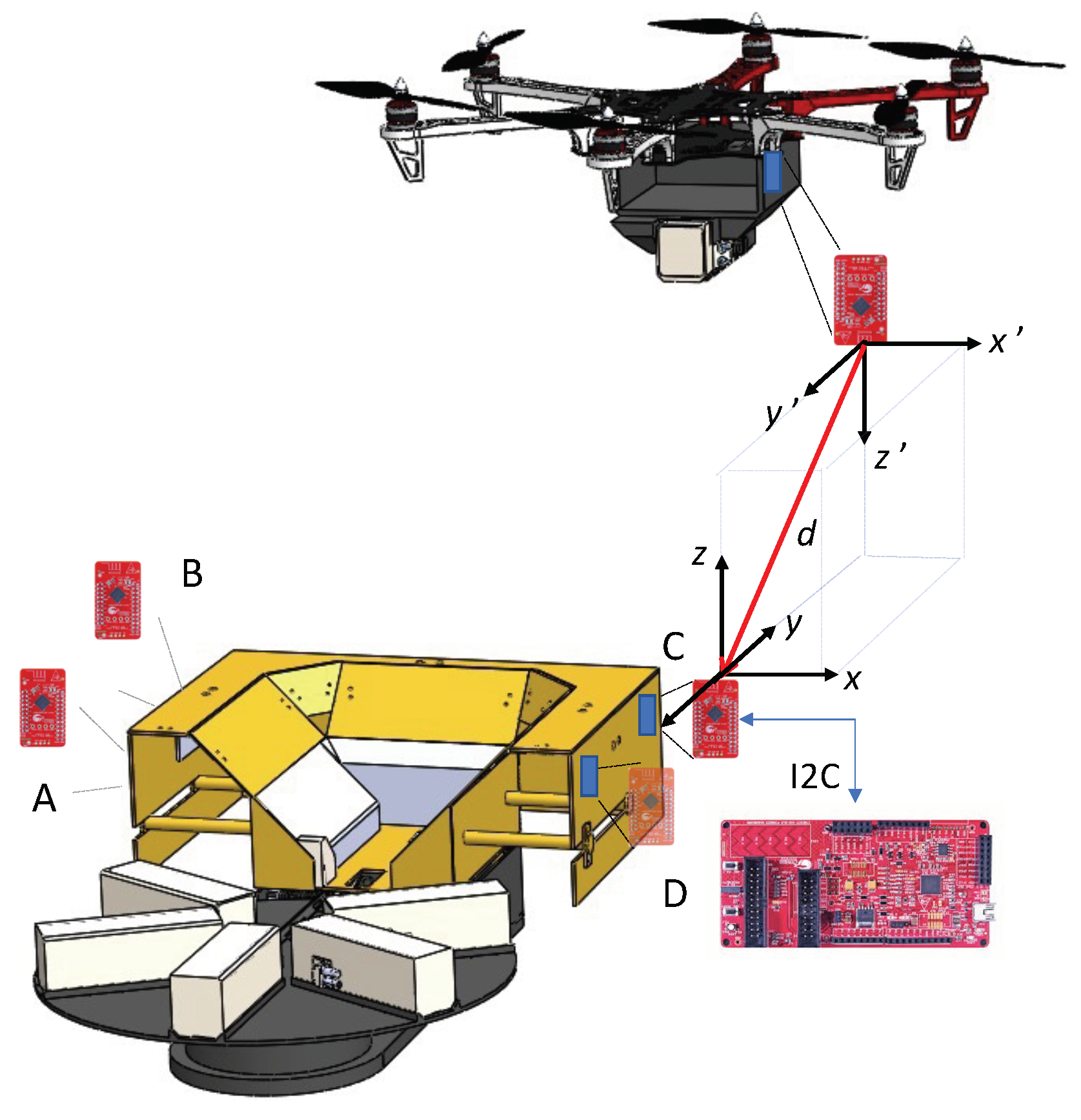
4.1. Electronic HW Configuration

The CY8CKIT-143A module incorporates the Bluetooth Core Specification v4.2 compliant protocol stack and provides a set of application programming interfaces (APIs) for user configurations. In this regard, the Generic Access Profile (GAP) is a procedure related to locating other Bluetooth devices and provides link management aspects for interconnection. Four roles are defined with this profile, i.e., Broadcaster, Observer, Peripheral and Central. In another aspect, the Generic Attribute Profile (GATT) API provides a service framework using the ATT protocol layer for Client/Server configurations. The GATT Client receives the data and initiates commands and requests toward the GATT Server. It also receives responses, indications, and data notifications by the server. Likewise, the rover module is configured in advertising state, and the sensing modules are configured as a GAP peripheral and GATT client.
Two API functions perform the switching states in the sensing modules and the rover. HandleBleProcessing(·) performs the function of switching between scanning and disconnected states for the sensing modules, and for the rover, it switches the state from disconnected to advertising. The function CyBle_ProcessEvents(·) checks the internal task queue in the BLE Stack and returns an advertisement response package. If the package is correctly received, the sensing module proceeds to obtain the RSSI readings by calling the function CyBle_GetRssi(·), which returns an RSSI value for the last successfully received packet from the rover.

4.2. MLE Position Estimation Algorithm

To estimate the position of the UAV with respect to the base, an array of 0 i I 1 base modules in the GLS and a transmitter mounted in the UAV are used as illustrated in Figure 7. These devices are capable of detecting the strength of the signal propagated for the transmitter such that it is possible to estimate the distance between the UAV and each base module and subsequently, through trilateration, infer its position in the space.
To achieve this goal, it is assumed the RSSI attenuation model is as follows
P ( d ) = A 10 β log 10 ( d ) + ω
where P ( d ) is the signal power in dB, d is the distance in meters between UAV and GLS, A and β are constants that depend on the propagation medium, which can be estimated during an initialization process, and ω is a zero-mean Gaussian random variable with variance σ 2 . Thereby, to perform the position estimation for each sensing module, the power is sensed periodically to obtain an array of N samples. This array can be expressed using (1) as follows:
p i [ n ] = A 10 β log 10 ( d 0 i + n Δ i ) + ω i [ n ]
where 0 n N 1 is an index that enumerates the samples, p i [ n ] is the signal power measured by the i-th base module at instant n, d 0 i is the distance between the transmitter and the i-th base module at instant n = 0 and Δ i is the speed in meters per sample. The power signal p i [ n ] is a stochastic process that depends on the initial distance d 0 i and the speed Δ i , which are the values to be estimated. Assuming independent and identically distributed samples ω i [ n ] , the joint probability density function (PDF) is:
f i ( d 0 i , Δ i ) = 1 ( 2 π σ 2 ) N / 2 exp 1 2 σ 2 n = 0 N 1 ( p i [ n ] γ i ) 2
where γ i = A 10 β log 10 ( d 0 i + n Δ i ) .
The estimation process is performed with the Maximum Likelihood Estimator (MLE) algorithm. This algorithm searches the parameters of interest to maximize the joint PDF of the sample array when it is evaluated with the acquired samples. This is equivalent to minimizing, with respect to d 0 i and Δ i , the log-likelihood function of (3)
J i ( d 0 i , Δ d i ) = n = 0 N 1 ( p i [ n ] γ i ) 2 .
In order to achieve this minimal, the iterative Newton–Raphson method is implemented as follows:
θ i [ k + 1 ] = θ i [ k ] H 1 ( θ i [ k ] ) g ( θ i [ k ] )
where θ i [ k ] = [ d ^ 0 i , Δ ^ i ] T is the vector containing the estimated values of d 0 i and Δ i at the k-th iteration, H ( θ i [ k ] ) is the Hessian matrix of J i evaluated in θ i [ k ] and g ( θ i [ k ] ) is the gradient of J i evaluated in θ i [ k ] . The aforementioned Hessian matrix and gradient vector are given by:
(6) H ( θ ) = n = 0 N 1 α p ¯ i [ n ] δ 2 n = 0 N 1 n α p ¯ i [ n ] δ 2 n = 0 N 1 n α p ¯ i [ n ] δ 2 n = 0 N 1 n 2 α p ¯ i [ n ] δ 2 (7) g ( θ ) = n = 0 N 1 α p ¯ i [ n ] δ n = 0 N 1 n α p ¯ i [ n ] δ
where p ¯ i [ n ] = p i [ n ] γ i , α = 10 β log 10 ( e ) and δ = d 0 i + n Δ i . This iterative process is carried out for each base module i, beginning each process with the initial value θ i [ 0 ] = [ 0 , 0 ] T and finishing when | θ i [ k + 1 ] θ i [ k ] | ϵ for a predefined error ϵ . Once all the parameters have been estimated, the distance from the i-th base module to the UAV is given by:
d i = d 0 i + N Δ i .
These distances facilitate the estimation of the UAV position using trilateration. This assumes that the antennas used in the base modules and in the rover have an isotropic radiation pattern, such that:
d i 2 = ( x 1 c 1 i ) 2 + ( x 2 c 2 i ) 2 + ( x 3 c 3 i ) 2 .
These devices are capable of detecting the strength of the signal propagated by the transmitter, which is used to estimate the distance between the UAV and each base module, and subsequently, through trilateration, infer its position in the space, as follows:
x [ k + 1 ] = x [ k ] J ( x [ k ] ) F ( x [ k ] )
where x [ k ] is the estimated value of x at iteration k, F ( x [ k ] ) = [ F 0 ( x ) , , F I 1 ( x ) ] T for x = x [ k ] , J ( x [ k ] ) is the Jacobian matrix of F ( x ) evaluated in x [ k ] and ( · ) is the pseudoinverse operator. This iterative process finishes when | x [ k + 1 ] x [ k ] | ϵ 1 for a given error ϵ 1 .

5. Experimental Results

Experimental analysis was conducted using real-time RSSI-BLE measurements to evaluate the MLE algorithm implemented on the CY8CKIT-042-BLE-A for target position estimation. Figure 8 shows the proposed GLS prototype for UAV landing.
The test methodology is the following: a flight mission was realized to prove the feasibility of the GLS. This test corroborates the GLS functionality and the accuracy of the UAV position estimation. A flying test area with a radius of 5 m was established. If the UAV is outside this area, it is controlled with a GPS device for autonomous navigation. Otherwise, the network of four PSOC-BLE devices will compute the RSSI signals from the master module for target localization. The slave modules on the GLS are named A, B, C, D, and the master module is located in the UAV.

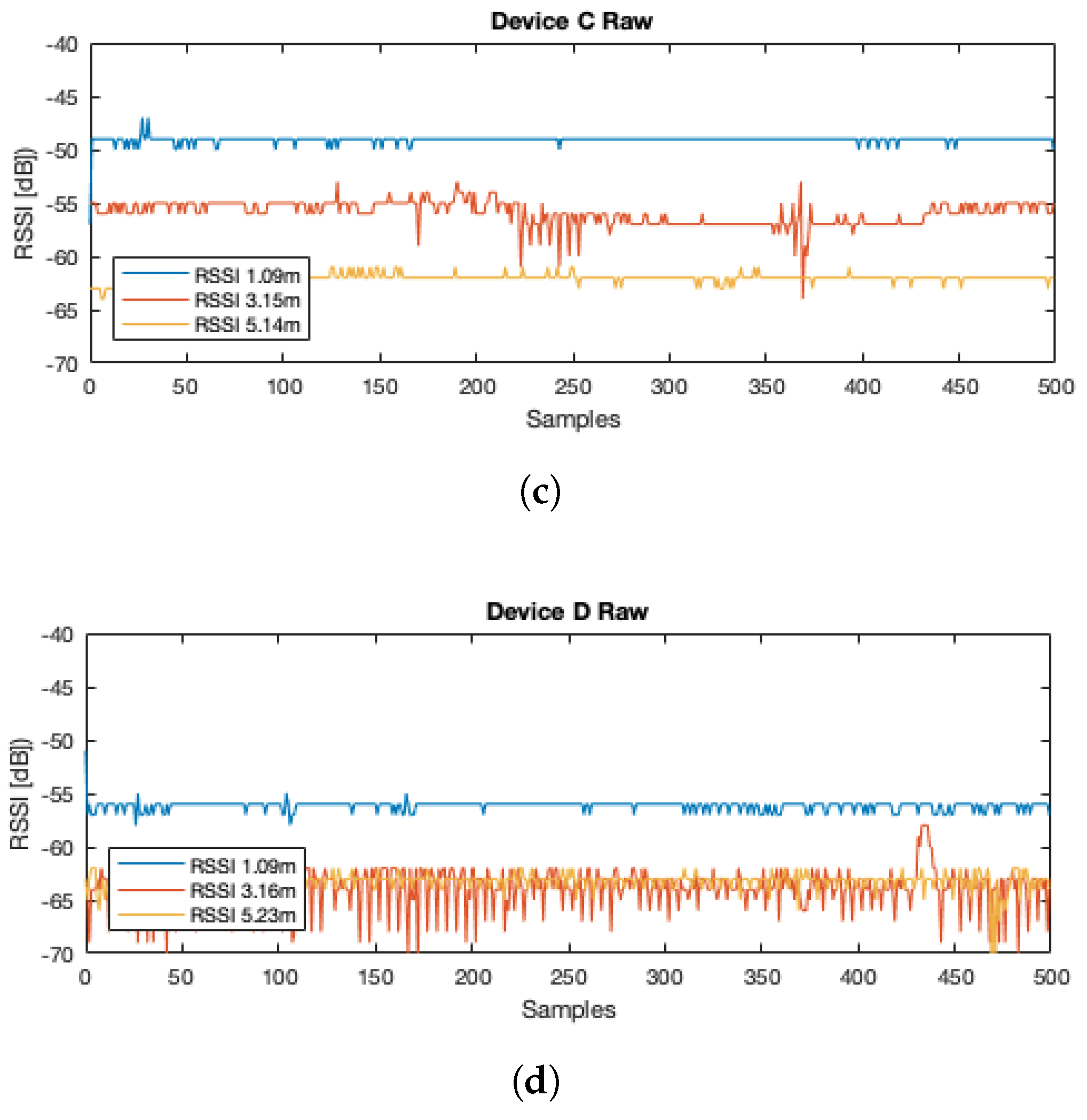
5.1. RSSI Attenuation and Digital Filtering Analysis

The effectiveness of the logarithmic attenuation model and the algorithm implementation for target localization is demonstrated at different distances. As the first step, the model parameters β = 2.466 and A = 60.214 were computed from RSSI measurements by considering a 1 m distance between the transmitter and receivers. Likewise, a fifth-order Butterworth digital filter was implemented with a cutoff frequency of W n = 100 Hz in order to smooth the RSSI signal.
Figure 9 illustrates the raw RSSI data from the rover to each module A, B, C, and D at three different distances: 1 , 3 and 5 m. In this test, each one of the sensing modules individually acquires its respective RSSI data.
Once the RSSI data were measured, the logarithmic attenuation model is computed, and the distance from the rover to each sensing node of the PSOC-BLE network is also verfied. Figure 10 shows the resulting estimated position of each sensing module A, B, C, and D, which are located on each corner of the GLS.
As can be seen in the data, if the distance is closer between the UAV and the landing platform, the error is reduced. Therefore, better results are achieved when the UAV is close to the GLS system.

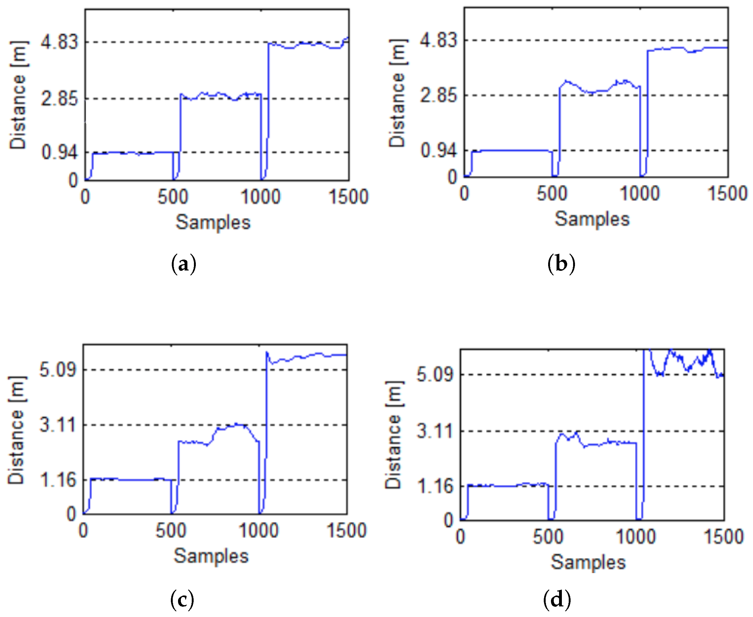
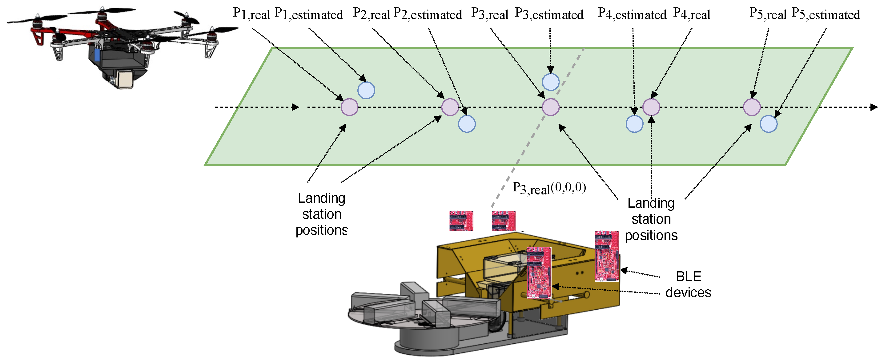
5.2. MLE Target Position Estimation

The conceptual test idea for the on-fly UAV position localization is shown in Figure 11. In this case study, the distance from the i th base module to the UAV is computed using (8), and then, the position of the UAV x = [ x 1 , x 2 , x 3 ] T is estimated using (10) for the fixed position of the GLS. The Cartesian coordinates of each of the base modules located in the GLS are the following: A = ( 0 , 0 , 0 ) , B = ( 0 , 0.26 , 0 ) , C = ( 0.55 , 0.26 , 0 ) and D = ( 0.55 , 0 , 0 ) . The UAV follows a straight trajectory with continuous speed, and at the same altitude, i.e., 0.5 m from the GLS, as illustrated in Figure 11.
Table 1 summarizes a comparative analysis of the UAV’s estimated position with their real position and the resulting error at each Cartesian coordinate.

6. Discussion

In this study, the design and fabrication of an inexpensive GLS system are proposed. The GLS is assembled with acrylic, nylamid, Polylactic Acid Thermoplastic, and a 2 mm thick steel sheet, as illustrated in Figure 2, Figure 3, Figure 4 and Figure 5. As shown in Figure 9, RSSI signals are affected by reflections, absorption, and degradation. The studies in [22,23] proposed statistical filters and other signal processing methods, such as particle filters in [24]. However, to estimate the position, multiple successive iterations are necessary.
As noticed in Table 1 and Figure 9, Figure 10 and Figure 11, large errors are detected when the UAV is outside a 5 m radius to the GLS. Therefore, GPS is suggested even with its lack of accuracy for navigation at these relatively large distances. Inside the radius, the error is continuously reduced when the UAV approaches the GLS. The proposed MLE algorithm, in combination with the filtered RSSI data and the trilateration algorithm, achieves average errors of less than 0.04 m when the UAV is less than 0.5 m from the GLS.
Table 2 also shows a comparative analysis with similar GLS systems and RSSI-based UAV target position estimation. Refs. [17,25] show good position estimation results with errors of 0.78 and 0.70 m, respectively. However, these systems do not consider a GLS design. An accurate system with an error of only 0.001 m was achieved by [11]. The main disadvantage of this system is that complex actuated mechanisms, as well as infrared filters and expensive vision systems, are used. The presented approach finds a good balance between GLS design and the target position estimation accuracy, achieving average errors of less than 0.04 m.
There is no standard test or set of testing conditions for evaluation of accuracy of UAV docking procedures. This is due to the fact that there are such a large variety of UAV types and also many different docking mechanisms and processes. That being said, it is clear that for small UAVs with rotor spans less than 4 meters, an accuracy two orders of magnitude less than the rotor span would be very beneficial for most docking processes.

7. Conclusions

In this paper, a ground landing station prototype for UAV landing based on BLE-RSSI and a maximum likelihood position estimation algorithm was presented. The prototype was designed and fabricated using a combination of an inexpensive 3D printing, cutting and bending steel sheet, and acrylic. The fused MLE and trilateration algorithms were tested for different UAV distances to the GLS. Measurement results demonstrate that the BLE-RSSI network accurately locates the target when the UAV remains inside a radius of 5 m from the GLS platform.

Author Contributions

Conceptualization, J.A.-V.; Formal analysis, R.C.-A.; Investigation, J.V.-C.; Methodology, J.O.-A.; Software, R.P.-E.; Supervision, D.D.J.; Validation, J.J.E.-L.; Writing—review & editing, A.C.-A. All authors have read and agreed to the published version of the manuscript.

Funding

This research received no external funding.

Institutional Review Board Statement

Not applicable.

Informed Consent Statement

Not applicable.

Data Availability Statement

Not applicable.

Conflicts of Interest

The authors declare no conflict of interest.

References

  1. Uddin, M.A.; Mansour, A.; Jeune, D.L.; Ayaz, M.; Aggoune, E.-H. UAV-Assisted Dynamic Clustering of Wireless Sensor Networks for Crop Health Monitoring. Sensors 2018, 18, 555. [Google Scholar] [CrossRef] [PubMed] [Green Version]
  2. Hayajneh, M.; Melega, M.; Marconi, L. Design of autonomous smartphone based quadrotor and implementation of navigation and guidance systems. Mechatronics 2018, 49, 119–133. [Google Scholar] [CrossRef]
  3. Liao, Y.-H.; Juang, J.-G. Real-Time UAV Trash Monitoring System. Appl. Sci. 2022, 12, 1838. [Google Scholar] [CrossRef]
  4. Aslan, M.F.; Durdu, A.; Sabanci, K.; Ropelewska, E.; Gültekin, S.S. A Comprehensive Survey of the Recent Studies with UAV for Precision Agriculture in Open Fields and Greenhouses. Appl. Sci. 2022, 12, 1047. [Google Scholar] [CrossRef]
  5. Shi, W.; Zhou, H.; Li, J.; Xu, W.; Zhang, N.; Shen, X. Drone Assisted Vehicular Networks: Architecture, Challenges and Opportunities. IEEE Netw. 2018, 32, 130–137. [Google Scholar] [CrossRef]
  6. Abeywickrama, H.V.; Jayawickrama, B.A.; He, Y.; Dutkiewicz, E. Comprehensive Energy Consumption Model for Unmanned Aerial Vehicles, Based on Empirical Studies of Battery Performance. IEEE Access 2018, 6, 58383–58394. [Google Scholar] [CrossRef]
  7. Sang-Won, K.; In-Kui, C.; Sung-Yong, H. Comparison of charging region differences according to receiver structure in drone wireless charging system. In Proceedings of the International Conference on Information and Communication Technology Convergence (ICTC), Jeju Island, Korea, 20–22 October 2017; pp. 1058–1060. [Google Scholar] [CrossRef]
  8. Barrett, E.; Reiling, M.; Mirhassani, S.; Meijering, R.; Jager, J.; Mimmo, N.; Callegati, F.; Marconi, L.; Carloni, R.; Stramigioli, S. Autonomous Battery Exchange of UAVs with a Mobile Ground Base. In Proceedings of the IEEE International Conference on Robotics and Automation (ICRA), Brisbane, Australia, 21–25 May 2018; pp. 699–705. [Google Scholar]
  9. Zhou, S.; Pollard, J.K. Position measurement using Bluetooth. IEEE Trans. Consum. Electron. 2006, 52, 555–558. [Google Scholar] [CrossRef]
  10. Wang, J.; Park, J.G. A Novel Indoor Ranging Algorithm Based on a Received Signal Strength Indicator and Channel State Information Using an Extended Kalman Filter. Appl. Sci. 2020, 10, 3687. [Google Scholar] [CrossRef]
  11. Fujii, K.; Higuchi, K.; Rekimoto, J. Endless Flyer: A Continuous Flying Drone with Automatic Battery Replacement. In Proceedings of the IEEE 10th International Conference on Ubiquitous Intelligence & Computing and IEEE 10th International Conference on Autonomic & Trusted Computing (UIC/ATC), Vietri sul Mare, Italy, 18–21 December 2013; pp. 216–223. [Google Scholar] [CrossRef]
  12. Ure, N.K.; Chowdhary, G.; Toksoz, T.; How, J.P.; Vavrina, M.A.; Vian, J. An Automated Battery Management System to Enable Persistent Missions with Multiple Aerial Vehicles. IEEE/ASME Trans. Mechatron. 2015, 20, 275–286. [Google Scholar] [CrossRef]
  13. Lin, Q.; Son, J. Analysis of Bluetooth RSSI for Proximity Detection of Ship Passengers. Appl. Sci. 2022, 12, 517. [Google Scholar] [CrossRef]
  14. Swieringa, K.A.; Hanson, C.B.; Richardson, J.R.; White, J.D.; Hasan, Z.; Qian, E.; Girard, A. Autonomous battery swapping system for small-scale helicopters. In Proceedings of the IEEE International Conference on Robotics and Automation, Anchorage, AK, USA, 3–7 May 2010; pp. 3335–3340. [Google Scholar] [CrossRef]
  15. Lee, D.; Zhou, J.; Lin, W.T. Autonomous battery swapping system for quadcopter. In Proceedings of the International Conference on Unmanned Aircraft Systems (ICUAS), Denver, CO, USA, 9–12 June 2015; pp. 118–124. [Google Scholar] [CrossRef]
  16. Choi, C.H.; Jang, H.J.; Lim, S.G.; Lim, H.C.; Cho, S.H.; Gaponov, I. Automatic wireless drone charging station creating essential environment for continuous drone operation. In Proceedings of the International Conference on Control, Automation and Information Sciences (ICCAIS), Ansan, Korea, 27–29 October 2016; pp. 132–136. [Google Scholar] [CrossRef]
  17. Li, G.; Geng, E.; Ye, Z.; Xu, Y.; Lin, J.; Pang, Y. Indoor Positioning Algorithm Based on the Improved RSSI Distance Model. Sensors 2018, 18, 2820. [Google Scholar] [CrossRef] [PubMed] [Green Version]
  18. Gu, Y.; Quan, L.; Ren, F.; Li, J. Fast Indoor Localization of Smart Hand-Held Devices Using Bluetooth. In Proceedings of the 10th International Conference on Mobile Ad-hoc and Sensor Networks, Maui, HI, USA, 19–21 December 2014; pp. 186–194. [Google Scholar] [CrossRef]
  19. Contreras, D.; Castro, M.; Torre, D. Performance evaluation of bluetooth low energy in indoor positioning systems. Trans. Emerg. Telecommun. Technol. 2017, 28, e2864. [Google Scholar] [CrossRef] [Green Version]
  20. Jianyong, Z.; Haiyong, L.; Zili, C.; Zhaohui, L. RSSI based Bluetooth low energy indoor positioning. In Proceedings of the International Conference on Indoor Positioning and Indoor Navigation (IPIN), Busan, Korea, 27–30 October 2014; pp. 526–533. [Google Scholar] [CrossRef]
  21. Rodas, J.; Fernandez, T.M.; Iglesia, D.I.; Escudero, C.J. Multiple Antennas Bluetooth System for RSSI Stabilization. In Proceedings of the 4th International Symposium on Wireless Communication Systems, Trondheim, Norway, 17–19 October 2007; pp. 652–656. [Google Scholar] [CrossRef]
  22. Roonizi, A.K. l2 and l1 Trend Filtering: A Kalman Filter Approach [Lecture Notes]. IEEE Signal Process. Mag. 2021, 38, 137–145. [Google Scholar] [CrossRef]
  23. Li, K.; Príncipe, J.C. Functional Bayesian Filter. IEEE Trans. Signal Process. 2022, 70, 57–71. [Google Scholar] [CrossRef]
  24. Elvira, V.; Miguez, J.; Djurić, P.M. On the performance of particle filters with adaptive number of particles. Stat. Comput. 2021, 31, 81. [Google Scholar] [CrossRef]
  25. Wang, S. Wireless Network Indoor Positioning Method Using Nonmetric Multidimensional Scaling and RSSI in the Internet of Things Environment. Math. Probl. Eng. 2020, 2020, 8830891. [Google Scholar] [CrossRef]
Figure 1. Robotic ground-station structure.
Applsci 12 06618 g001
Figure 2. Battery coupling system: (a) holder, (b) receiver and (c) paylod.
Applsci 12 06618 g002
Figure 3. Battery swapping mechanism design: (a) rack, (b) coupling gear, and (c) pinion.
Applsci 12 06618 g003
Figure 4. Battery storage design for UAV ground station: (a) circular battery array, and (b) mechanic base.
Applsci 12 06618 g004
Figure 5. Non-actuated landing surface design: (a) battery storage and (b) sloped landing surface.
Applsci 12 06618 g005
Figure 6. Schematic design of the HW sensing ground station.
Applsci 12 06618 g006
Figure 7. Conceptual RSSI target position of each base module.
Applsci 12 06618 g007
Figure 8. GLS integrated with electronic RSSI-BLE receivers: (a) UAV approaching to the GLS, (b) UAV with battery replaced.
Applsci 12 06618 g008
Figure 9. RSSI measurements of three UAV positions for each sensing module: (a) Raw data device A, (b) Raw data device B, (c) Raw data device C, and (d) Raw data device D.
Applsci 12 06618 g009aApplsci 12 06618 g009b
Figure 10. Results of the distance estimation analysis: (a) from three different distances of the UAV to sensing module A, (b) the same distances of the UAV to sensing module B, (c) results of the distance estimation from UAV to sensing module C, and (d) UAV to sensing module D.
Applsci 12 06618 g010
Figure 11. MLE-based target position estimation test.
Applsci 12 06618 g011
Table 1. MLE target estimation results.
UAV Position CoordinatesEstimated PositionError
P 1 (m)
(−4.0, 0.1, 0.5)( 3.39 , 0.24 , 0.27)(0.61, 0.34, 0.23)
P 2 (m)
(−2.0, 0.1, 0.5)( 1.80 , 0.13 , 0.25)(0.20, 0.23, 0.25)
P 3 (m)
(−0.5, 0.1, 0.5)( 0.69 , 0.06, 0.36)(0.19, 0.04, 0.14)
P 4 (m)
(1.5, 0.1, 0.5)(1.33, 0.16 , 0.33)(0.17, 0.26, 0.17)
P 5 (m)
(3.0, 0.1, 0.5)(3.40, 0.42, 0.86)(0.40, 0.32, 0.36)
Table 2. Comparative analysis of ground landing stations and target position estimation for UAVs.
[11][12][22][10][17][25]This
Work
GLS
structure
L-shape
robotic
arms
Dual-drum
structure
Non-actuated
landing
surface
Filtering
method
Infrared
filters
l 2 l 1
LTI filter
Extended
Kalman
filter
Particle
swarm
optimization
Gaussian
filter
Butterworth
digital
filter
Hardware
detection
Vision
system
Vision
system
RSSI-BLERSSI-BLERSSI-BLERSSI-BLE
Estimation
algorithm
Markov
decision
process
Piecewise
polynomial
RSSI-CSI
algorithm
Back-propagation
neural network
Nonmetric
multidimensional
scaling
MLE
algorithm
Error
(m)
0.0011.040.780.700.04
Publisher’s Note: MDPI stays neutral with regard to jurisdictional claims in published maps and institutional affiliations.

