1. Introduction
At present, the supercritical carbon dioxide (S-CO
2) Brayton cycle system, instead of the traditional steam Rankine cycle system, shows great potential in improving the photoelectric conversion efficiency of the system and reducing the power generation cost. S-CO
2 Brayton cycle power generation technology, with its significant technological and performance advantages, has considerable application potential in the utilization of ship flue gas waste heat, which is a critical way to improve the green level of ships and realize energy conservation and emission reduction in the shipping industry [
1,
2,
3]. As one of the core components of the system, the S-CO
2 heat exchange precooler influences the system circulation efficiency. The printed circuit heat exchanger (PCHE) is considered the ideal S-CO
2 high-efficiency heat exchanger in the system due to its advantages of pressure reduction, large heat exchange area, good compactness, high heat exchange efficiency, and proper operation under high-intensity conditions [
4].
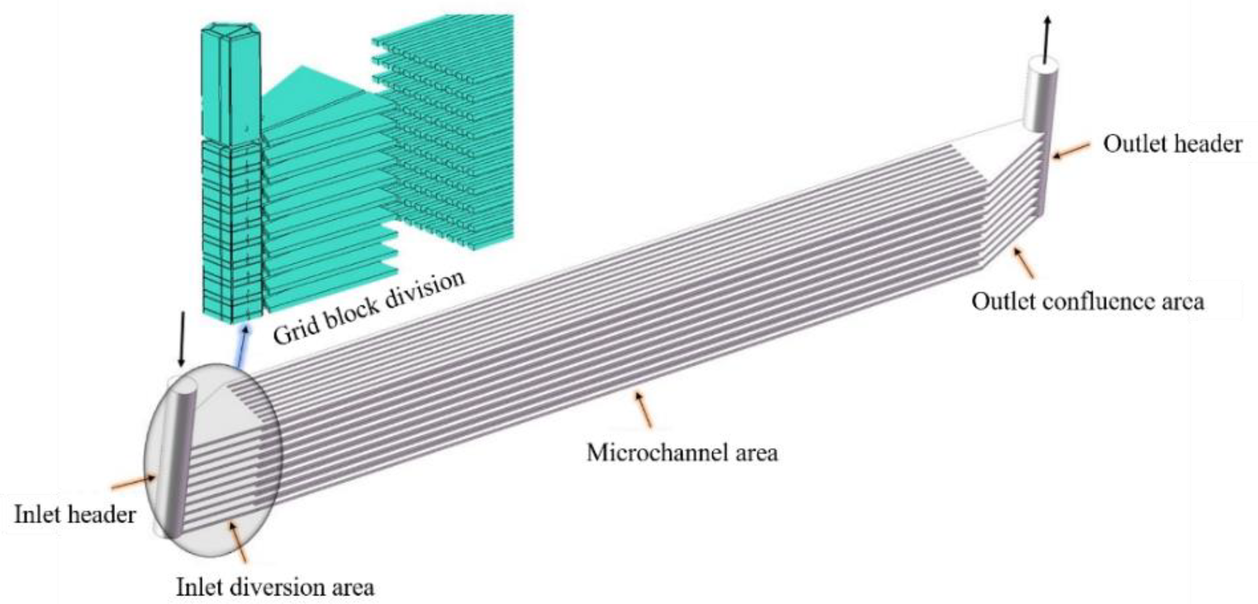
The PCHE, which is a typical representative of a microchannel heat exchanger, contains hundreds of microchannels, and whether the flow in each microchannel is evenly distributed has a significant influence on the heat transfer characteristics of the PCHE. In addition, considering that the physical properties of S-CO
2 (density, specific heat, viscosity, thermal conductivity, etc.) change with temperature, the flow state of S-CO
2 in the flow channel will also be affected [
5,
6]. Therefore, the study of flow allocation in microchannels of the PCHE is of great significance.
Most of the existing literature on PCHEs assumes that the flow distribution in the flow channels is uniform and that the operating condition is the steady state, ignoring the difference in the flow in the cross-section of the different flow channels and the influence of the inlet and outlet types on the flow distribution. An uneven flow distribution may lead to a decrease in the PCHE heat transfer performance. Pasquier [
7] studied the influence of four different inlet header types on the flow non-uniformity of PCHEs. Koo [
8] applied computational fluid dynamics (CFD) to optimize the mass flow rate distribution at the PCHE inlet, improving this distribution by 7.5%, eliminating the separation area near the surface, and reducing the pressure drop. Guo [
9] studied the flow and temperature in homogeneities at the inlet end of the cross-flow heat exchanger. Multichannel plate heat exchangers are recommended for efficient power and propulsion systems. Chu [
10] used a numerical simulation method to analyze the uneven distribution of large flow in the inlet header structure of high-temperature heat exchangers. Four kinds of improved intake headers were proposed, including an inclined baffle, a segmental baffle, a spiral baffle, and an improved spiral baffle. The results showed that all the proposed designs more or less improve the uniform flow distribution between the channels. Chu [
11] analyzed four different inlet headers and proposed an improved header that significantly reduced flow inhomogeneity. Ma [
12] established a new prediction model to predict the uneven flow distribution in PCHEs and found that an increase in the channel length could improve the uneven flow distribution. Fan [
13] studied the local and global thermal hydraulic properties of different PCHEs using supercritical liquefied natural gas (LNG) and liquid nitrogen by numerical methods and found that flow separation and recirculation at corners inhibited heat transfer and increased the pressure drop. Smoothness of the corners facilitates heat transfer and leads to a reduction in hydraulic resistance. At constant mass flow, a sinusoidal channel can reduce the pressure drop by 8.3% and increase the heat transfer coefficient by 2.9% compared with a serrated channel with a sharp angle. Shi [
14] studied the optimal structure of the inlet header using an alternative model combined with a genetic algorithm and reduced the flow inhomogeneity of the heat exchanger. However, these studies were primarily concerned with the thermal and hydraulic properties of individual heat exchanger units. Xu [
15] proposed the optimal size of a fixed volume PCHE and simulated two boundary conditions of the PCHE. When the volume of the PCHE was fixed, the heat transfer rate and pressure drop were selected as optimization objectives to obtain the optimized structure. Lalot [
16] studied the difference in PCHE heat transfer performance caused by uneven flow. The results showed that a small flow inhomogeneity can lead to a large loss in heat transfer efficiency. An inlet header type was further proposed to improve the flow uniformity and overall performance of the heat exchanger at the cost of a slight increase in the pressure drop. Zhang [
17] studied different distributor configurations used in plate-fin heat exchangers. Some design features of the distributor can lead to serious uneven flow distribution. Experimental results showed that the optimized distributor is effective in improving the heat transfer performance of the heat exchanger. Yang [
18] developed a mathematical model combined with numerical simulation to evaluate the influence of flow inhomogeneity in a multichannel heat exchanger. An improved quasi-S-shaped head structure was proposed, effectively reducing heat transfer deterioration due to non-uniformity problems. Ke [
19] used a numerical model to study the flow field distribution and resistance characteristics of PCHE plates under different flow field distributions. The results showed that the abrupt change in fluid angle can be greatly reduced by using diffuser plates with equal internal and external radii. This can also weaken the fluid diversion at the channel entrance and reduce the flow distribution imbalance in the channels. Therefore, the flow uniformity can be improved, and the pressure drop between the PCHE inlet and outlet can be reduced. Tereda [
20] proposed a relationship between the orifice size and flow distribution by measuring the non-uniformity of flow from the port to the channel and the mass flow in the channel in the plate heat exchanger, which provides an important basis for reducing flow non-uniformity in plate heat exchanger design. Anbumeenaksh [
21] experimentally studied three header types, rectangular, trapezoidal, and triangular, and two types of inlet configurations. The results showed that the vertical inlet configuration had less non-uniformity than the flat configuration at low flow rates. Redo’s [
22] study described the development of an improved vertical header with a two-compartment structure designed to improve the flow distribution. Double-compartment headers can increase the fluid flow distribution from approximately 30% to 80% at low inlet mass fluxes, and the liquid Reynolds numbers are typically higher than those with conventional headers. Zoljalali [
23] examined the influence of each geometric factor by using a set of CFD models modeled in the finite element software COMSOL Multiphysics. The results showed that increasing the number of channels, spacing of channels, and concavity and decreasing the channel width positively affect the flow distribution between channels. The prediction model was obtained by training a neural network based on the CFD model. Niroomand [
24] developed a new model to show how the asymmetrical flow distribution caused by heat affects the performance of heat exchangers and found that the optimal layer arrangement is helpful for eliminating the asymmetrical distribution caused by heat in heat exchangers. Kim [
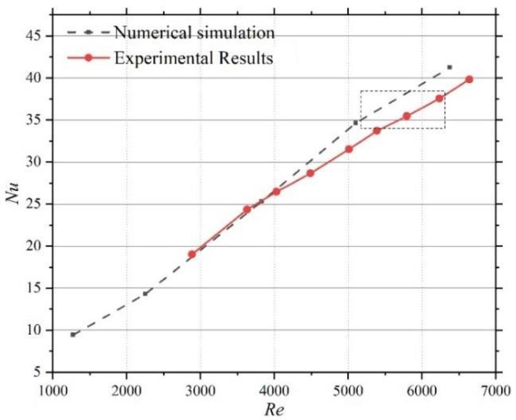
25] designed two arrangement modes in the horizontal and vertical directions for the experimental helium–water loop and found that a horizontal arrangement would lead to uneven distribution, thus resulting in differences from simulation results. Existing experimental studies focus on the thermal hydraulic characteristics of PCHEs and the construction of related heat transfer and pressure drop correlations. Limited by the small size and high pressure of PCHE channels, there are few experimental observation studies on the flow patterns in PCHE channels at present.
Based on the investigation and analysis of the literature, the research on S-CO
2 Brayton cycle power generation is still in the development stage. Studies on flow and heat transfer in PCHE belong to the field of applied research, and most of them focus on the establishment of the heat transfer correlation and the design of PCHEs [
26,
27,
28,
29]. Nevertheless, most studies are based on the assumption that the flow in the PCHE channel is evenly distributed, and few studies consider the uniformity of the flow distribution in each channel of the PCHE, PCHE pressure drops, and heat transfer efficiency, mainly because the flow channel is small. The internal flow parameters are difficult to measure. Thus, there are still problems in the study of PCHE heat transfer characteristics. For the straight barrel inlet header PCHE channel, the non-uniform flow distribution phenomenon is caused by the structure itself. If a guide plate is set up in the diversion area, then a higher flow can be obtained in the middle of the channel. Nevertheless, the additional guide plate structure is bound to cause a diversion area with increased pressure drop, leading to deterioration of the PCHE hydraulic characteristics on the whole, thus affecting the turbine inlet pressure in the Brayton cycle, which is a pyrrhic gain. In addition, due to the high operating pressure of the system, the setting of the guide plate may cause local stress concentration, which is not conducive to safe and stable operation of the system. Therefore, the design of the existing straight barrel inlet header PCHE must be optimized to improve the non-uniformity of the flow distribution in each layer of the PCHE so that the flow in the straight barrel inlet header PCHE can be generally evenly distributed.
This paper is aimed at the optimization structure of straight barrel inlet header PCHE. When S-CO2 flows in the PCHE, the structural types and working parameters of the inlet header and diversion zone may lead to differences in the flow distribution in each channel of the PCHE, and the uniformity of the flow distribution increases with increasing PCHE scale. This difference in flow distribution affects the thermal hydraulic characteristics of the PCHE and further reduces the comprehensive performance of the Brayton cycle power generation system. Therefore, a numerical simulation method is proposed to explore the influence of flow uniformity on the overall performance of the PCHE and improve the structure of the straight barrel inlet header PCHE to optimize the S-CO2 distribution in the PCHE flow channel.
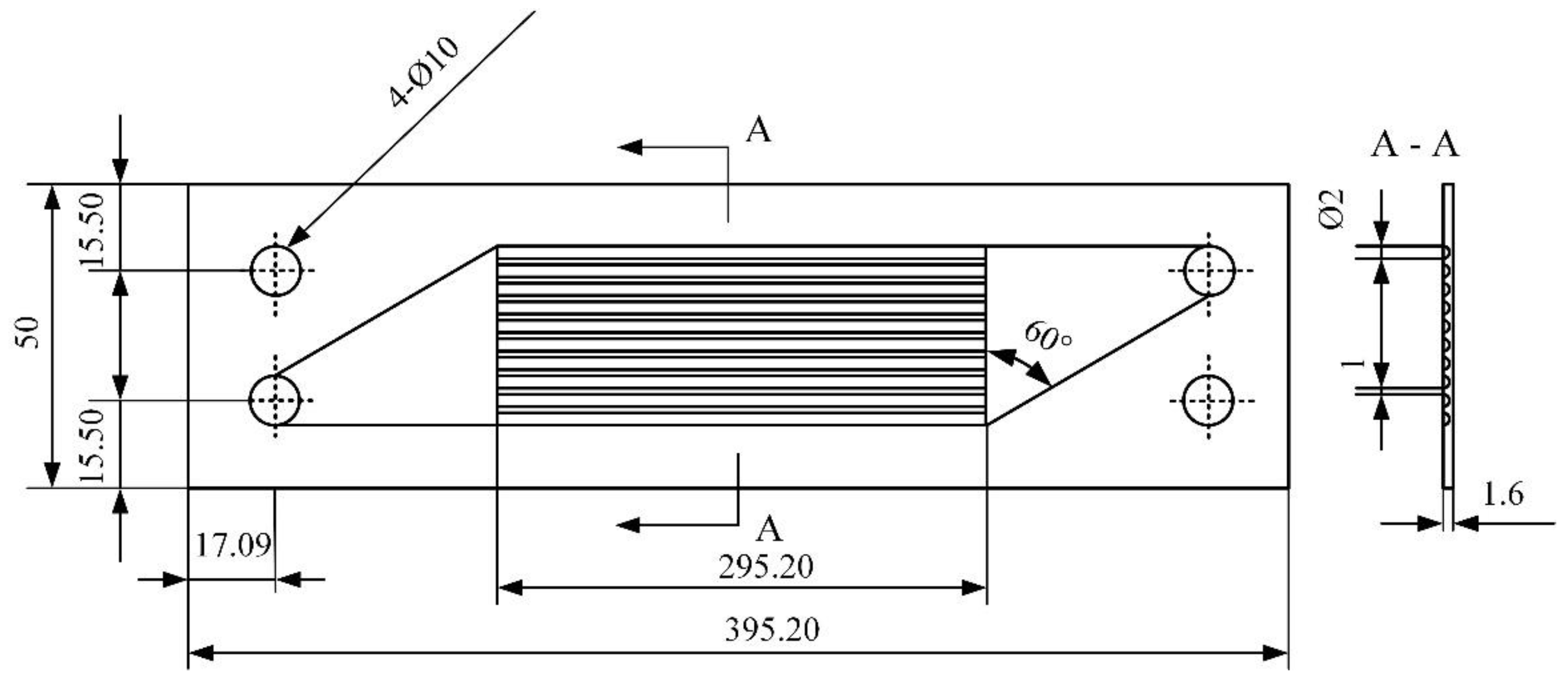
3. Flow Distribution Characteristics of the Tapered Header
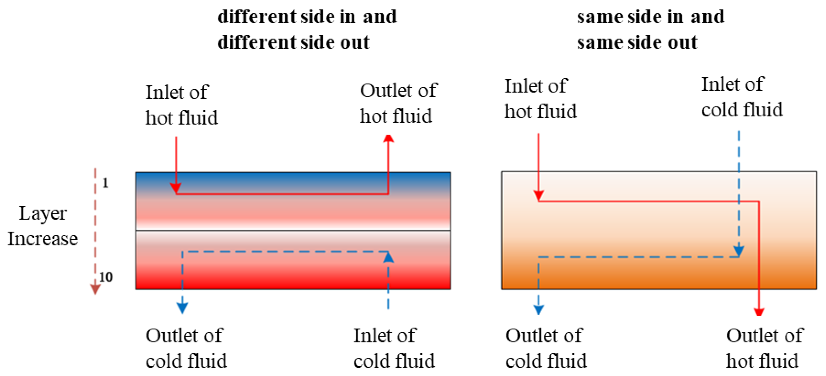
Under the condition of countercurrent heat transfer, there are two arrangement modes, as shown in
Figure 7. In the actual PCHE cold and hot side header arrangement, when the inlet headers of the cold and hot sides are on different sides and the outlet headers are also on different sides, this is simply referred to as “different side in and different side out”; when the cold and hot side inlet headers are on the same side and the outlet headers are also on the same side, this is termed “same side in and same side out”.
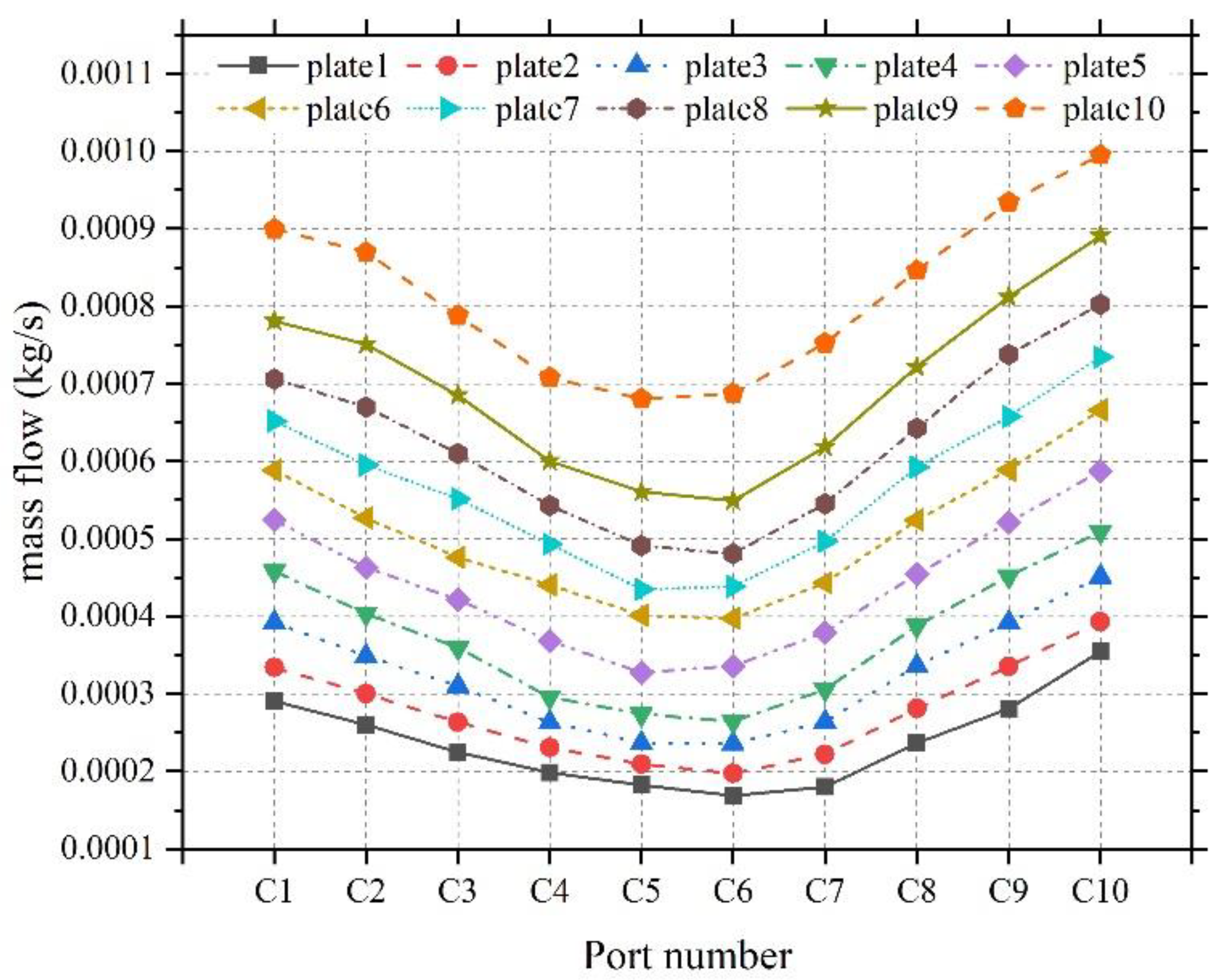
In this section, based on the simulation results, the flow distribution in the heat exchanger plate layer away from the entrance of the PCHE inlet header is found to be the highest, and that in the heat exchanger plate layer near the entrance of the PCHE inlet header is found to be the lowest. Under the different inlet and outlet configuration, the hot fluid has the highest flow distribution in the 10th heat exchanger plate layer, while in the first layer, the hot fluid has a minor flow distribution. The flow distribution of the cold fluid is the highest in the first heat exchanger plate layer. The flow distribution is the lowest in the 10th heat exchanger plate layer. For the same inlet and outlet configuration, the flow distribution of hot and cold fluids is the highest in the 10th heat exchanger plate layer, and the flow distribution is the lowest in the first heat exchanger plate layer.
For the “different side in and different side out” arrangement, the PCHE heat transfer unit in the first layer has less hot fluid flow and more cold fluid flow, which leads to a mismatch of the cold and hot side flows in the same heat transfer unit and excess cooling capacity of the cold fluid. However, in the PCHE heat transfer unit in the 10th layer, there is more hot fluid flow and less cold fluid flow, which leads to insufficient cooling capacity of the cold fluid, similar to the situation of dry burning in a boiler with less flow distribution for the high heat load. (Note: Heat transfer unit here refers to a cold-side heat exchanger plate layer and a hot-side heat exchanger layer plate constituting a cold and heat transfer unit layer.)
For the “same side in and same side out” arrangement, the flow distributions of both cold and hot fluids are small in the PCHE heat transfer unit in the first layer, while the flow distributions of both cold and hot fluids are enormous in the PCHE heat transfer unit in the 10th layer. Matching of cold and hot flows is adequately realized, and matching of the flows corresponds to matching of the heat loads, which can give full play to the cooling capacity of the cold fluid.
For the “same side in and same side out” arrangement, the flow rates and heat loads on the hot and cold sides match, but there is a significant asymmetry in the flow distribution from the first layer to the tenth layer. In the “different side in and different side out” arrangement, the flow rates and heat loads on the hot and cold sides are very different. Therefore, the uneven distribution of the flow rate must be improved to improve the comprehensive heat transfer performance of the PCHE.
According to the analysis results, the lower the layer number is, the more flow rate is distributed by the heat exchanger plate. Therefore, optimizing the configuration of the header into a tapered type can be considered so that when S-CO
2 flows downward in the tapered area, the pressure energy and velocity energy at the entrance of the heat exchanger plate in each layer from top to bottom remain unchanged. The backflow dead zone at the bottom of the header is eliminated to realize uniform distribution of the flow of the heat exchanger plate in each layer.
Figure 8 shows the structure diagram of the tapered header. The magnitude of different taper angles
θ represents the rate at which pressure energy is converted into velocity energy along the flow direction of the tapered area. Limited by the structural characteristics of the model, the diameter of the top circle is constant at
d1 = 10 mm, and the distance between the first heat exchanger plate and the tenth heat exchanger plate is 29.8 mm. Assuming that the bottom circle diameter
d2 is 0, the maximum value of the angle
θ is 18.55°; that is, angle
θ ranges from 0° to 18.55°. In this paper, 3° to 15° models which inlet mass flow is 0.05 kg/s are selected for numerical simulation to explore the influence of different structural parameters on the non-uniformity of the flow distribution in each layer. The
d2 corresponding to specific angles is listed in the following
Table 3.
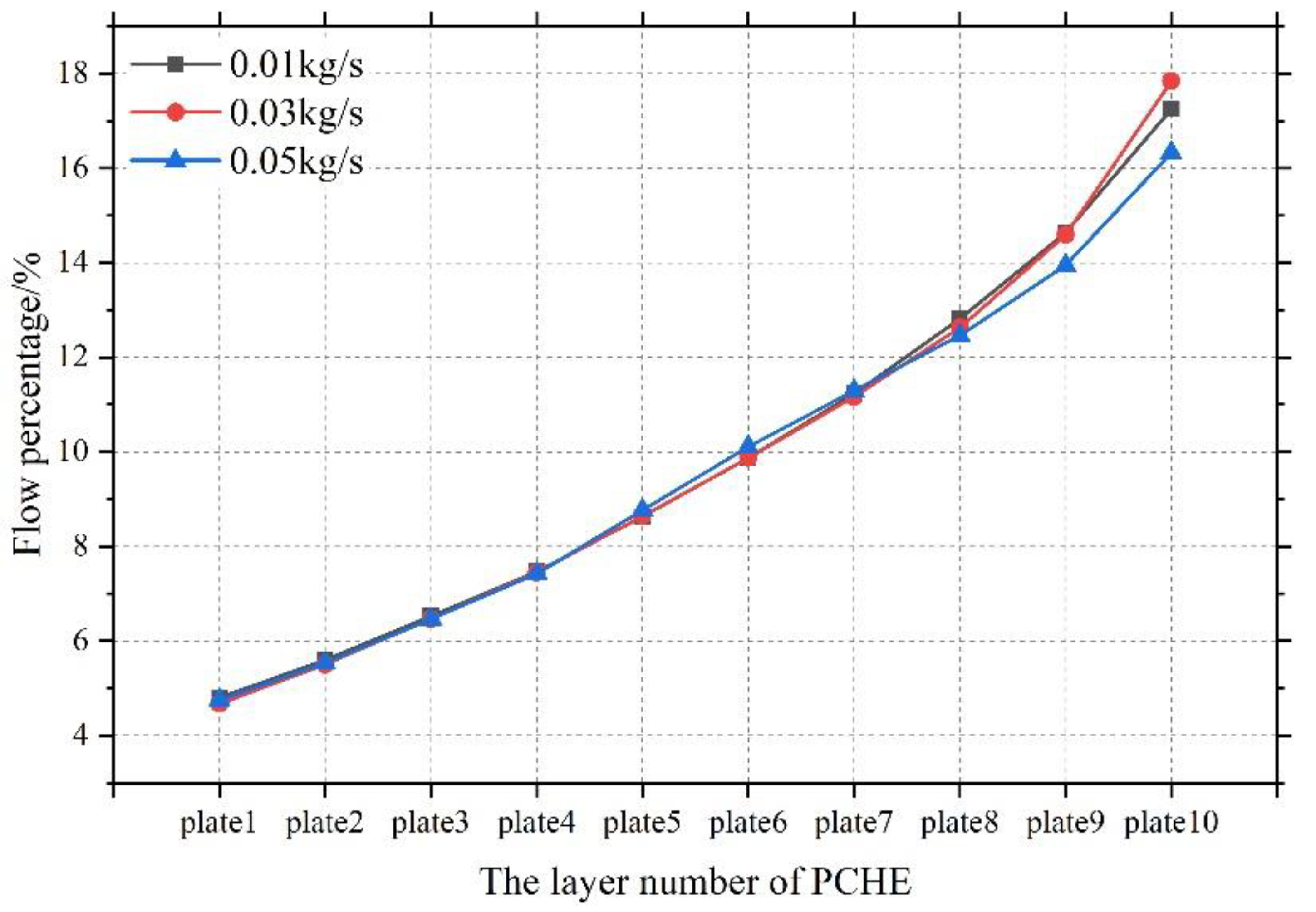
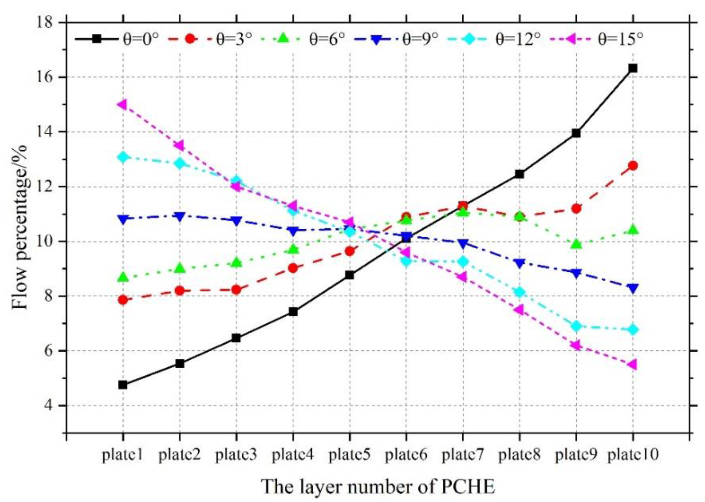
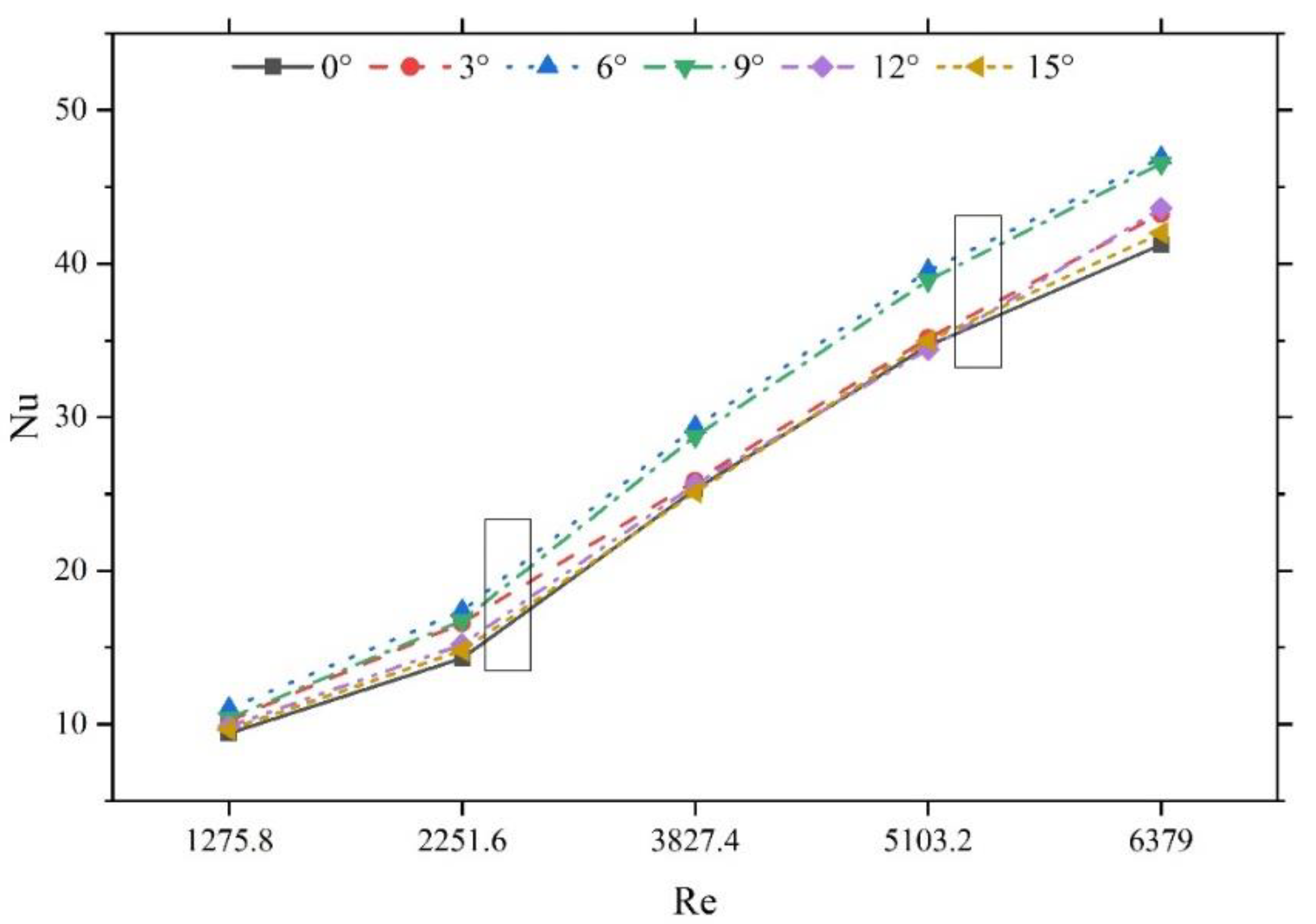
Figure 9 shows the proportion of the flow distribution in each layer of the models with different taper angles. The taper angle of the inlet header has a significant influence on the proportion of the flow distribution in each layer of the straight barrel inlet header PCHE. As mentioned above,
θ = 0° corresponds to the original configuration. The flow ratio gradually increases with the layer number. The deviation between the maximum and minimum values reaches 243%, significantly deviating from the state of uniform flow distribution in all layers. With the taper angle gradually increasing from 0, the flow distribution in each layer can be found to fundamentally follow a monotonic change law. In layer 1, the flow distribution of the heat exchanger plate gradually increases. In the 10th heat exchanger plate layer, the flow distribution decreases, and in layers 5 and 6, the flow distribution of the heat exchanger plate remains around 10%, the closest to a uniform flow distribution state. This occurs because as the taper angle
θ gradually increases, the diameter d
2 of the bottom circle of the header slowly decreases, and the inclination degree of the tapered header slowly increases, leading to a more significant proportion of pressure energy being converted to velocity energy along the flow direction of the header. The larger the velocity energy is, the less flow is distributed to the layer. Therefore, as the taper angle
θ increases, the average slope of the flow distribution ratio curve of each layer of the straight barrel inlet header PCHE gradually decreases from positive to 0 and then negative. On the whole, when
θ = 6° and
θ = 9°, the flow distribution in each layer is approximately 10%. Uniform flow distribution in each layer of the PCHE can be considered to be realized under these structural parameters.
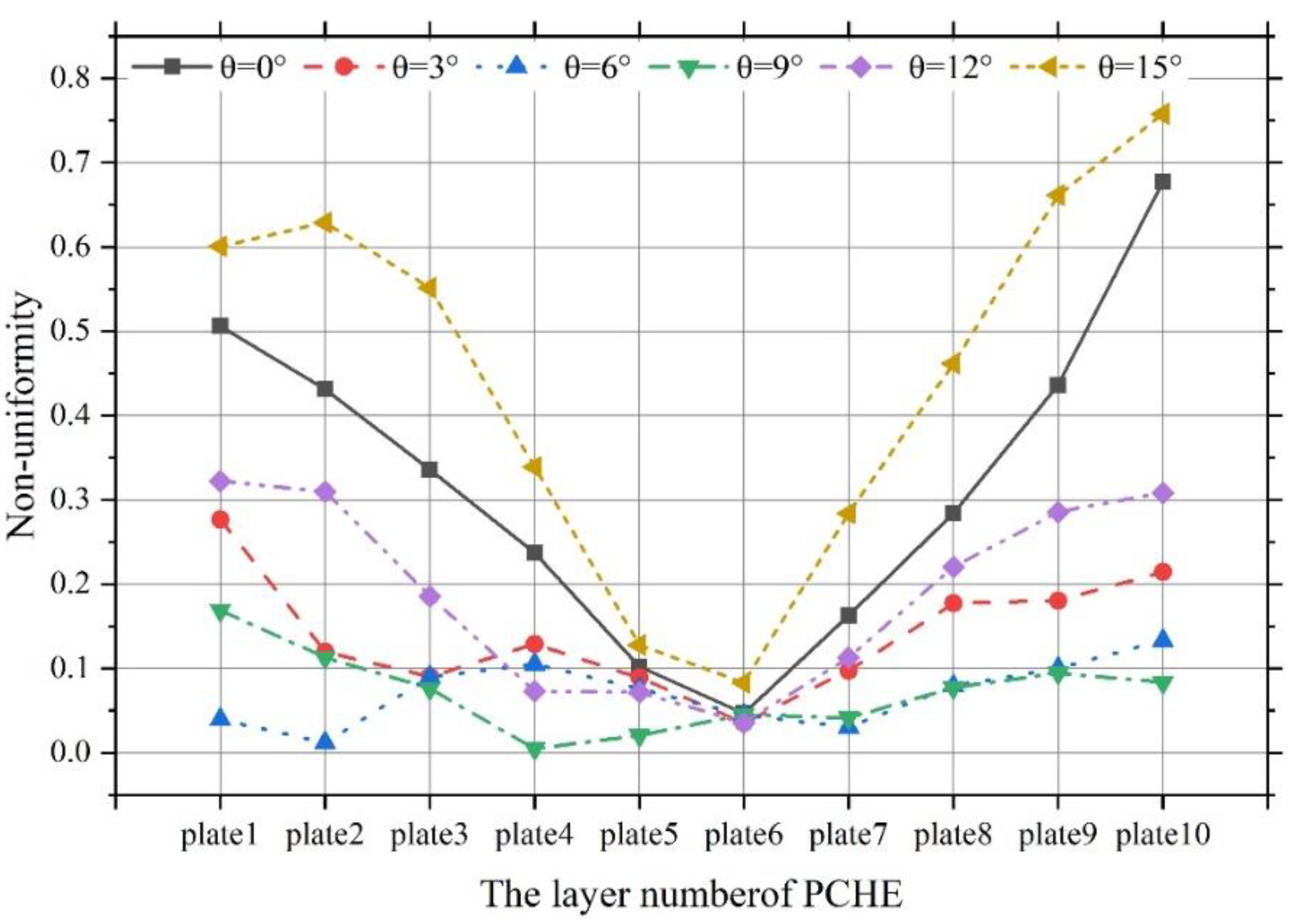
Figure 10 shows the non-uniformity of each layer of different taper angle models, and increasing the angle of the inlet header has a significant impact on the non-uniformity of the straight barrel inlet header PCHE. As previously mentioned,
θ = 0 corresponds to the original configuration, and the non-uniformity of the flow rate decreases with the gradual increase in the taper angle
θ when the taper angle
θ is 3–12° and the number of layers is 10. This indicates that the structure of the original configuration is optimized for the taper angle, which is advantageous for uniform distribution of the flow rate in the straight barrel inlet header PCHE to each heat exchanger plate layer. With an increase in the taper angle
θ, the results indicate that the optimum taper angle
θ can make the flow uniformly distribute to each layer in the straight barrel inlet header PCHE. When the taper angle
θ is 6° and 9°, the non-uniformity is less than 0.5, indicating that these two structural parameters of the header can significantly reduce the non-uniformity of the internal flow distribution of the straight barrel inlet header PCHE and realize uniform flow rate in each heat exchanger plate layer. When the taper angle
θ is increased to 12° and 15°, compared to 6° and 9°, it is not conducive to uniform distribution in each heat exchanger plate layer of the straight barrel inlet header PCHE. The distribution results indicate that to achieve uniform distribution in each heat exchanger plate layer, the taper angle
θ of the inlet header should be taken to be between 6° and 9°.
For taper angles
θ from 0° to 15°,
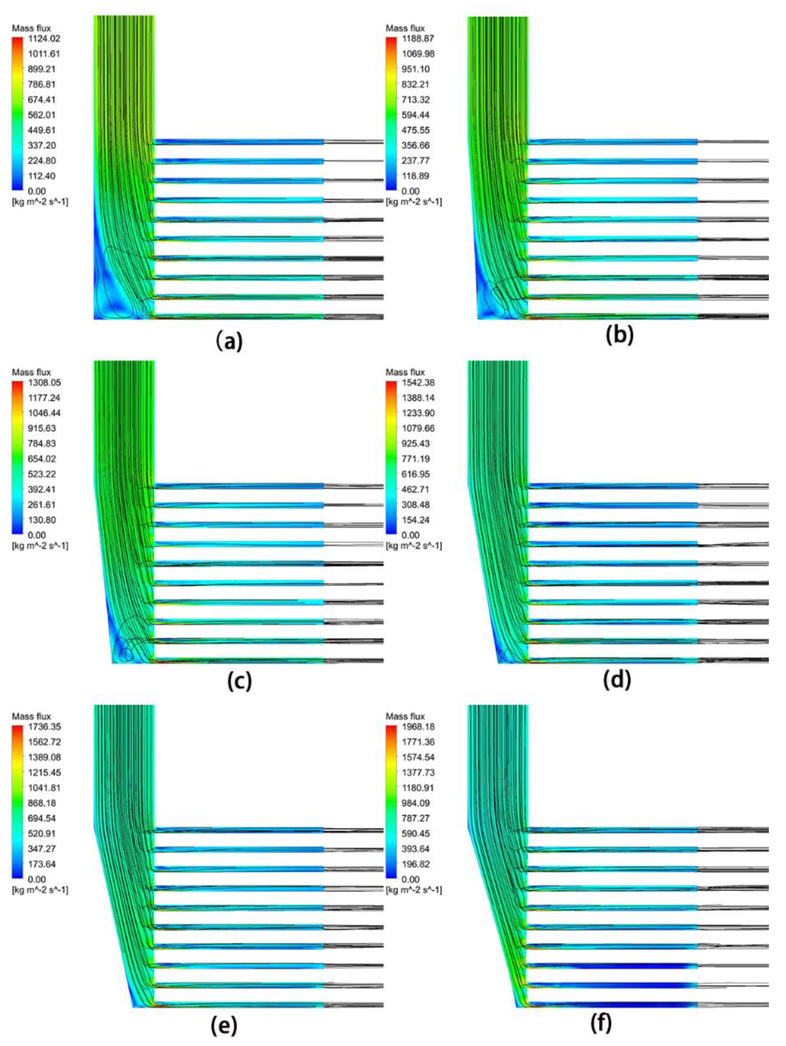
Figure 11 shows the mass flow rate flow diagram and mass flow rate cloud diagram, which reflect the velocity distribution in the inlet header and each heat exchanger plate layer, and fluid streamlines showing the flow field can be observed. The existence of a backflow area can be found, and analysis of the content indicates that with increasing taper angle, the backflow dead zone decreases. When
θ = 12°, the backflow dead zone disappears completely. The maximum local value of the mass flow rate tends to appear on the heat exchanger plate near the lower part of the header. With increasing taper angle, the red area at the entrance of the bottom heat exchanger plate gradually becomes smaller, indicating that the pointed tip of the tapered header can regulate the flow distribution ratio in each heat exchanger plate layer.
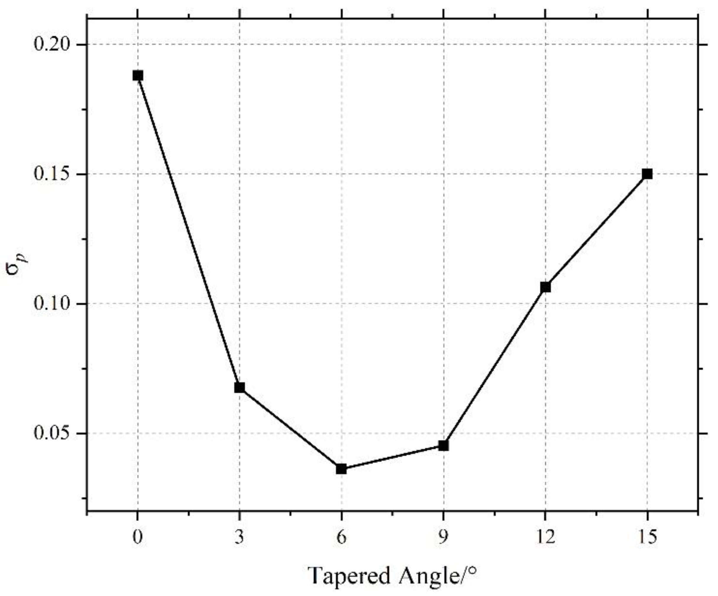
Figure 12 shows the statistical results of the standard deviation (
) of the non-uniformity of each layer. According to the analysis of the trend in the figure of
, when the taper angle
θ is 3–15°,
is less than that when the taper angle
θ is 0°, which indicates that optimization of the original configuration of the inlet header into a tapered header is conducive to evenly distributing the flow in the straight barrel inlet header PCHE to each heat exchanger plate layer.
first decreases and then increases with decreasing angle
θ, indicating an optimal taper angle
θ for evenly distributing the flow in the straight barrel inlet header PCHE among all the layers. When the taper angle
θ is 6° and 9°,
is less than 0.05, indicating that the header with these two structural parameters can significantly reduce the non-uniformity of the flow distribution in the straight barrel inlet header PCHE and realize uniform flow distribution in each heat exchanger plate layer. When the taper angle
θ increases to 12° and 15°,
is greater than the corresponding value when the taper angle is 6° and 9°, which is not conducive to uniform distribution of the flow rate in each heat exchanger plate layer in the straight barrel inlet header PCHE. The distribution results show that to realize uniform flow distribution in each heat exchanger plate layer, the inlet header taper angle
θ should be between 6° and 9°.
5. Conclusions
In this work, we studied the flow distribution characteristics of the straight barrel inlet header PCHE by a numerical simulation method. We analyzed the flow mechanism of the extremely uneven flow distribution in each layer.
In a single flow channel, the non-uniform flow distribution phenomenon in the heat exchanger plate layers is caused by the structure itself. If a guide plate is set up in the diversion area, then a higher flow can be obtained in the middle of the channel. Nevertheless, the additional guide plate structure is bound to cause a diversion area with increased pressure drop, leading to the deterioration of the PCHE hydraulic characteristics on the whole, thus affecting the turbine inlet pressure in the Brayton cycle, which is a pyrrhic gain. In addition, due to the high operating pressure of the system, the setting of the guide plate may cause local stress concentration, which is not conducive to the safe and stable operation of the system. Therefore, the design of the existing straight barrel inlet header PCHE must be optimized to improve the non-uniformity of the flow distribution in each layer of the PCHE so that the flow in the straight barrel inlet header PCHE can be approximately evenly distributed and the system can run under conditions close to the design point.
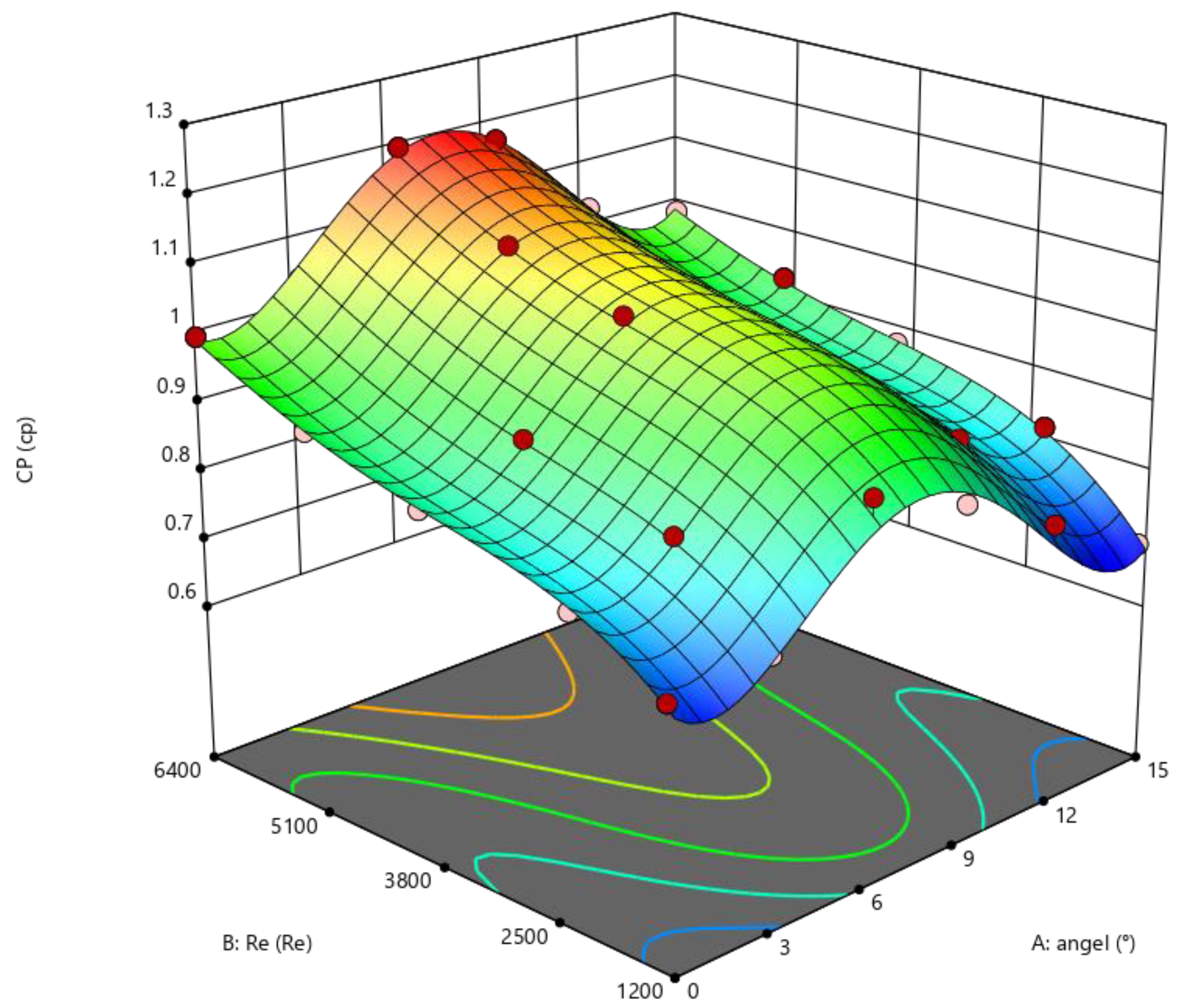
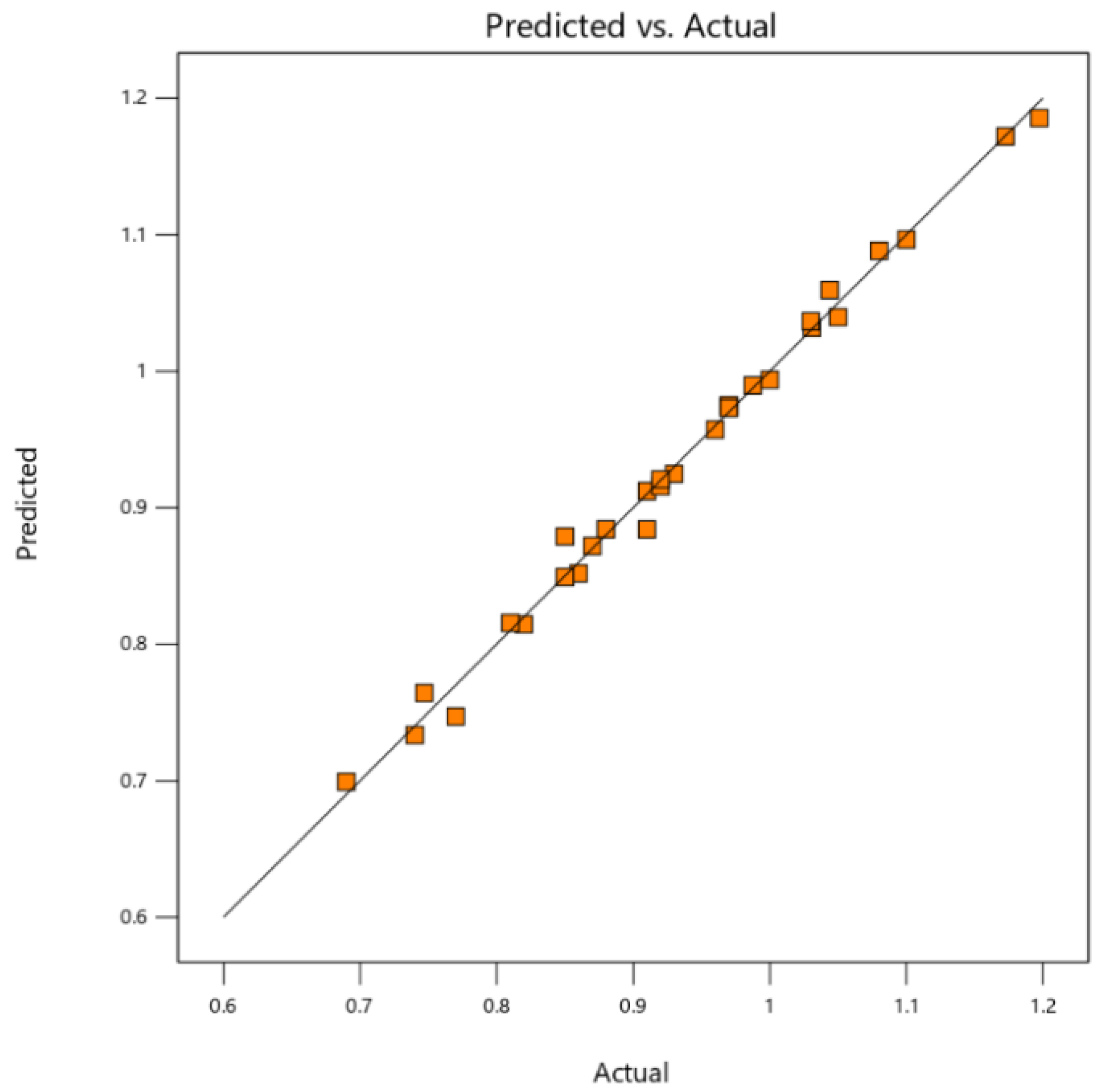
The problem of flow matching on the cold and hot sides was analyzed according to two different layout modes of “different in and different out” and “same in and same out”. Then, the inlet header was optimized as a tapered type to find the best range of taper angles and analyze the influence of different taper angles on the thermal hydraulic characteristics of the straight barrel inlet header PCHE. The results show that when the taper angle varies from 6° to 9°, the standard deviation of the non-uniformity of the flow distribution in each layer of the straight barrel inlet header PCHE is less than 0.05, and the flow distribution in each layer is relatively uniform. The comprehensive heat transfer performance of the straight barrel inlet header PCHE can be improved by 17.3–19.7%. Finally, the response surface and a genetic algorithm were combined to optimize the inlet header. Compared with the standard structure, the heat transfer performance of the optimized system was improved by 19.7%, reaching 1.187. This study can provide theoretical guidance for the design of the PCHE inlet header.


