Article

Towards Trust Hardware Deployment of Edge Computing: Mitigation of Hardware Trojans Based on Evolvable Hardware

School of Computer Science and Technology, Xidian University, Xi’an 710071, China
*
Author to whom correspondence should be addressed.
Appl. Sci. 2022, 12(13), 6601; https://doi.org/10.3390/app12136601
Submission received: 1 June 2022 / Revised: 23 June 2022 / Accepted: 25 June 2022 / Published: 29 June 2022

Abstract

:
Hardware Trojans (HTs) are malicious hardware components designed to leak confidential information or cause the chip/circuit on which they are integrated to malfunction during operation. When we deploy such hardware platforms for edge computing, FPGA-based implementations of Coarse-Grained Reconfigurable Array (CGRA) are also currently falling victim to HT insertion. However, for CGRA, an evolvable hardware (EHW) platform, which has the ability to dynamically change its configuration and behavioral characteristics based on inputs from the environment, provides us with a new way to mitigate HT attacks. In this regard, we investigate the feasibility of using EHW to mitigate HTs that disrupt normal functionality in CGRA in this paper. When it is determined that HT is inserted into certain processing elements (PEs), the array autonomously reconfigures the circuit structure based on an evolutionary algorithm (EA) to avoid the use of HT-infected (HT-I) PEs. We show that the proposed approach is applicable to: (1) hardware platforms that support coarse-grained reconfiguration; and (2) pure combinatorial circuits. In a simulation environment built in Python, this paper reports experimental results for two target evolutionary circuits and outlines the effectiveness of the proposed method.

1. Introduction

Current edge computing systems are deployed in highly complex intelligent application scenarios with dynamically changing requirements. In order to provide the expected performance in these situations, the use of flexible hardware/software platforms at the edge has become widespread. However, due to a lack of resilience to untrusted entities, these flexible hardware platforms are vulnerable to various threats and attacks. To date, several steps of integrated circuits (ICs) development are outsourced to direct or indirect collaboration between different (sometimes untrusted) parties [1], which has opened the door to manipulation of ICs. The globalization process has created new sources of attack. Untrusted entities can disrupt any point of this IC supply chain in a variety of ways, with hardware Trojans (HTs) being the most dangerous due to their stealthy nature [2]. HTs are defined as malicious building blocks that are inserted into ICs to cause undesirable behavior [3]. When HT is activated in some way, it can lead to leakage of sensitive information, changes in circuit functionality, increased power consumption, and even physical permanent damage.
To ensure the safety and reliability of ICs, we must first make sure whether the HT circuits exist. Hence, there are a large number of studies focusing on detecting HTs in ICs. To date, The methods for detecting HT fall into two main categories: (1) dynamic detection; and (2) static detection. The dynamic detection method is designed to detect HT circuits inserted by untrusted foundries during the manufacturing process [4,5,6,7,8,9]. The static detection methods use testability-based structural features extracted from IC design files to match HTs’ features [10,11,12,13,14]. However, since attackers may create special types/hard-to-activate HTs, there is no complete guarantee that HT circuits can be identified during the detection phase. Once the HTs are activated at runtime, it is common practice to replace the existing HT-infected (HT-I) device. However, in complex and dangerous edge computing applications, manual replacement/repair of hardware devices is almost impossible. As the ideas of artificial intelligence have been incorporated into security and high trust research, evolvable hardware (EHW) is becoming an important approach for fault-tolerant and highly reliable designs [15]. Among them, Virtual Reconfigurable Circuits (VRC) and Coarse-Grained Reconfigurable Array (CGRA) are popular ways to implement EHW architectures that reconfigure the circuit structure in one or a few clock cycles [16]. This offers the possibility to mitigate HT attacks on EHW architectures. However, relevant research in this area is still in the exploratory stage.
In this paper, we investigate a solution for HT mitigation using EHW on CGRA. Specifically, by using an evolutionary algorithm (EA) to explore and generate new circuit structures that no longer use the PEs infected by HTs. Meanwhile, The new circuit structure must also satisfy resource constraints, namely, minimize the resource overhead. In addition, the process of EA exploration is time-consuming, which is undesirable for most electronic systems. To address this, we optimize the evolvable region (ER) to accelerate the convergence. In summary, we make the following novel contributions:
  • It is the first time employing an EA-based mitigation method against HTs attack in PE of CGRA;
  • A method to optimize the evolvable region is proposed for reducing the evolution time;
  • The experimental results show the effectiveness of the proposed scheme for mitigating HT attacks and confirm that optimizing the evolvable region can accelerate the evolution efficiency at the edge.
The paper is structured as follows. Section 2 provides information on HTs in digital circuits, evolutionary algorithms and evolvable hardware. In Section 3, we describe the proposed HT mitigation method. In Section 4, we evaluate the effectiveness of our approach based on two target circuits. Section 5 concludes the paper.

2. Preliminaries

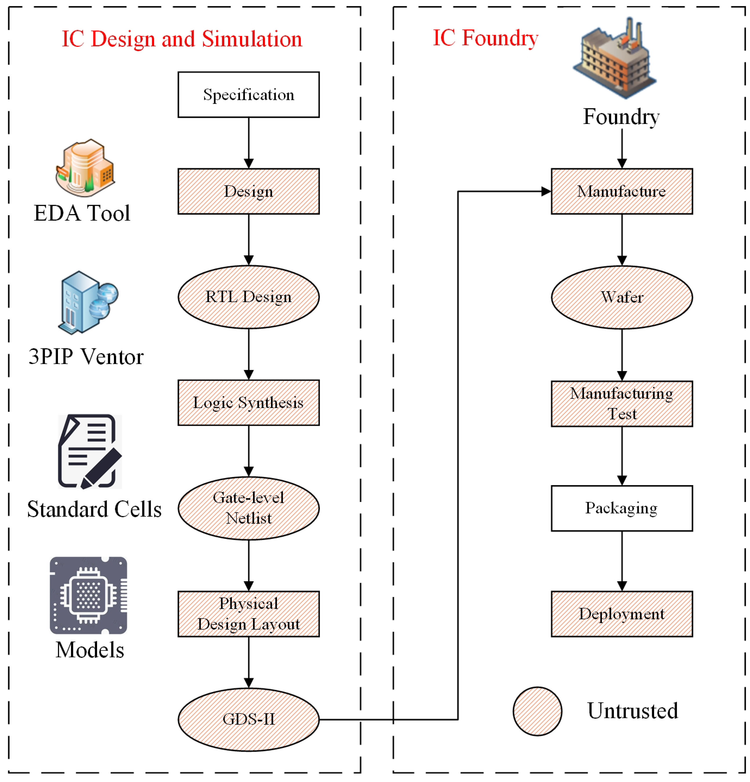
2.1. Hardware Trojans

HTs are malicious circuits designed to alter the original chip/circuit functionality, leak secret information, or even cause the permanent failure of the chip on which they are integrated at runtime. As shown in Figure 1, HTs can be inserted by untrusted foundries and third-party IP core vendors at different stages of FPGA and ASIC (Application Specific Integrated Circuit) design development and manufacturing. HTs consists of two parts: a trigger and a payload. The trigger usually corresponds to a rare data input (sequence), while the payload is the activity that causes a data leak or fault when the HT is triggered. For example, in communication systems, a chip infected with HT can leak sensitive data to the outside world when a specific combination or sequence of input signals is transmitted [17].
To prevent/alleviate the damage of the HTs to the circuit, we must first make sure whether the HTs exist in ICs. Hence, there are a large number of studies focusing on detecting HTs in ICs. The methods for detecting HT fall into two main categories: (1) dynamic detection; and (2) static detection. The dynamic detection method is designed to detect HT circuits inserted by untrusted foundries during the manufacturing process [4,5,6,7,8,9]. The static detection methods use testability-based structural features extracted from IC design files to match HTs’ features [10,11,12,13,14]. Since attackers may create special types/hard-to-activate HTs, there is no complete guarantee that HT circuits can be identified during the detection phase. Once the HTs are activated at runtime, it is common practice to replace the device infected with HT. However, in complex and dangerous applications, manual replacement/repair of hardware devices is almost impossible. Therefore, it is necessary to adopt intelligent mitigation mechanisms to deal with HT attacks in the ICs.
To date, intelligent mitigation mechanisms aiming at HT attacks are only available for programmable devices or virtual reconfigurable architectures. The circuit infected by HTs can be changed by reconfiguration to eliminate HTs. However, relevant research in this area is still in the exploratory stage. Labafniya, M et al. proposed a mechanism to mitigate HT for VRC implemented on field-programmable gate arrays (FPGAs) [18]. The circuits are autonomously and periodically reconfigured to eliminate the impact of HT on the circuit. Liu, L et al. proposed a security mapping approach, dynamic resource management based on security values, to enhance CGRA against HTs by selectively protecting PEs [19]. However, this approach is based on a triple modular redundancy architecture to mitigate HTs, which has a high resource overhead and is difficult to mitigate in the presence of multiple HTs. In this paper, an EA-based HT mitigation mechanism is proposed exploratively on CGRA. HT attack mitigation is achieved by reconfiguring the circuit to avoid the use of HT-I PEs.

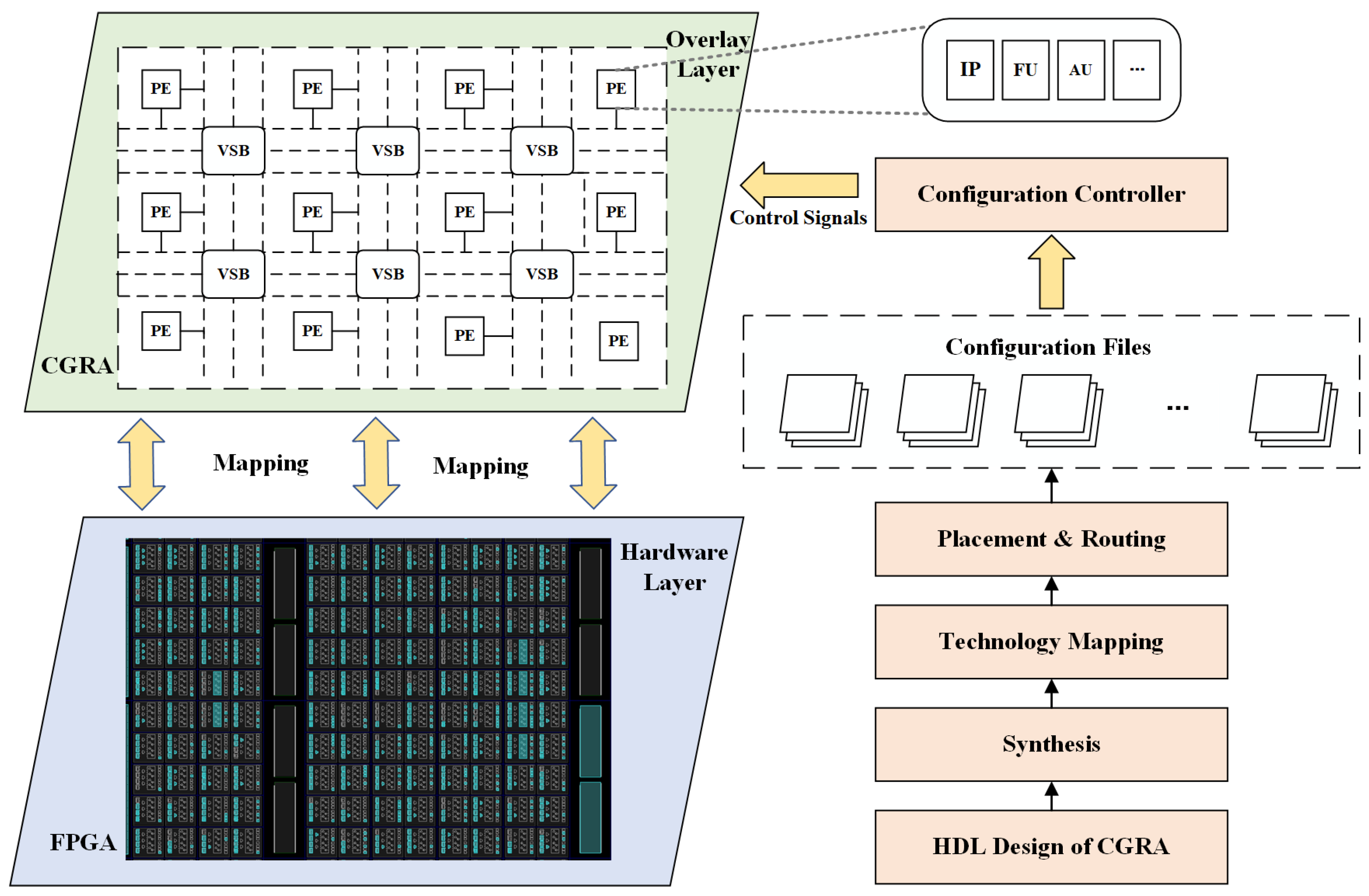
2.2. Coarse-Grained Reconfigurable Array

FPGAs have proven their potential for accelerating High-Performance Computing (HPC) applications. Traditionally, such a device primarily contains fine-grained elements, such as look-up tables (LUTs), switch blocks (SBs), and connection blocks (CBs), as the basic programmable logic blocks. However, traditional implementations suffer from high reconfiguration and development costs [20]. To solve the above problems, programmable logic components are defined at a higher level of abstraction. These components are called Processing Elements (PEs) and the group of PEs along with the inter-connection network form an architecture called CGRA [21]. This abstraction facilitates faster reconfiguration/replacement of applications.
The CGRA introduced in this paper is shown in Figure 2. It consists of reconfigurable PEs which are connected to each other using reconfigurable Virtual Switch Blocks (VSBs). In the CGRA tool flow (right-hand side of Figure 2), the user will determine the CGRA settings that will configure the required configurable components of the CGRA to realize the desired application [22,23]. In CGRA, PE is the main unit that executes the application and can be configured by IP cores, Functional Units (FU) or Arithmetic Units (AU) with different granularities. It occupies most of the entire CGRA area and is the easiest target for HTs. At the same time, its redundancy and reconfigurability characteristics make it difficult to detect HTs. Therefore, it is very necessary to implement a hardware Trojan mitigation mechanism in PEs.

2.3. Evolutionary Algorithms and Evolvable Hardware

Evolutionary algorithms (EA) are population-based metaheuristic optimization techniques inspired by biological evolution [24]. Currently, EAs are successfully applied in different fields such as arithmetic circuit design [25], the design of fault-tolerant systems [26], and power consumption optimization [27]. Genetic algorithm (GA) is one of the more widely used EAs and has been successfully applied in various digital circuit implementations [28,29]. In [30], parallel GA is used to design digital circuits based on FPGA architecture. The employed GA involves the use of a linear representation that can be easily used to evolve the system. In [25], the logic circuits are organized on a two-dimensional array of cells, and the use of GA has the best circuit design in terms of circuit complexity, power, and time delay. Given the ease of implementing circuit design in GA, we use GA as an EA in this paper.
EA is essentially an optimization technique. The candidate solutions to the optimization problem are individuals in the population, and the fitness function determines the quality of the solution. Depending on how the fitness is evaluated, evolutionary hardware can be divided into two categories: extrinsic evolution and intrinsic evolution. In extrinsic evolution, the EA is implemented on an external computing device, and the fitness of all chromosomes is evaluated by software models and simulators. Only the best option is reconfigured on the hardware device to the desired circuit. In intrinsic evolution, the EA is implemented on the external computing device, but the evaluation of each chromosome is performed on the programmable device by reconfiguration [31]. Compared to extrinsic evolution, the implementation of intrinsic evolution is more complex and time-consuming.

3. Proposed HT Mitigation Method

3.1. Overview

In this paper, a new approach to protect FPGA-based implementations of CGRA from HTs attacks is proposed. CGRA consists of a large number of PEs, and the units can communicate with each other over an on-chip network. PEs are the basic units that implement the functions of the circuit, and are the most vulnerable parts to HTs infection. In this paper, we only focus on the situation where HT is inserted into the PEs of the CGRA. For this, we employ EA to search for a new circuit structure that does not contain PEs inserted by HTs.
Figure 3 shows our proposed architecture for protecting CGRA from HTs attacks using circuit evolution. There are two important parts: the optimization of the evolvable region and the evolution algorithm. The number of PEs is chosen according to the functionality of the circuit implementation. If the circuit is complex and/or large, the EA module will evolve over a large number of PEs, so the evolution process can be very time-consuming. In order to improve the evolution efficiency, we optimize the evolvable region based on the original circuit structure. The evolutionary algorithm is the core of the entire circuit evolution process, which traverses the optimal circuit structure based on the evolvable input regions and the evolutionary goals of the circuit, and must also satisfy the corresponding constraints. In addition, we use a validator to input test vectors in the offline stage to check the function of the PE in CGRA to determine whether the PE is infected by the HTs and input the location information of HTs to the module of optimization of the evolvable region and EA. After the EA module evolves to obtain the optimal circuit structure, a configurator is used to load the circuit configuration file onto the CGRA to reconfigure the PE to protect the circuit from HTs attacks.

3.2. Optimization of Evolvable Regions

EA is usually time-consuming for generating optimal target circuit structures, especially when the circuits are complex and/or oversized. To reduce the evolution time, we propose an algorithm to optimize the evolvable region. While retaining the original circuit occupying the on-chip region, the evolvable region is expanded step by step until it stops when the number of redundant PEs in the current region is satisfied to be greater than HT-I PEs. Figure 4 shows the method and the effect of optimizing the evolvable region.
Algorithm 1 describes the pseudo-code for optimizing the evolvable region. The algorithm’s input is all PEs on the CGRA architecture, and the output is the optimized evolvable region. First, we assign coordinate values to the positions of all PEs with the purpose of quantifying the distance and area (lines 2–4). Based on this, we traverse to find the coordinates of the leftmost, topmost, rightmost and bottommost ( X l , Y t , X r , Y b ) PEs of the current circuit to be evolved (lines 6–8). Once these four coordinates are obtained, the area of the rectangle in which the circuit to be evolved is located is calculated (line 10). If the number of free PEs ( F p ) contained in this rectangular area is greater than the number of PEs inserted by the HTs ( H p ), then this area is the evolvable area. Otherwise, the clustering solves for the center coordinates ( C P ) of the circuit to be evolved (line 17). Afterward, an attempt is made to expand the original region with rectangular cells (line 19) and calculate the Euclidean distance (lines 21–23) of all the newly added PEs from the CP. After that, the Euclidean distances are sorted in ascending order (line 25), and the relationship between the number of F p and the number of H p in the current region is compared in order (lines 27–29). If there are joined rectangular regions in which F p is greater than H p , the current region is an evolvable region; otherwise, lines 18–31 are repeated until the PE requirement for evolution is satisfied. The time complexity of this algorithm is O(n).
Algorithm 1 Optimization of Evolvable Region Algorithm
Input:All PEs on the CGRA
Output:Optimized Evolvable Region ( O E R );
List_PEs:all PEs; ListC_PEs:PEs used in the current evolutionary circuit.
1:
/* Assign the position of all PEs ( P E _ p o s ) to coordinate values ( c v ) */
2:
foriin l e n g t h ( L i s t _ P E s ) : do
3:
   Assign P E _ p o s i c v i
4:
end for
5:
/* Traverse to find the X l , Y t , X r , Y b in the current evolutionary circuit */
6:
foriin l e n g t h ( L i s t _ P E s ) : do
7:
   Find( X l , Y t , X r , Y b )
8:
end for
9:
/* Calculate the initial area ( I r a ) occupied by the current evolutionary circuit */
10:
       I r a = ( X l X r ) × ( Y t Y b )
11:
/* Compare the number of free-PEs ( F p ) in the Ira with the number of HT-I PEs ( H p ) */
12:
if   F p > = H P   then
13:
   Output  I r a O r a
14:
   break
15:
else
16:
   /* Clustering to solve the center point ( C P ) of the current evolutionary circuit */
17:
    C P C l u s t e r i n g ( L i s t C _ P E s . c v )
18:
   /* Expand the evolution area ( e r a ) horizontally or vertically
19:
    L i s t _ E r a E x p e n d ( I r a )
20:
   /* Calculate Euclidean_distance between the added coordinates ( a _ c v ) and C P in turn */
21:
   for i in l e n g t h ( L i s t _ E r a ) : do
22:
      E u c l i d e a n _ d i s t a n c e i C a l c u l a t e ( C P , a _ c v )
23:
   end for
24:
   /* Sort the Euclidean distance in ascending order */
25:
    L i s t S _ E r a S o r t ( E u c l i d e a n _ d i s t a n c e ) ;
26:
   /* Compare sequentially in ascending order of Euclidean distance Fp and Hp */
27:
   if  L i s t S _ E r a . F p > = H P  then
28:
     Output  L i s t S _ E r a O r a
29:
     break
30:
   else
31:
     repeat (18)–(31);
32:
   end if
33:
end if

3.3. Evolutionary Algorithm

The overall implementation of the evolutionary algorithm is shown in Figure 5. We use external evolution to search for the optimal circuit structure and deploy the optimal circuit structure that satisfies the conditions to CGRA for implementation. We use one-dimensional genetic coding to characterize individuals, where the coding length is related to the specific circuit structure, reflecting the mapping of each function in the circuit to the PE. At first, we generate an initial population, where each individual in the population represents a circuit structure, and then set up an evaluation function to evaluate the individuals to further select the best ones for subsequent evolution. For traversing the optimization space, we employ crossover and mutation to generate new (better) individuals.
The evolutionary process is defined as a search for the optimal circuit structure Copt that minimizes the value of the evaluation function, and the evaluation function is set as:
E v a l u t i o n _ v a l u e i = i = 1 n W i r e _ l e n g h t i + Cos t i .
In Equation (1), Wire_length represents the span between selected adjacent PEs and its sum is used to measure the overall circuit wiring length, representing the resource consumption and overall timing of the circuit. Cost represents the feasibility limit, w.r.t., a PE in CGRA cannot perform two functions at the same time and the PE inserted by HTs can no longer be used. It is expressed as:
Cos t i = 10000 , i f p o s m = p o s n ( p o s m , p o s n C ) 10000 , i f p o s i = p o s H T - I ( p o s i C ) 10000 , i f p o s i i s u s e d b y o t h e r c i r c u i t s ( p o s i C ) 0 , o t h e r w i s e
where C represents the generated circuit structure and pos represents the location of the PE. EA-based evolution involves traversing the design space by generating new (and better) individuals for each offspring. We use the following operations to generate new individuals for the next generation population.
Selection: We used a tournament selection method to select individuals for the next generation. This selection method involves selecting the most suitable individuals, 20 (in this paper) individuals from the current population for the next generation.
Crossover: We use the following operation to achieve crossover between two individuals of a generation—selecting a fragment of the first half of the first individual to cross with a fragment of the second half of the second individual to generate a new individual in exchange.
Mutation: The mutation is essential to prevent the search from getting stuck in some local optimum. We use single-point mutation to randomly select available PEs, setting a 20% probability of randomly selecting a point of the current individual for single-point mutation.

4. Evaluation Results

This section describes the details of the scheme proposed in this paper through the implementation of two example circuits. These two circuits perform arithmetic operations. They occupy different numbers of PEs and perform evolution on CGRAs with different resources. Based on the above example circuits, we have investigated the use of the proposed approach against HT protection.

4.1. The Target Circuit and the Expected Behavior of the HT Mitigation Mechanism

Example circuit-I performs ((a + b) × c − d)/e arithmetic operations, occupying four PEs, and is deployed on a CGRA with a total of nine PEs. Example circuit-II performs (a)(a + b) × (c + d) − m/(e + f) × (g + h) arithmetic operations, occupies nine PEs, and is deployed on a CGRA with 25 PEs. The data flow diagrams (DFG) of the two circuits are shown in Figure 6.
Examples of circuits infected by HT and corrected by CGRA reconfiguration are shown in Figure 7 and Figure 8, where the blue arrows represent the data flow. Figure 7a and Figure 8a show the initial version of the circuit, and Figure 7b and Figure 8b show the infected version of the circuit with one PE infected with HT in circuit-I and two PEs infected with HT in circuit-II. After performing the EA and reconfiguring the CGRA, the expected circuit function is corrected as shown in Figure 7c,d and Figure 8c,d.

4.2. Experimental Results

The experiments are conducted by external evolution on a PC with a 4-core processor of 11th Gen Intel(R) Core(TM) i5-1130G7 with 1.1 GHz and 8 GB of memory. Since the scale of the experimental circuit is small, the population size is set to 100, and the corresponding iterations are set for circuit-I and circuit-II, respectively 2000 and 20,000 iterations.
We count the time required to achieve EA in different ERs to evaluate the impact of ER on evolutionary efficiency. Meanwhile, the evolution success rate (ESR) is also proposed as a metric to assess the impact of the insertion of different numbers of HTs in CGRAs on evolution. The ESR is defined as: the number of successful evolutions/the total number of evolutions × 100%, and the total number of evolutions is set to 10 in this paper. The corresponding number of iterations are evolved for circuit-I and circuit-II, where the optimal evolution results are shown in Figure 9.
Table 1 and Table 2 show the time required to implement EA in different ERs for circuit-I and circuit-II. Circuit-I requires four PEs to implement EA in all evolvable region (AER, 9PE) and in the optimized evolvable region (OER, 6PE), respectively, and it can be seen that the evolution time required in the OER is less than the AER. The increase in evolution efficiency is not very significant, mainly due to the simpler implementation of circuit-I and the small of AERs. Circuit-II requires eight PEs to implement EA in the AER (25PE) and in the OER (20PE, 16PE, 15PE, 12PE, 10PE), respectively. It is clear from Table 2 that the evolution efficiency increases sharply as the ER is reduced. The above experiments fully illustrate that shrinking ER can help improve the evolution efficiency. The reason is that optimizing ER can reduce the search space to accelerate the evolution of individuals toward the optimal solution. In particular, when the ER is similar to the circuit size, only a few of the generated initial individuals satisfy the solution conditions and it is not easy to expand the search range, so the convergence is accelerated in the subsequent iterations.
Figure 10 shows the effect of the insertion of different numbers of HTs in the CGRA on the ESR. Circuit-I requires four PEs to achieve the function and it evolves on a CGRA with nine PEs. In Figure 9a, it can be seen that circuit-I evolves successfully as long as there are more than four available PEs in the CGRA. Circuit-II requires eight PEs to achieve functionality and it evolves on a CGRA with 25 PEs. The range of the number of insertion HTs at this point is 1–25. Since the ESR is 100% for all insertions less than 10 and 0 for all insertions greater than 20, only this representative part is shown in Figure 9b to illustrate the variety of ESR with the number of insertion HTs. When the number of insertion HTs reaches 15, there are only 10 PEs available in CGRA. At this time, the ESR cannot reach 100%. When the number of insertion HTs reaches 16,17, it is more difficult to find a qualified circuit structure among the available PEs, so the ESR drops significantly. The reason for this is that circuit-II requires eight PEs to achieve the function, and the circuit combinations are more diverse, making it difficult to obtain a feasible solution in the limited number of PEs.

5. Conclusions and Future Work

In this paper, we proposed a mitigation mechanism against HTs at the edge. The proposed approach is applicable to CGRAs based on FPGAs. When certain PEs are identified to be infected with HTs, the EA is used to reconfigure the on-chip PEs. Meanwhile, the efficiency of circuit evolution is improved by optimizing the evolvable region. Eventually, circuits based on CGRA deployments automatically recover from HTs damage through efficient alternative configurations for edge computing. Since few studies have proposed work on HT protection of CGRAs, we report experimental results for two example circuits and outline the effectiveness and evolutionary efficiency of the approach.
In future work, we will evaluate the effectiveness of the HT mitigation mechanism proposed in this paper more comprehensively on more different types of CGRAs. In addition, we will further develop the mitigation mechanism to extend the case of HTs insertion into the interconnection area in CGRA. Meanwhile, the research work in this paper is currently implemented only for simulation to verify its effectiveness. Next, we will conduct on-board experiments on the CGRA implemented by FPGA.

Author Contributions

Conceptualization, Q.W. and Z.H.; methodology, Z.H. and Z.L.; software, Z.L. and J.W.; validation, Z.H., N.L. and Q.W.; writing—original draft preparation, Z.L. and J.W.; writing—review and editing, Z.H. and N.L.; supervision, Q.W.; project administration, Q.W.; funding acquisition, Q.W, Z.H. and N.L. All authors have read and agreed to the published version of the manuscript.

Funding

This work was supported in part by the National Natural Science Foundation of China under Grant 61972302, in part by the Fundamental Research Funds for the Central Universities under Grant XJS220306, in part by the Natural Science Basic Research Program of Shaanxi under Grant 2022JQ-680, in part by the Key Research and Development Program of Shannxi Province under grant 2021GY-086 and 2021GY-014, and in part by the Key Laboratory of Smart Human Computer Interaction and Wearable Technology of Shaanxi Province.

Acknowledgments

The authors would like to thank the Editors and Reviewers for their contributions to our manuscript.

Conflicts of Interest

The authors declare no conflict of interest.

References

  1. Huang, Z.; Wang, Q.; Yang, P. Hardware trojan: Research progress and new trends on key problems. J. Comput. 2019, 42, 993–1017. [Google Scholar]
  2. Sharma, R.; Rathor, V.S.; Sharma, G.; Pattanaik, M. A new hardware Trojan detection technique using deep convolutional neural network. Integration 2021, 79, 1–11. [Google Scholar] [CrossRef]
  3. Deng, D.; Wang, Y.; Guo, Y. Novel Design Strategy Toward A2 Trojan Detection Based on Built-In Acceleration Structure. IEEE Trans. Comput. Aided Des. Integr. Circuits Syst. 2020, 39, 4496–4509. [Google Scholar] [CrossRef]
  4. Amelian, A.; Borujeni, S.E. A side-channel analysis for hardware Trojan detection based on path delay measurement. J. Circuits Syst. Comput. 2018, 27, 1850138. [Google Scholar] [CrossRef]
  5. Nguyen, L.N.; Yilmaz, B.B.; Prvulovic, M.; Zajic, A. A Novel Golden-Chip-Free Clustering Technique Using Backscattering Side Channel for Hardware Trojan Detection. In Proceedings of the 2020 IEEE International Symposium on Hardware Oriented Security and Trust (HOST), San Jose, CA, USA, 7–11 December 2020; pp. 1–12. [Google Scholar]
  6. Rajendran, J.; Zhang, H.; Zhang, C.; Rose, G.S.; Pino, Y.; Sinanoglu, O.; Karri, R. Fault analysis-based logic encryption. IEEE Trans. Comput. 2013, 64, 410–424. [Google Scholar] [CrossRef]
  7. Samimi, M.S.; Aerabi, E.; Kazemi, Z.; Fazeli, M.; Patooghy, A. Hardware enlightening: No where to hide your hardware trojans! In Proceedings of the 22nd International Symposium on On-Line Testing and Robust System Design (IOLTS), Sant Feliu de Guixols, Spain, 4–6 July 2016; pp. 251–256. [Google Scholar]
  8. Dong, C.; He, G.; Liu, X.; Yang, Y.; Guo, W. A multi-layer hardware trojan protection framework for IoT chips. IEEE Access 2019, 7, 23628–23639. [Google Scholar] [CrossRef]
  9. Chen, J.; Dong, C.; Zhang, F.; He, G. A Hardware-Trojans detection approach based on eXtreme Gradient Boosting. In Proceedings of the 2nd International Conference on Computer and Communication Engineering Technology (CCET), Beijing, China, 16–18 August 2019; pp. 69–73. [Google Scholar]
  10. Vijayan, A.; Tahoori, M.B.; Chakrabarty, K. Runtime identification of hardware Trojans by feature analysis on gate-level unstructured data and anomaly detection. ACM Trans. Des. Autom. Electron. Syst. (TODAES) 2020, 25, 1–23. [Google Scholar] [CrossRef]
  11. Inoue, T.; Hasegawa, K.; Kobayashi, Y.; Yanagisawa, M.; Togawa, N. Designing subspecies of hardware Trojans and their detection using neural network approach. In Proceedings of the 8th International Conference on Consumer Electronics-Berlin (ICCE-Berlin), Berlin, Germany, 2–5 September 2018; pp. 1–4. [Google Scholar]
  12. Yingjian, Y.; Min, L.; Zhaoyang, Q. Design and Implementation of Hardware Trojan Detection Algorithm for Coarse-grained Reconfigurable Arrays. J. Electron. Inf. 2019, 41, 1257–1264. [Google Scholar]
  13. Huang, Z.; Wang, Q.; Chen, Y.; Jiang, X. A survey on machine learning against hardware trojan attacks: Recent advances and challenges. IEEE Access 2020, 8, 10796–10826. [Google Scholar] [CrossRef]
  14. Huang, Z.; Xie, C.; Li, Z.; Du, M.; Wang, Q. A Hardware Trojan Detection and Diagnosis Method for Gate-Level Netlists Based on Different Machine Learning Algorithms. J. Circuits Syst. Comput. 2022, 31, 2250135. [Google Scholar] [CrossRef]
  15. Jian, G.; Mengfei, Y. Evolutionary fault tolerance method based on virtual reconfigurable circuit with neural network architecture. IEEE Trans. Evol. Comput. 2017, 22, 949–960. [Google Scholar] [CrossRef]
  16. Sekanina, L.; Friedl, Š. An evolvable combinational unit for FPGAs. Comput. Inform. 2004, 23, 461–486. [Google Scholar]
  17. Aravind, A.R.; Kesavaraman, S.R.; Balasubramanian, K.; Yamuna, B.; Lingasubramaniam, K. Effect of hardware Trojans on the performance of a coded communication system. In Proceedings of the 2018 IEEE International Conference on Consumer Electronics (ICCE), Las Vegas, NV, USA, 12–14 January 2018; pp. 1–6. [Google Scholar]
  18. Labafniya, M.; Picek, S.; Borujeni, S.E.; Mentens, N. On the feasibility of using evolvable hardware for hardware Trojan detection and prevention. Appl. Soft Comput. 2020, 91, 106247. [Google Scholar] [CrossRef]
  19. Liu, L.; Zhou, Z.; Wei, S.; Zhu, M.; Yin, S.; Mao, S. DRMaSV: Enhanced Capability against Hardware Trojans in Coarse Grained Reconfigurable Architectures. IEEE Trans. Comput. Aided Des. Integr. Circuits Syst. 2017, 37, 782–795. [Google Scholar] [CrossRef]
  20. Hubner, M.; Figuli, P.; Girardey, R.; Soudris, D.; Siozios, K.; Becker, J. A Heterogeneous Multicore System on Chip with Run-Time Reconfigurable Virtual FPGA Architecture. In Proceedings of the 2011 IEEE International Parallel and Distributed Processing Workshops and PhD Forum (IPDPSW), Anchorage, AK, USA, 16–20 May 2011; pp. 143–149. [Google Scholar]
  21. Heyse, K.; Davidson, T.; Vansteenkiste, E.; Bruneel, K.; Stroobandt, D. Efficient implementation of virtual coarse grained reconfigurable arrays on FPGAs. In Proceedings of the 23rd International Conference on Field Programmable Logic and Applications, Porto, Portugal, 2–4 September 2013; pp. 1–8. [Google Scholar]
  22. Kulkarni, A.; Vasteenkiste, E.; Stroobandt, D.; Brokalakis, A.; Nikitakis, A. A Fully Parameterized Virtual Coarse Grained Reconfigurable Array for High Performance Computing Applications. In Proceedings of the 2016 IEEE International Parallel and Distributed Processing Symposium Workshops (IPDPSW), Chicago, IL, USA, 23–27 May 2016; pp. 265–270. [Google Scholar]
  23. Fricke, F.; Werner, A.; Shahin, K.; Werner, F.; Hübner, M. Automatic Tool-Flow for Mapping Applications to an Application-Specific CGRA Architecture. In Proceedings of the 2019 IEEE International Parallel and Distributed Processing Symposium Workshops (IPDPSW), Rio de Janeiro, Brazil, 20–24 May 2019; pp. 147–154. [Google Scholar]
  24. Engelbrecht, A.P. Computational Intelligence: Introduction to Evolutionary Computation; Wiley: Hoboken, HJ, USA, 2007; pp. 127–175. [Google Scholar]
  25. Wang, J.; Piao, C.H.; Lee, C.H. Implementing Multi-VRC Cores to Evolve Combinational Logic Circuits in Parallel. In Proceedings of the International Conference on Evolvable Systems: From Biology to Hardware, Wuhan, China, 21–23 September 2007; Volume 91, pp. 23–24. [Google Scholar]
  26. Swarnalatha, A.; Shanthi, A.P. Complete hardware evolution based SoPC for evolvable hardware. Appl. Soft Comput. 2014, 18, 314–322. [Google Scholar] [CrossRef]
  27. López, B.; Valverde, J.; de la Torre, E.; Riesgo, T. Power-aware multi-objective evolvable hardware system on an FPGA. In Proceedings of the 2014 NASA/ESA Conference on Adaptive Hardware and Systems (AHS), Leicester, UK, 14–17 July 2014; pp. 61–68. [Google Scholar]
  28. Bao, Z.G.; Watanabe, T. A New Approach for Circuit Design Optimization using Genetic Algorithm. In Proceedings of the 2008 International SoC Design Conference, Busan, Korea, 24–25 November 2008; pp. 383–386. [Google Scholar]
  29. Hadjam, F.Z.; Moraga, C.; Rahmouni, M.K. Evolutionary Design of Digital Circuits Using Improved Multi Expression Programming (IMEP). Univ. Politècnica Catalunya Secció Matemàtiques Inf. 2007, 14, 103–123. [Google Scholar]
  30. Ashraf, R.; Luna, F.; Dechev, D.; DeMara, R. Designing digital circuits for FPGAs using parallel genetic algorithms (WIP). In Proceedings of the Symposium on Theory of Modeling and Simulation-DEVS Integrative M&S Symposium, Orlando, FL, USA, 26–30 March 2012; Volume 44. [Google Scholar]
  31. Drimer, S. Volatile FPGA Design Security—A Survey. 2008, pp. 1–51. Available online: http://citeseerx.ist.psu.edu/viewdoc/summary?doi=10.1.1.105.3354 (accessed on 25 April 2022).
Figure 1. FPGA/ASIC design flow and potential insertion of HTs.
Applsci 12 06601 g001
Figure 2. CGRA Architecture.
Applsci 12 06601 g002
Figure 3. Proposed structure for protection of FPGA against HTs.
Applsci 12 06601 g003
Figure 4. The effect of optimizing the evolvable region. (Red Color: the HT-I PEs; Blue Color: the coordinates of the leftmost, topmost, rightmost and bottommost PEs; Green and Pink Color: the effect of optimizing evolvable region).
Applsci 12 06601 g004
Figure 5. The implementation procedure of evolutionary algorithm.
Applsci 12 06601 g005
Figure 6. DFG of 2 example circuits. (a) ((a + b) × c − d)/e. (b) (a + b) × (c + d) − m/(e + f) × (g + h).
Applsci 12 06601 g006
Figure 7. Description of the example circuit-I and anticipation of the HT mitigation mechanism. (a) original circuit-I. (b) HT inserted in the circuit-I. (c) EA-based reconfiguration to correct the circuit-I. (Red mark: the HT-I PEs; Blue Arrow: The data flow).
Applsci 12 06601 g007
Figure 8. Description of the example circuit-II and anticipation of the HT mitigation mechanism. (a) original circuit-II. (b) HT inserted in the circuit-II. (c) EA-based reconfiguration to correct the circuit-II. (Red mark: the HT-I PEs; Blue Arrow: The data flow).
Applsci 12 06601 g008
Figure 9. The optimal evolution results of circuits. (a) circuit-I. (b) circuit-II. (Red mark: the HT-I PEs; Blue Arrow: The data flow).
Applsci 12 06601 g009
Figure 10. The ESR under different numbers of HTs. (a) circuit-I. (b) circuit-II.
Applsci 12 06601 g010
Table 1. Evolution time of circuit-I in different evolvable regions.
HR Times12345678910Avg.
90.6200.6090.6340.6790.6530.6380.6250.6070.5950.6810.634
60.5950.6430.650.6060.630.6460.6250.6180.6660.6310.631
Table 2. Evolution time of circuit-II in different evolvable regions.
HR Times12345678910Avg.
2539.00531.35830.01538.23728.37427.89952.49028.95941.79929.21534.735
2040.61742.80625.9030.68129.35328.79734.88135.47232.10834.29133.490
1631.71830.81729.17324.52028.18219.43128.27625.47327.26118.81526.367
1523.44625.11928.84328.53025.91913.49325.61827.92228.1358.29323.532
120.1210.0980.2740.1260.1570.7690.2630.2770.4160.1260.262
100.0750.1030.0980.1000.0740.1010.0780.0980.0680.0760.087
Publisher’s Note: MDPI stays neutral with regard to jurisdictional claims in published maps and institutional affiliations.

