1. Introduction
IBA activities related to fundamental physics and other disciplines have been carried out at the INFN-LABEC since its foundation in 2004. Tests of detectors for nuclear and particle physics [
1,
2,
3], studies of ion-matter interaction for solid state physics [
4] and compositional measurements for heritage science (HS) [
5], and environmental aerosol science [
6] are just some examples of the diverse applications. Those activities have been conducted thanks to the six beamlines of the TANDETRON accelerator: the external beamline for aerosol measurements [
7]; the external microbeam line [
8]; the pulsed beamline [
9,
10]; the ion beam analysis beamline in vacuum [
11]; the external beamline for cultural heritage measurements; and the atomic mass spectrometry beamline for
14C dating [
12]. Reviews on past and current activities at the INFN-LABEC are found in [
13,
14].
On the other side, especially in the field of HS, the possibility of performing measurements on site is more and more required due to the problems of transporting a work of art and the invaluable support of analytical techniques. For this reason, in 2011, a transportable XRF device was developed. Moreover, thanks to the expertise within the INFN-CHNet group, in the last ten years, a constant effort has been put in R&D for cultural heritage applications [
15,
16]; therefore, several instruments have been developed and others are presently in progress.
In this review, after a brief recall of the PIXE and XRF techniques, salient aspects of the dedicated facilities (XRF device and microbeam facility) at the INFN-LABEC laboratory are presented towards several applications. The INFN-CHNet MA-XRF scanner, a transportable device capable of mapping non-planar surfaces, is then described. The article closes with an introduction of the MACHINA project, for the development of the first transportable accelerator for IBA inside conservation centres and museums.
2. Brief Overview of the Particle Induced X-ray Emission and X-ray Fluorescence Techniques
PIXE and XRF techniques have in common the emission of X-rays equal in energy to the difference between atomic shells. In the first, the probes are ions, typically few MeV protons provided by an accelerator, whereas in the latter they are X-rays, indicated as primary X-rays, and are provided by synchrotrons, radioactive sources, or X-ray tubes [
17].
Due to the specific energy levels of each atomic species, X-rays emitted from a target are characteristic of the impinged atoms; therefore, different elements can be simultaneously identified, acquiring an X-ray spectrum. It is worth mentioning that elements lighter than sodium cannot be normally detected with those techniques because of the absorption of low energy X-rays between their emission and their detection [
18]. Therefore, they are best-suited for detecting pigments made of medium/high Z elements. Some examples can be cinnabar, lead white, lead-tin yellow, and bismuth black. On the contrary, other techniques, such as FORS (Fiber Optics Reflectance Spectroscopy) and RAMAN spectroscopy may also be used for detecting organic pigments or dyes and may be successfully used in combination for a comprehensive analysis of the materials [
19].
To overcome this limitation of PIXE, it is used in combination with other IBA techniques that may provide complementary information on lighter elements as Particle Induced Gamma-ray Emission (PIGE) [
20] and on stratigraphy such as Rutherford Backscattering (RBS) [
21].
Both PIXE and XRF analysis are non-destructive (or not deliberatively destructive in the case of PIXE) and non-invasive multi-analytical techniques and are therefore largely in use in HS. An important difference between them is the penetration depths of primary probes. In XRF spectroscopy, in typical conditions, due to the radiation matter interaction, the probed depth is much bigger than in PIXE. Just to give an example, the range of a 3 MeV proton beam in a carbon matrix (somehow simulating light organic medium) is about 74 µm. Conversely, 20 keV X-rays (half of the maximum energy of the typical X-ray beams used at INFN-LABEC, where beam intensity is still quite high, see e.g., [
22]), through the same carbon thickness, have a 100% transmission factor, which slowly decreases down to 92% for a 740 µm slab and to 48% for 7.4 mm (from [
23], see also [
24] for a comparison of PIXE and XRF probed depth in the study of metal samples).
Therefore, roughly, PIXE analysis can be considered a surface technique, or in a way more superficial than XRF, although it depends on the energy of the X-ray considered [
25].
Another crucial difference is the quantitative analysis that can be carried out with PIXE technique, and it is not typically possible with XRF analysis in HS [
26]. Experimental aspects of the PIXE and XRF techniques are reported in [
27].
Both techniques are largely in use in many laboratories [
28,
29,
30,
31] and, recently, they were combined in a single facility [
32].
3. PIXE: From Point Analysis to Elemental Maps: An Example
At the INFN-LABEC, the PIXE technique was employed for many works of art. One of the earliest case studies was the study of the inks of Galileo’s handwritten letters, for determining their chronological order by studying their elemental composition [
33,
34].
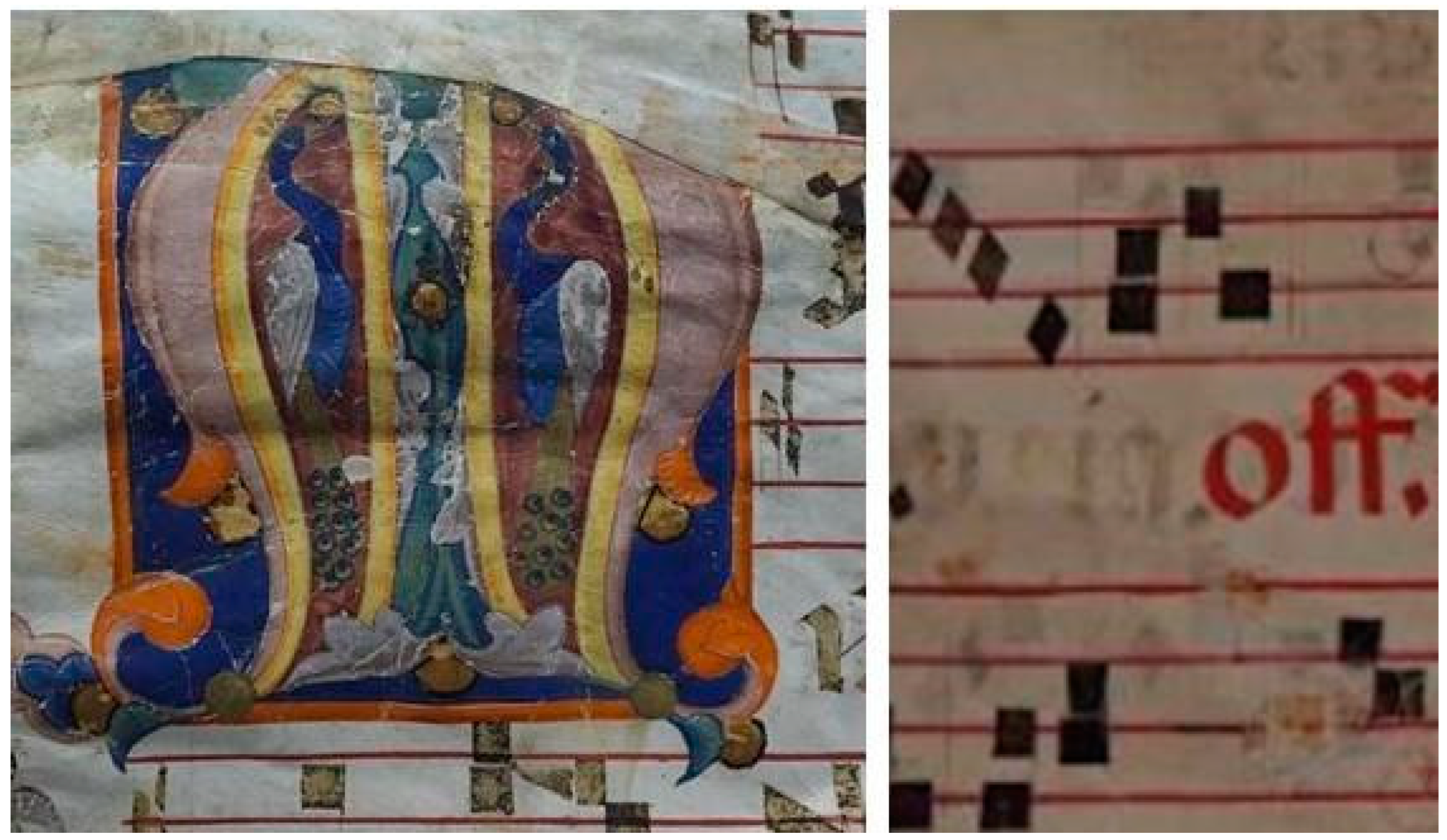
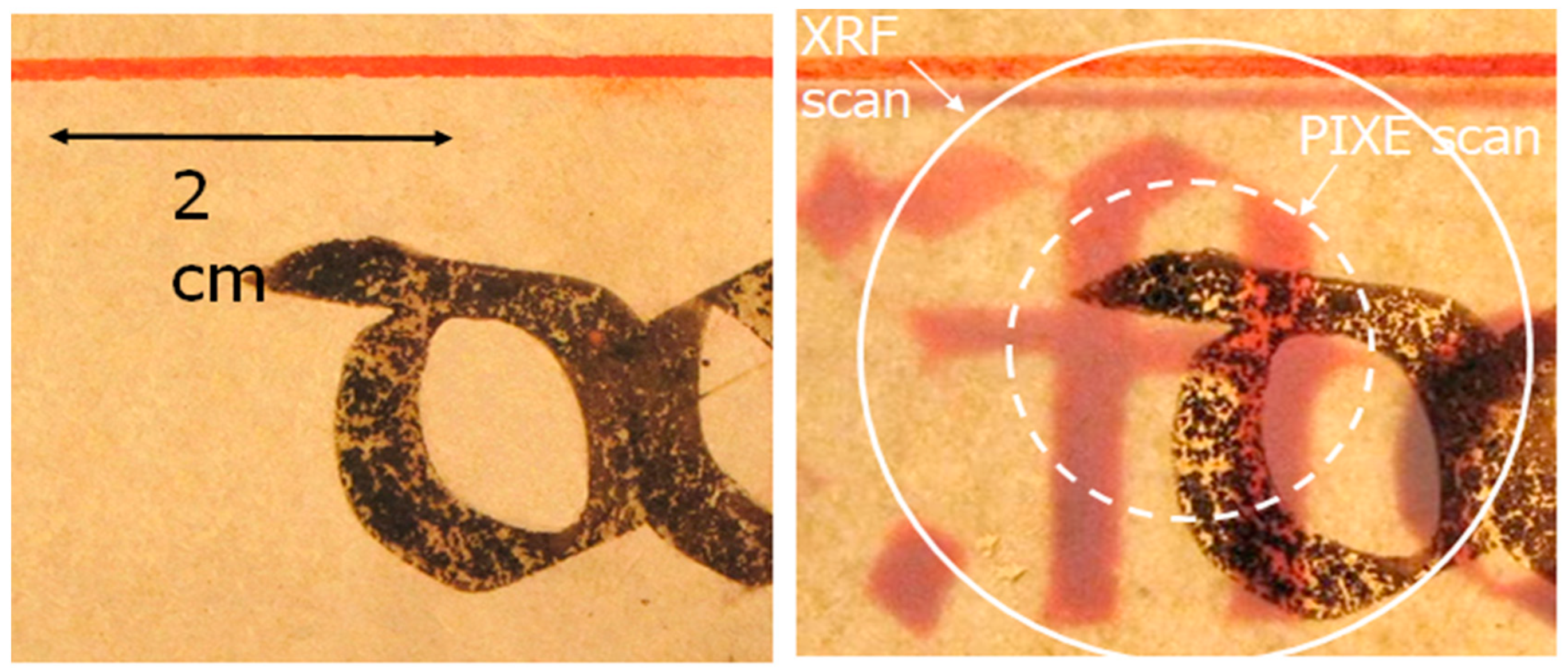
One of the works of art, presented here, is a parchment, a bifolio originally belonging to an antiphonary. It contains a musical notation composed of a system of six tetragrams on each page, with neumes and the text of the chant. It is decorated with calligraphic initials and a figured illuminated letter. Details of the irradiated areas are presented in
Figure 1. Measurements were carried out to characterise the elemental composition of the pigments of the inks.
At the time, the X-rays emitted were detected by two Si(Li) detectors, whose absorbers and whose distances from the sample were chosen so that one was primarily sensitive to elements lighter than Z = 25 and the other to heavier elements. Helium flux was continuously flown in front of the measuring set-up for minimising the argon K-lines production from the atmosphere and to reduce the absorption of low energy X-rays.
The proton current was of the order of a few hundred pA and the energy around 3 MeV; typical acquisition time ranged from a few seconds to a few minutes, with no risk of damaging the target. The proton beam intensity was monitored by rotating a stage with a thin nickel surface layer regularly through the beam and measuring the nickel K X-rays.
For what concerns the pigments, blue and red areas were characterised by the presence of copper and mercury, respectively, suggesting the use of azurite [
35], and of cinnabar/vermilion [
36].
The PIXE spectra of the yellow areas showed the presence of tin, lead, and a significant amount of silicon. After correcting for self-absorption of X-rays within the paint layer, the measured atomic ratio Pb:Sn:Si approximates to 1:0–25:0–65, a result that suggests the presence of lead-tin yellow of type II, Pb(Sn, Si)O
3. This result allows an indirect dating of the miniature since, from studies of lead-tin yellow samples from Italian paintings of the fourteenth and fifteenth centuries, the transition from the use of type II to type I (Pb
2SnO
4) had taken place in Italy around the second quarter of the fifteenth century, as stated in [
37]. The atomic ratio of lead-tin yellow detected here is compatible with type II. Therefore, determining which of these was used may indicate, in a non-destructive and non-invasive way, a
terminus ante quem the miniature was painted.
Green areas showed the presence of copper, lead, tin, and silicon. The Pb:Sn ratio is the same as that in yellow areas. This result led to the hypothesis that green was obtained by mixing lead-tin yellow and a copper-based pigment, such as blue azurite or green malachite [
35]. Further information on this study is included in [
38].
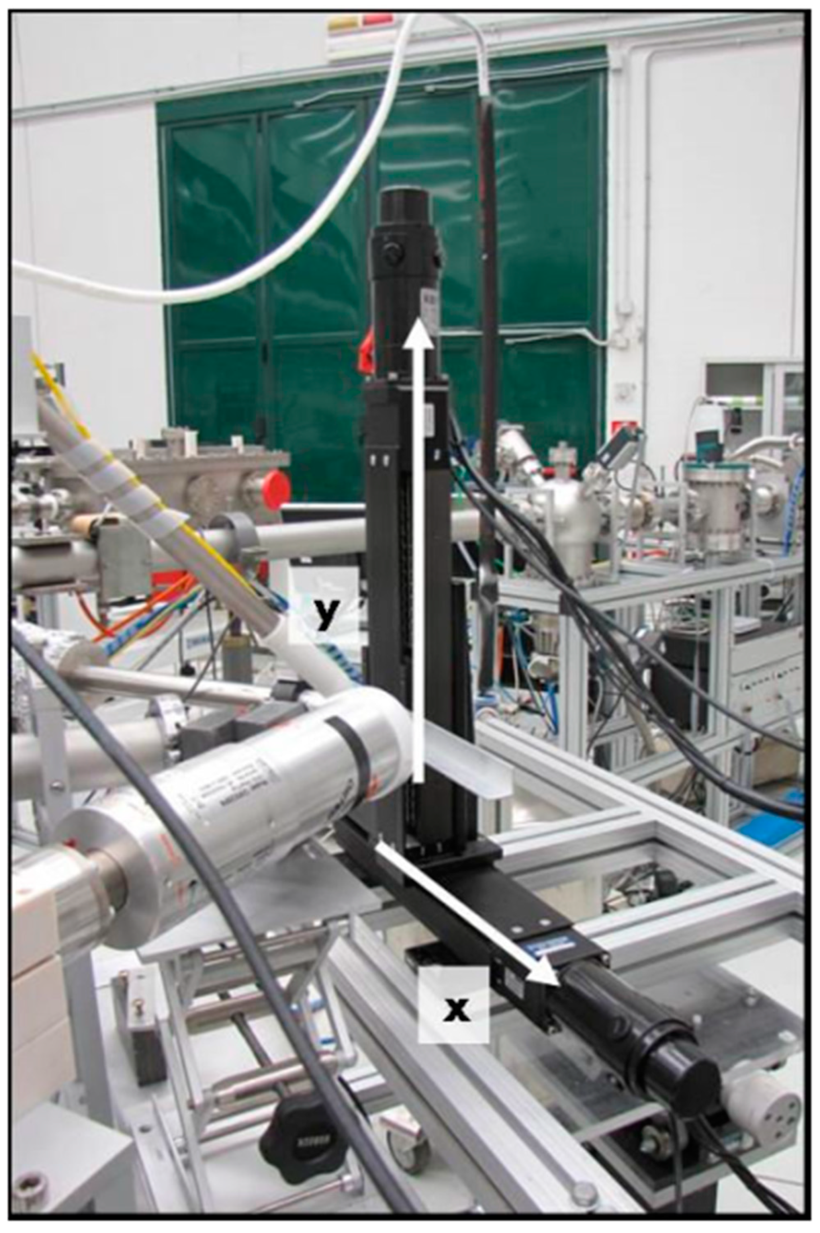
An improvement for scanning an area of the target was achieved using two motor stages (Micos KR-33) and a home-made software for the acquisition. The system was based on continuous motion of the target in the plane perpendicular to the beam direction designed and developed for the beamline, as presented in
Figure 2. Furthermore, a software for the analysis was developed in-home. The spatial distribution of the elements in an area of a few cm
2 was obtained by recording the spectra for each position and selecting the corresponding energy peaks.
The spiral was the scanning mode used since it brings some fundamental advantages. There is no periodical sharp direction change that would impose high acceleration to the sample as in each strip of a raster scan, and the time spent by the beam on each position is rather uniform. The motors complete the first spiral anticlockwise, then stop and retrace the same trajectory clockwise, returning to the initial position. The whole path is inserted in a loop.
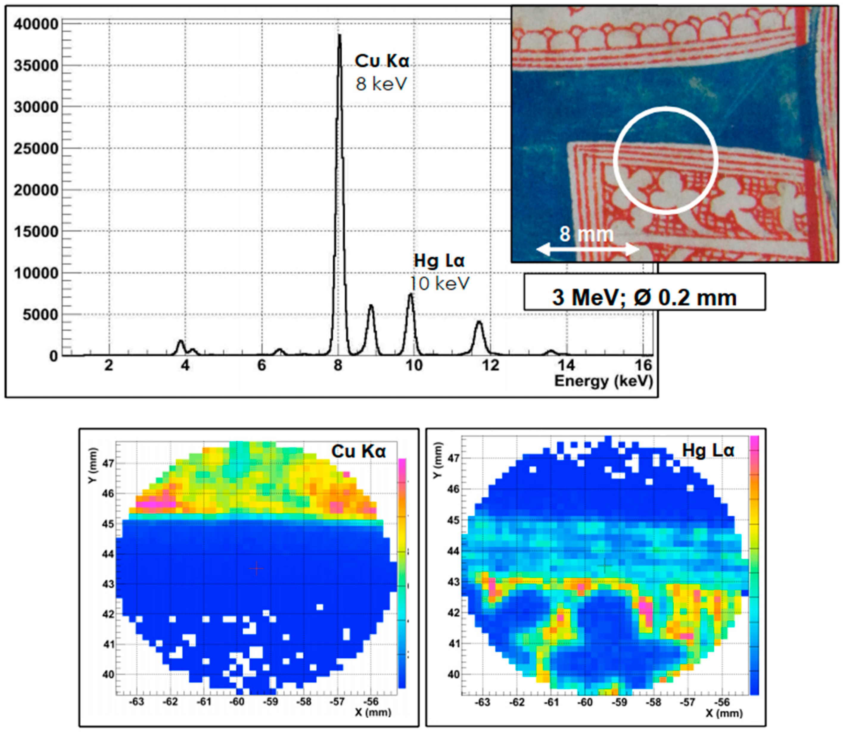
Here a blue penwork initial of the same parchment is reported. The aim is to evaluate the spatial resolution of the scan. To do this, the red decoration was analysed with a proton beam diameter of 0.2 mm. The proton energy was set to 3 MeV and the beam current to few pA. The whole scan lasted about 20 min.
As can be seen in
Figure 3, the blue area is realised with a copper-based pigment, most likely azurite [
35], whereas the red scrolling pattern is made with an Hg-based compound as cinnabar [
36]. The pattern is rather well resolved, despite some local non-homogeneity of the red lines, probably due to the variability of the red ink thickness.
As will be explained in the next section this is, in practice, the lower limit of the spatial resolution achievable by means of mechanical collimation; otherwise, a microbeam facility needs to be used.
It is worth mentioning that in recent years, the Si(Li) detectors have been replaced by Silicon drift detectors [
39]. Their higher efficiency due to the higher solid angle they cover in the set-up, together with their higher energy resolution, and the higher sustainable counting rate, lowers the detection limits, even for shorter measurement times [
40].
4. Technological Advance: The Micro-PIXE Technique at the INFN-LABEC
The capability to produce ion beams with size lower than 100 μm, known as microbeams, has been a natural development of PIXE technique. This is of great importance for samples with microstructures such as biological tissues, geological materials, microelectronic devices, or small specimens such as cultured individual cells, microcrystals, and single aerosol particles.
The simplest way of producing a small beam spot is clearly to use a very fine collimator to select a portion of the beam, as in the case of
Section 3. However, this method presents several drawbacks, the most evident of which is a strong reduction of beam intensity. A second important problem arises because the X-ray detectors’ background increases due the interactions of the stopped beam particles in the collimator bulk. As the collimator aperture is reduced, the stopped beam fraction increases and so the originated background can become unacceptable. In addition, the power dissipated by the stopped beam can noticeably heat the collimator, thus changing its geometrical properties and making the beam size reduction unreliable (especially for very small aperture). Furthermore, the large number of particles hitting the collimator can rapidly deteriorate the aperture edges compromising the quality of the transmitted beam.
However, as a consequence of particle scattering in the aperture, the beam acquires a divergence passing the collimator, one consequence of which is the formation, at a certain distance from the collimator exit, of a scattered beam halo, the size of which depends on the distance from the collimator. As the aperture radius is reduced, the ratio of halo intensity to transmitted beam intensity increases, so that the final effective beam spot size can be much larger than the aperture dimension. Therefore, it is possible to have a fine beam only very close to the collimator, which implies that the distance between sample and collimator should be very short, and this can result in a serious limitation in setting up the detectors.
An ion beam focusing system typically allows overcoming the above mentioned problems with collimated beams. The idea was proposed in 1972 [
41] and it is now at the basis of almost all ion microprobes currently in use. Moreover, the scanning ability, which allows for mapping spatial distribution of the sample elements, was planned to be used. There are two approaches for scanning an area of the sample: sweeping the beam over a static target or moving the target relative to a fixed beam.
Sweeping the beam by electrostatic or magnetic deflection has the advantage that the mechanical design of the target holder is much simplified. In addition, the response time of a swept beam is usually faster than the one of a mechanical stage. When larger areas have to be scanned, the alternative approach is that of sweeping the target under a fixed beam. This also has, in principle, the advantage that the resolution of the beam is not degraded by a worsening of the focusing system; in practice, repeatable mechanical movements are not trivial to achieve to the degree of accuracy implied by the use of a high spatial resolution beam. This method therefore requires careful design and construction, and is much slower than deflecting the beam over the sample using electrostatic or magnetic dipole fields. In addition, the long time required for a mechanical full scan can result in artefacts in elemental maps if long-term beam intensity fluctuations are present and beam charge normalisation is not carried out in every analysed point.
In the scanning system of the microbeam facility at the INFN-LABEC, the beam was swept over the target in horizontal and vertical directions by a magnetic field, perpendicular to the beam direction, generated by ferrite-cored coils positioned immediately before the lens. The magnetic deflector coils allowed, in principle, a maximum scanned area of several mm2 for 3 MeV protons but was, however, limited by the exit window aperture (2 × 2 mm2, typically).
Furthermore, the facility was developed for exploiting and combining the advantages of the two scanning modes, magnetic and mechanical. The magnetic scanning allowed for collecting elemental maps in times faster than the mechanical scanning but within an area limited to ~1 × 1 mm2 by the beam exit window size, whereas the travel range of the motorised stages permitted the possibility to analyse an area on the sample surface up to 25 × 25 mm2. Depending on the case study and on the query, one or both systems could be used.
The number of the beam particles impinging in each point was indirectly measured by counting the number of Si X-rays produced by the beam in the exit window and was used to normalise X-ray yield during measurements. As results from an extensive series of tests, for a given window, the emitted X-rays from the exit window to the collected charge ratio kept constant within 1%, varying the current of two orders of magnitude, from about 10 nA down to about 100 pA.
A summary of the results of the beam profile characteristics, in air or in a helium atmosphere, is shown in
Table 1. The effect of the width of the grid bar (10 μm), used for the measurements, on the profiles is already taken into account [
42].
Among the different applications, this beamline was used to analyse lapis lazuli [
43,
44], a blue semi-precious stone used for more than 7000 years for carved jewels, decorative objects, as well for pigments. This study, besides increasing the knowledge on this blue rock, could shed light on many unresolved questions, especially regarding the trade routes exploited in ancient times.
For those measurements, both μ-PIXE and μ-IBIL (micro–Ion Beam Luminescence) techniques were performed. They allow for analysing single crystals of different mineral phases, a fundamental aspect in a heterogeneous material as lapis lazuli, and they are non-invasive, a necessary feature since it is impossible to take samples from artworks. In this study, different markers were found and proposed to distinguish among the four possible provenances: Afghanistan (Badakhshan), Tajikistan (Pamir Mountains), Siberia (near Lake Baikal), and Chile (Ovalle) [
45].
For example, the presence of diopside (CaMgSi2O6) or wollastonite (CaSiO3) was studied as a potential marker for the Chilean provenance. The presence of wollastonite, due to the double band at 560 and 620 nm, is a clear indication of the Chilean provenance, quickly distinguishable even only by means of luminescence with this set-up. Instead, diopside shows its main IBIL signal band at 585 nm.
As an example of application, six objects of the
Collezione Medicea carved in lapis lazuli were studied in order to obtain some indications about the provenance of the raw material used for their execution [
45]. The absence of wollastonite allowed excluding the Chilean provenance for all the lapis lazuli in these artworks, whereas diopside was detected. Moreover, μ-PIXE results obtained for diopside crystals of these samples show that the titanium, vanadium, and chromium amount are comparable with that in the Afghan rock samples of certain provenance [
46].
Further information about the micro-beam line at INFN-LABEC and additional results can be found in [
47,
48].
5. XRF: From Point Analysis to Elemental Maps with Portable Equipment
The main limit of the PIXE and the other IBA techniques is the lack of portability, a feature that is a severe limitation when a work of art cannot be moved to a laboratory. The XRF technique preserves non-invasive, non-destructive, and multi-elemental characteristics; moreover, it exploits portable instrumentation. For this reason, it is one of the most widely used techniques for material analysis in the field of cultural heritage. Its main drawback is a much lower sensitivity than PIXE to light elements [
49] and the limited possibility of a quantitative analysis in HS [
26].
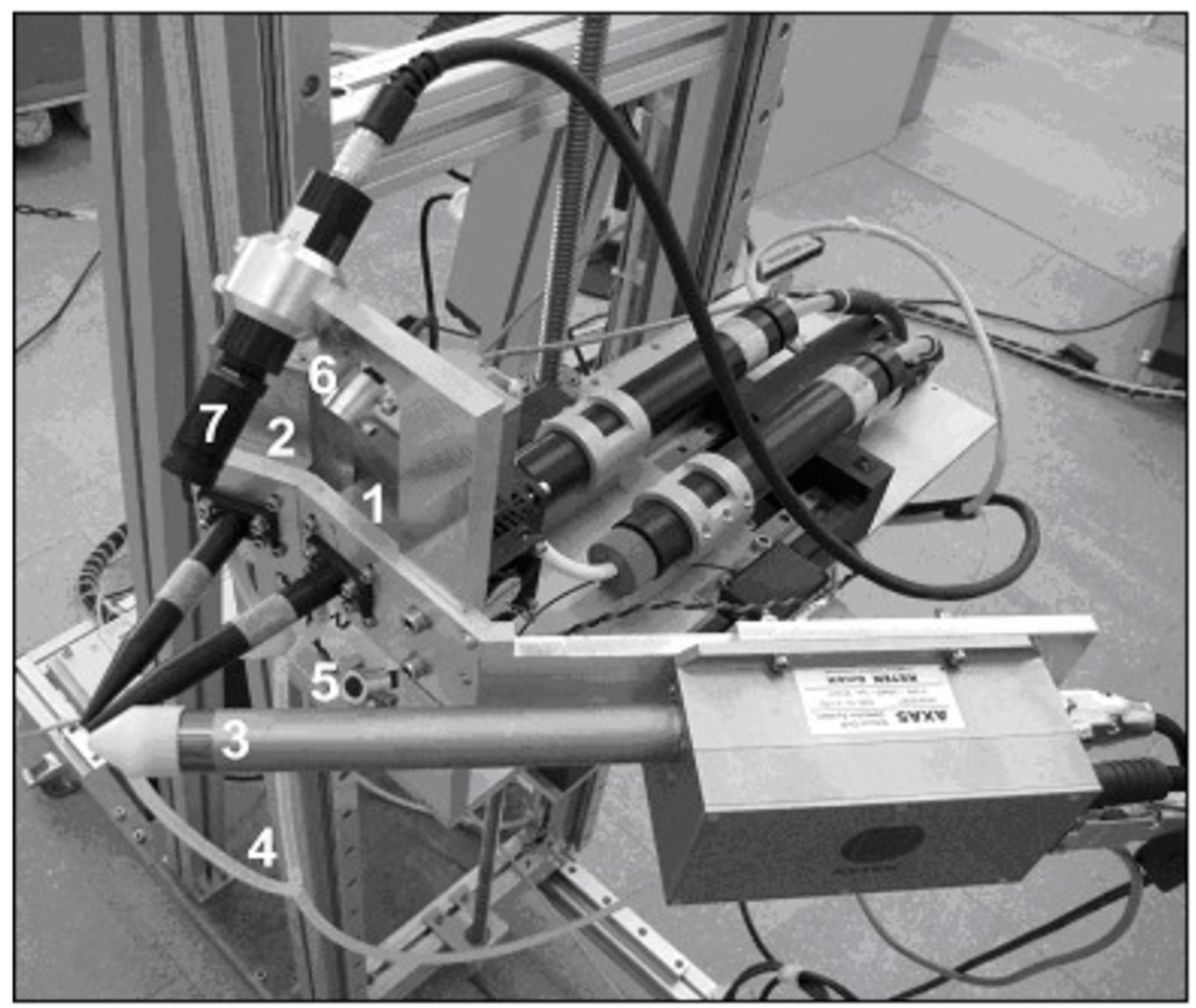
At INFN-LABEC, a portable XRF spectrometer was designed and assembled, exploiting the experience acquired over the years with X-ray spectroscopy using ion beams. In this device, different tubes (Mo, Ti and W anodes available) were used for maximising the efficiency of the production of X-rays over a wide range of energies, as it depends on the main emission lines of the anode material. In addition, since any source emits its own X-rays, and they can hide X-rays emitted by the sample in spectra, the combination of more tubes with different materials limits this effect. For example, the M-lines of Molybdenum at 2.3 keV overlap with the sulphur, whereas the K-lines of Ti (4.5 keV and 4.9 keV) overlap with the L-lines of Barium; therefore, for detecting sulphur, the Ti anode is preferable to Mo, and vice-versa for detecting titanium.
The detector installed was an SDD by Ketek GmbH with an energy resolution of 139 eV at the Mn Kα line. The electronic chain was also supplied by Ketek GmbH and was assembled on the top of the detector case. The entrance window (8 µm thick in beryllium) was located at about 20 mm from the measuring point. Despite the collimation and the quite large distance between tubes and target, the X-ray rate on the detector was satisfactory with current values around 0.3 mA, thanks to the limited target-detector distance. Furthermore, a continuous helium flow in front of the tubes and the detector enhanced the production and detection of low-energy X-rays. The angle between the tubes was reduced as much as possible, to minimise the difference of the two irradiated volumes.
During the measurements, the positioning of the measuring head was obtained through the superposition, on the target surface, of the spots of two appropriately aimed lasers. The measuring area was continuously monitored through a camera. The instrument is presented in
Figure 4.
Among the many applications, see for example [
50,
51]. This instrument was also successfully employed for the discrimination between polishing methods of Japanese swords, or “katanas”.
Katanas have the high features of hardness and elasticity of steel and require a long polishing process traditionally carried out with a layer of clay mixed with charcoal after forging. Polishing of the blade can be repeated for maintenance during their life. A fast method to visually imitate a traditional polishing process is to use an acid bath to mimic the aspect of the undamaged blade but, in spite of a good appearance, the martensitic structure of the sword becomes severely damaged. It is worth noting that on the market their price can vary from a few k€ for a damaged blade to tens of k€ for a well-preserved one. Thus, a doable way to analytically distinguish the two methods is to detect silicon traces left by the stone-based traditional polishing method.
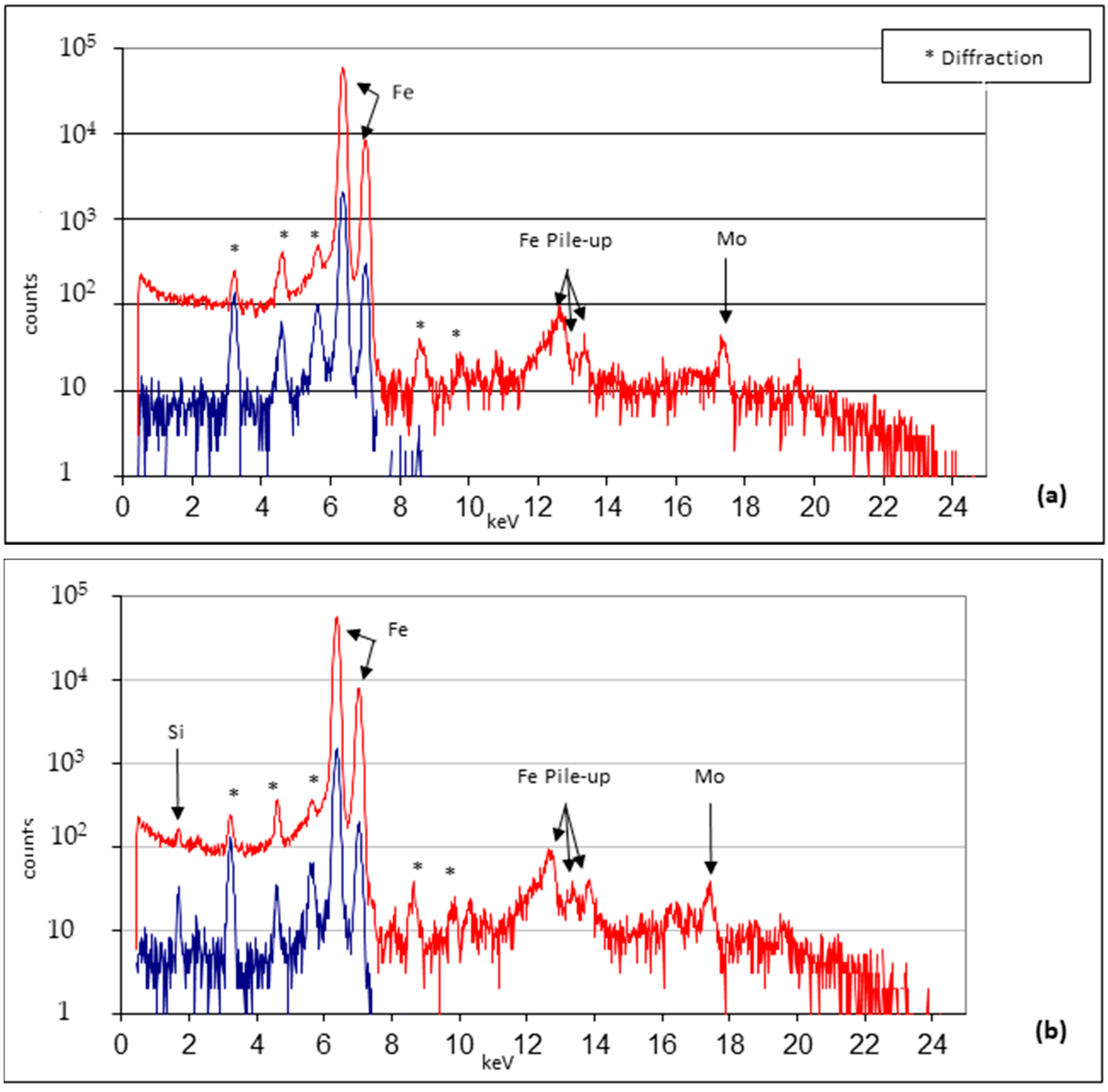
For the study, a set of katanas, both damaged and well-conserved, from the Stibbert Museum of Florence, were analysed, exploiting the XRF spectrometer. The measurements were conducted with Mo anode at 9 kV and 25 kV anode voltages. As can be seen from
Figure 5, the silicon peak is present in the blade conserved with traditional methods, whereas the other does not show any evidence of the presence of silicon.
The measurements were conducted on a set of 13 katanas, confirming the goodness of this method to distinguish between the two groups of katanas. Further information is available in the publication [
52].
6. Comparison between PIXE and XRF Techniques at the INFN-LABEC
As a practical example, here, the same area of the parchment irradiated at the PIXE beamline described in
Section 3 is reported and with the XRF spectrometer presented in
Section 5. The scan was conducted with the motor system shown in
Figure 2. Experimental parameters are reported in
Table 2 and the areas measured are presented in
Figure 6.
As can be seen from the backlit picture (
Figure 6), lyrics are present on the backside of the bifolio.
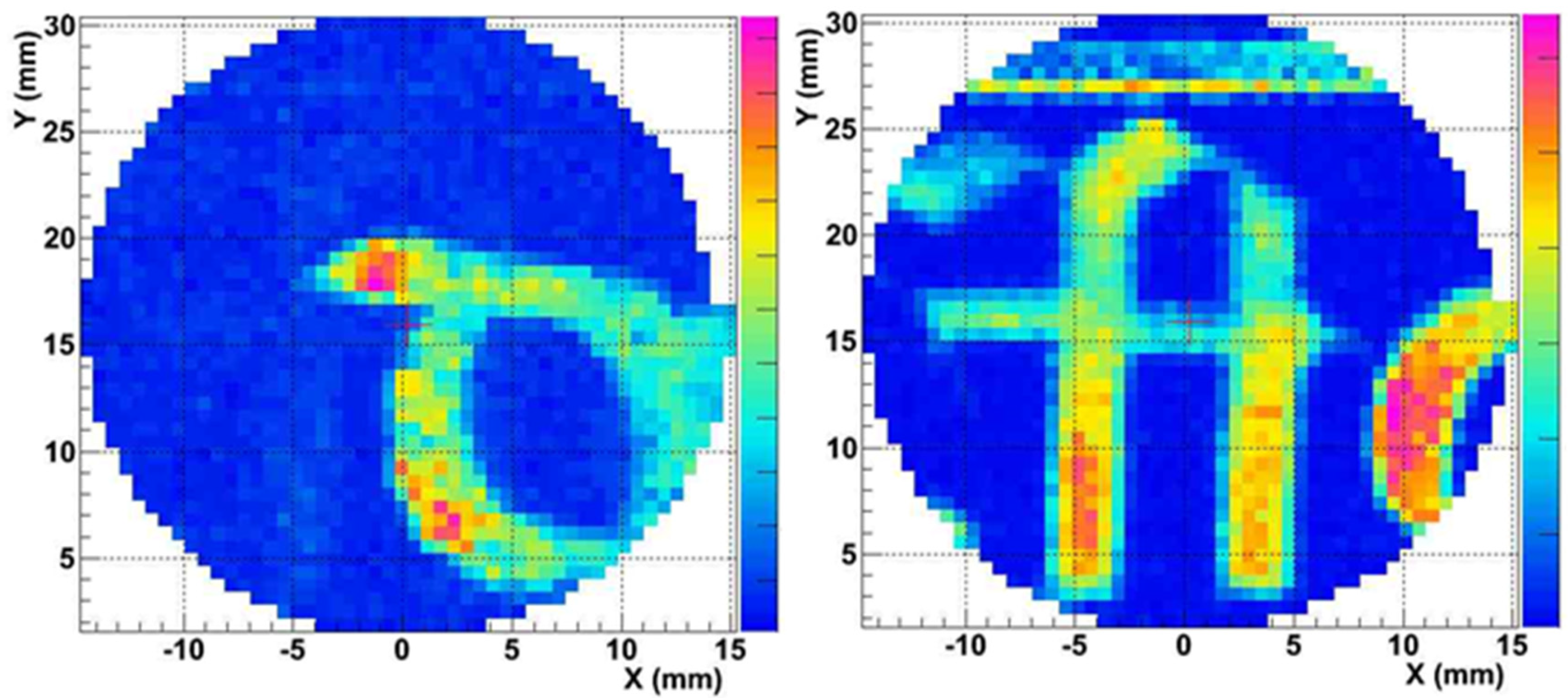
Results of the irradiation are presented in
Figure 7 and
Figure 8. As can be seen from
Figure 7, with XRF it is possible to detect the ink from the two sides of the parchment, both iron from the front side (
Figure 7, left) and mercury (
Figure 7, right).
On the contrary, with the PIXE technique, only the ink on the front side was clearly detected, whereas the letter on the other side is not clearly visible from the map of mercury.
This result is a consequence of the higher penetration depth of XRF in comparison with PIXE. This can be considered an example of the advantage of matching the two techniques; indeed, the detection of the materials on the verso of the folio together with those on the recto may complicate the reading. On the other hand, two materials can be detected with only one measurement (easily distinguishable thanks to the mapping methods) and, moreover, the eventual interaction with these materials may be observed.
7. Technological Advances: INFN-CHNet MA-XRF Scanner
As for the PIXE technique, a natural development of the XRF technique is to allow scanning without disclaiming the portability of the device. With this aim, within the INFN-CHNet group, a MA-XRF scanner was designed with a special focus on portability and lightness. The technical characteristics and analytical capabilities (detection efficiency, spatial resolution, etc.) of this equipment are thoroughly described in [
53], and only the main characteristics are reported here. The measuring head of the instrument is composed of an X-ray tube by Moxtek (40 kV maximum voltage, 0.1 mA maximum anode current) and an SDD detector by Amptek (XR100 SDD, 25 mm
2 effective active surface, 500 μm thickness). A telemeter by Keyence (model IA-100) is also placed on the measuring head for the on-line control and adjustment of the sample-instrument distance. This measuring head is mounted on three linear motor stages by Physik Instrumente, with a 200 mm travel range in the x and y directions for this version, plus a 50 mm stage along the z perpendicular direction. The whole system is placed on a carbon-fibre box containing motor controllers, a multi-channel analyser (model CAEN DT-5780), and other electrical components. The software controlling acquisition and data analysis is entirely developed by researchers of the INFN-CHNet group. The instrument has been successfully employed in several HS applications over the years and, thanks to its versatility, it is a matter of continuous upgrade.
With the use of the scanner, the painting techniques of the Old Masters, such as Raffaello [
54] and Van der Weyden [
55] were conducted. In the painting
La Muta by Raffaello, the painting palette was characterised and a
pentimento—the presence or emergence of earlier images, forms, or strokes that have been changed and painted over by the author—was found. In the work
Entombment of Christ by Van der Weyden, the painting technique—in particular the use of powdered glass in mixture with the pigments—was studied.
Further type of works of art analysed with this instrument are Venetian illuminated manuscripts [
56], furniture of the XVIII century [
57], and French ceramics [
58].
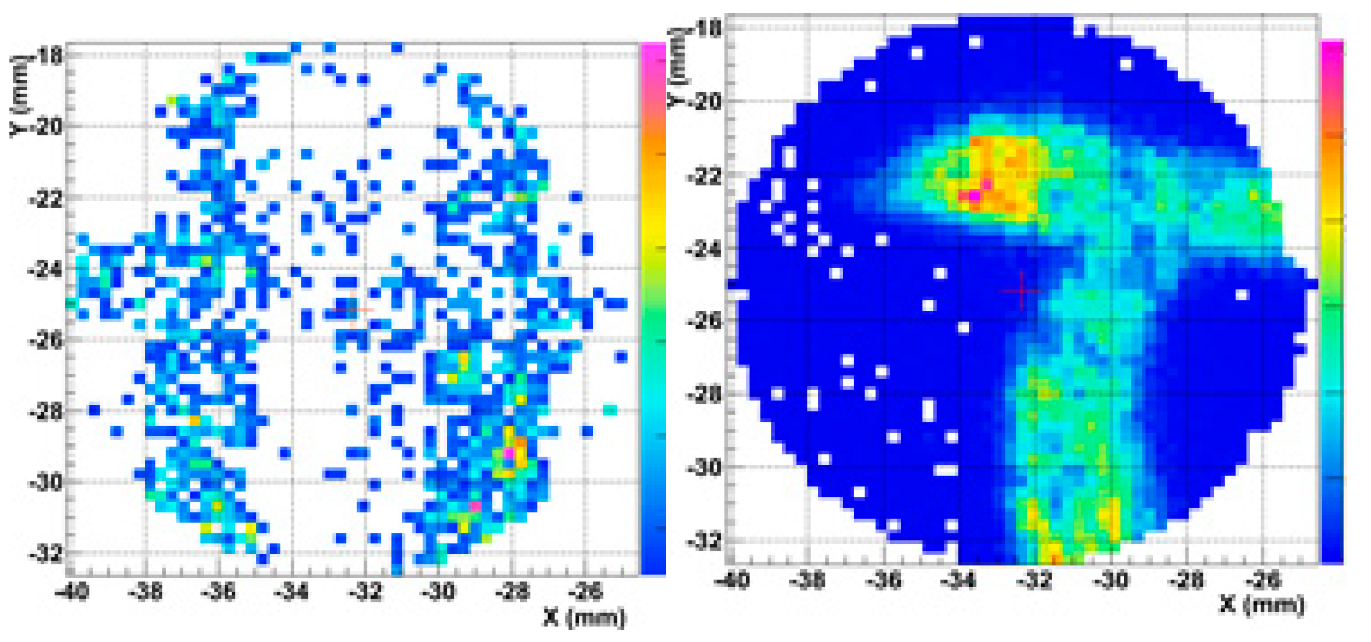
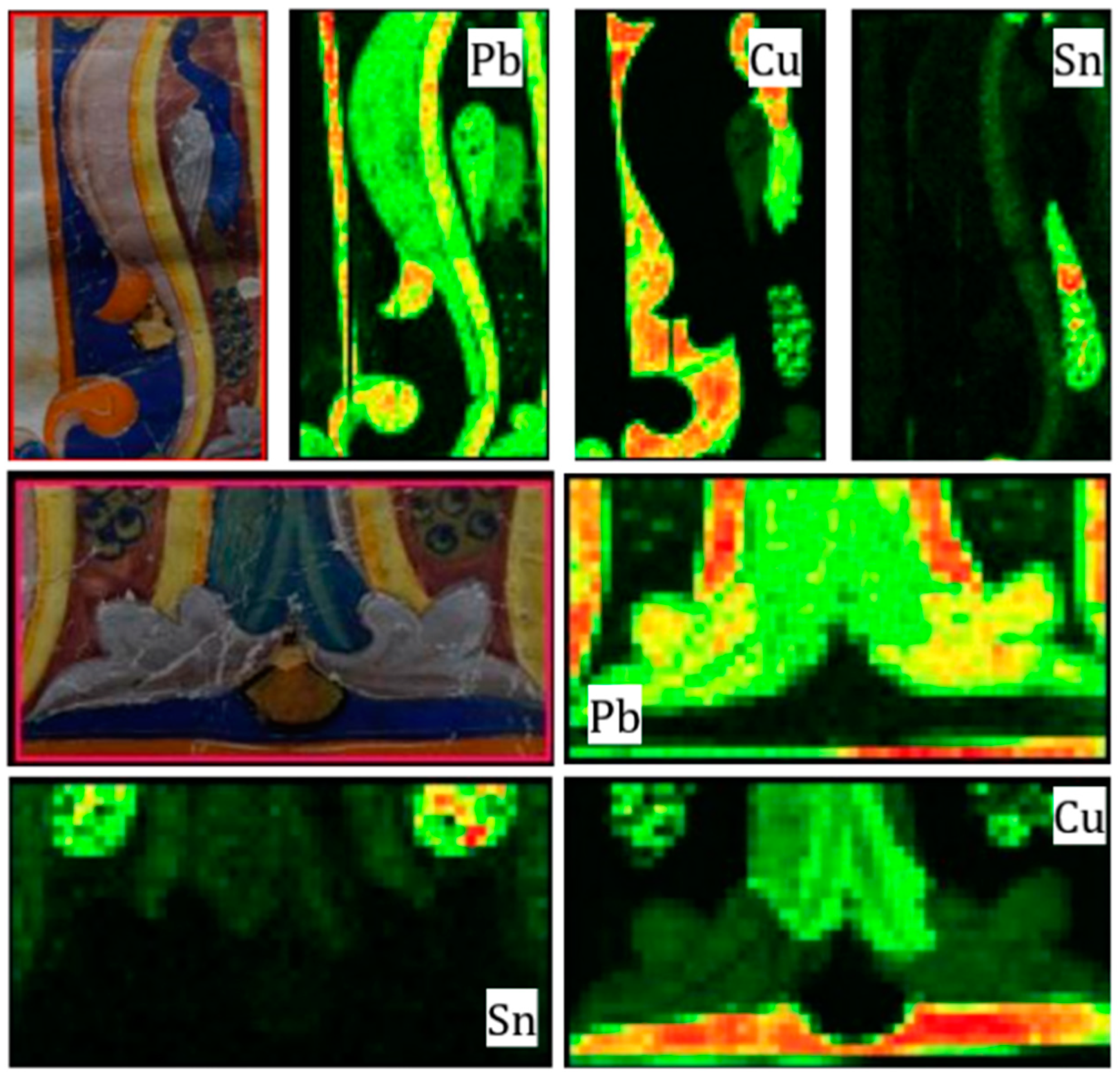
Here are presented elemental maps of two areas around the initial of the same parchment presented in
Section 3. During the measurements, a preliminary version of the scanner was used with a chromium anode. The operating conditions of the X-ray tube for all measurements were: 30 kV anode voltage, 0.1 mA current, and an 800 μm diameter collimator was used. The scanning velocity was set to 1 mm/s.
Comparing the maps with the measurements conducted in
Section 3 and
Section 5, the advantage of a scanning system is evident: it is straightforward to match the visible pattern with the elemental distribution and therefore to identify the material that was probably used for the painting layer.
The elemental maps are shown in
Figure 9. The blue colour—the background and the body of the peacock—is painted with a copper-based pigment, most likely azurite [
35]. The tail of the peacock is characterised by the presence of tin, in this case probably indicating the presence of mosaic gold [
59]. Blue eyespots of the feathers are likely painted with azurite as the body of the peacock. Lead and tin are detected in the yellow outline of the initial, suggesting the use of lead-tin yellow [
59]. The light grey wings and decorative leaves are characterised by the presence of lead and of copper traces, most likely due to the use of lead white and little amount of azurite. It is worth noting that the use of other organic compounds cannot be conclusively identified with this technique, but the fact that the pink initial is characterised only by the presence of lead (usually lead white or red lead) is a strong hint of the use of a red organic dye.
Thanks to the versatility of the scanner, further developments of it are under study. As an example, the likely combination of different techniques using the same X-ray source is under study. Results of the combination of the XRF with digital radiography is presented in [
60].
The limit of this technique is of course related to the fact that it allows only elemental analysis. This is of course a limit for the analysis of a number of materials, such as glasses, for which it is important to determine the polymerisation degree of enamels successfully evaluated with Raman spectroscopy [
61].
8. The MACHINA Project
The strong demand of scientific analysis for conservation and preservation of works of art led to the project of an instrument with the same performance as the standard IBA techniques (effectiveness and sensitivity, non-invasiveness and non-destructiveness), with the additional features of transportability, lightness, and low power consumption. To answer the query, the INFN-CHNet group, in collaboration with the Conseil Europèen pour la Recherce Nuclèaire (CERN) and the Opificio delle Pietre Dure (OPD) in Florence, a world-renowned conservation institution, has started the MACHINA project [
62], an accelerator of about 600 kg weight, with a footprint of about 2.5 m × 1.6 m, services included, and a power consumption of a few kW. It will produce 2 MeV proton beams thanks to a RadioFrequency source and an high-frequency RFQ accelerating part. The RF source produces 20 keV protons that will be delivered into the Low Energy Beam Transport (LEBT) line, which consists of a focusing stage and a diagnostic station. The beam will then be injected in the HF-RFQ, where it is focused and accelerated to the final energy of 2 MeV. A permanent magnet quadrupole doublet focusing system and a second diagnostic station will be installed downstream before the beam extraction in air. Moreover, it will be possible to insert two beam energy degraders to lower the proton beam energy.
The detection system of MACHINA has been designed to hold two SDD detectors for PIXE analysis, each optimised for the acquisition of different X-ray ranges, and one CdTe detector for Particle Induced Gamma-ray emission (PIGE) analysis. Another SDD detector will monitor the beam current detecting the X-rays emitted by the exit window. As underlined in the article [
27], with the expertise of the INFN-CHNet group with detector systems, other techniques can be added to the ones already planned.
9. Conclusions
In this review, the facilities dedicated to PIXE and XRF techniques in air developed at the INFN-LABEC laboratory have been described. Starting from the first PIXE beamline, thanks to the expertise of the group, the equipment for the irradiation of micrometric areas (the microbeam line) and for in situ analysis (XRF spectrometer) were developed.
Currently, within the INFN-CHNet collaboration, a MA-XRF scanner is fully operative for mapping works of art. Furthermore, a device for in-situ PIXE analysis is in progress. It will be the first transportable accelerator based on the RFQ technique and will make available IBA techniques in museums and conservation centres.
Author Contributions
Conceptualization, P.A.M., F.T., L.G. (Lorenzo Giuntini) and A.L.G.; methodology, P.A.M., F.T. and L.G. (Lorenzo Giuntini); software, F.T., C.C. and R.T.; formal analysis, L.C. (Lisa Castelli), S.M.E.M., A.M., C.R., S.C. and A.R.; investigation, L.C. (Luca Carraresi) and M.M. (Marco Manetti); data curation, F.G. and L.C. (Lisa Castelli); writing—original draft preparation, L.S., A.M., M.M. (Mirko Massi) and L.G. (Lorenzo Giuntin); writing—review and editing, A.R., L.G. (Laura Guidorzi), L.G. (Lorenzo Giuntini), M.M. (Mirko Massi), L.S. and A.M.; visualization, L.C. (Luca Carraresi), L.S. and S.M.E.M.; supervision, F.A., P.A.M. and L.G. (Lorenzo Giuntini); project administration, P.A.M., L.G. (Lorenzo Giuntini), F.T. and A.L.G. All authors have read and agreed to the published version of the manuscript.
Funding
The research was funded within the INFN-CHNet project. This project has received funding from the European Union’s Horizon 2020 research and innovation programme under the Marie Skłodowska-Curie grant agreement No 754511 (PhD Technologies Driven Sciences: Technologies for Cultural Heritage—T4C).
Institutional Review Board Statement
Not applicable.
Informed Consent Statement
Not applicable.
Acknowledgments
The authors wish to warmly thank Paulene Linda Healey and Hilary Peebles from the University Language Centre at the University of Florence for their invaluable linguistic support.
Conflicts of Interest
The authors declare no conflict of interest.
References
- Castoldi, A.; Guazzoni, C.; Mezza, D.; Montemurro, G.V.; Carraresi, L.; Taccetti, F. Upgrade of the DEFEL proton beam line for detector response mapping. In Proceedings of the 2013 IEEE Nuclear Science Symposium and Medical Imaging Conference (2013 NSS/MIC), Seoul, Korea, 27 October–2 November 2013; pp. 1–5. [Google Scholar] [CrossRef]
- Bardelli, L.; Bini, M.; Bizzeti, P.G.; Carraresi, L.; Danevich, F.A.; Fazzini, T.F.; Grinyov, B.V.; Ivannikova, N.V.; Kobychev, V.V.; Kropivyansky, B.N.; et al. Further study of CdWO4 crystal scintillators as detectors for high sensitivity 2β experiments: Scintillation properties and pulse-shape discrimination. Nucl. Instrum. Methods Phys. Res. Sect. A Accel. Spectrometers Detect. Assoc. Equip. 2006, 569, 743–753. [Google Scholar] [CrossRef]
- Rocchini, M.; Hadyńska-Klȩk, K.; Nannini, A.; Valiente-Dobón, J.J.; Goasduff, A.; Testov, D.; Mengoni, D.; John, P.R.; Siciliano, M.; Melon, B. SPIDER: A Silicon PIe DEtectoR for low-energy Coulomb-excitation measurements. Nucl. Instrum. Methods Phys. Res. Sect. A Accel. Spectrometers Detect. Assoc. Equip. 2020, 971, 164030. [Google Scholar] [CrossRef]
- Lagomarsino, S.; Flatae, A.M.; Kambalathmana, H.; Sledz, F.; Hunold, L.; Soltani, N.-; Reuschel, P.; Sciortino, S.; Gelli, N.; Massi, M.; et al. Creation of Silicon-Vacancy Color Centers in Diamond by Ion Implantation. Front. Phys. 2021, 8, 601362. [Google Scholar] [CrossRef]
- Petrucci, F.; Caforio, L.; Fedi, M.; Mandò, P.; Peccenini, E.; Pellicori, V.; Rylands, P.; Schwartzbaum, P.; Taccetti, F. Radiocarbon dating of twentieth century works of art. Appl. Phys. A 2016, 122, 983. [Google Scholar] [CrossRef]
- Nava, S.; Calzolai, G.; Chiari, M.; Giannoni, M.; Giardi, F.; Becagli, S.; Severi, M.; Traversi, R.; Lucarelli, F. Source Apportionment of PM2.5 in Florence (Italy) by PMF Analysis of Aerosol Composition Records. Atmosphere 2020, 11, 484. [Google Scholar] [CrossRef]
- Lucarelli, F. How a small accelerator can be useful for interdisciplinary applications: The study of air pollution. Eur. Phys. J. Plus 2020, 135, 538. [Google Scholar] [CrossRef]
- Calusi, S. The External Ion Microbeam of the LABEC Laboratory in Florence: Some Applications to Cultural Heritage. Microsc. Microanal. 2011, 17, 661–666. [Google Scholar] [CrossRef]
- Taccetti, N.; Giuntini, L.; Casini, G.; Stefanini, A.A.; Chiari, M.; Fedi, M.E.; Mandò, P.A. The pulsed beam facility at the 3 MV Van de Graaff accelerator in Florence: Overview and examples of applications. Nucl. Instrum. Methods Phys. Res. Sect. B Beam Interact. Mater. Atoms 2002, 188, 255–260. [Google Scholar]
- Lagomarsino, S.; Sciortino, S.; Gelli, N.; Flatae, A.M.; Gorelli, F.; Santoro, M.; Chiari, M.; Celusniak, C.; Giuntini, L. The center for production of single-photon emitters at the electrostatic-deflector line of the Tandem accelerator of LABEC (Florence). Nucl. Instruments Methods Phys. Res. Sect. B Beam Interactions Mater. Atoms 2018, 422, 31–40. [Google Scholar] [CrossRef]
- Chiari, M.; Melon, B.; Salvestrini, L.; Fonseca, M.; Alves, E.; Jesus, A.P. Measurement of proton induced γ-ray emission cross-sections on Al from 2.5 to 4.1 MeV. Nucl. Instrum. Methods Phys. Res. Sect. B 2014, 332, 355–358. [Google Scholar] [CrossRef]
- Palla, L.; Castelli, L.; Czelusniak, C.; Fedi, M.; Giuntini, L.; Liccioli, L.; Mandò, P.; Martini, M.; Mazzinghi, A.; Ruberto, C.; et al. Preliminary measurements on the new TOF system installed at the AMS beamline of INFN-LABEC. Nucl. Instrum. Methods Phys. Res. Sect. B Beam Interact. Mater. Atoms 2015, 361, 222–228. [Google Scholar] [CrossRef]
- Mandò, P. The Florence accelerator laboratory for Ion Beam Analysis and AMS radiocarbon dating. Il Nuovo Cim. C 2007, 30, 85–92. [Google Scholar] [CrossRef]
- Chiari, M.; Barone, S.; Bombini, A.; Calzolai, G.; Carraresi, L.; Castelli, L.; Czelusniak, C.; Fedi, M.E.; Gelli, N.; Giambi, F.; et al. LABEC, the INFN ion beam laboratory of nuclear techniques for environment and cultural heritage. Eur. Phys. J. Plus 2021, 136, 472. [Google Scholar] [CrossRef] [PubMed]
- Czelusniak, C.; Palla, L.; Massi, M.; Carraresi, L.; Giuntini, L.; Re, A.; Lo Giudice, A.; Pratesi, G.; Mazzinghi, A.; Ruberto, C.; et al. Preliminary results on time-resolved ion beam induced luminescence applied to the provenance study of lapis lazuli. Nucl. Instrum. Methods Phys. Res. B 2016, 371, 336–339. [Google Scholar]
- Palla, L.; Czelusniak, C.; Taccetti, F.; Carraresi, L.; Castelli, L.; Fedi, M.E.; Giuntini, L.; Maurenzig, P.R.; Sottili, L.; Taccetti, N. Accurate on line measurements of low fluences of charged particles. Eur. Phys. J. Plus 2015, 130, 39. [Google Scholar] [CrossRef][Green Version]
- Janssens, K.; Vincze, L.; Rubio, J.; Adams, F.; Bernasconi, G. Microscopic X-ray fluorescence analysis. Invited lecture. J. Anal. At. Spectrom. 1994, 9, 151–157. [Google Scholar] [CrossRef]
- Ishii, K. PIXE and Its Applications to Elemental Analysis. Quantum Beam Sci. 2019, 3, 12. [Google Scholar] [CrossRef]
- Ricciardi, P.; Mazzinghi, A.; Legnaioli, S.; Ruberto, C.; Castelli, L. The Choir Books of San Giorgio Maggiore in Venice: Results of in Depth Non-Invasive Analyses. Heritage 2019, 2, 1684–1701. [Google Scholar] [CrossRef]
- Vadrucci, M.; Mazzinghi, A.; Sorrentino, B.; Falzone, S.; Gioia, C.; Gioia, P.; Loreti, E.M.; Chiari, M. Characterisation of ancient Roman wall-painting fragments using non-destructive IBA and MA-XRF techniques. X-ray Spectrom. 2020, 49, 668–678. [Google Scholar] [CrossRef]
- Calligaro, T.; Banas, A.; Banas, K.; Radović, I.B.; Brajković, M.; Chiari, M.; Forss, A.-M.; Hajdas, I.; Krmpotić, M.; Mazzinghi, A.; et al. Emerging nuclear methods for historical painting authentication: AMS-14C dating, MeV-SIMS and O-PTIR imaging, global IBA, differential-PIXE and full-field PIXE mapping. Forensic Sci. Int. 2022, 336, 111327. [Google Scholar] [CrossRef]
- Available online: https://www.amptek.com/products/mini-x2-x-ray-tube (accessed on 28 May 2022).
- Available online: https://calc.weingos.com/ (accessed on 28 May 2022).
- Lekki, J.; Matosz, M.; Paluszkiewicz, C.; Pięta, E.; Pieprzyca, T.; Szklarz, Z.; Meléndez, J.M.D.H. Comparison of PIXE and XRF in the analysis of silver denarii of the early Piast. J. Radioanal. Nucl. Chem. 2017, 314, 2309–2316. [Google Scholar] [CrossRef] [PubMed]
- Mandò, P.A.; Przybyłowicz, W.J. Particle-Induced X-ray Emission (PIXE). In Encyclopedia of Analytical Chemistry; Meyers, R.A., Ed.; John Wiley & Sons: New York, NY, USA, 2009. [Google Scholar] [CrossRef]
- Bonizzoni, L. ED-XRF analysis for Cultural Heritage: Is quantitative evaluation always essential? J. Phys. Conf. Ser. 2015, 630, 12001. [Google Scholar] [CrossRef]
- Giuntini, L.; Castelli, L.; Massi, M.; Fedi, M.; Czelusniak, C.; Gelli, N.; Liccioli, L.; Giambi, F.; Ruberto, C.; Mazzinghi, A.; et al. Detectors and Cultural Heritage: The INFN-CHNet Experience. Appl. Sci. 2021, 11, 3462. [Google Scholar] [CrossRef]
- Käyhkö, M.; Laitinen, M.; Arstila, K.; Maasilta, I.; Sajavaara, T. A new beamline for energy-dispersive high-resolution PIXE analysis using polycapillary optics. Nucl. Instrum. Methods Phys. Res. Sect. B Beam Interact. Mater. Atoms 2019, 447, 59–67. [Google Scholar] [CrossRef]
- Hanf, D.; Buchriegler, J.; Renno, A.D.; Merchel, S.; Munnik, F.; Ziegenrücker, R.; Scharf, O.; Nowak, S.H.; von Borany, J. A new Particle-Induced X-ray Emission set-up for laterally resolved analysis over wide areas. Nucl. Instr. Methods Phys. Res. B 2016, 377, 17–24. [Google Scholar] [CrossRef]
- Romano, F.P.; Caliri, C.; Nicotra, P.; di Martino, S.; Pappalardo, L.; Rizzo, F.; Santos, H.C. Real-time elemental imaging of large dimension paintings with a novel mobile macro X-ray fluorescence (MA-XRF) scanning technique. J. Anal. At. Spectrom. 2017, 32, 773–781. [Google Scholar] [CrossRef]
- Alfeld, M.; Pedroso, J.V.; van EikemaHommes, M.; Van der Snickt, G.; Tauber, G.; Blaas, J.; Haschke, M.; Erler, K.; Dik, J.; Janssens, K. A mobile instrument for in situ scanning macro-XRF investigation of historical paintings. J. Anal. At. Spectrom. 2013, 28, 760–767. [Google Scholar] [CrossRef]
- Mihalic, I.B.; Fazinic, S.; Barac, M.; Karydas, A.G.; Migliori, A.; Doracic, D.; Desnica, V.; Mudronja, D.; Krstic, D. Multivariate analysis of PIXE plus XRF and PIXE spectral images. J. Anal. At. Spectrom. 2021, 36, 654–667. [Google Scholar] [CrossRef]
- Giuntini, L.; Lucarelli, F.; Mandò, P.; Hooper, W.; Barker, P. Galileo’s writings: Chronology by PIXE. Nucl. Instrum. Methods Phys. B 1995, 95, 389–392. [Google Scholar] [CrossRef]
- Carmine, P.; Giuntini, L.; Hooper, W.; Lucarelli, F.; Mandò, P. Further results from PIXE analysis of inks in Galileo’s notes. Nucl. Instrum. Methods Phys. Res. Sect. B Beam Interact. Mater. Atoms 1996, 113, 354–358. [Google Scholar] [CrossRef]
- Roy, A. (Ed.) Artists’ Pigments: A Handbook of Their History and Characteristics; National Gallery of Art, Washington Archetype Publications: London, UK, 1993; Volume 2. [Google Scholar]
- Gettens, R.J.; Robert, L.F.; Chase, W.T. Vermilion and Cinnabar. Stud. Conserv. 1972, 17, 45–69. [Google Scholar]
- KUHN, H. ‘Lead-tin yellow’. Stud. Conserv. 1968, 13, 7–33. [Google Scholar]
- Bussotti, L.; Giuntini, L.; Carboncini, M.P.; Mandò, P.A.; Castellucci, E. Identification of Pigments in a Fourteenth-Century Miniature by Combined Micro-Raman and Pixe Spectroscopic Techniques. Stud. Conserv. 1997, 42, 83–92. [Google Scholar] [CrossRef]
- Gatti, E.; Rehak, P.; Walton, J.T. Silicon drift chambers—First results and optimum processing of signals. Nucl. Instrum. Methods Phys. Res. Sect. A Accel. Spectrom. Detect. Assoc. Equip. 1984, 226, 129–141. [Google Scholar] [CrossRef]
- Lucarelli, F.; Calzolai, G.; Chiari, M.; Giannoni, M.; Mochi, D.; Nava, S.; Carraresi, L. The upgraded external-beam PIXE/PIGE set-up at LABEC for very fast measurements on aerosol samples. Nucl. Instrum. Methods Phys. Res. Sect. B Beam Interact. Mater. Atoms 2014, 318, 55–59. [Google Scholar] [CrossRef]
- Cookson, J.A.; Ferguson, A.T.G.; Pilling, F.D. Proton microbeams, their production and use. J. Radioanal. Chem. 1972, 12, 39–52. [Google Scholar] [CrossRef]
- Massi, M. The ion microbeam facility of Florence: A versatile instrument for the analysis and modification of materials. Il Nuovo Cim. C 2011, 34, 91–102. [Google Scholar]
- Re, A.; Lo Giudice, A.; Angelici, D.; Calusi, S.; Giuntini, L.; Massi, M.; Pratesi, G. Lapis lazuli provenance study by means of micro-PIXE. Nucl. Instrum. Methods Phys. Res. B 2011, 269, 2373–2377. [Google Scholar] [CrossRef]
- Re, A.; Angelici, D.; Lo Giudice, A.; Maupas, E.; Giuntini, L.; Calusi, S.; Gelli, N.; Massi, M.; Borghi, A.; Gallo, L.M.; et al. New markers to identify the provenance of lapis lazuli: Trace elements in pyrite by means of micro-PIXE. Appl. Phys. A 2013, 111, 69–74. [Google Scholar] [CrossRef]
- Lo Giudice, A.; Angelici, D.; Re, A.; Gariani, G.; Borghi, A.; Calusi, S.; Giuntini, L.; Massi, M.; Castelli, L.; Taccetti, F.; et al. Protocol for lapis lazuli provenance determination: Evidence for an Afghan origin of the stones used for ancient carved artefacts kept at the Egyptian Museum of Florence (Italy). Archaeol. Anthropol. Sci. 2017, 9, 637–651. [Google Scholar] [CrossRef]
- Re, A.; Angelici, D.; Giudice, A.L.; Corsi, J.; Allegretti, S.; Biondi, A.F.; Gariani, G.; Calusi, S.; Gelli, N.; Giuntini, L.; et al. Ion Beam Analysis for the provenance attribution of lapis lazuli used in glyptic art: The case of the “Collezione Medicea”. Nucl. Instrum. Methods Phys. Res. B 2015, 348, 278–284. [Google Scholar] [CrossRef]
- Grassi, N.; Giuntini, L.; Mandò, P.; Massi, M. Advantages of scanning-mode ion beam analysis for the study of Cultural Heritage. Nucl. Instrum. Methods Phys. Res. Sect. B Beam Interact. Mater. Atoms 2007, 256, 712–718. [Google Scholar] [CrossRef]
- Giuntini, L.; Massi, M.; Calusi, S. The external scanning proton microprobe of Firenze: A comprehensive description. Nucl. Instrum. Methods Phys. Res. Sect. A Accel. Spectrom. Detect. Assoc. Equip. 2007, 576, 266–273. [Google Scholar] [CrossRef]
- Malmqvist, K.G. Comparison between PIXE and XRF for applications in art and archaeology. Nucl. Instrum. Methods Phys. Res. Sect. B Beam Interact. Mater. Atoms 1986, 14, 86–92. [Google Scholar] [CrossRef]
- Mazzinghi, A.; Giuntini, L.; Gelli, N.; Ruberto, C. XRF study on the gilding technique of the fresco ‘Crocifissione con Santi’ by Beato Angelico in the San Marco monastery in Florence. X-ray Spectrom. 2016, 45, 28–33. [Google Scholar] [CrossRef]
- Mazzinghi, A. XRF analyses for the study of painting technique and degradation on frescoes by Beato Angelico: First results. Nuovo Cim. Soc. Ital. Fis. C 2014, 37, 253–262. [Google Scholar] [CrossRef]
- Castelli, L.; Giuntini, L.; Taccetti, F.; Barzagli, E.; Civita, F.; Czelusniak, C.; Fedi, M.; Gelli, N.; Grazzi, F.; Mazzinghi, A. Traditionally maintained and artificially restored Japanese swords (katanas) by XRF spectroscopy. X-ray Spectrom. 2013, 42, 537–540. [Google Scholar] [CrossRef]
- Taccetti, F.; Castelli, L.; Czelusniak, C.; Gelli, N.; Mazzinghi, A.; Palla, L.; Ruberto, C.; Censori, C.; Lo Giudice, A.; Re, A.; et al. A multipurpose X-ray fluorescence scanner developed for in situ analysis. Rend. Fis. Acc. Lincei 2019, 30, 307–322. [Google Scholar] [CrossRef]
- Ruberto, C.; Mazzinghi, A.; Massi, M.; Castelli, L.; Czelusniak, C.; Palla, L.; Gelli, N.; Bettuzzi, M.; Impallaria, A.; Brancaccio, R.; et al. Imaging study of Raffaello’s “La Muta” by a portable XRF spectrometer. Microchem. J. 2016, 126, 63–69. [Google Scholar] [CrossRef]
- Mazzinghi, A.; Ruberto, C.; Castelli, L.; Czelusniak, C.; Giuntini, L.; Mandò, P.A.; Taccetti, F. MA-XRF for the Characterisation of the Painting Materials and Technique of the Entombment of Christ by Rogier van der Weyden. Appl. Sci. 2021, 11, 6151. [Google Scholar] [CrossRef]
- Mazzinghi, A.; Ruberto, C.; Castelli, L.; Ricciardi, P.; Czelusniak, C.; Giuntini, L.; Mandò, P.A.; Manetti, M.; Palla, L.; Taccetti, F. The importance of being little: MA-XRF on manuscripts on a Venetian island. X-ray Spectrom. 2020, 50, 272–278. [Google Scholar] [CrossRef]
- Sottili, L.; Guidorzi, L.; Mazzinghi, A.; Ruberto, C.; Castelli, L.; Czelusniak, C.; Giuntini, L.; Massi, M.; Taccetti, F.; Nervo, M.; et al. The Importance of Being Versatile: INFN-CHNet MA-XRF Scanner on Forniture at the CCR “La Venaria Reale”. Appl. Sci. 2021, 11, 1197. [Google Scholar] [CrossRef]
- Mangani, S.M.E.; Mazzinghi, A.; Mandò, P.A.; Legnaioli, S.; Chiari, M. Characterisation of decoration and glazing materials of late 19th-early 20th century French porcelain and fine earthenware enamels: A preliminary non-invasive study. Eur. Phys. J. Plus 2021, 136, 1–17. [Google Scholar] [CrossRef]
- Seccaroni, C.; Moioli, P. Fluorescenza X-Prontuario per l’analisi XRF Portatile Applicata a Superfici Policrome; Nardini Editore: Firenze, Italy, 2002; pp. 60–89. [Google Scholar]
- Sottili, L.; Guidorzi, L.; Lo Giudice, A.; Mazzinghi, A.; Ruberto, C.; Castelli, L.; Czelusniak, C.; Giuntini, L.; Massi, M.; Taccetti, F.; et al. Macro X-ray fluorescence analysis of XVI-XVII century Italian paintings and preliminary test for developing a combined fluorescence apparatus with digital radiography. Acta Imeko 2022, 11, 8. [Google Scholar] [CrossRef]
- Philippe Colomban, Polymerization degree and Raman identification of ancient glasses used for jewelry, ceramic enamels and mosaics. J. Non-Cryst. Solids 2003, 323, 180–187. [CrossRef]
- Mathot, S.; Anelli, G.; Atieh, S.; Bilton, A.; Bulat, B.; Callamand, T.; Calvo, S.; Favre, G.; Geisser, J.-M.; Gerardin, A.; et al. The CERN PIXE-RFQ, a transportable proton accelerator for the machina project. Nucl. Instrum. Methods Phys. Res. Sect. B Beam Interact. Mater. Atoms 2019, 459, 153–157. [Google Scholar] [CrossRef]
| Publisher’s Note: MDPI stays neutral with regard to jurisdictional claims in published maps and institutional affiliations. |
© 2022 by the authors. Licensee MDPI, Basel, Switzerland. This article is an open access article distributed under the terms and conditions of the Creative Commons Attribution (CC BY) license (https://creativecommons.org/licenses/by/4.0/).


 ,
, 


