Article

Triaxial Compression Fracture Characteristics and Constitutive Model of Frozen–Thawed Fissured Quasi-Sandstone

1
School of Architecture and Civil Engineering, Xi’an University of Science and Technology, Xi’an 710054, China
2
Civil and Transportation Engineering, Faculty of Architecture, Beijing University of Technology, Beijing 100124, China
3
School of Civil Engineering, Southwest Jiaotong University, Chengdu 610031, China
*
Author to whom correspondence should be addressed.
Appl. Sci. 2022, 12(13), 6454; https://doi.org/10.3390/app12136454
Submission received: 4 June 2022 / Revised: 20 June 2022 / Accepted: 22 June 2022 / Published: 25 June 2022
(This article belongs to the Special Issue Fracture and Failure of Jointed Rock Mass)

Abstract

:
The artificial frozen wall crossing the water-rich sand layer is prone to failure during thawing. To study the loading fracture characteristics and damage evolution of single-fissured sandstone after thawing, quasi-sandstones with prefabricated single fissure at different angles were prepared using the sandstone of the Luohe Formation as the original rock to conduct freeze–thaw tests with various temperature differences, and triaxial compression tests were performed on the samples. Based on the distribution theory of rock micro-element strength and static elastic modulus, a damage constitutive model of single-fissured quasi-sandstone under freezing–thawing and confining pressure was established. The results show that with the decrease in freezing temperature, the amount of flake spalling on the sample surface increases, and the frost-heaving cracks of quasi-sandstone become more numerous and longer, which makes the single-fissured quasi-sandstone tend to have a more complex tensile–shear hybrid failure than a shear failure. Moreover, with the increase in fissure angle, the absolute value of the freezing temperature required to produce frost-heaving cracks increases. An S-shaped damage evolution curve corresponds to each stage of triaxial compression of single-fissured quasi-sandstone. With the decrease in freezing temperature, the strength of rock after thawing decreases, and the brittleness characteristics strengthen.

1. Introduction

Vertical [1] and inclined shafts [2] constructed in coal mines in the western provinces of China, such as Shaanxi and Inner Mongolia, encounter the situation of crossing the water-rich Luohe Formation sandstone strata. When ordinary drilling methods cannot be successfully used, an artificial freezing method is needed [3]. The mechanical behaviours of various rocks subjected to freezing have been previously investigated. The general rule is that the lower the freezing temperature, the greater the compressive strength and the cracking stress of rock [4,5], which is essential for the safe excavation of a mining shaft after artificial freezing.
However, when the fissure water of a rock mass freezes after freezing of the mining shaft, the volume expansion of joint filling is constrained by the surrounding rock mass, resulting in a frost-heaving force [6]. The temperature of the frozen walls changes with time and space in the process of wellbore construction [7,8,9]. The decrease in temperature will increase the frost-heaving pressure [10], resulting in irreversible damage, such as an increase of rock porosity [11]. With the increase in the excavation depth of the mining shaft, the high confining pressure makes the frost-heaving damage of water-rich sandstone more severe [12]. The fissure tip produces stress concentration when the ice volume expands. Once the stress exceeds the tensile strength of the rock mass, various mesoscopic and macroscopic cracks initiate, expand and penetrate [13,14,15,16]. Therefore, after the artificial frozen wall is thawed, during the period when the surrounding rock is melted without grouting or the grouting is basically without strength, the structure of the surrounding rock is seriously damaged, and its mechanical properties are significantly reduced. Rock cracks are more likely to fracture and fail, leading to wellbore damage and causing accidents, such as water seepage and well flooding [17].
Therefore, it is also necessary to explore the mechanical properties of frozen rock after thawing. Because performing a uniaxial compression test is relatively easy, most previous research has focused on the mechanical behaviour of samples under uniaxial compression. The following conditions have mainly been considered: freeze–thaw times [18,19,20], moisture content [21,22], the geometric distribution of prefabricated or natural fissures [23,24,25,26], and loading patterns, such as cyclic loading and static-dynamic loading [27,28,29,30,31]. In the test process, computed tomography scanning can be used to observe better the micropropagation law of the cracks in frozen–thawed rock [32,33]. A nuclear magnetic resonance test can be used to analyse the change of rock porosity caused by freezing–thawing and load [34,35]. Acoustic emission monitoring can be used to analyse the initiation position and macroscopic propagation law of cracks [36,37,38].
However, most rock strata encountered in practical engineering are subjected to confining pressure, so the mechanical properties of rock under triaxial compression at a normal temperature have also been studied. For example, Yang et al. [39,40] analysed the effects of ambient pressure and the dip angle of rock bridges on the crack development and fracture of quasi-rock prefabricated double fissures. Song et al. [41] compared the influence of triaxial and uniaxial load patterns on the compressive resistance, deformation evolution, and static elastic modulus of rock. Only a few scholars have performed triaxial compression tests of frozen–thawed rock and analysed the following influencing factors: the geometric distribution of prefabricated fissures [42] and the loading mode [43].
In addition to experimental research, some researchers have also theoretically analysed and established a constitutive model of freeze–thaw damage for rock and analysed its damage evolution law [44]. Some scholars have combined the macroscopic static elastic modulus and microscopic element strength of rock [45]. Some have considered the effects of ambient pressure and the randomness of rock mesoscopic flaws [46,47]. Others have considered energy dissipation theory [48,49]. Some have based their research on the theory of equal chemical potential energy in the process of the ice-water phase transition, and the concept of binary medium [50]. Other scholars have synthesised the influences of macroscopic and microscopic cracks [51].
In summary, many studies on frozen–thawed rock or a rock mass have focused on testing the freeze–thaw times, water saturation, loading forms, and whether there are prefabricated fissures. Most of them were limited to uniaxial compression tests, without considering the influence of confining pressure. There have been few reports on the damage constitutive model of frozen–thawed rock, and even fewer studies have synthetically considered the influence of cracks, freezing–thawing, and confining pressure. Therefore, in this research, based on previous studies, freeze–thaw tests were carried out at different temperatures on quasi-sandstone with prefabricated single fissure at different angles. Triaxial loading experiments were performed on all samples to explore the effects of freezing temperature and fissure angle on the fracture characteristics and damage evolution of quasi-sandstone. The results provide a reference for the construction of mining shafts by the artificial freezing method in water-rich sand layers.

2. Materials and Method

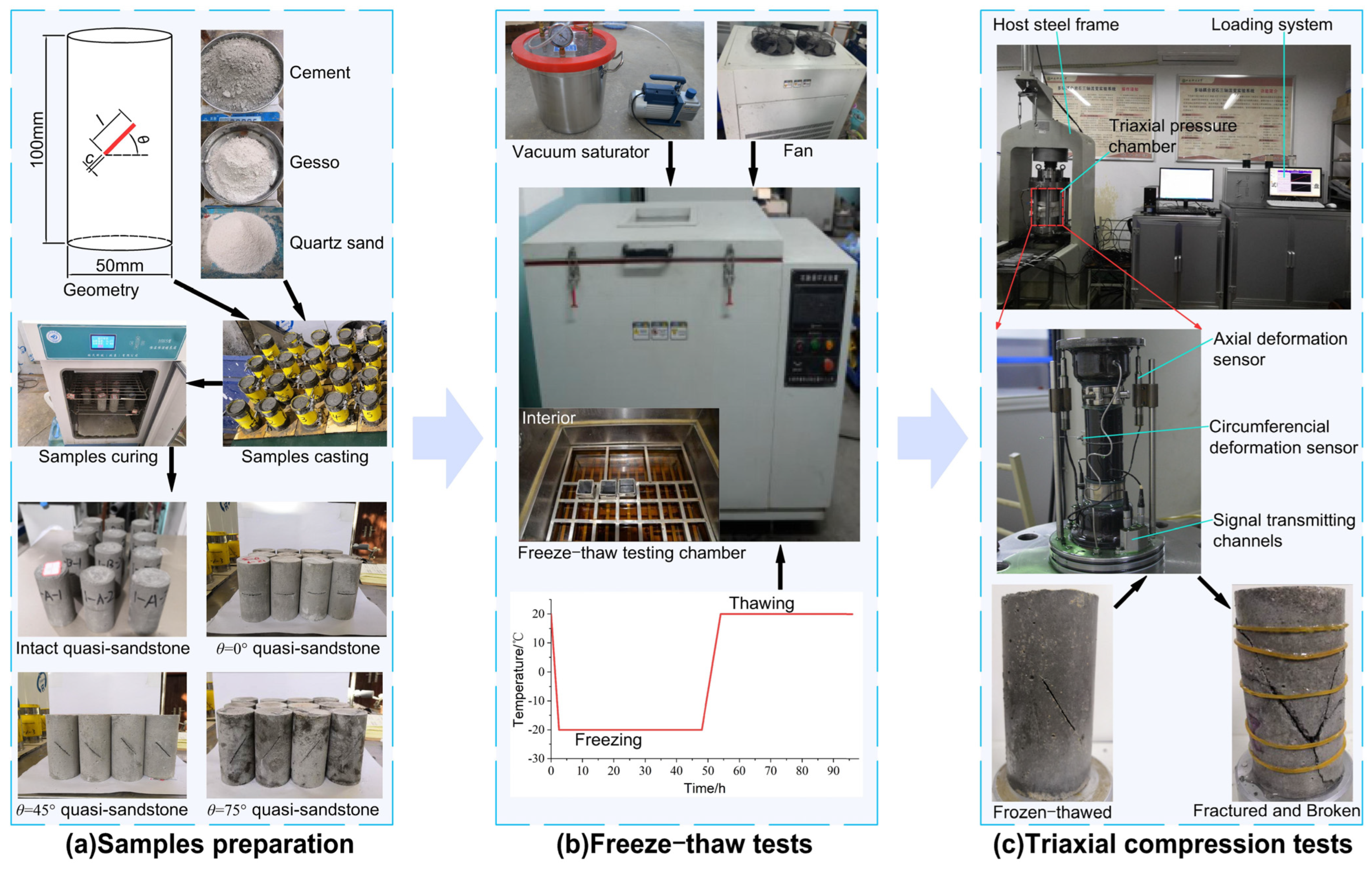
2.1. Quasi-Sandstone Materials

It is difficult to collect intact rock without the action of freeze–thaw load and to prefabricate through cracks. To ensure the uniformity of materials and reduce the influence of the dispersion of the sandstone in the Luohe Formation on the test results, quasi-sandstones were prepared. The aggregate was quartz sand and gesso. The cementing material was Portland cement with a strength grade of 32.5 MPa, and the auxiliary material was a cement early strength agent. Referring to the research by Shen et al. [24], based on the similarity law, a large number of orthogonal experiments with different mix proportions were conducted to determine the quality ratio of the quasi-sandstone materials gesso:cement:quartz sand:water = 1.0:6.5:2.5:3.0.

2.2. Preparation of Intact and Single-Fissured Samples

To compare and analyse the damage and fracture characteristics of sandstone with a single fissure at different angles after freezing–thawing and triaxial compression, complete standard cylindrical sandstone samples with prefabricated cracks of 50 × 100 mm were prepared. The prefabricated fissures were through microtensioned cracks with a width c of 1.5 mm and a length l of 20 mm. The dip angles θ of the prefissures were 0°, 45°, and 75°. As shown in Figure 1, the detailed steps of specimen preparation are as follows.
(1) The quartz sand, cement, gesso, and purified water, which were accurately weighed according to the quality, were poured into the container and stirred evenly.
(2) First, the insert was embedded in the fissured mold, and then the cement mortar was poured into the corresponding numbered mould, and the internal bubbles were eliminated by vibration to ensure the uniformity of the specimens; after the samples were solidified, the insert was pulled out to form a penetrating fissure.
(3) After a sample was demoulded, an HWS constant temperature and humidity curing chamber produced by Linmao Technology Co., Ltd. (Beijing, China) was used to maintain the cement mortar at 25 °C and 98% humidity.
(4) The upper and lower faces of the completely cured samples were smoothed by a rock mill to meet the flatness requirements.

2.3. Basic Physical and Mechanical Parameter Test

The original rock samples and quasi-sandstone samples after curing were compared and screened. First, the samples for which the flatness of the upper and lower ends was not qualified, and the overall or fissured size did not meet the requirements, were eliminated. Next, quality and ultrasonic wave velocity tests were performed to ensure the uniformity of the selected samples. The samples meeting the requirements were placed in an oven at 105 °C until the mass change was not more than 0.1% and then taken out in the drying dish. The quality of the samples was measured after natural cooling to room temperature. Then, as shown in Figure 1, the samples were placed in a vacuum forced saturation device, and the air pressure was kept at 0.1 MPa for continuous pumping for 6 h. The samples were then saturated in a container for 24 h. The porosity, density, and longitudinal wave penetration velocity of the ultrasonic waves under saturated conditions were measured after the surface moisture of the samples was removed. Finally, the samples were subjected to uniaxial loading experiments on a universal loading machine to obtain the basic physical and mechanical parameters of the Luohe Formation sandstones and quasi-sandstones, as shown in Table 1. The effective porosity of the quasi-sandstones was slightly larger than that of the original rock, increasing the damage caused by freezing–thawing. However, in general, the similar materials basically met the requirements of the similarity law. The test using quasi-sandstones can reflect the mechanical law of the freezing–thawing and loading of sandstones in the actual Luohe Formation.

2.4. Testing Scheme

In the actual project, the burial depth of sandstone in Luohe Formation is approximately 200 m, so 2 MPa was selected as the confining pressure in this test. As shown in Figure 1, the loading test was carried out using a rock thermo–hydro–mechanical–chemical multifield coupling triaxial compression test system developed jointly by the Wuhan Institute of Geomechanics, Chinese Academy of Sciences, and Xi’an University of Science and Technology. Twelve samples in each of groups B, C, and D were selected, and the 36 samples were subjected to a single freeze–thaw cycle test. The specific scheme is shown in Table 2. As shown in Figure 1, the samples were first saturated and then placed in a freeze–thaw testing chamber. The freezing temperatures were set to −10, −20 and −30 °C, respectively. After 48 h of freezing, the specimens were melted at 20 °C. Based on the temperature variation measured by Levin et al. [7], the melting time was set to 48 h. Finally, all samples of group A and groups B, C, and D after freezing–thawing were subjected to triaxial loading.

3. Fracture Characteristics

3.1. Damage Behaviour after Freezing–Thawing

Figure 2 is a damage diagram of quasi-sandstone after thawing for various freezing temperatures. It shows that the intact quasi-sandstone and the quasi-sandstone with different angle fissures have different degrees of surface spalling or crack propagation after thawing. There are two main types of frost-heaving fracture mode of the original fissure [52]: (i) Coplanar frost-heaving propagation cracks appear at the end of the prefabricated fissure, propagate along the direction of the original fissure for a certain distance, and gradually turn to the short side of the sample. These are called ‘coplanar propagation cracks’. (ii) The two sides of the middle of the prefabricated fissure produce a frost-heave propagation crack in an approximately horizontal direction, which is called a ‘horizontal propagation crack’.
The damage and fracture characteristics of samples after thawing at different freezing temperatures were significantly different. For a freezing temperature Tf = −10 °C, random flake spalling occurred on the surface and top of the intact quasi-sandstone samples after thawing, and the scale of spalling was small. The crack propagation laws caused by cracks with different dip angles were also different. When the fissure angle was 0°, small flake spalling occurred on the surfaces of the sample, and a horizontally extended microcrack (coplanar propagation crack) appeared along with the tip position of the prefabricated fissure. When the fissure angle was 45°, the flake spalling around the prefabricated fissure was large, and the spalling at the top was small. When the fissure angle was 75°, the flake spalling amount on the surface of the sample was less than that of the specimen with a fissure angle of 45°. The crack did not appear at the end of the prefabricated fissure, but near the top. This indicates that, for quasi-sandstone with fissure angles of 0°, 45°, and 75°, the localised damage effect caused by thawing at Tf = −10 °C decreases with the increase in fissure angle. The fracture characteristics of Tf = −20 °C and Tf = −30 °C quasi-sandstone after freezing–thawing were compared and analysed. With the decrease in freezing temperature, the amount of spalling at the top edge of quasi-sandstone samples increased gradually, and the number and penetration of new cracks initiated at the apex of the prefissure increased.
Because of the large difference in potential propagation paths, the freeze–thaw temperatures of crack propagation required for quasi-sandstone fissures with various angles also differ. When the fissure angle is 0°, the potential propagation path is 15 mm, and Tf = −10 °C thawing produces obvious frost-heaving cracks. When the fissure angle is 75°, the potential propagation path is 41 mm, so a freeze–thaw cycle at Tf = −30 °C is needed to generate frost-heaving cracks, which is consistent with the results obtained by the principle of ‘minimum resistance area’ proposed by Shen et al. [24].

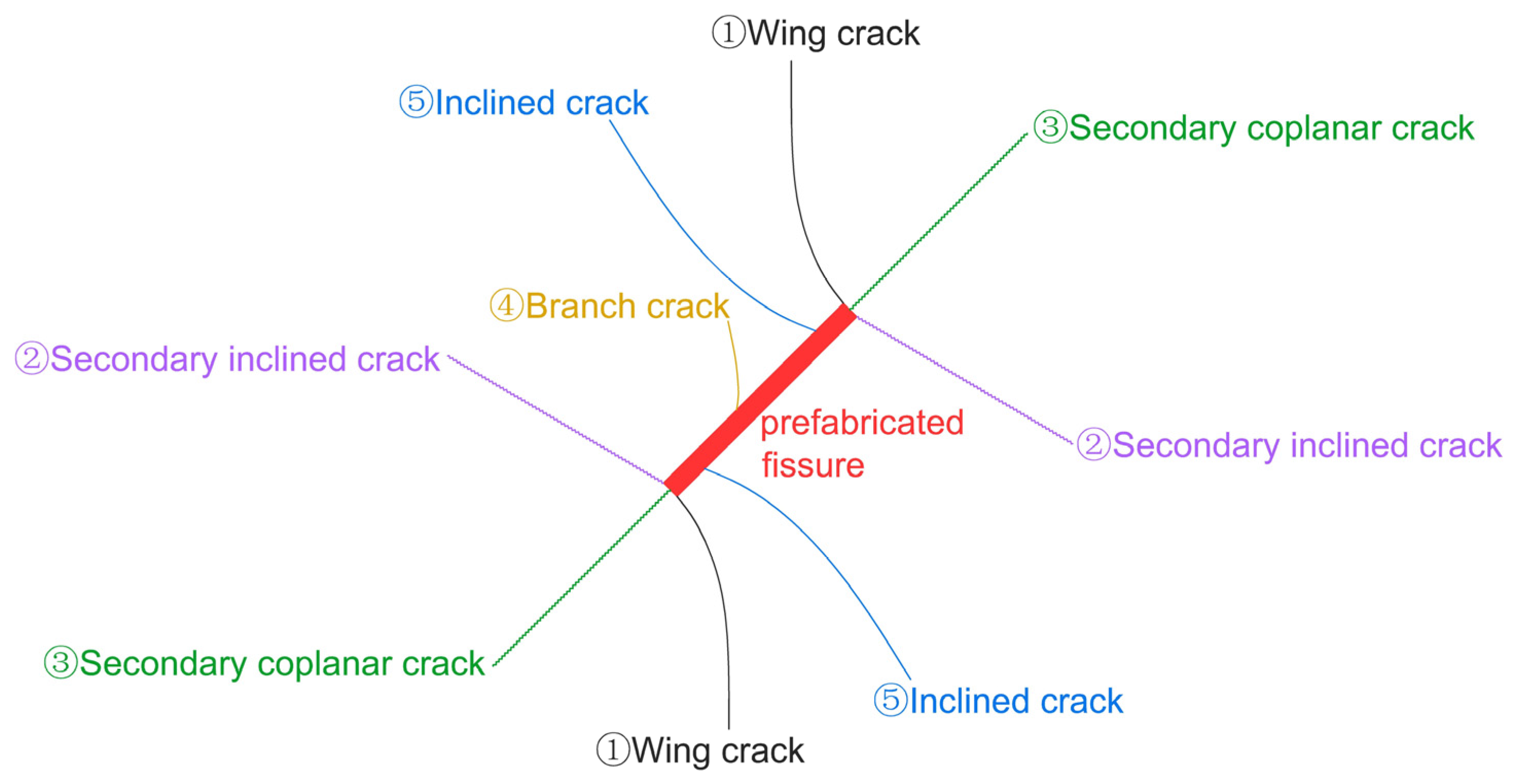
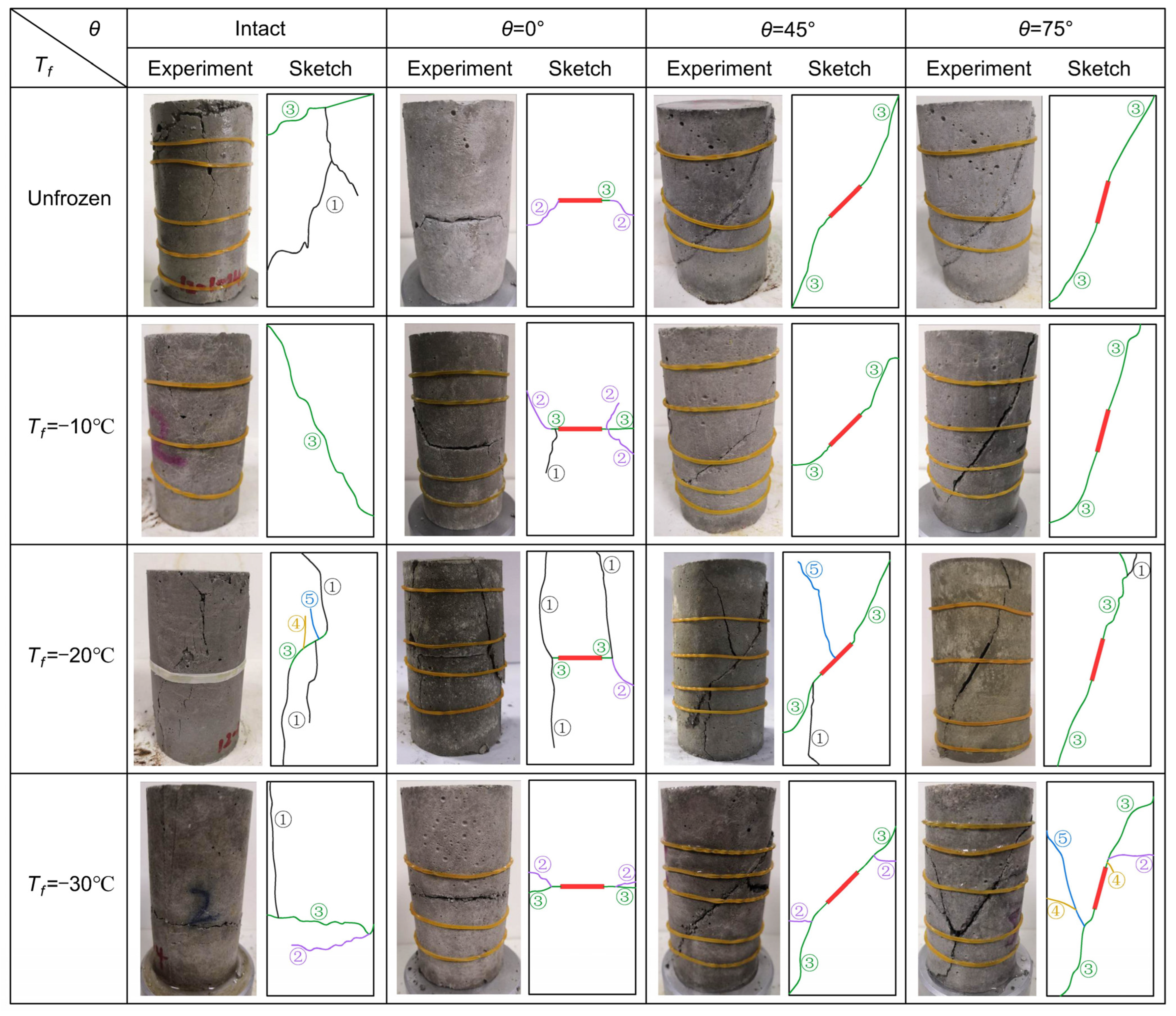
3.2. Fracture Characteristics after Freeze–Thaw and Triaxial Compression

According to Huang et al. [52], frost-heaving cracks have different effects on the fracture mode of quasi-sandstones with a single fissure at different angles under uniaxial compression. According to the research of Xiao et al. [53] on the crack coalescence of single-fissured rock, with the increase in ambient pressure, the failure mode of quasi-rock gradually becomes ductile, and the crack propagation in quasi-rock is more complicated. Single-fissured rock under triaxial compression mainly has three kinds of through fracture form [54]: tensile, shear and tensile–shear mixed failure. The main branch cracks at the prefissured apex of rock under triaxial compression are [55]: (1) wing crack, (2) secondary inclined crack, (3) secondary coplanar crack, (4) branch crack and (5) inclined crack, as shown in Figure 3. For the saturated macro-fissures in this experiment, the freeze–thaw cycle with a freezing temperature of −10 °C can drive the fissure tip to initiate new macro-frost-heaving cracks. It is necessary to study the influence of frost-heaving cracks on the fracture mode of triaxial compression.
Therefore, typical failure samples with a confining pressure of 2 MPa and freezing temperatures of unfrozen, −10, −20 and −30 °C, are selected for analysis, and the fracture failure diagram of quasi-sandstone with three kinds of single-fissured angles at four freezing temperatures is obtained, as shown in Figure 4. The intact rock sample shows tensile–shear failure under triaxial compression without freezing, and the single-fissured sample is a shear-slipped failure. Tensile cracks are mainly produced in rock samples without prefabricated fissures, and shear oblique cracks appear at the upper end. When θ = 0°, the fracture mode of the sample mainly presents as secondary inclined cracks (2) at both ends of the prefabricated fissure. When θ = 45°, the secondary coplanar crack (3) initiates at the apex of the prefissure, and its initiation direction is along the direction of the prefabricated crack. When it extends to a certain extent, the upper and lower cracks (3) deflect toward the orientation of the maximum main stress until the end of the sample. When θ = 75°, two secondary coplanar cracks (3) initiate at the apex of prefissure, and its initiation direction is the same as that of the prefabricated fissure. When it extends to a certain extent, the upper crack (3) deflects toward the orientation of the major principal stress until the end of the rock sample, and the lower crack (3) propagates tortuously along the orientation of the resultant force of the maximum main stress and the minimum main stress until reaching the lateral face of the sample.
When Tf = −10 °C, the 0° fissure specimen under triaxial compression is a tensile–shear mixed failure, and the other samples are all shear failure. There is only one shear oblique crack penetrating specimen in the intact quasi-sandstone. Because of the freeze–thaw effect, the number of secondary inclined cracks (2) along the prefissure tip of the quasi-sandstone with a fissure angle of 0° increases. When loaded, the prefissure is closed first, and then the fracture along the frost-heaving cracks at both ends is produced and finally sheared. For the quasi-sandstone with a 45° angle fissure, compared with the fracture mode without freezing, the difference is that the cracks (3) in the upper and lower parts extend along the coplanar direction of the prefabricated fissure, and then they extend in the orientation of the maximum main stress until the side edge of the sample. Frost-heaving cracks do not occur in the 75° inclination prefissured sample owing to freezing and thawing, so the final fracture mode is the same as that in the unfrozen state.
The failure diagram and failure sketch of quasi-sandstone samples with different angles of fissure after thawing at Tf = −20 °C reveal that the intact specimen and single-fissured specimens under triaxial compression all underwent tensile–shear mixed failure. There are three wing cracks (1), one branch crack (4), and one oblique crack (5) along the shear crack in the middle of the intact sample. When θ = 0°, there are three wing cracks (1) and one secondary inclined crack (2) at both ends of the prefabricated fissure. With the continuous decrease in freezing temperature, the local damage effect of frost-heaving force at the tip of the prefissure increases, but the horizontal coplanar frost-heaving crack has little effect on the crack coalesce–fracture mode of quasi-sandstone with a 0° angle prefissure. When θ = 45°, the main crack leading to final failure is the same as that at Tf = −10 °C because there is only coplanar propagation cracking, but there are two cracks: inclined (5) and wing (1). This is because, with the decrease in freezing temperature, the frost-heaving force generates a stress concentration at the tip of the prefissure to form new cracks, thereby weakening the mechanical properties of fissured quasi-sandstone. When θ = 75°, freezing–thawing does not produce macroscopic cracks. The secondary coplanar cracks (3) at both ends of the prefissure extend to a certain extent, deflect toward the orientation of the maximum main stress, and propagate to the end face, leading to the quasi-sandstone through fracture. There is also a wing crack (1) near the upper end face.
When Tf = −30 °C, under triaxial compression, the intact sample experienced a tensile–shear mixed failure, and the single-fissured specimen had a shear failure. In addition to a vertical wing crack (1), a secondary coplanar crack (3) with oblique section penetration also formed in the intact quasi-sandstone after thawing because of the large damage of the internal particles of the sample caused by the frost-heaving force during the freezing process at Tf = −30 °C. Then, the damage particles close to the transverse distribution under the action of deviatoric stress penetrate and form a fracture surface. The quasi-sandstone sample with a fissure dip angle of 0° after thawing developed a fracture cross section along the length direction of the prefissure under triaxial compression. This is because of the long secondary coplanar propagation cracks at the tip of the prefissure under the action of frost-heaving force. These cracks further develop and expand under the action of deviatoric stress. Finally, the main fracture surface is formed, leading to the instability and failure of the sample. After thawing, the failure mode of quasi-sandstone with a fissure dip angle of 45° is still a typical shear-slip failure, and the upper crack is the frost-heaving crack further expanding along the quasi-plane of the prefissure. Compared with Tf = −20 °C, the particles around the secondary coplanar cracks (3) are more broken, and there is no inclined crack (5) in the middle of the pre-fissure. Compared with the quasi-sandstone sample with a fissured dip angle of 75° and Tf = −20 °C, in addition to the two secondary coplanar cracks (3) forming the main sliding surface along the pre-fissure, there are also one secondary inclined crack (2), one inclined crack (5) and two branch cracks (4) at the end of the frost-heaving cracks. This shows that, with the decrease in the frozen temperature, the mechanical properties of the quasi-sandstone sample with a single fissure after thawing are weakened, and the block after loading is more broken.

4. Damage Constitutive Model and Damage Evolution Law

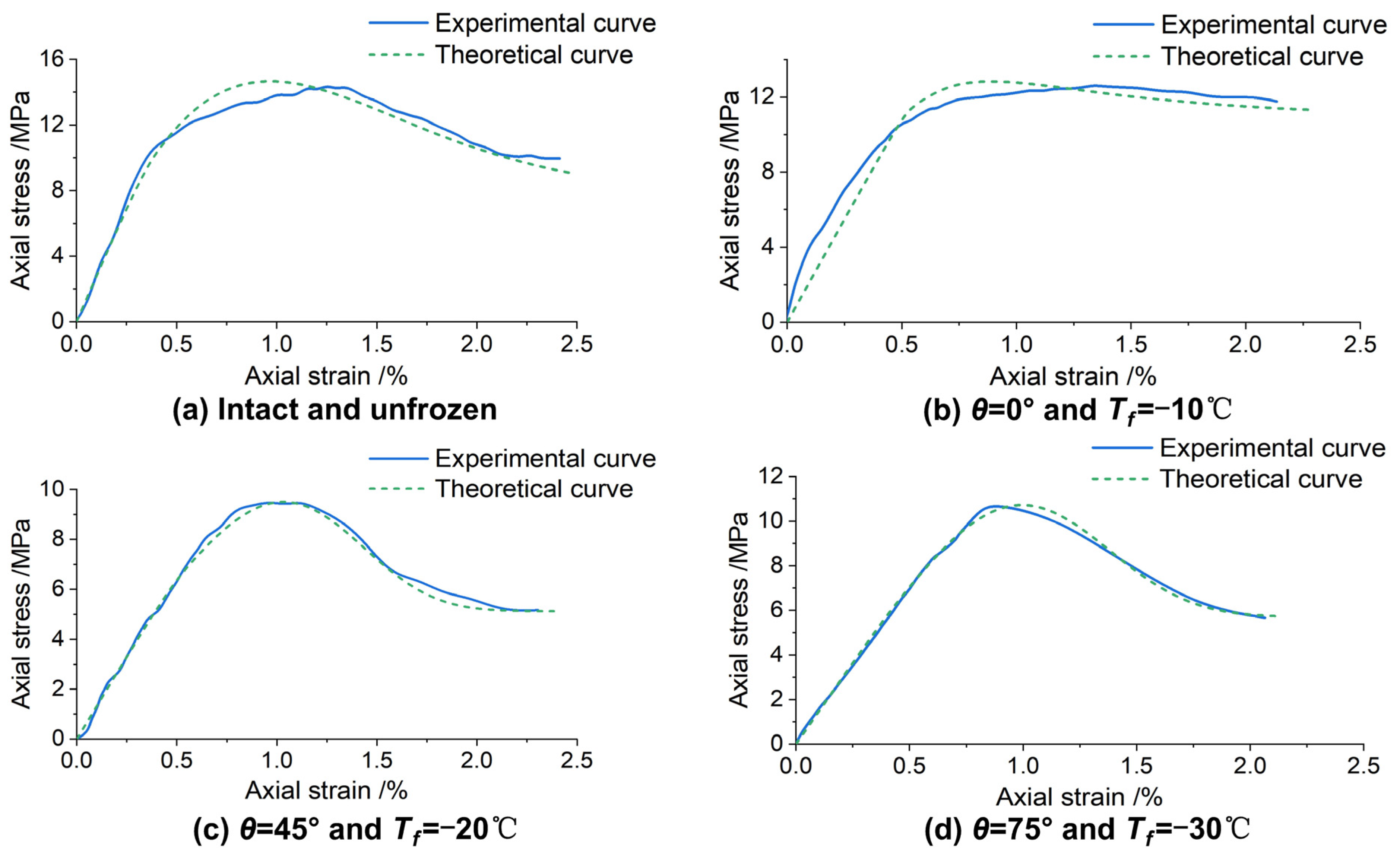
4.1. Constitutive Model of Single-Fissured Quasi-Sandstone Subjected to Freezing–Thawing and Load Considering Residual Strength

4.1.1. Establishment of Constitutive Equation

The recent damage constitutive model of single-fissured quasi-sandstone under freezing–thawing and static loading has difficulty in accurately reflecting the postpeak deformation characteristics. Therefore, based on the research by Zhang et al. [46,47], it is assumed that there are damage elements and nondamage elements in the single-fissured quasi-sandstone after freezing–thawing and triaxial compression and that the damage elements can also bear part of the axial stress (that is, the constant quasi-linear section after the stress–strain curve descends). The damaged part includes the fissured damage, freeze–thaw damage, damage from static loading, single-fissure and freeze–thaw coupling damage, single-fissure and load coupling damage, freeze–thaw and static loading coupling damage, and the coupling damage of the three. Assuming that the damaged part can also bear residual stress, a constitutive model of single-fissured quasi-sandstone subjected to freezing–thawing and static load considering residual strength was established.
When the single-fissured quasi-sandstone is frozen–thawed and loaded, in the direction of the principal stress σ 1 , assuming that the undamaged part of the single-fissured quasi-sandstone bears effective stress σ 1 * , the corresponding infinitesimal area is A1. The damaged part is subjected to residual stress σ r and the corresponding area is Ar. Then,
σ 1 A = σ 1 * A 1 + σ r A r
A = A 1 + A r
In short, the ultimate damage of the quasi-sandstone is determined by the single fissure, freezing–thawing and static loading. Therefore, the general damage variable Dg is defined as
D g = A r A
Based on Equations (1)–(3),
σ 1 = σ 1 * ( 1 D g )   +   σ r D g
The constitutive relation of the undamaged part follows the generalised Hooke’s law.
σ 1 * = E 0 ε 1 * + μ f t ( σ 2 * + σ 3 * )
where E0 is the static elastic modulus of intact quasi-sandstone at a normal temperature, ε 1 * is the effective axial strain of the undamaged elements of the single-fissured quasi-sandstone, and μ f t is the Poisson ratio of single-fissured quasi-sandstone after freezing–thawing.
According to the coordination relationship of quasi-sandstone deformation,
ε 1 * = ε 1
Under the conventional state of three-dimensional stress, the quasi-sandstone is subjected to increased axial stress until failure under the confining pressure. Therefore, the lateral residual strength can be ignored, that is, the lateral load is resisted by the undamaged part.
σ 2 * = σ 2 , σ 3 * = σ 3
Substituting Equations (6) and (7) into Equation (5) results in
σ 1 * = E 0 ε 1 + μ f t ( σ 2 + σ 3 )
The intact quasi-sandstone is cut by the structural plane to form macroscopic defects, which are distributed in the quasi-sandstone in different forms, resulting in fissured damage of the quasi-sandstone. Furthermore, its strength and deformation characteristics have a strong response. Therefore, the static elastic modulus can be used to measure the fissure damage of single-fissured quasi-sandstone. The fissure damage variable Df is defined as
D f = 1 E f E 0
where Ef is the static elastic modulus of quasi-sandstone with a single fissure at different angles.
Single-fissured quasi-sandstone shows the heterogeneity of the mesostructure, which gives the strength of micro-element within the material a probability distribution. During the loading process, the internal microflaws continue to be generated, develop, and evolve into new macroflaws, and the failure of micro-units shows randomness. Assuming that the strength of micro-units follows a Weibull distribution, the loading damage variable Dl is
D l = 0 F * P ( F * ) d F = 1 e x p [ ( F * F 0 ) m ]
where F* is the statistical distribution variable of infinitesimal strength, and m and F0 are undetermined parameters in the Weibull distribution.
Based on the static elastic modulus of intact quasi-sandstone at a normal temperature, the freeze–thaw damage variable Dt can be defined as
D t = 1 E t E 0
where t is the minimum temperature (−10, −20, and −30 °C) in a freeze–thaw cycle, and Et is the static elastic modulus of intact quasi-sandstone after thawing at the lowest frozen temperature t.
Here, Dg is defined as the general damage variable of single-fissured quasi-sandstone under freeze–thaw and load, which characterises the coupling effect of the initial fissure damage Df, freeze–thaw damage Dt and load damage Dl. According to Figure 5, the expression of Dg indicated by the total area is
D g = D f + D t + D l D f D t D f D l D t D l + D f D t D l
From Equation (12), it can be perceived that the fissure damage variable reflects a macroscopic single fissure that increases the total damage to the quasi-sandstone, the freeze–thaw damage variable reflects freeze–thaw action that increases the total damage to the quasi-sandstone, and the loading damage variable reflects the continuous damage deterioration trend of quasi-sandstone under static loading. The respective effects and coupling effects of the three types of damage aggravate the total damage, and the coupling term is expressed by DfDtDl. However, the coupling effect of each two damage types can reduce the total damage, and the coupling term is expressed by DfDt, DfDl, and DtDl.
By substituting Equations (9)–(11) into Equation (12), the total damage expression of a single-fissured quasi-sandstone under freezing–thawing and triaxial compression can be obtained
D g = 1 E f E t E 0 2 e x p [ ( F * F 0 ) m ]
By substituting Equations (8) and (13) into Equation (4), the damage constitutive equation of single-fissured quasi-sandstone under freezing–thawing and triaxial compression considering residual stress can be obtained
σ 1 = σ r + ( E 0 ε 1 σ r + 2 μ f t σ 3 ) E f E t E 0 2 e x p [ ( F * F 0 ) m ]
Based on the Drucker–Prager criterion, F* can be written as
F * = α I * + J 2 *
where α is a constant related to the angle φ of internal friction of quasi-sandstone, I* is the first invariant of the effective stress, and J 2 * is the second invariant of the effective stress deviator. Their expressions are:
α = 2 s i n f 3 ( 3 s i n f )
I * = σ 1 * + σ 2 * + σ 3 *
J 2 * = 1 6 [ ( σ 1 * σ 2 * ) 2 +   ( σ 2 * σ 3 * ) 2 +   ( σ 3 * σ 1 * ) 2 ]
where σ 1 * is the axial effective stress; σ 2 * , σ 3 * is the lateral effective stress; and σ i * = σ i / ( 1 D g ) , (i = 1, 2, 3).
According to Equations (15)–(18), the expression of F* in Equation (14) can be obtained
F * = ( α   +   3 3 ) E 0 ε 1   +   ( 2 α   +   2 3 3 ) μ f t σ 3   +   ( 2 α     3 3 ) σ 3

4.1.2. Determining Model Parameters

The model parameter is an important indicator of the damage evolution characteristics of materials, and it is essential for reflecting the nonlinear deformation of single-fissured quasi-sandstone. The undetermined parameters must be determined according to the basic mechanical variables of single-fissured quasi-sandstone. Using the extremum condition at the peak of the model curve, the theoretical expressions of the parameters m and F0 of the constitutive model of single-fissured quasi-sandstone subjected to static loading after freezing–thawing can be obtained. The two extremum conditions of the curve σ 1 ε 1 at the peak point are
ε 1 = ε c , σ 1 = σ c ; ② ε 1 = ε c , σ 1 ε 1 = 0
From the extremum condition 1 and Equation (14), one can obtained
( F * F 0 ) m = l n [ E f E t ( E 0 ε c     σ r + 2 μ f t σ 3 ) E 0 2 ( σ c     σ r ) ]
According to extremum conditions 2 and Equations (14) and (19),
( F * F 0 ) m = ( α   +   3 3 ) E 0 ε c + ( 2 α   +   2 3 3 ) μ f t σ 3   +   ( 2 α 3 3 ) σ 3 ( α   +   3 3 ) m ( E 0 ε c     σ r + 2 μ f t σ 3 >)
By combining Equations (20) and (21), one can obtain the expressions of undetermined parameters m and F0
m = ( α   +   3 3 ) E 0 ε c   +   ( 2 α   +   2 3 3 ) μ f t σ 3   +   ( 2 α 3 3 ) σ 3 ( α   +   3 3 ) >( E 0 ε c σ r   +   2 μ f t σ 3 ) l n [ E f E t ( E 0 ε c σ r   +   2 μ f t σ 3 ) E 0 2 ( σ c σ r ) ]
F 0 = { ( α   +   3 3 ) E 0 ε c   +   ( 2 α   +   2 3 3 ) μ f t σ 3   +   ( 2 α 3 3 ) σ 3 } × { 1 l n [ E f E t ( E 0 ε c σ r   +   2 μ f t σ 3 ) E 0 2 ( σ c σ r ) ] } 1 m
By substituting Equations (22) and (23) into Equations (13) and (14), a complete damage evolution model and constitutive equation of single-fissured quasi-sandstone subjected to static loading after freezing–thawing can be obtained. Equation (13) shows that, when the axial strain, fissure angle, and freeze–thaw temperature of quasi-sandstone change, the evolution of the general damage rate is
D g = ( 1 D f ) ( 1 D t ) D l ε 1   +   ( 1 D l ) ( 1 D t ) D f f   +   ( 1 D f ) ( 1 D l ) D t t
Equation (24) indicates that the general damage of quasi-sandstone changes with the increase or decrease in axial strain, fissure angle, and frozen temperature, and the damage mechanical behaviours of single-fissured quasi-sandstone are coupled and influenced by the three changes.

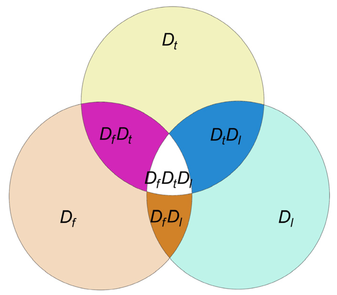
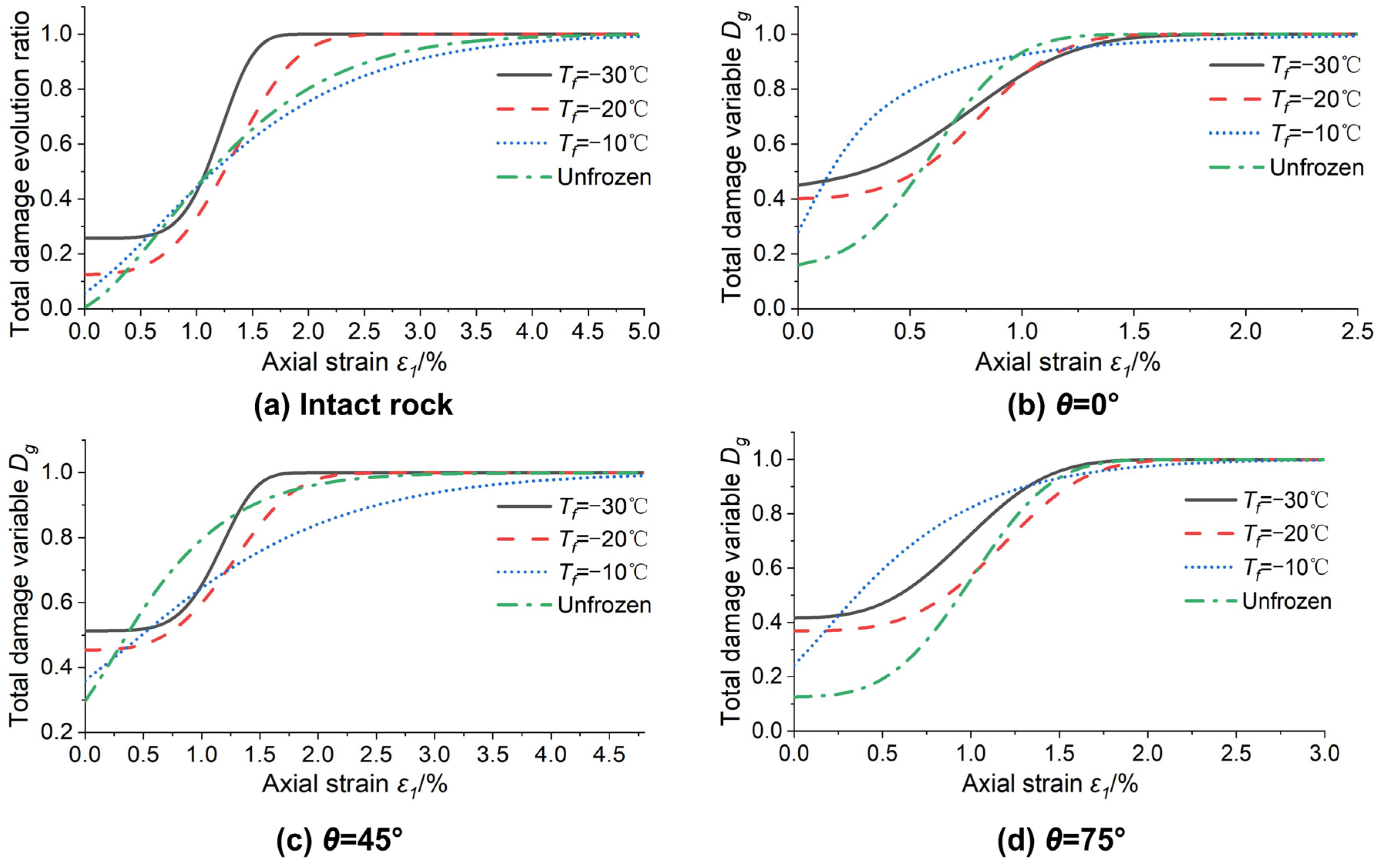
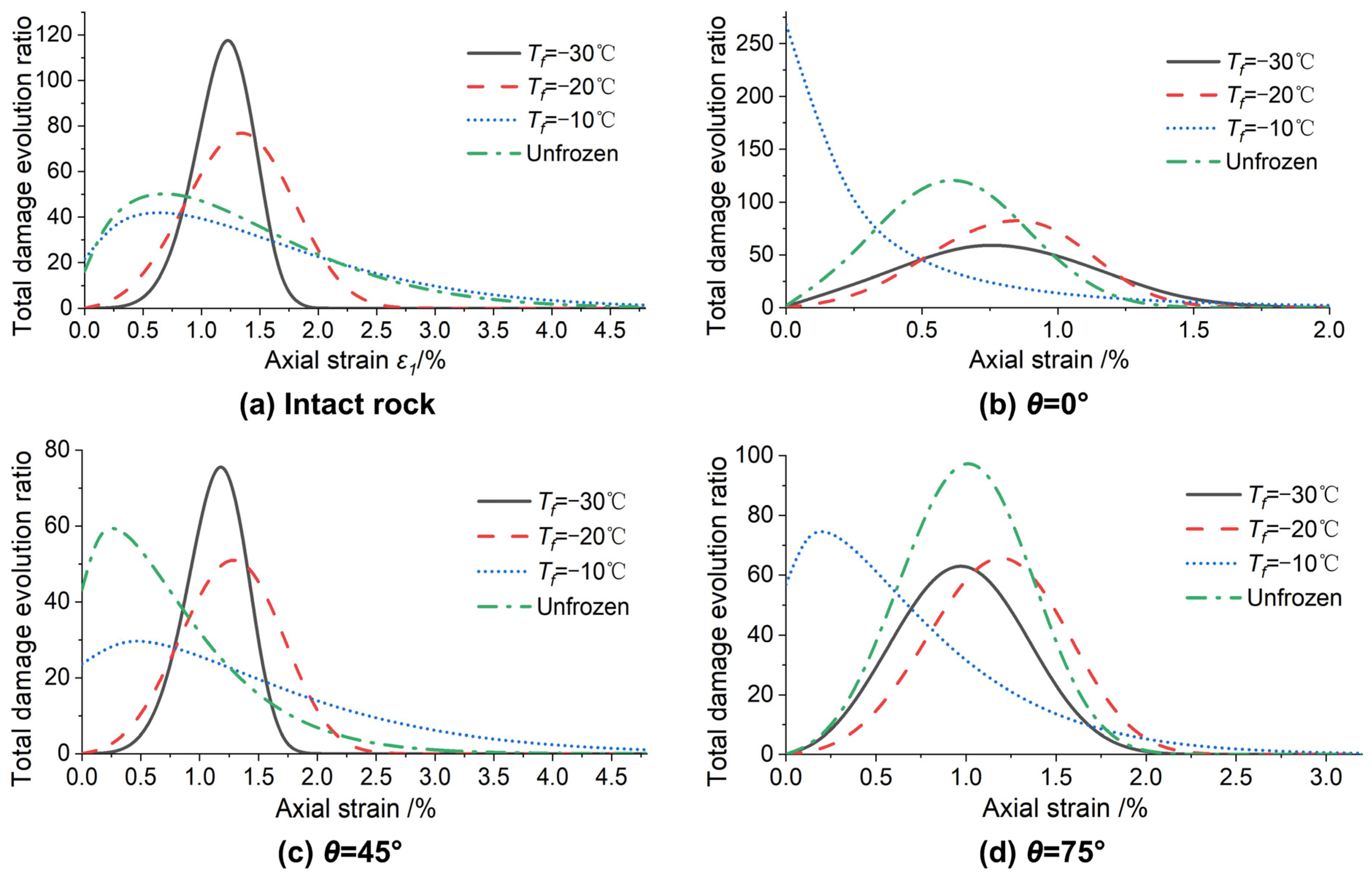
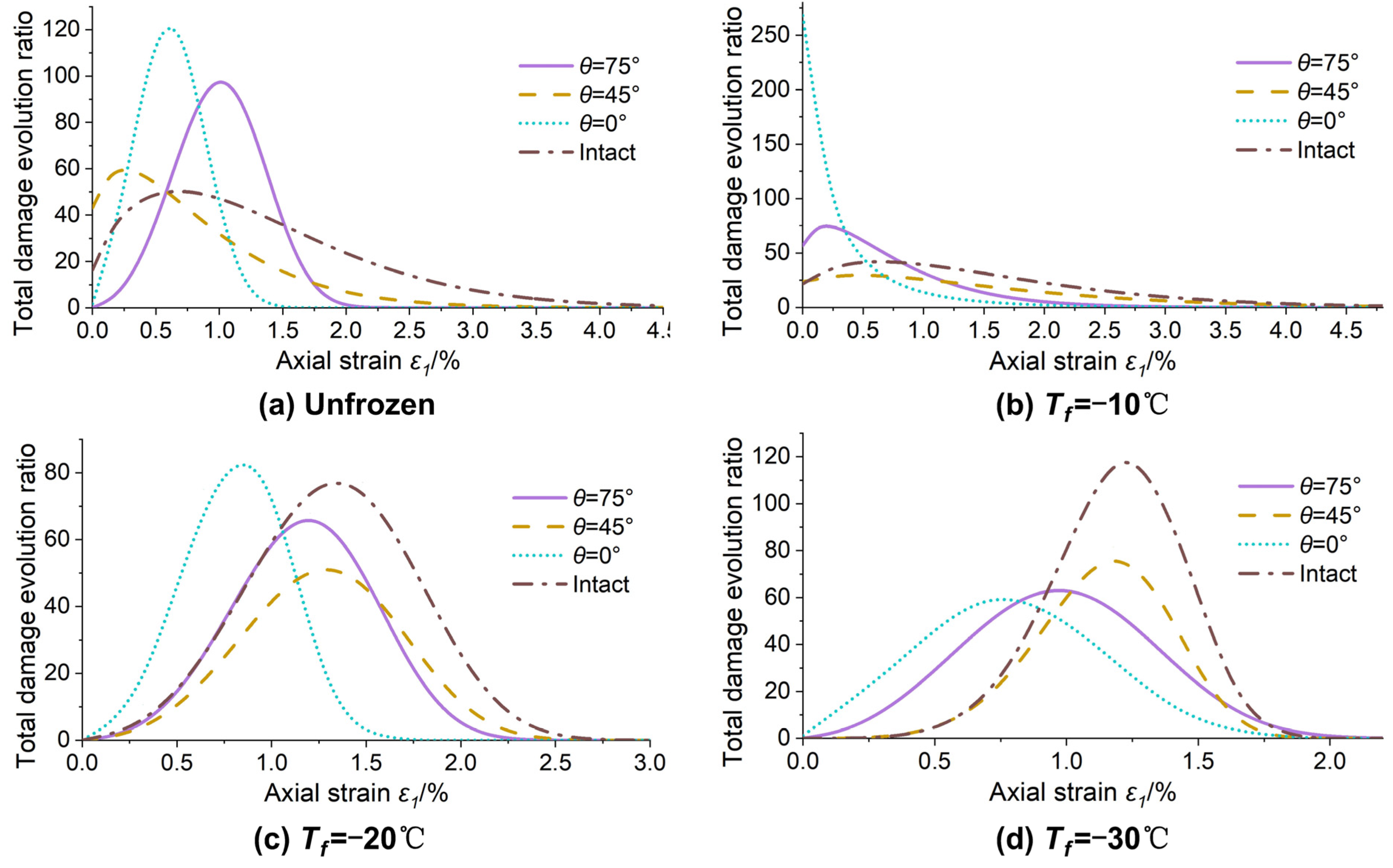
4.2. Evolution Law of Loading Damage of Single-Fissured Quasi-Sandstone after Freezing–Thawing

In the triaxial compression test, repeatability tests of three samples were conducted under each condition. To reduce the test error, first, the suspicious data or individual abnormal values are abandoned, and then the average value of each mechanical parameter is calculated. The final summary is shown in Table 3. According to Table 3 and Equation (13), the theoretical curves of total damage evolution of quasi-sandstone with four kinds of single-fissured angles subjected to static loading after freezing–thawing can be calculated, as shown in Figure 6.
Figure 6 shows that the initial damage of quasi-sandstone samples gradually increases with the decrease in freezing temperature. For the freeze–thaw samples with Tf = −20 °C and Tf = −30 °C, with the gradual increase in axial strain, the cumulative damage Dg increases slowly first, then rises sharply, then increases slowly, and finally reaches 1 when the quasi-sandstone sample is unstable and fails. For the unfrozen sample and that with Tf = −10 °C, the cumulative damage Dg increases sharply in the early stage, but the subsequent growth slows, especially for the samples with Tf = −10 °C.
Similarly, the total damage evolution curves of single-fissured quasi-sandstone subjected to static loading after freezing–thawing at four temperatures can be obtained (Figure 7). In terms of the initial damage, the order from small to large is as follows: intact quasi-sandstone < θ = 75° < θ = 0° < θ = 45°. However, according to the order in which the cumulative damage first reaches 1 is θ = 0°, 75°, 45°, and intact quasi-sandstone. In terms of the shape of the curve, the intact quasi-sandstone is similar to θ = 45°, and θ = 0° is more similar to θ = 75°. According to a study by Zhang et al. [46], the S-shaped damage evolution curve corresponds to each stage of triaxial compression of quasi-sandstone. (i) The stage of fissure compaction and elastic deformation corresponds to the quasi-horizontal section at the beginning of the damage–strain curve under loading, and the damage variable is almost unchanged. (ii) In the plastic deformation stage, the damage variable increases rapidly, corresponding to the concave section of the damage–strain curve. (iii) In the strain-softening stage, corresponding to the convex section of the damage–strain curve, the slope of the curve gradually decreases. (iv) In the residual deformation stage, the quasi-sandstone damage variable remains 1.
However, Figure 7 shows that only when Tf = −20 °C and Tf = −30 °C, the damage evolution curve of the quasi-sandstone is more like an S shape, which can be explained by the results of Bai, Zhao, and Liu et al. [42,56,57]. When the temperature of the quasi-sandstone is lower than the effective frozen temperature, the water in the quasi-sandstone fissures freezes, and the frost-heaving force significantly increases, so that the axial strain of quasi-sandstone is reduced and the brittle failure characteristics are more obvious. Thus, Tf = −10 °C can be regarded as the mutation point of freeze–thaw damage in quasi-sandstone.
According to Table 3 and Equation (24), the general damage changing rate curves of quasi-sandstone with four kinds of single-fissure angle subjected to static loading after freezing–thawing can be obtained, as shown in Figure 8.
Figure 8 shows that, with the increase in axial strain, Tf = −10 °C, unfrozen, Tf = −30 °C and Tf = −20 °C successively reach the peak of the damage change rate. The damage evolution curves of Tf = −20 °C and Tf = −30 °C show symmetrical distribution characteristics for the axial strain, whose law resembles a normal distribution. The curve of unfrozen and Tf = −10 °C shows a partial normal distribution truncated by the longitudinal axis.
Similarly, according to Table 3 and Equation (24), the general damage changing rate curves of quasi-sandstone with a single fissure subjected to static loading after freezing–thawing at four temperatures can be obtained (Figure 9). For the extreme value of curves, θ = 0°, 75°, 45°, and intact quasi-sandstone appear in turn with increasing axial strain.
Figure 10 is based on the results of the freeze–thaw and static loading tests shown in Table 3. Using Equations (14), (22), and (23), the theoretical curves of the total damage constitutive model of quasi-sandstone with four single-fissured angles subjected to static loading after freezing–thawing at different temperatures were calculated, and they are compared in Figure 10 with the experimental curves.
Figure 10 indicates that the theoretical curve is consistent with the experimental curve, which can better reflect the stress–strain behaviour of quasi-sandstone under different freezing temperatures and fissured angles, especially the residual stress in the later stage, thus verifying the rationality of the constitutive model.

5. Discussions

Table 3, Figure 6 and Figure 7 shows that the mechanical properties of quasi-sandstone samples with single fissure at 45° after freezing and thawing are the worst, and the mechanical properties of samples after thawing at −30 °C are the worst. In the actual design of artificial freezing shaft, the worst situation should be considered in combination with the fissure distribution of surrounding rock and the minimum freezing temperature. The future research direction can be the rock bridge failure law of frozen–thawed multi-fissured rock. Based on the research of Levin et al. [7], we find that if the fissure is still filled with ice when the wellbore surrounding rock is frozen, it is difficult to inject grouting into the rock fissure at this time. Only when the surrounding rock in a certain range behind the wall is naturally thawed can grouting be carried out. Grouting during thawing of frozen wall cannot be effective immediately. The final setting time of cement slurry is generally about 28 h, and it takes more than 10 days to achieve sufficient compressive strength [58]. Therefore, during the period when the surrounding rock is melted without grouting or the grouting is basically without strength, the fissured rock is mainly subjected to stress by itself, which is easy to cause surrounding rock damage and water gushing accidents [17]. It is indeed necessary to study the mechanical properties and fracture characteristics of the fissured rock after freezing and thawing and simulate the extreme conditions encountered in the project, which can provide reference for the design of wellbore and the design of post-wall grouting. For example, considering the strength of a rock mass after freezing and thawing damage is more accurate for the design. The seepage and grouting effect of surrounding rock after freezing and thawing will be our future research direction.
In this research, we only conducted a comparative analysis of the stress–strain curve of the constitutive model and the test. In fact, numerical simulation of Particle Flow Code [59,60] or large-scale engineering [45] can be also conducted. Considering to translate discrete fracture network to equivalent continuum models has been studied [61,62,63,64], and considering the freeze–thaw damage in this model further is the focus of our research direction.

6. Conclusions

By prefabricating a single fissure with different angles in quasi-sandstone samples, single freeze–thaw tests and triaxial compression tests after thawing were conducted in a saturated state—unfrozen and with freezing temperatures of −10, −20 and −30 °C. The effects of the freezing temperature and fissure angle on the crack propagation process caused by frost heave were investigated, as well as the fracture failure characteristics and the damage evolution law of quasi-sandstone samples. The following conclusions were drawn.
(1) The initiation and propagation of frost-heaving cracks in a fissured rock mass are mainly caused by the frost-heaving force of the prefissures, and the frost-heaving force of the prefissures increases with the decrease in freezing temperature. The greater the inclination angle of the fissure, the greater the absolute value of the freezing temperature necessary to produce a frost heave crack.
(2) When the fissure angles are 45° and 75°, the fracture failure of the quasi-sandstone mass occurs along the frost-heaving cracks. The path of the frost-heaving cracks reduces the triaxial compressive strength of the single-fissured quasi-sandstone, and the frost-heaving cracks at a 0° angle do not necessarily change the fracture failure mode of quasi-sandstone.
(3) It is assumed that there are damage elements and nondamage elements in the single-fissured quasi-sandstone after freezing–thawing and triaxial compression, and the damage elements can also bear part of the axial stress. Based on the distribution theory of the micro-element strength and static elastic modulus of quasi-sandstone, a damage constitutive model of rock considering the effects of a single fissure, freeze–thaw temperature, confining pressure, and residual stress was established and verified experimentally.
(4) An S-shaped damage evolution curve corresponds to each stage of the triaxial compression of quasi-sandstone. With the decrease in freezing temperature, the strength of the quasi-sandstone after thawing decreases, and its brittleness characteristics strengthen.

Author Contributions

Conceptualization, Y.X.; Data curation, T.C.; Formal analysis, Y.X. and T.C.; Funding acquisition, J.R.; Investigation, T.C. and X.C.; Methodology, Y.X.; Project administration, J.R.; Resources, M.Y.; Supervision, J.R.; Validation, Y.X. and T.C.; Visualization, Y.X.; Writing–review and editing, T.C. and M.Y. All authors have read and agreed to the published version of the manuscript.

Funding

This research was supported by the National Natural Science Foundation of China (Grant No. 11872299, Grant No. 12072259) and the Natural Science Foundation of Shaanxi Province (Grant No. 2019JLP-01).

Institutional Review Board Statement

Not applicable.

Informed Consent Statement

Not applicable.

Data Availability Statement

The data used to support the findings of this study are available from the corresponding author upon request.

Conflicts of Interest

The authors declare no conflict of interest.

References

  1. Cai, H.B.; Yao, F.X.; Hong, R.B.; Lin, J.; Zeng, K. Multi-loop pipe freezing optimization of deep shaft considering seepage effect. Arab. J. Geosci. 2022, 15, 153. [Google Scholar] [CrossRef]
  2. Ren, J.X.; Sun, J.L.; Zhang, K.; Wang, J.; Wang, D.X. Mechanical properties and temperature field of inclined frozen wall in water-rich sand stratum. Rock Soil Mech. 2017, 38, 1405–1412. [Google Scholar]
  3. Alzoubi, M.A.; Xu, M.H.; Hassani, F.P.; Poncet, S.; Sasmito, A.P. Artificial ground freezing: A review of thermal and hydraulic aspects. Tunn. Undergr. Space Technol. 2020, 104, 103534. [Google Scholar] [CrossRef]
  4. Kodama, J.; Goto, T.; Fujii, Y.; Hagan, P. The effects of water content, temperature and loading rate on strength and failure process of frozen rocks. Int. J. Rock Mech. Min. Sci. 2013, 62, 1–13. [Google Scholar] [CrossRef]
  5. Liu, B.; Sun, Y.D.; Wang, J.; Zhang, G. Characteristic analysis of crack initiation and crack damage stress of sandstone and mudstone under low-temperature condition. J. Cold Reg. Eng. 2020, 34, 04020020. [Google Scholar] [CrossRef]
  6. Wang, P.S.; Zhou, G.Q. Frost-heaving pressure in geotechnical engineering materials during freezing process. Int. J. Min. Sci. Technol. 2018, 28, 287–296. [Google Scholar] [CrossRef]
  7. Levin, L.; Golovatyi, I.; Zaitsev, A.; Pugin, A.; Semin, M. Thermal monitoring of frozen wall thawing after artificial ground freezing: Case study of Petrikov Potash Mine. Tunn. Undergr. Space Technol. 2021, 107, 103685. [Google Scholar] [CrossRef]
  8. Sun, J.L.; Chen, X.Z.; Qiu, M.M.; Cao, X.Y.; Chen, S.J. Physical model test of artificial freezing-inclined shaft. Adv. Civ. Eng. 2021, 2021, 6640722. [Google Scholar] [CrossRef]
  9. Wu, T.; Zhou, X.M.; Zhang, L.G.; Zhang, X.J.; He, X.N. Theory and technology of real-time temperature field monitoring of vertical shaft frozen wall under high-velocity groundwater conditions. Cold Reg. Sci. Technol. 2021, 189, 103337. [Google Scholar] [CrossRef]
  10. Lin, H.; Lei, D.X.; Zhang, C.S.; Wang, Y.X.; Zhao, Y.L. Deterioration of non-persistent rock joints: A focus on impact of freeze–thaw cycles. Int. J. Rock Mech. Min. Sci. 2020, 135, 104515. [Google Scholar] [CrossRef]
  11. Jia, H.L.; Ding, S.; Wang, Y.; Zi, F.; Sun, Q.; Yang, G.S. An NMR-based investigation of pore water freezing process in sandstone. Cold Reg. Sci. Technol. 2019, 168, 102893. [Google Scholar] [CrossRef]
  12. Liu, B.; Ma, Y.J.; Liu, N.; Han, Y.H.; Li, D.Y.; Deng, H.L. Investigation of pore structure changes in Mesozoic water-rich sandstone induced by freeze-thaw process under different confining pressures using digital rock technology. Cold Reg. Sci. Technol. 2019, 161, 137–149. [Google Scholar] [CrossRef]
  13. Zhou, X.P.; Niu, Y.; Zhang, J.Z.; Shen, X.C.; Zheng, Y.; Berto, F. Experimental study on effects of freeze-thaw fatigue damage on the cracking behaviors of sandstone containing two unparallel fissures. Fatigue Fract Eng. Mater. Struct. 2019, 42, 1322–1340. [Google Scholar] [CrossRef]
  14. Zhang, G.Z.; Chen, G.Q.; Xu, Z.X.; Yang, Y.; Lin, Z.H. Crack failure characteristics of different rocks under the action of frost heaving of fissure water. Front. Earth Sci. 2020, 8, 13. [Google Scholar] [CrossRef]
  15. Maji, V.; Murton, J.B. Experimental observations and statistical modeling of crack propagation dynamics in limestone by acoustic emission analysis during freezing and thawing. J. Geophys. Res. Earth Surf. 2021, 126, e2021JF006127. [Google Scholar] [CrossRef]
  16. Wang, T.T.; Tang, C.A.; Tang, S.B.; Bao, C.Y.; Li, Y.; Fan, N. The mechanism of crack propagation during frost heave damage in fractured rock mass at low temperature. Arab. J. Geosci. 2021, 14, 1882. [Google Scholar] [CrossRef]
  17. Han, C.H.; Xu, J.G.; Zhang, W.J.; Wei, J.C.; Yang, F.; Yin, H.Y.; Xie, D.L. Assessment and grouting of water inrush induced by shaft-freezing holes in the Yingpanhao Coal Mine, Inner Mongolia, China. Mine Water Environ. 2022, 41, 16–29. [Google Scholar] [CrossRef]
  18. Chen, L.; Wu, P.; Chen, Y.; Zhang, W. Experimental study on physical-mechanical properties and fracture behaviors of saturated yellow sandstone considering coupling effect of freeze-thaw and specimen inclination. Sustainability 2020, 12, 1029. [Google Scholar] [CrossRef] [Green Version]
  19. Wang, Y.; Gao, S.H.; Li, C.H.; Han, J.Q. Energy dissipation and damage evolution for dynamic fracture of marble subjected to freeze-thaw and multiple level compressive fatigue loading. Int. J. Fatigue 2020, 142, 105927. [Google Scholar] [CrossRef]
  20. Yahaghi, J.; Liu, H.Y.; Chan, A.; Fukuda, D. Experimental and numerical studies on failure behaviours of sandstones subject to freeze-thaw cycles. Transp. Geotech. 2021, 31, 100655. [Google Scholar] [CrossRef]
  21. Liu, Y.Z.; Cai, Y.T.; Huang, S.B.; Guo, Y.L.; Liu, G.F. Effect of water saturation on uniaxial compressive strength and damage degree of clay-bearing sandstone under freeze-thaw. Bull. Eng. Geol. Environ. 2019, 79, 2021–2036. [Google Scholar] [CrossRef]
  22. Che, Y.X.; Song, Y.J.; Ren, J.X.; Chen, J.X.; Guo, X.X.; Tan, H.; Hu, M. Creep characteristics of different saturated states of red sandstone after freeze-thaw cycles. Geofluids 2021, 2021, 13. [Google Scholar] [CrossRef]
  23. Niu, Y.; Zhou, X.P.; Zhang, J.Z.; Qian, Q.H. Experimental study on crack coalescence behavior of double unparallel fissure-contained sandstone specimens subjected to freeze-thaw cycles under uniaxial compression. Cold Reg. Sci. Technol. 2019, 158, 166–181. [Google Scholar] [CrossRef]
  24. Shen, Y.J.; Yang, H.W.; Jin, L.; Zhang, H.; Yang, G.S.; Zhang, J.Y. Fatigue deformation and energy change of single-joint sandstone after freeze-thaw cycles and cyclic loadings. Front. Earth Sci. 2019, 7, 333. [Google Scholar] [CrossRef] [Green Version]
  25. Cao, R.H.; Wang, C.S.; Yao, R.B.; Hu, T.; Lei, D.X.; Lin, H.; Zhao, Y.L. Effects of cyclic freeze-thaw treatments on the fracture characteristics of sandstone under different fracture modes: Laboratory testing. Theor. Appl. Fract. Mech. 2020, 109, 102738. [Google Scholar] [CrossRef]
  26. Wang, Y.; Li, C.H.; Liu, H.; Han, J.Q. Fracture failure analysis of freeze–thawed granite containing natural fracture under uniaxial multi-level cyclic loads. Theor. Appl. Fract. Mech. 2020, 110, 102782. [Google Scholar] [CrossRef]
  27. Ke, B.; Zhang, J.; Deng, H.W.; Yang, X.R. Dynamic characteristics of candstone under coupled static-dynamic loads after freeze-thaw cycles. Appl. Sci. 2020, 10, 3351. [Google Scholar] [CrossRef]
  28. Wang, Y.; Gao, S.H.; Li, C.H.; Han, J.Q. Investigation on fracture behaviors and damage evolution modeling of freeze-thawed marble subjected to increasing- amplitude cyclic loads. Theor. Appl. Fract. Mech. 2020, 109, 102679. [Google Scholar] [CrossRef]
  29. Wang, Y.; Zhang, B.; Gao, S.H.; Li, C.H. Investigation on the effect of freeze-thaw on fracture mode classification in marble subjected to multi-level cyclic loads. Theor. Appl. Fract. Mech. 2020, 111, 102847. [Google Scholar] [CrossRef]
  30. Gao, J.W.; Xu, C.; Xi, Y.; Fan, L.F. Degradation of mechanical behavior of sandstone under freeze-thaw conditions with different low temperatures. Appl. Sci. 2021, 11, 10653. [Google Scholar] [CrossRef]
  31. Wang, Y.; Song, Z.; Mao, T.; Zhu, C. Macro–Meso fracture and instability behaviors of hollow-cylinder granite containing fissures subjected to freeze–thaw–fatigue loads. Rock Mech. Rock Eng. 2022, 45, 1–21. [Google Scholar] [CrossRef]
  32. Wang, Y.; Feng, W.K.; Wang, H.J.; Li, C.H.; Hou, Z.Q. Rock bridge fracturing characteristics in granite induced by freeze-thaw and uniaxial deformation revealed by AE monitoring and post-test CT scanning. Cold Reg. Sci. Technol. 2020, 177, 103115. [Google Scholar] [CrossRef]
  33. Song, Y.J.; Tan, H.; Yang, H.M.; Chen, S.J.; Che, Y.X.; Chen, J.X. Fracture evolution and failure characteristics of sandstone under freeze-thaw cycling by computed tomography. Eng. Geol. 2021, 294, 106370. [Google Scholar] [CrossRef]
  34. Liu, T.Y.; Zhang, C.Y.; Cao, P.; Zhou, K.P. Freeze-thaw damage evolution of fractured rock mass using nuclear magnetic resonance technology. Cold Reg. Sci. Technol. 2020, 170, 102951. [Google Scholar] [CrossRef]
  35. Wang, F.; Cao, P.; Wang, Y.X.; Hao, R.Q.; Meng, J.J.; Shang, J.L. Combined effects of cyclic load and temperature fluctuation on the mechanical behavior of porous sandstones. Eng. Geol. 2020, 266, 105466. [Google Scholar] [CrossRef]
  36. Li, H.R.; Dong, Z.K.; Yang, Y.; Liu, B.; Chen, M.Y.; Jing, W.J. Experimental study of damage development in salt rock under uniaxial stress using ultrasonic velocity and acoustic emissions. Appl. Sci. 2018, 8, 553. [Google Scholar] [CrossRef] [Green Version]
  37. Si, K.; Cui, Z.D.; Peng, R.D.; Zhao, L.L.; Zhao, Y. Crack propagation process and seismogenic mechanisms of rock due to the influence of freezing and thawing. Appl. Sci. 2021, 11, 9601. [Google Scholar] [CrossRef]
  38. Wang, Y.; Yang, H.N.; Han, J.Q.; Zhu, C. Effect of rock bridge length on fracture and damage modelling in granite containing hole and fissures under cyclic uniaxial increasing-amplitude decreasing-frequency (CUIADF) loads. Int. J. Fatigue 2022, 158, 106741. [Google Scholar] [CrossRef]
  39. Huang, Y.H.; Yang, S.Q.; Tian, W.L. Crack coalescence behavior of sandstone specimen containing two pre-existing flaws under different confining pressures. Theor. Appl. Fract. Mech. 2019, 99, 118–130. [Google Scholar] [CrossRef]
  40. Yang, S.Q.; Tian, W.L.; Liu, X.R.; Huang, Y.H.; Yang, J. An experimental study on failure mechanical behavior and cracking mechanism of rectangular solid sandstone containing two non-coplanar fissures under conventional triaxial compression. Theor. Appl. Fract. Mech. 2021, 114, 102975. [Google Scholar] [CrossRef]
  41. Song, Z.Y.; Wu, Y.F.; Yang, Z.; Cai, X.; Jia, Y.Z.; Zhang, M. Mechanical responses of a deeply buried granite exposed to multilevel uniaxial and triaxial cyclic stresses: Insights into deformation behavior, energy dissipation, and hysteresis. Adv. Mater. Sci. Eng. 2021, 2021, 3160968. [Google Scholar] [CrossRef]
  42. Bai, Y.; Shan, R.L.; Ju, Y.; Wu, Y.X.; Tong, X.; Han, T.Y.; Dou, H.Y. Experimental study on the strength, deformation and crack evolution behaviour of red sandstone samples containing two ice-filled fissures under triaxial compression. Cold Reg. Sci. Technol. 2020, 174, 103061. [Google Scholar] [CrossRef]
  43. Wang, Y.; Yi, X.F.; Gao, S.H.; Liu, H. Laboratory Investigation on the Effects of Natural Fracture on Fracture Evolution of Granite Exposed to Freeze-Thaw-Cyclic (FTC) Loads. Geofluids 2021, 2021, 6650616. [Google Scholar] [CrossRef]
  44. Chen, Y.L.; Xiao, P.; Du, X.; Wang, S.R.; Fernandez-Steeger, T.M.; Azzam, R. Study on damage constitutive model of rock under freeze-thaw-confining pressure-acid erosion. Appl. Sci. 2021, 11, 9431. [Google Scholar] [CrossRef]
  45. Huang, S.B.; Liu, Q.S.; Cheng, A.P.; Liu, Y.Z. A statistical damage constitutive model under freeze-thaw and loading for rock and its engineering application. Cold Reg. Sci. Technol. 2017, 145, 142–150. [Google Scholar] [CrossRef]
  46. Zhang, H.M.; Yuan, C.; Yang, G.S.; Wu, L.Y.; Peng, C.; Ye, W.; Shen, Y.; Moayedi, H. A novel constitutive modelling approach measured under simulated freeze–thaw cycles for the rock failure. Eng. Comput. 2019, 37, 779–792. [Google Scholar] [CrossRef]
  47. Zhang, H.M.; Meng, X.Z.; Yang, G.S. A study on mechanical properties and damage model of rock subjected to freeze-thaw cycles and confining pressure. Cold Reg. Sci. Technol. 2020, 174, 103056. [Google Scholar] [CrossRef]
  48. Dong, X.H.; Yang, G.S.; Liu, S. Experimental study on AE response and damage evolution characteristics of frozen sandstone under uniaxial compression. Cold Reg. Sci. Technol. 2021, 193, 103424. [Google Scholar] [CrossRef]
  49. Liu, S.; Yang, G.S.; Dong, X.H.; Shen, Y.J. Energy characteristics and damage constitutive model of frozen sandstone under triaxial compression. J. Cold Reg. Eng. 2022, 36, 04021021. [Google Scholar] [CrossRef]
  50. Li, Z.Y.; Yang, G.S. Constitutive model of frozen red sandstone based on ice-solid binary medium. Arab J. Geosci. 2021, 14, 1616. [Google Scholar] [CrossRef]
  51. Chen, Q.; Li, C.H.; Wang, Y.; Yang, H.P.; Song, Z.Y. Research on macro and meso damage model of pre-flawed granites subjected to coupling action of freeze-thaw and loading. Arab J. Geosci. 2021, 14, 1083. [Google Scholar]
  52. Huang, S.B.; Liu, Y.Z.; Guo, Y.L.; Zhang, Z.L.; Cai, Y.T. Strength and failure characteristics of rock-like material containing single crack under freeze-thaw and uniaxial compression. Cold Reg. Sci. Technol. 2019, 162, 1–10. [Google Scholar] [CrossRef]
  53. Xiao, T.L.; Huang, M.; Cheng, C.; He, Y.L. Experimental investigation on the mechanical characteristics and deformation behaviour of fractured rock-like material with one single fissure under the conventional triaxial compression. Shock Vib. 2018, 2018, 2608639. [Google Scholar] [CrossRef] [Green Version]
  54. Xiao, T.L.; Li, X.P.; Guo, Y.H. Experimental study of failure characteristic of single jointed rock mass under triaxial compression tests. Rock Soil Mech. 2012, 33, 3251–3256. [Google Scholar]
  55. Lu, Y.N.; Li, X.P.; Wu, X.H. Fracture coalescence mechanism of single flaw rock specimen due to freeze-thaw under triaxial compression. Rock Soil Mech. 2014, 35, 1579–1584. [Google Scholar]
  56. Zhao, T.; Yang, G.; Xi, J.M.; Shen, Y.J.; Song, K.-I. Factorial experiment study on the mechanical properties of sandstone-concrete specimens under different freeze-thaw conditions. Front. Phys. 2020, 8, 322. [Google Scholar] [CrossRef]
  57. Liu, Q.S.; Huang, S.B.; Kang, Y.S.; Cui, X.Z. Advance and review on freezing-thawing damage of fractured rock. Chin. J. Rock. Mech. Eng. 2015, 34, 452–471. [Google Scholar]
  58. Wang, H.; Wang, X.D.; Cao, Z.B.; Xu, G.G.; Yang, D. Mechanism and prevention technology of water inrush and sand inrush occurred in thawing process of mine freezing shaft wall. Coal Sci. Technol. 2019, 47, 21–26. [Google Scholar]
  59. Zhu, T.T.; Chen, J.X.; Huang, D.; Luo, Y.B.; Li, Y.; Xu, L.F. A DEM-based approach for modeling the damage of rock under freeze–thaw cycles. Rock Mech. Rock Eng. 2021, 54, 2843–2858. [Google Scholar] [CrossRef]
  60. Feng, Q.; Jin, J.C.; Zhang, S.; Liu, W.W.; Yang, X.X.; Li, W.T. Study on a damage model and uniaxial compression simulation method of frozen–thawed rock. Rock Mech. Rock Eng. 2022, 55, 187–211. [Google Scholar] [CrossRef]
  61. Srinivasan, S.; Hyman, J.; Karra, S.; O’Malley, D.; Viswanathan, H.; Srinivasan, G. Robust system size reduction of discrete fracture networks a multi-fidelity method that preserves transport characteristics. Comput. Geosci. 2018, 22, 1515–1526. [Google Scholar] [CrossRef]
  62. Viswanathan, H.S.; Hyman, J.D.; Karra, S.; O’Malley, D.; Srinivasan, S.; Hagberg, A.; Srinivasan, G. Advancing graph-based algorithms for predicting flow and transport in fractured rock. Water Resour. Res. 2018, 54, 6085–6099. [Google Scholar] [CrossRef]
  63. Srinivasan, S.; O’Malley, D.; Hyman, J.D.; Karra, S.; Viswanathan, H.S.; Srinivasan, G. Transient flow modeling in fractured media using graphs. Phys. Rev. E 2020, 102, 052310. [Google Scholar] [CrossRef] [PubMed]
  64. Greer, S.Y.; Hyman, J.D.; O’Malley, D. A comparison of linear solvers for resolving flow in three-dimensional discrete. Water Resour. Res. 2022, 58. [Google Scholar] [CrossRef]
Figure 1. Testing process in a schematic flowchart.
Applsci 12 06454 g001
Figure 2. Freeze–thaw damage of quasi-sandstone.
Applsci 12 06454 g002
Figure 3. Crack propagation at prefabricated fissure tip.
Applsci 12 06454 g003
Figure 4. Fracture failure diagram of fissured sandstone with various dip angles under different freeze–thaw temperatures.
Applsci 12 06454 g004
Figure 5. Indication of general damage variable of single-fissured quasi-sandstone under freezing–thawing and loading.
Applsci 12 06454 g005
Figure 6. Total damage evolution curves of quasi-sandstone with single fissure at different angles under freezing–thawing and loading.
Applsci 12 06454 g006
Figure 7. Total damage evolution curves of single-fissured quasi-sandstone under different freezing temperatures.
Applsci 12 06454 g007
Figure 8. Total damage evolution rate curves of quasi-sandstone with different fissured angles under freezing–thawing and loading.
Applsci 12 06454 g008
Figure 9. Total damage evolution rate curves of single-fissured quasi-sandstone under different freeze–thaw temperatures.
Applsci 12 06454 g009
Figure 10. Total damage evolution rate curves of single-fissured quasi-sandstone under different freeze-thaw temperatures.
Applsci 12 06454 g010
Table 1. Physical and mechanical parameter of quasi-sandstone.
MaterialsDry Density/g·cm−3Saturated Density/g·cm−3Longitudinal Wave Velocity/km·s−1Porosity/%Uniaxial Strength/MPaPoisson RatioElastic Modulus/GPa
Luohe Formation sandstone2.042.251.9120.4811.190.321.63
Intact quasi-sandstone1.702.052.0627.6410.510.361.91
Similar ratio0.830.911.071.350.941.121.17
θ = 0° quasi-sandstone1.692.022.128.529.060.311.82
θ = 45° quasi-sandstone1.67652.032.1729.717.790.371.64
θ = 75° quasi-sandstone1.782.092.2726.9910.08 0.30 1.86
Table 2. Experimental design scheme.
GroupsFreezing Temperature Tf/°CMelting Temperature Tm/°CFissure Angle θ/(°) Confining   Pressure   σ 3 / MPa
AUnfrozenUnfrozenNo, 0, 45, 752
B−1020No, 0, 45, 752
C−2020No, 0, 45, 752
D−3020No, 0, 45, 752
Table 3. Main mechanical parameters of single-fissured quasi-sandstone after thawing.
Fissure Angle θFreezing Temperature Tf/°C Peak   Axial   Strain   ε 1 / % Peak   Axial   Stress   σ 1 / MPa Elastic Modulus E/GPa Poisson s   Ratio   μ
IntactUnfrozen1.3514.302.670.220
−101.9813.212.550.234
−201.2311.672.340.259
−301.0210.151.990.272
0Unfrozen0.7113.172.330.247
−101.3112.632.160.289
−200.8711.491.910.302
−300.8810.361.780.327
45Unfrozen1.0611.342.270.319
−101.9510.312.080.317
−201.089.491.720.338
−300.988.481.530.367
75Unfrozen1.0113.192.500.260
−100.9212.622.210.309
−201.0311.721.800.319
−300.8610.681.670.334
Publisher’s Note: MDPI stays neutral with regard to jurisdictional claims in published maps and institutional affiliations.

