1. Introduction
The jet engines that operate in modern passenger aircrafts are built of many complex structural assemblies whose manufacturing methods vary. To reduce their production costs and weight, which in turn reduces the operating costs of jet engines, the precision casting technology that has been applied so far is often replaced by implementations of complex thin-wall assemblies [
1]. These designs are manufactured with advanced methods of joining materials, followed by precision machining of the assemblies.
Among the many technologies of thin-wall component joining, welding belongs to the most popular ones. Welded joints mainly replace rivet joints. This applies both to defense and commercial aircraft production. The main reasons for this trend is the reduction in manufacturing costs and the improvement in flight safety, obtaining better structural integrity. Diffusion, laser beam, and electron beam welding is preferred in commercial aircraft designs. Electron beam welding is extremely popular for joining titanium alloys for military aircraft [
2]. Laser beam welding is used for joining the components of cases for large commercial aircraft that have been previously riveted. Currently developed and implemented space engineering technologies are used in the production of aviation components. This applies to friction stir welding (FSW) and variable polarity plasma-arc welding (VP-PAW) [
2]. These technologies have been applied to the production of mission-critical components for space rockets. It seems that diffusion welding of aluminum alloys is one of the processes that is not yet widely used.
This paper focused on robotic TIG (tungsten inert gas) welding of thin-wall workpieces for a jet engine. The welded workpiece was large and very complex in shape. It was the complexity of its shape that prevented the application of modern joining technologies, such as FRW (friction welding) in which metals are joined by mechanical friction. The connection areas between the joined metal workpieces are not melted, so no defects develop from melting and solidification, while the welds could be just as strong as the base material. FRW is capable of joining workpieces with relatively straightforward cross-sections, especially those of a circular shape. It is the technology of choice for joining the components of turbine shafts and casings and is sometimes selected for joining aluminum landing gear parts. Another version of this process is FSW (friction stir welding) [
3]. FRW and FSW enable welding of aluminum alloys that have been considered non-weldable [
2].
The shape complexity of the mentioned part also eliminated other joining methods such as electron beam welding or laser beam welding. In both processes the beam delivery system is very large.
During TIG welding an electrical arc is generated between the material and a non-melting tungsten electrode, shielded by an inert gas (such as argon or helium or mixtures of the two). Materials are joined by melting them and this is considered as a manual and automatic welding processes. A filler material can also be added directly to the weld pool. TIG welding can produce welds of high quality and purity. This process is very good in joining workpieces of stainless steel, aluminum, and aluminum alloys. The advantages of TIG welding include the following: very good weld quality, produced at a good work efficiency; welding of various materials and alloys; the possibility of welding workpieces of various thicknesses, from less than 1 mm to approximately 10 mm; and very good control over welding precision. Disadvantages of this method are the requirement of the use of covers during welding in open areas, lower production speed, and weld quality dependence on the welders’ skills in manual welding. A comparative analysis of the work performed by an experienced professional and the work of a beginner welder is discussed in [
4].
The benefits made TIG welding the method of choice for the joining of the intermediate case of the PW800 jet engine. The mentioned disadvantages were eliminated using an industrial robot and automatic welding.
The quality of robotic TIG-welded joints depends on the correction of the electrode torch position and stabilization of arc-welding parameters, such as current, voltage, and shielding gas flow rate. Corrections of the robot TCP (tool center point) position, related to the TIG welding path in this case, could be implemented in various ways: by applying video systems [
5,
6] with a single camera [
7], a camera with a laser pointer [
8,
9], or a 3D measurement system [
10]. A dual-camera correction system for laser welding is discussed in [
11].
In very complex cases, robot trajectory adaptation requires the use of second robot with a laser triangulation sensor [
12]. In the area of control algorithms, there are developed solutions with elements of machine intelligence: fuzzy logic [
13,
14,
15], artificial neural networks [
14,
15,
16,
17], or genetic algorithms [
18]. In the first mentioned solution, using a knowledge base developed from the experience of human welders, a fuzzy logic algorithm was proposed to track the welding pool. For artificial neural networks, there has been a very defined increase lately in the applications of deep learning solutions [
19]. An alternative method for welded workpiece displacement correction are reference system adaptation algorithms—this approach was presented in [
20] and concerned the welding of tubular workpieces for jet engines. To solve the problem of improving the quality of welds, not only were complex neuron algorithms used, but also elements of virtual reality (VR) [
21], where the welding process was optimized using its digital ‘twin’ [
16]. VR was also used for programming welding robot trajectories, using a digital description of the movements made by an experienced welder [
22].
The welding process quality does not only rely on the location of the TCP, but also on the welding parameters. In [
23], the effect of various parameters on the welding process was investigated. The investigation focused on the depth of melting, the microstructure, and the measured hardness of welds produced in mild steel with robotic TIG welding. The variables qualified for that investigation included the arc voltage, the welding current, and the welding speed.
In [
24] an algorithm, which used an element to predict the weld seam width, based on fuzzy logic and deep learning was applied for the following parameters: welding current, arc length, and welding speed.
Another paper that focused on the optimization of TIG welding by achieving a conforming shape of weld seams is [
25]. The process input parameters qualified in the paper were welding current, arc length, and electrode torch speed; the output variables investigated were melting depth, depth to width ratio, heat input, and heat affected zone width.
This paper investigated the use of statistical methods to determine significant indicators determining the quality of the performance of the robotic process based on real production data. It was hard to find similar work, mainly because process parameter data and production are confidential company data, which are rarely shared due to their impact on the economic indicators, especially in aviation industry. A small number of references focused on detailed analysis and forecasting of a weld’ s quality based on the welding process parameters are now complemented by the problem considered in this work.
2. Problem Definition
In modern jet engines, such as PW800 engine (
Figure 1), complex structural assemblies, such as welded thin-wall assemblies, are implemented to reduce manufacturing costs and overall weight.
This approach demands the application of advanced material joining processes, the development of the manufacturing technology, and the method of process control. Thin-wall components, such as jet engine casings, are flight safety critical components. Each manufactured part passes iterative quality control operations: visual inspection, CMM, and NDT, including FPI (fluorescent penetrant inspection).
This topic is of considerable economic importance. Time-consuming processing and the use of special and expensive materials increases the value of these components up to several hundred thousand U.S. dollars.
To minimize the expensive manual processing operations, aerospace manufacturers strive to automate and robotize their production processes [
26,
27]. This approach is harmonized with the concepts of Industry 4.0. The impulse for industrial robot implementations is the opportunity of securing high stability and repeatability of process parameters such as welding or deburring [
28]. Moreover, it is reasonable to eliminate the human factor and the harmful conditions present in manufacturing processes, such as plasma spray coating or the application of paint coatings with the addition of hexavalent chromium, which has been qualified as a carcinogen.
Automation and robotization in the aerospace industry has a characteristic feature: it is critical that the developed and implemented automation and robotization solutions meet their project specifications in the long term. This is determined by the operating lifetime of aerospace engines, which require that their components shall be manufactured for 20 to as much as 30 years. Production lines and stations in aerospace manufacturing are required to ensure long-term operating reliability throughout the whole production cycle, by design.
The requirements specified for these facilities, such as welding process conformity inspection, working conditions improvement, and improvement of business financial results, inspired the investigation into the automation of quality control processes for the welding of jet engine casings.
Currently, following the welding operation, the casing is removed from the production cell fixtures and undergoes an inspection process, which may qualify the part to be in compliance, qualify it for rework, or qualify it as scrap. A rework operation requires fixing the part back in the robotic production cell. The process of installation and calibration of a large workpiece such as this increases the hour demand of the work and decreases the capacity of the production line.
In a discussed operation there are nearly four meters of welded seams for a single casing part. The collected production data revealed that only a small number of welds were reworked. This was evidence that the welding process was highly stable. In fact, even one non-conformity in a part made it necessary to transport it back to the workstation; in 2016, this was 36% of all parts manufactured in the year. The ratio improved in subsequent years. However, in 2019 and 2020, still over 25% of the parts were required to be handed back to the production cell for welding rework. The data are summarized in
Table 1.
Given the applied materials and the complex production process, the value of manufactured components is very high. This implies the necessity of error elimination in key manufacturing processes, which include operations performed in robotic cells. Action was taken to reduce the costs of rework. The research discussed in this paper was aimed at developing the assumptions for the inspection system to detect in-process anomalies that result in defected parts.
The designed system should be able to detect as many as possible non-conforming welds to enable the execution of reworks immediately after the original process without having to transport the parts back to the production cell.
3. Solution of the Problem
In robotized processing cells the operation is executed not only by robot but in combination of other devices from different manufacturers. Advanced technologies require systems for verification or elimination of production variables, such as high tolerances of cast or welded workpieces, enabling the adaptation to the part being processed. The scope of analysis includes mechanical units, video systems, calibration systems, gas flow regulators, and automatic fixtures.
The goal was to improve the quality of manufactured parts, and detect potential defects directly during the processing of the operation in the cell to eliminate repeated handing of the part back to the same cell.
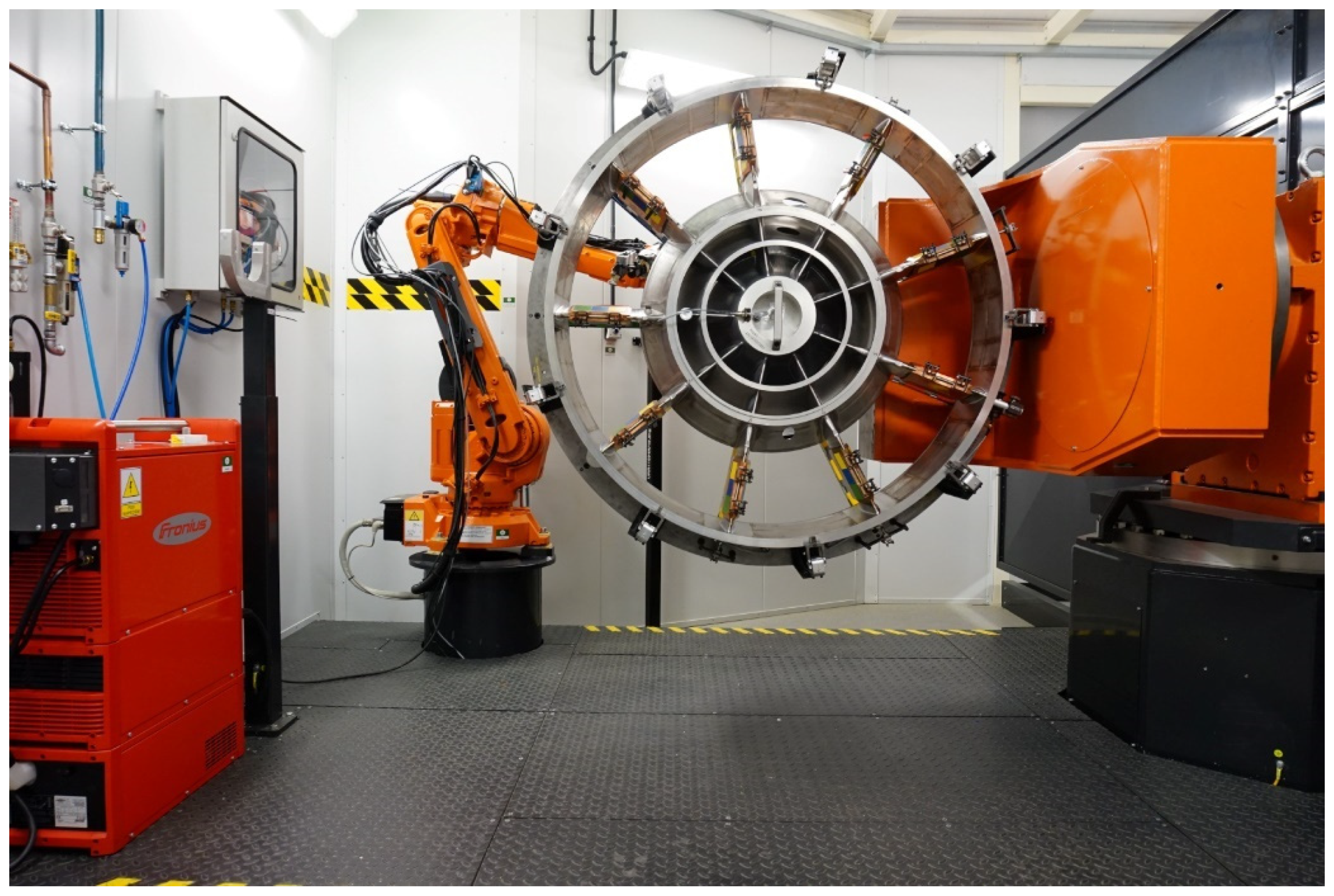
3.1. Research Test Cell
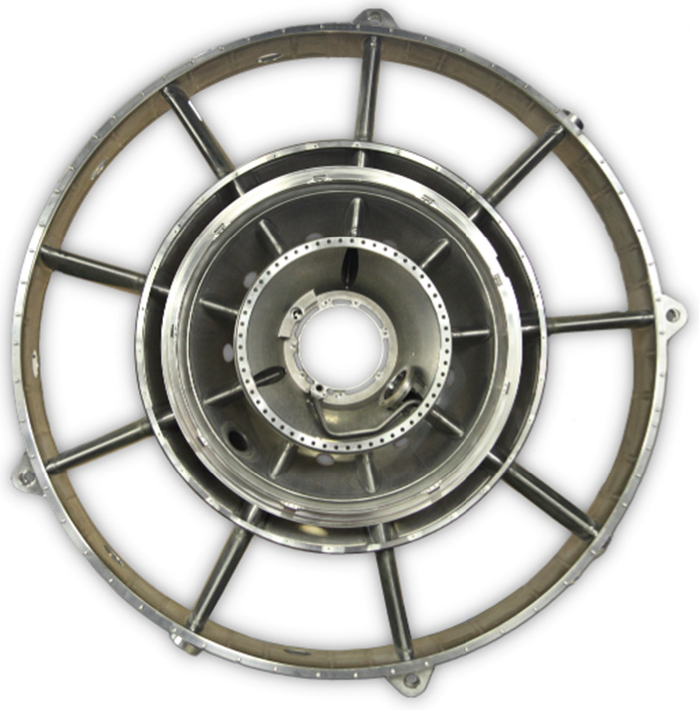
The tests were carried out in a production cell that processed TIG welding (
Figure 2). It was designed as a dedicated cell for the processing of specific longitudinal welds of the intermediate case for the PW800 jet engine illustrated in
Figure 3. The total length of the welds was seven m. The struts connected the inner part to the outer ring so this operation had a direct impact on the strength of the whole assembly and the accuracy of its fabrication.
The accuracy and repeatability of the process in the production cell, depended on many factors. With the large part (the diameter was approximately 1400 mm), which was composed of several dozen smaller components, it was difficult to achieve repeatability of the input parameters. It could be ensured to a limited degree during manual assembling procedure before the welding operation.
The primary components of the production cell shown in
Figure 2 included an ABB IRB 2600ID six-axis industrial robot with an ABB IRBP B1000 five-axis positioner with a capacity of 1000 kg. An automated fixture, mounted on the positioner, featured pneumatic actuators, a number of sensors to verify the fixture status, and the position and orientation of the part in the fixture. The TIG welding process was carried out with a Fronius MagicWave 5000 automatic welder, which controlled the process settings with an internal program.
The production cell also featured a Keyence CV-S200M video system, complete with a custom calibration system for the camera itself and the position of the TCP of tungsten electrode in the welding torch.
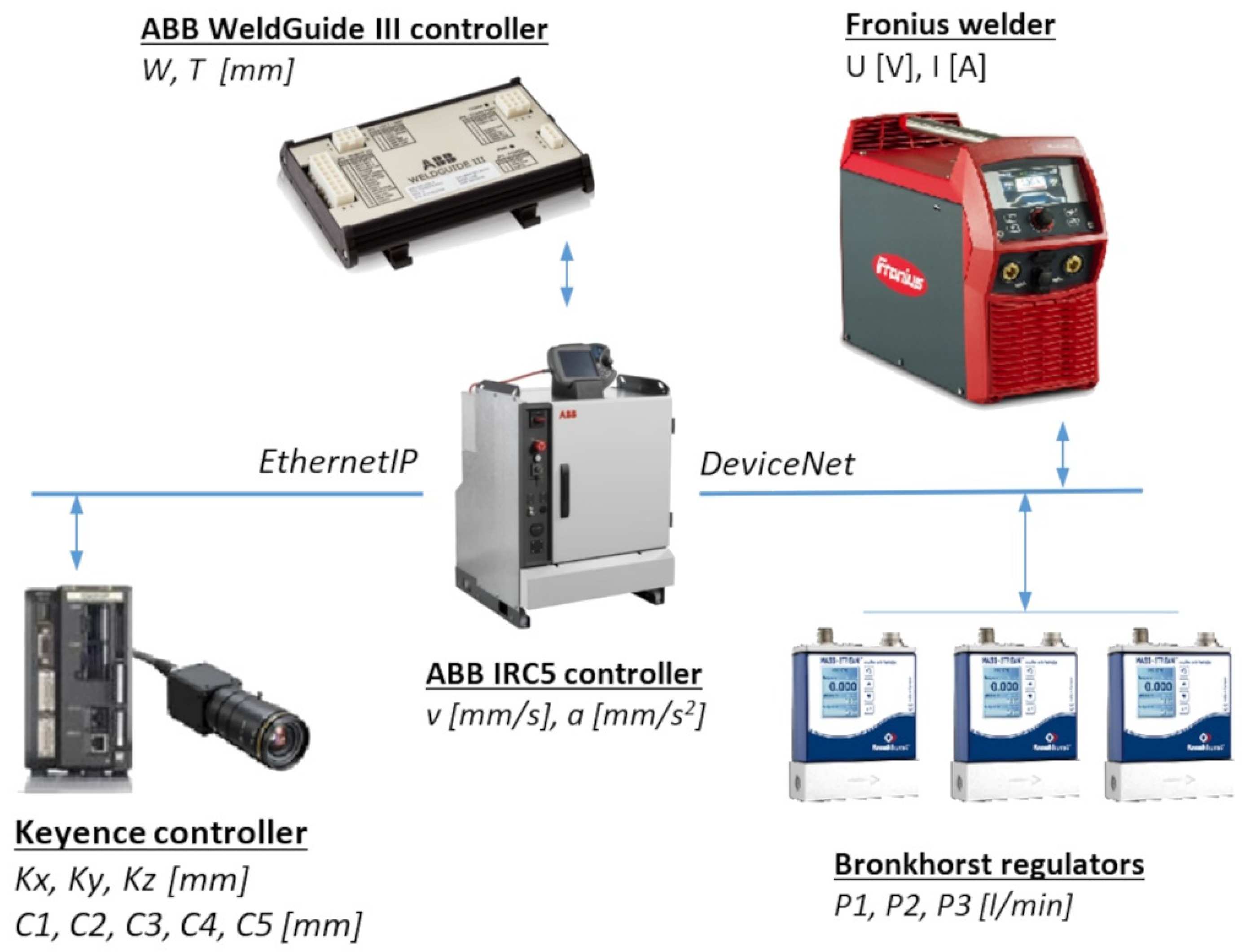
The master control unit of the production cell was an ABB IRC5 industrial robot controller. Aside from operating the motion control program of the robot and the positioner, the unit also handled the communication with other devices installed in the production cell.
The connection diagram of the production cell devices was based on EthernetIP and DeviceNet and is illustrated in
Figure 4.
The workstation also had a safety system managed by an ABB Pluto controller, which allowed the automatic operation at the cell only when all protections were secured. The operator could display the processing data and parameters outside the station, using an HMI panel and the visual compensation control provided by the video system.
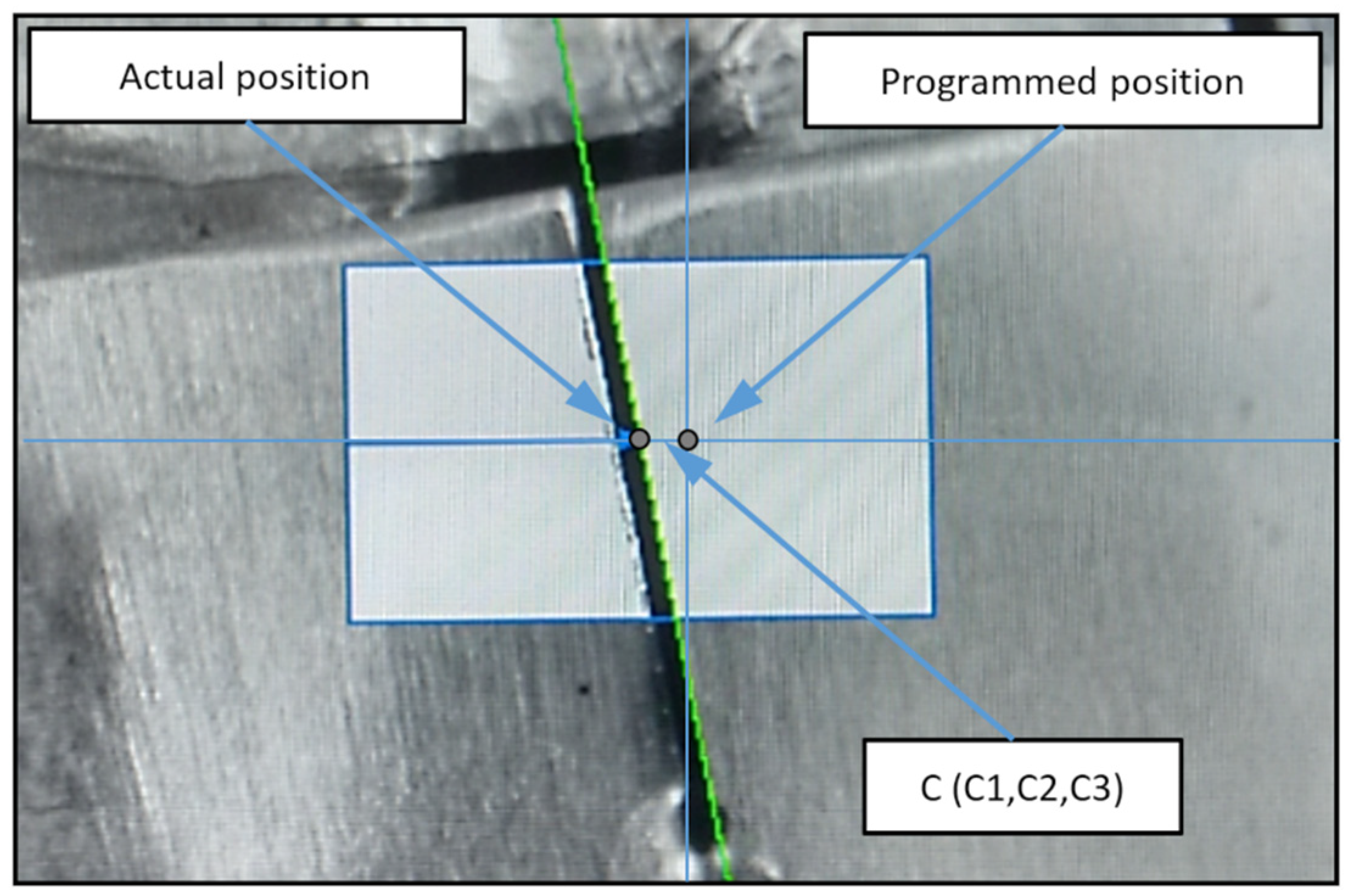
To adjust the robot motion path to the manufacturing tolerances of the part presented for processing, the production cell featured a vision system for trajectory correction. It read the locations of the workpiece edges (
Figure 5) and output the relative values of its locations to the robot controller, which used the data to shift the pre-programmed path.
The trajectory was corrected directly before the process, which ensured the correct location of the welding path relative to the edges being welded, according to the applied manufacturing process assumptions. The calibration of the welding torch combined with a camera was completed before processing the TIG welding and needed to be performed every time the tungsten electrode was replaced.
3.2. Identification of Essential Process Parameters
In the first step of the research, the manufacturing process and devices of the production cell were studied to identify which data affected the process, meaning the input data and the data that were the direct contributors to the process results. Each manufacturing process had many variables and parameters, the identification of which required in-depth understanding of the structure and operating principles of the devices involved.
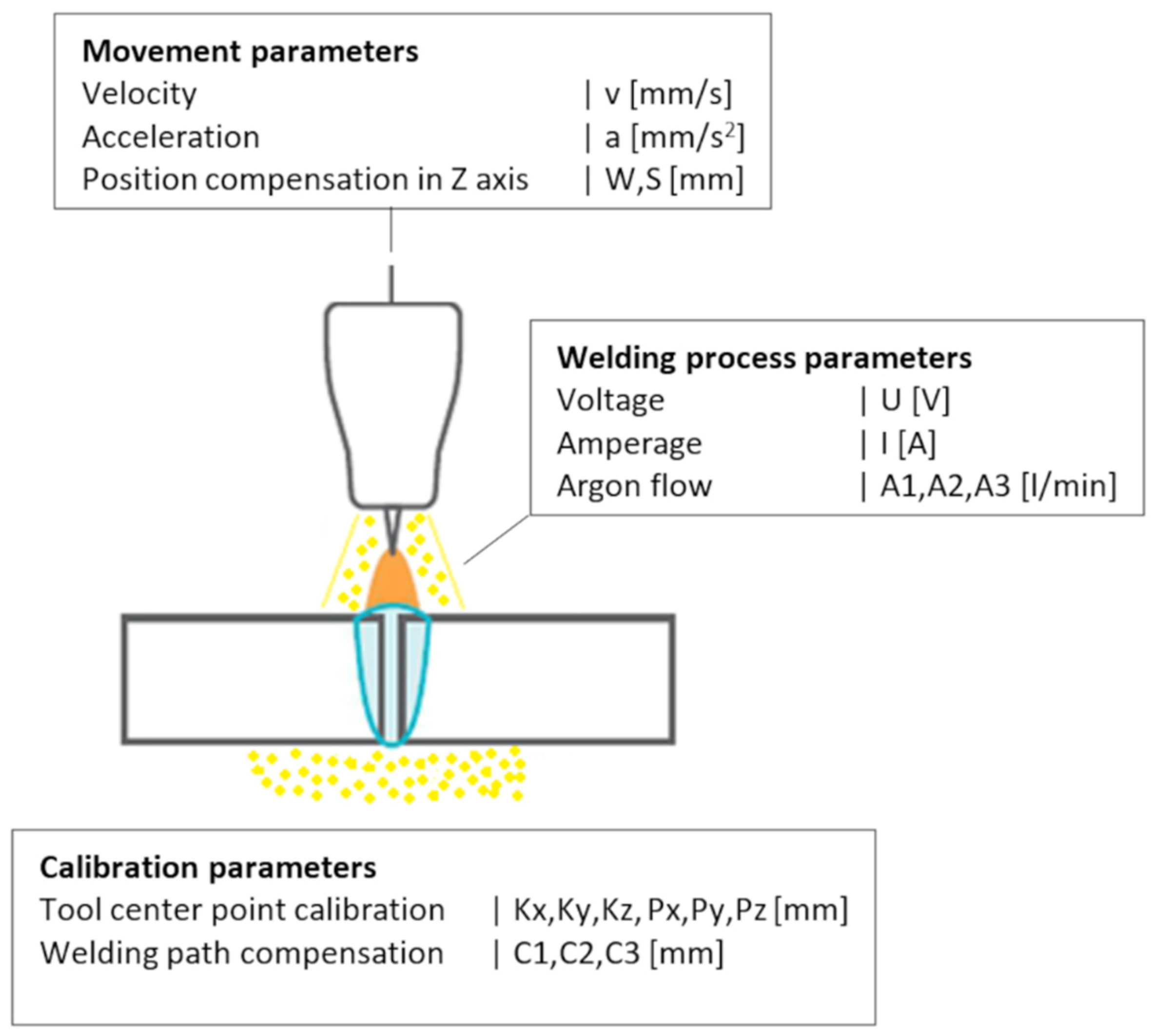
Figure 6 provides a schematic summary of the identified parameters in three subgroups: calibration parameters, motion parameters, and welding process parameters.
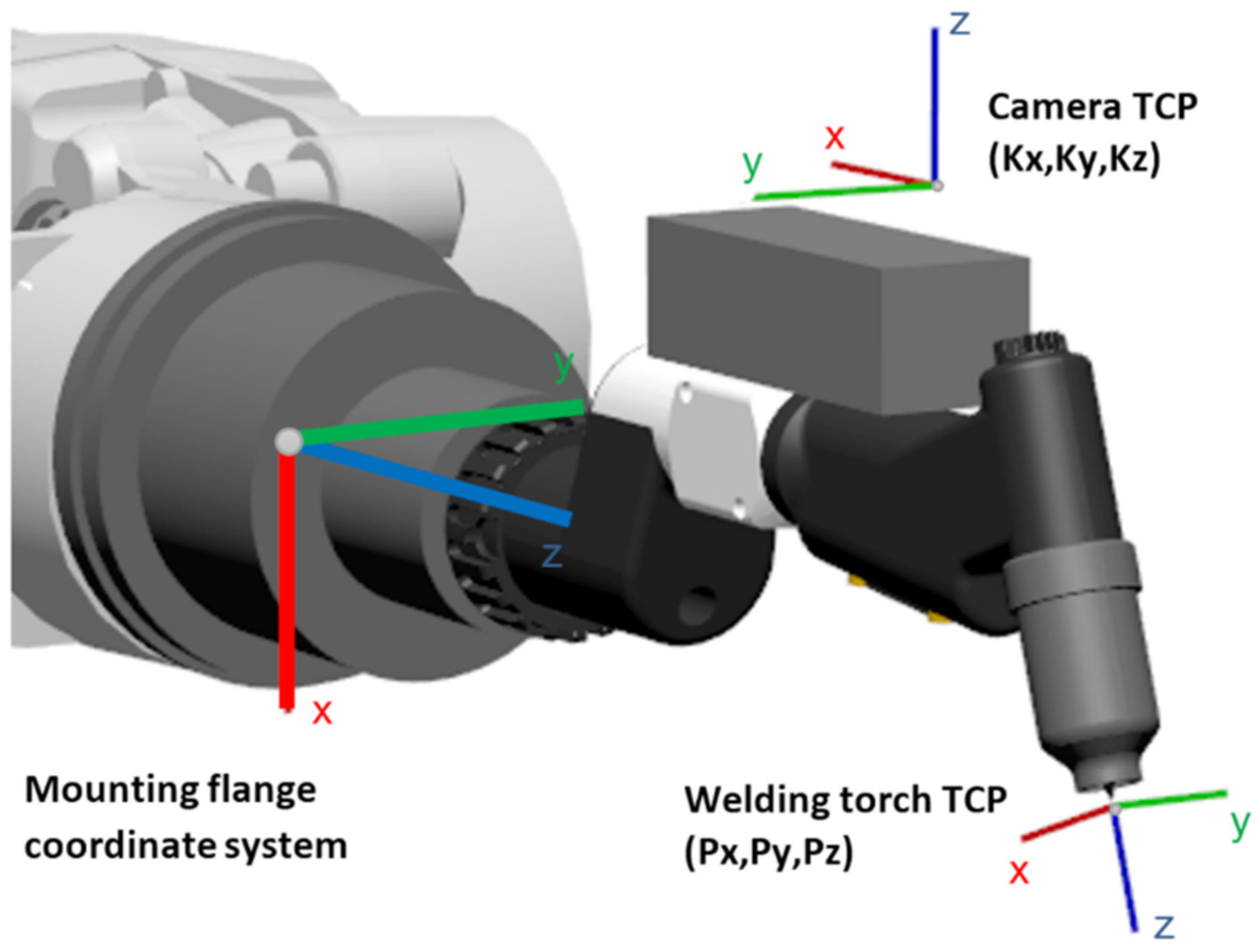
To provide a proper correlation of the measurements from the vision system and the robot positioning system, a dedicated calibration routine was developed. Collected and written data described the actual position of the welding torch electrode (torch TCP: Px, Py, Pz) and the camera point of focus (camera TCP: Kx, Ky, Kz) in the coordinate system referenced to the industrial robot’s tool mount flange (
Figure 7).
The vision system was responsible for finding the welding path and calculating the corrections for robot. The welding trajectory was analyzed directly before welding and the analysis results were stored in the robot controller to be used in the welding process. Each welding path was defined by three points and compensation was specified for each of the trajectory point as C1, C2, C3 (
Figure 5).
Parameters for the TIG welding process were the values which define the process flow. The primary variables were welding current (I) and welding voltage (U) provided by the welder machine, which was a constant current source in this case. The flow parameters of shielding gas distribution to the weld face and to the weld root were also considered (A1, A2, A3, see
Table 2 line 5). They were executed by the gas flow controllers, with the specific values being stored in the robot’s program and set and verified in every step of the process.
It was critical for the robot to maintain a uniform welding speed (v) with a low motion acceleration (a) to limit vibration, which was detrimental to the welding process.
Given the large dimensions of the part and the tolerances acceptable in the manufacturing process discussed here, the WeldGuide system was used to maintain a fixed welding arc length by correcting the electrode distance from the workpiece surface. Main parameters of the WeldGuide system were correction value per measurement step (W, see
Table 2 line 8) and the total incremental correction value (S, see
Table 2 line 8).
For each of these parameters, their signal sources were defined, as well as the properties, which included the value type, the value range and units, and the measurement frequency. The defined parameters are listed in
Table 2.
Direct communication between the IRC5 controller and the devices at the production cell allowed the read and save defined in-process parameters as the designed structure, in order for them to be used in further data analysis.
After improvements were made for the programs already operating on the controller, a data recording frequency of over 40 times per second was achieved. Considering that a single weld seam was made in approximately 1 min, approximately five MB of data were produced from a single part in the robotic TIG welding operation.
3.3. Classification of the Output States
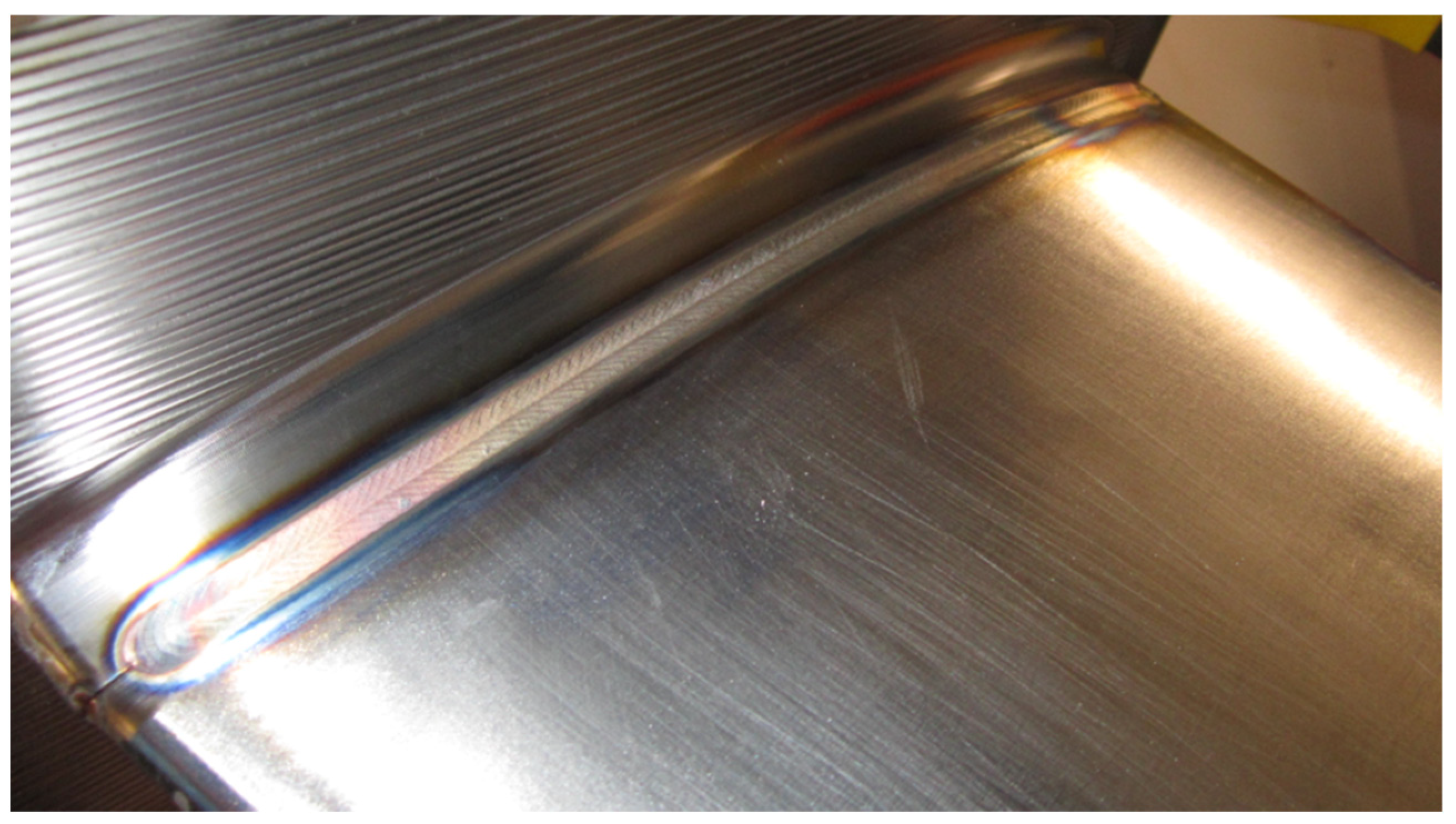
The result of the welding process was the weld seam, a permanent joint of two workpieces of a material. The output state could be considered to be conforming (
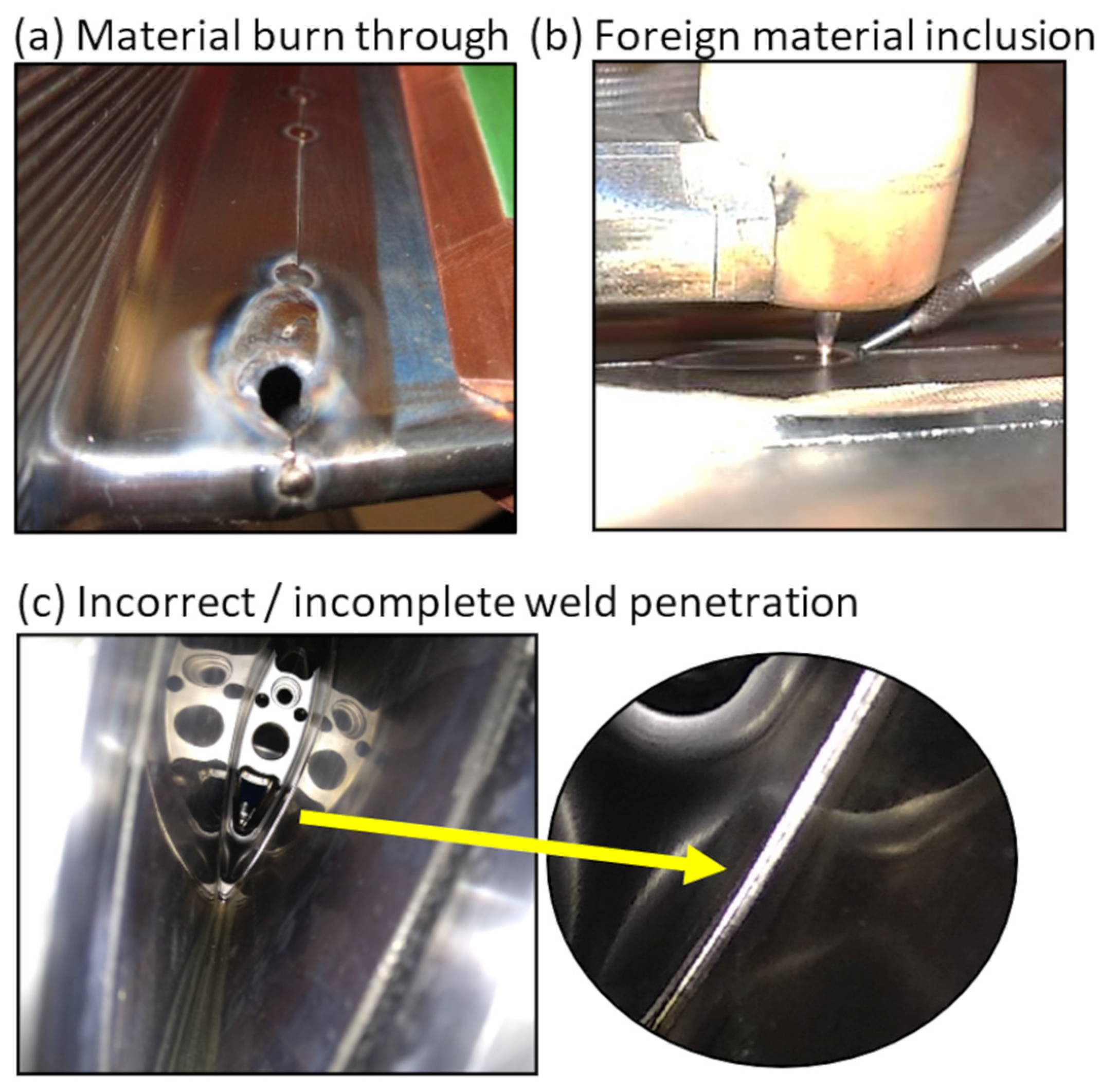
Figure 8) if it met the requirements of the reference standards and was accepted by quality control. The most frequent non-conformities could be classified into three categories, which included material burn through, foreign material inclusions, and incomplete weld penetration (
Figure 9). The set of output states is listed in
Table 3.
Material burn through largely occurred when the limit value of the gap between the edges of joined materials was exceeded (
Figure 9a). This could be caused by material stress release due to temperature increase during welding.
Foreign material inclusion in the weld seam could come from the welding electrode itself if, due to disturbances in the arc welding process, it was melted into the welding pool of the base metal (
Figure 9b).
Incomplete weld penetration was one of the main root causes for reworking the weld types discussed here. The defect could appear at different weld lengths (
Figure 9c)
Weld defects were detected after the process by quality control and, in some cases, by the operator, if the defect was noticeable. Non-conformities characterized by missing weld penetration were only detected during visual inspection using borescopes, FPI, or X-ray inspection.
3.4. Data Analysis and Determination of the Significant Parameter
The welding parameter values listed in
Table 2 were stored to files with a designed structure to facilitate downstream analysis. For each production part, the data for all 36 manufactured welds were collected.
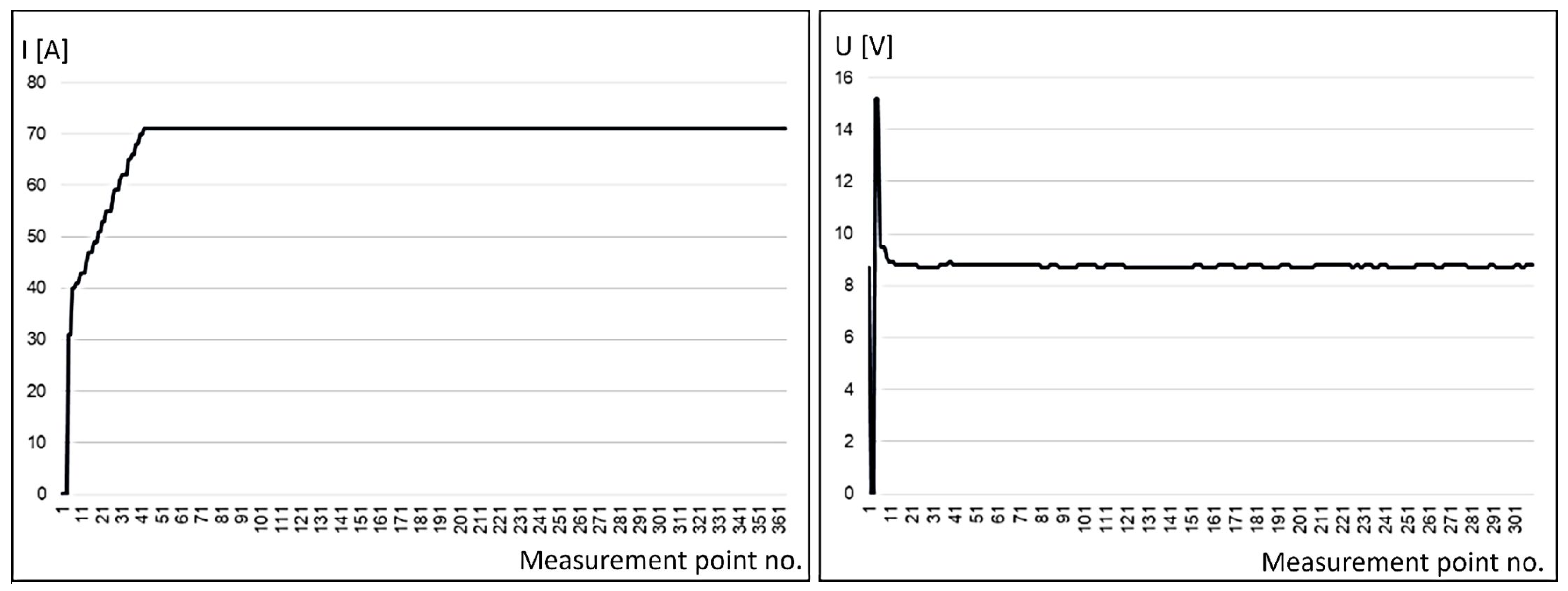
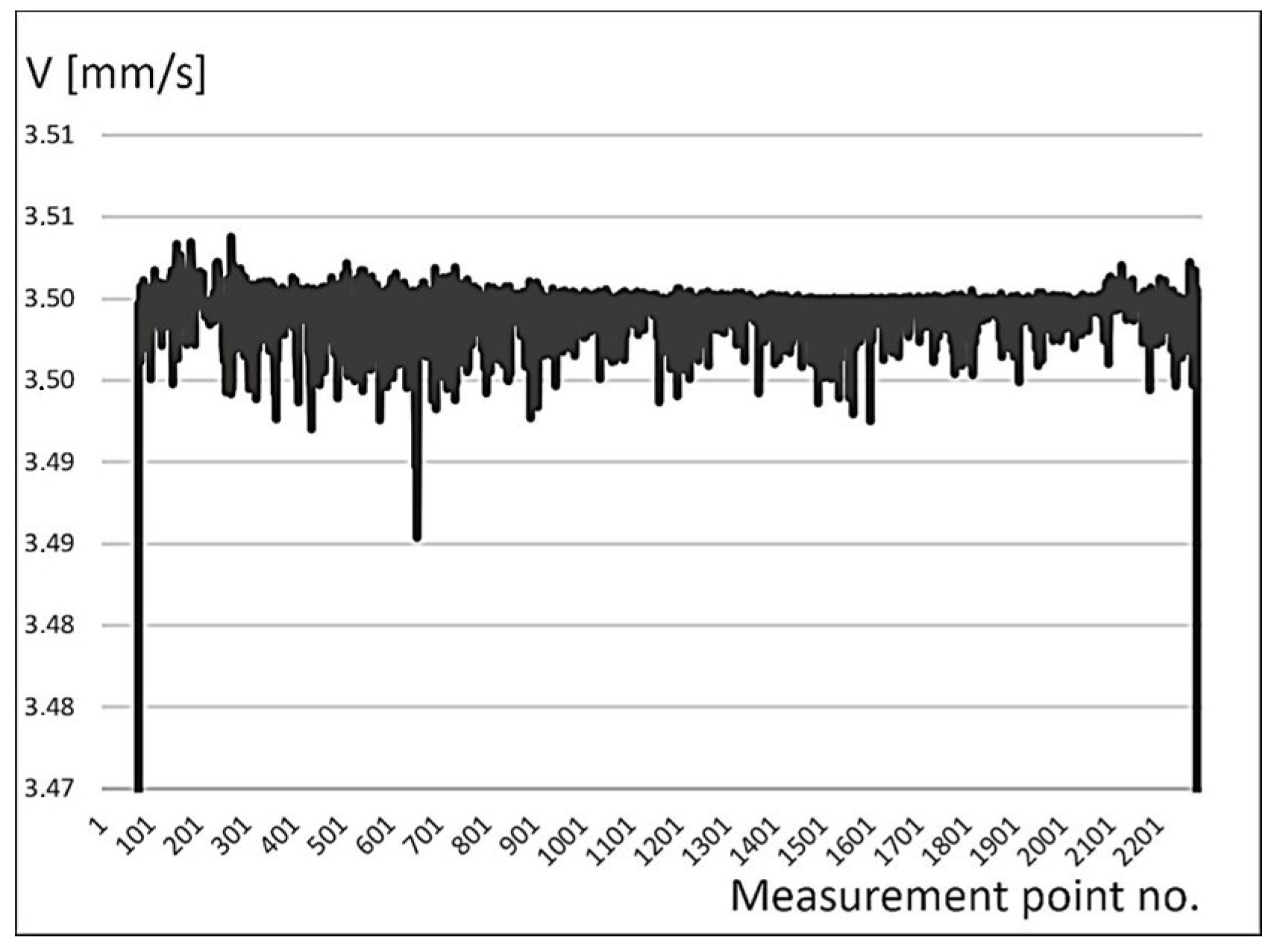
Figure 10 and
Figure 11 show example trends for a few of the selected and recorded parameters, which included welding current and voltage (
Figure 10) and the welding speed (
Figure 11).
The data produced from the saved parameter trends were collated with the quality control data, which included the welding results for all welded joints.
Table 4 is a matrix of defects for each weld of the considered sample of part numbers.
The analysis of the collected quality control data from the welding process operation considered in this work revealed that the most prevalent weld defect in the operation was missing weld penetration along a certain part of, or along the entire weld.
One of the assumptions of the project was to implement the solution in production conditions using the existing equipment. The main determining factor was the limited computing capacity of the robot IRC5 controller. To make a comparison of the collected signals of the defined welding process parameters that are listed in
Table 2, indicators were calculated using statistical functions, which included the following:
standard deviation;
variance;
skewness;
kurtosis;
average value.
Analyzing the data, there were more then 900,000 records of data per one production part, which resulted in about 1500 indicator values for one part. The batch of 50 production parts generated 1800 values for only one indicator type. All the indicators calculated for the groups of the main welding parameters and the WeldGuide system parameters were analyzed. Examples of indicator values for welding voltage and speed are shown in
Table 5.
The calculated indicators were compared with the quality control data listed in
Table 4. The analysis of the results provided a determination of the limit value of an indicator for which the welding result was conforming. The values of the skewness indicators, whose absolute values were higher than the limit value, indicated the presence of weld defects.
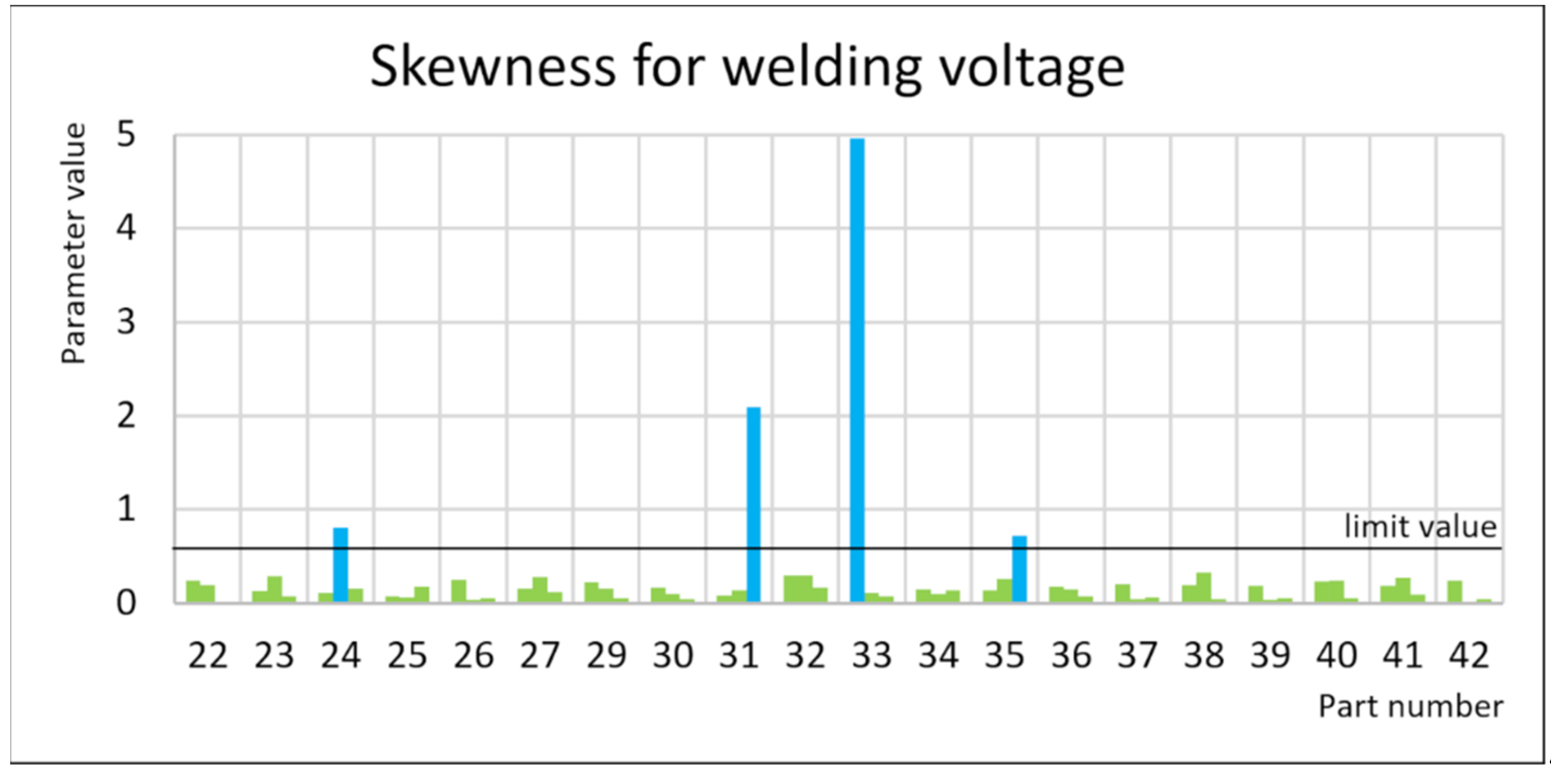
Figure 12 shows a set of the absolute values of welding voltage trend skewness (WeldVolt) for three exemplary welds for twenty subsequent parts processed. The determined limit value for this indicator was 0.5 for a conforming welding result. Any indication above this value was directly correlated to incomplete weld penetration (Nb
20) and foreign material inclusion (Nw). A value of the determined skewness above the determined limit value was also a characteristic of the rarer defects, such as missing weld penetration (Nb
70) and material burn through (Np).
The defects for which the parameter limit value was exceeded were approximately 50% of the total number of non-conformities in the welds of analyzed groups of production parts.
3.5. Solution Implementation in the Production Cell
The verification of the developed relation on a set of data from more than 60 production parts allowed the implementation of the solution in the production cell.
The ABB IRC5 controller allowed the implementation of a calculation algorithm directly in the robot’s program. The HMI panel was also used to display the calculation results for their verification.
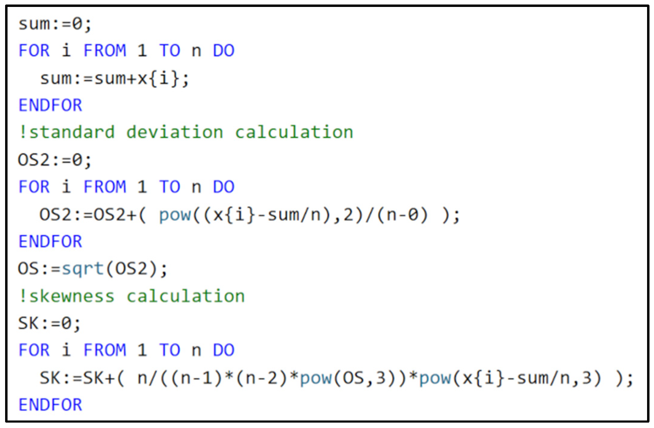
The skewness was calculated with Formula (1), with the standard deviation calculated with Formula (2) [
29].
with:
n—number of measurements;
xi—sequential measurement result;
SR—average value;
SK—skewness;
OS—standard deviation.
The calculations of the skewness indicator were carried out after each seam welding.
Figure 13 shows the calculation algorithm for skewness, programmed in RAPID language from Formulas (1) and (2).
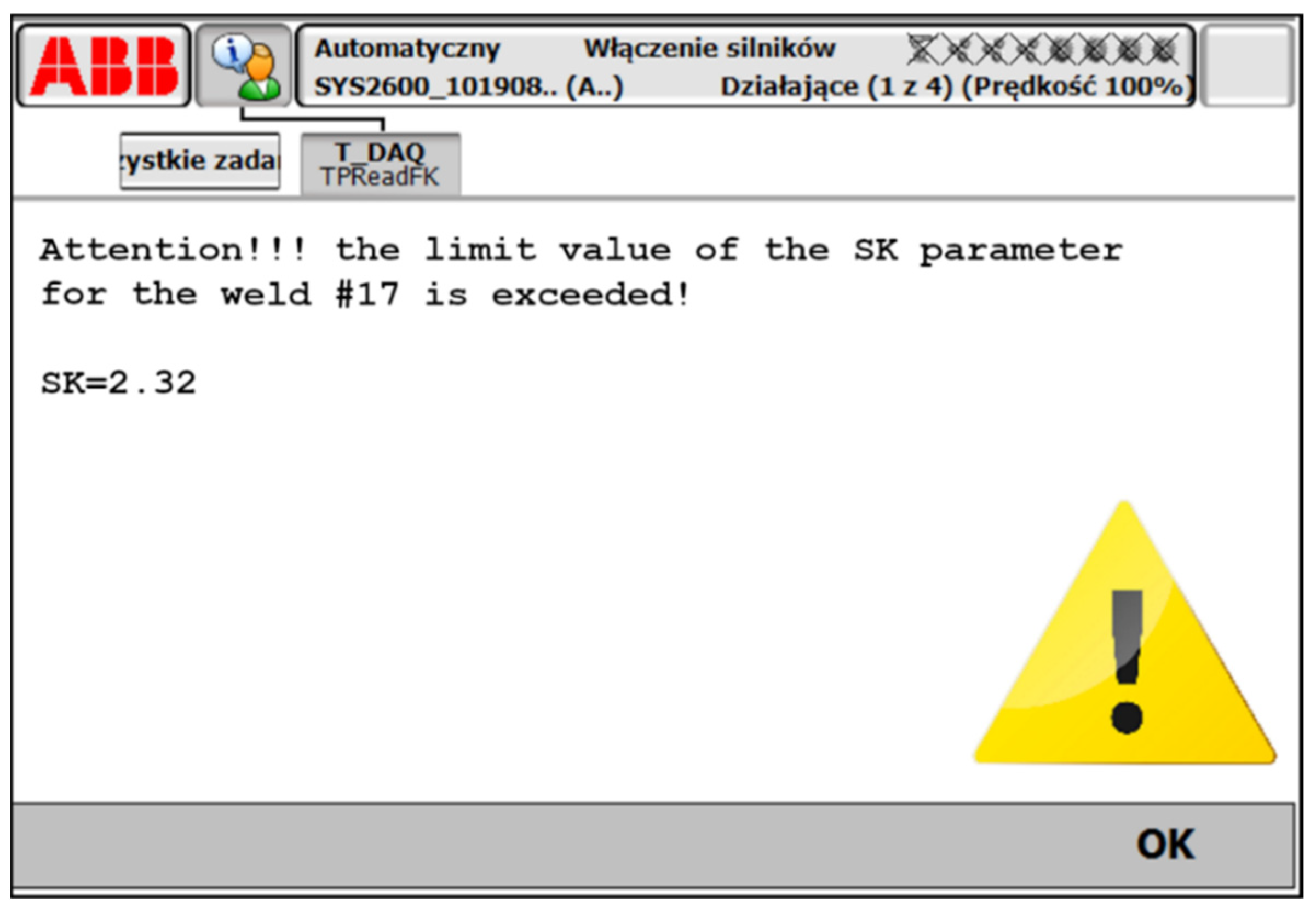
The calculation result was displayed as information available to the operator (
Figure 14), who, in the first implementation stage, decided to act based on the processing instruction. The results were also stored for further analysis to be compared with the weld quality control output data.
To test the introduced solution, a batch of 50 parts was under surveillance. Process and quality control data were collected and analyzed. The results are discussed in the next chapter.


 ,
, 


