
Simulation Oriented Layer of Embedded Software Architecture for Rapid Development of Custom Embedded Systems Virtual Simulators Used in Didactics


Abstract
:1. Introduction
2. Materials
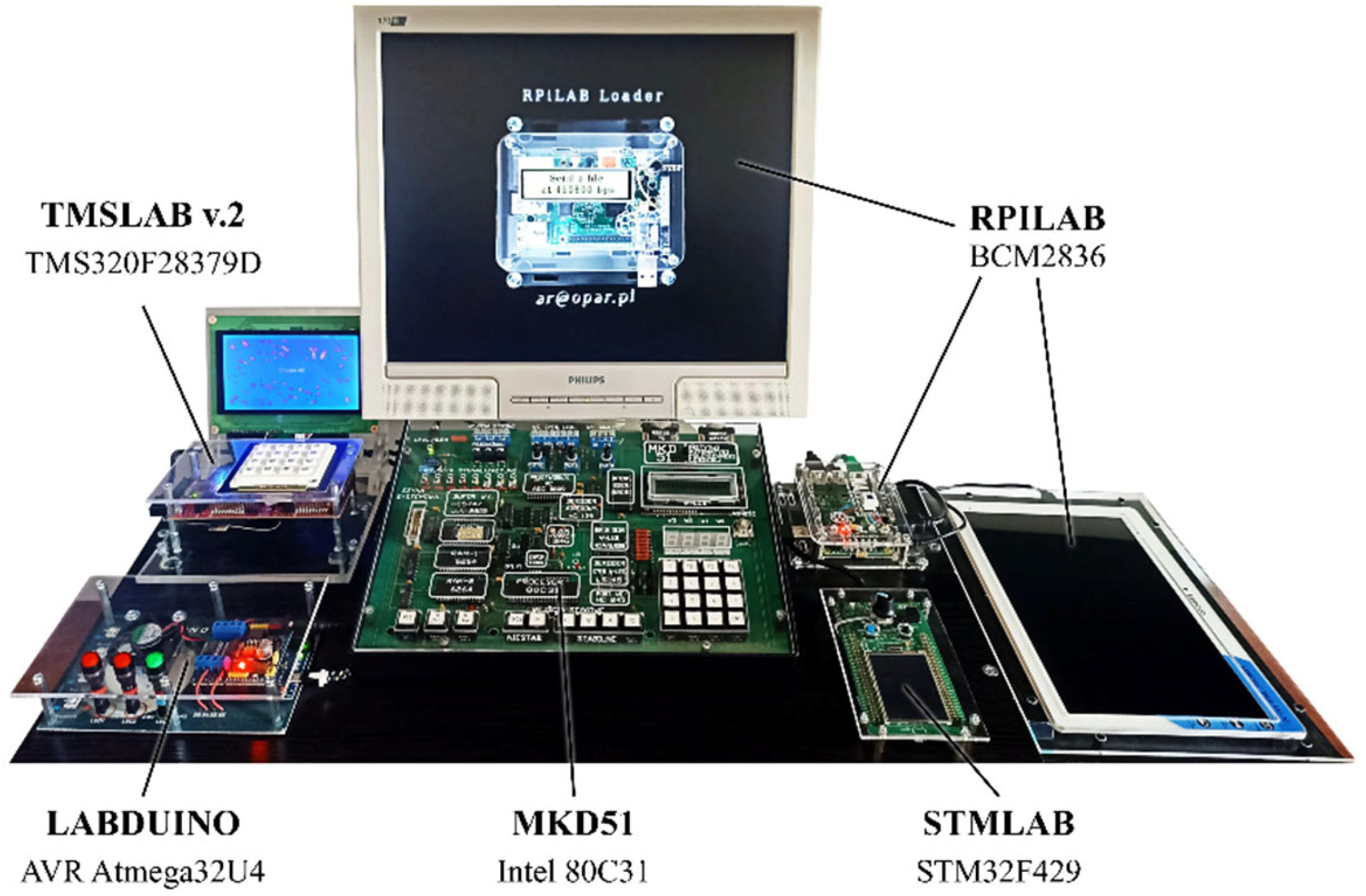
2.1. Didactic Modules for Embedded-System-Programming Teaching
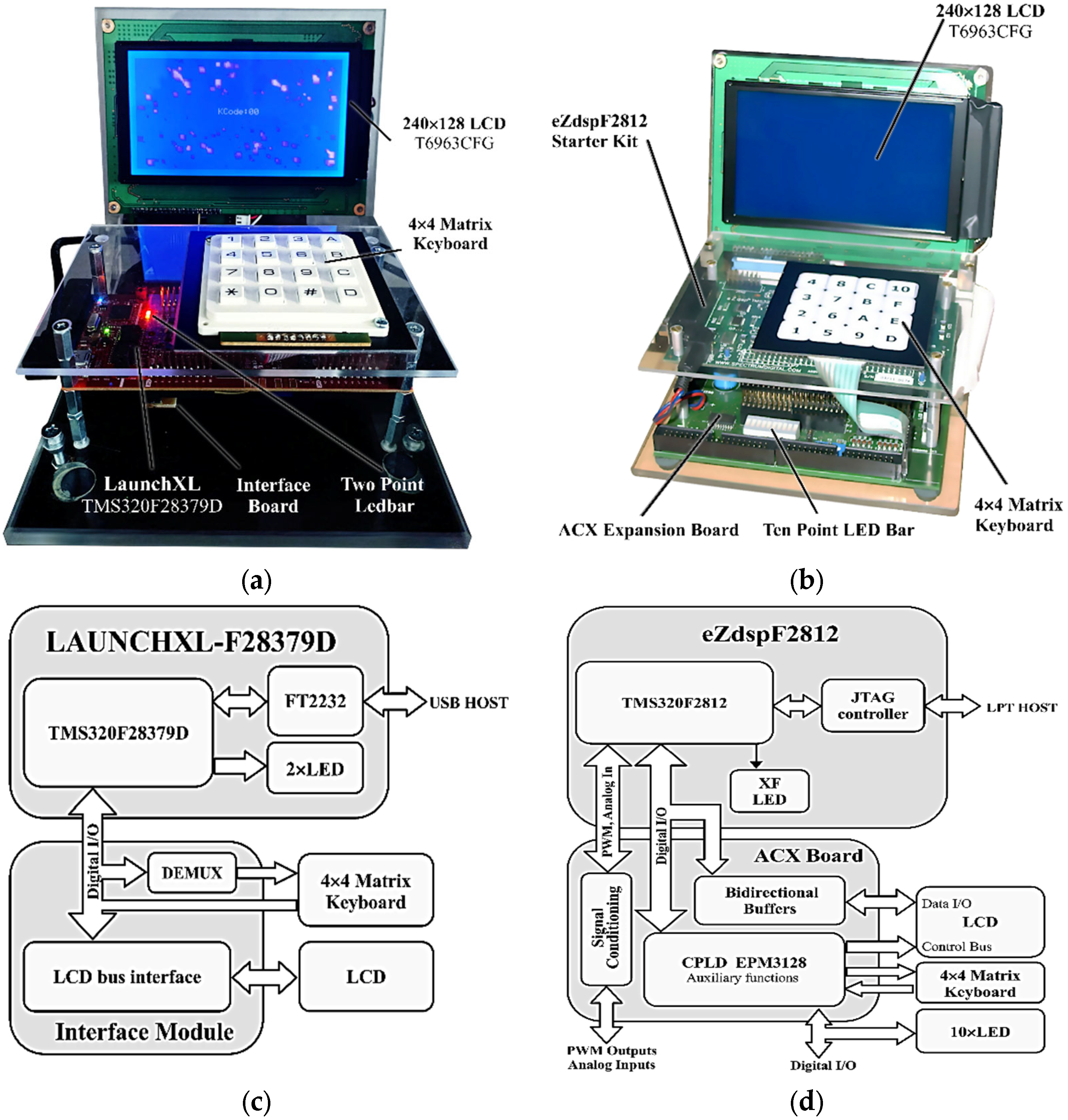
2.2. TMSLAB Module
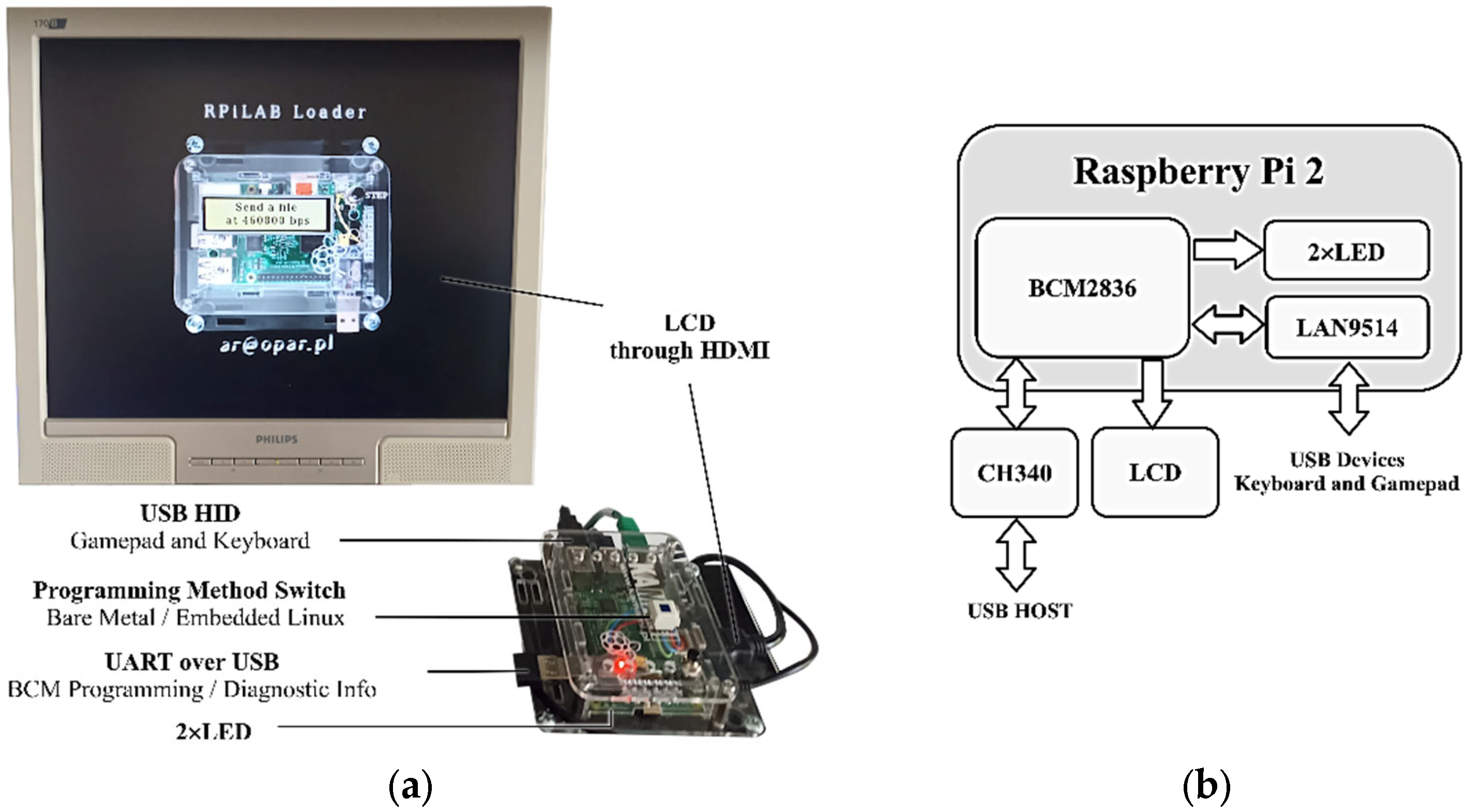
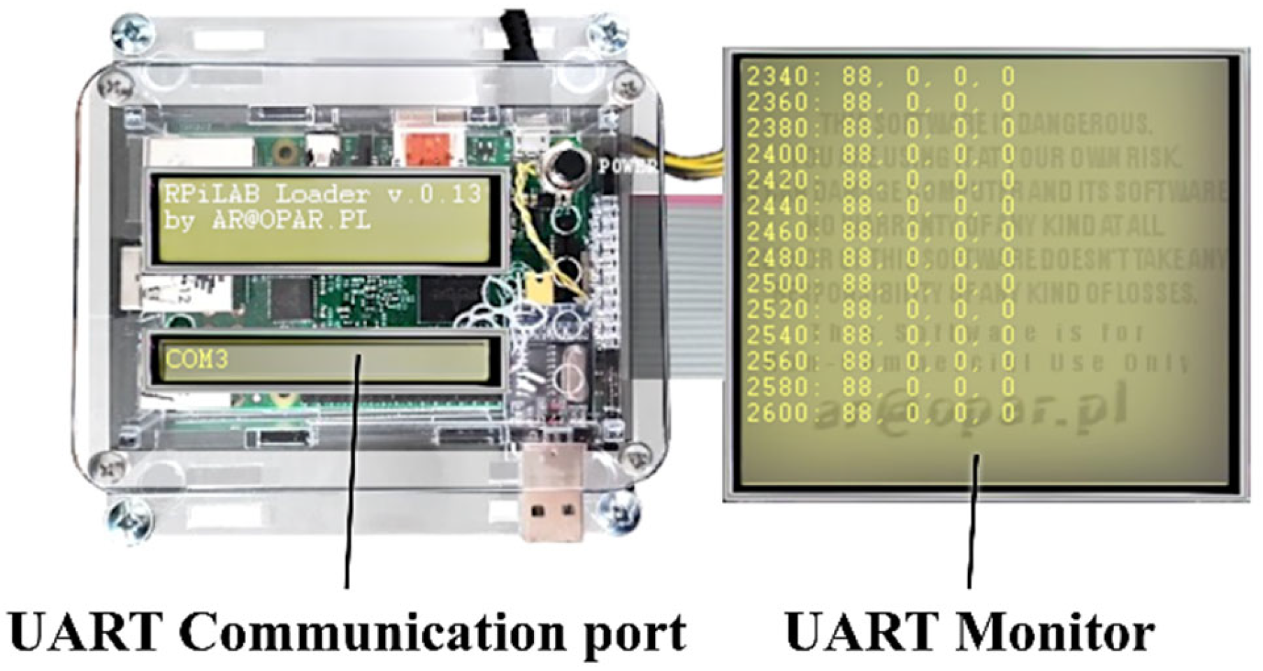
2.3. RPILAB Module
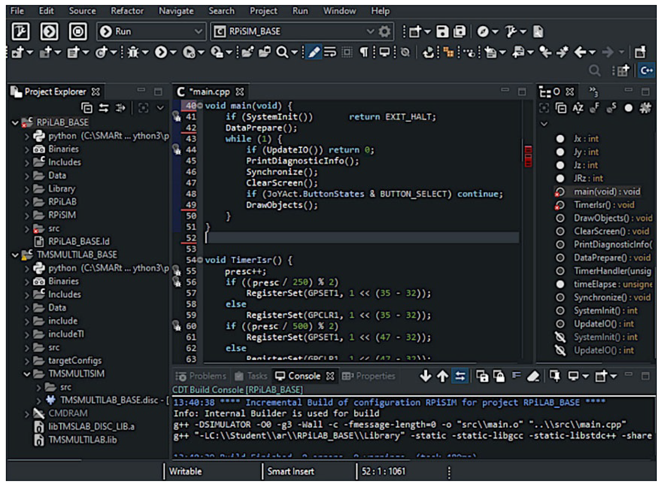
2.4. IDEs Used for Laboratory-Modules Programming
3. Methods
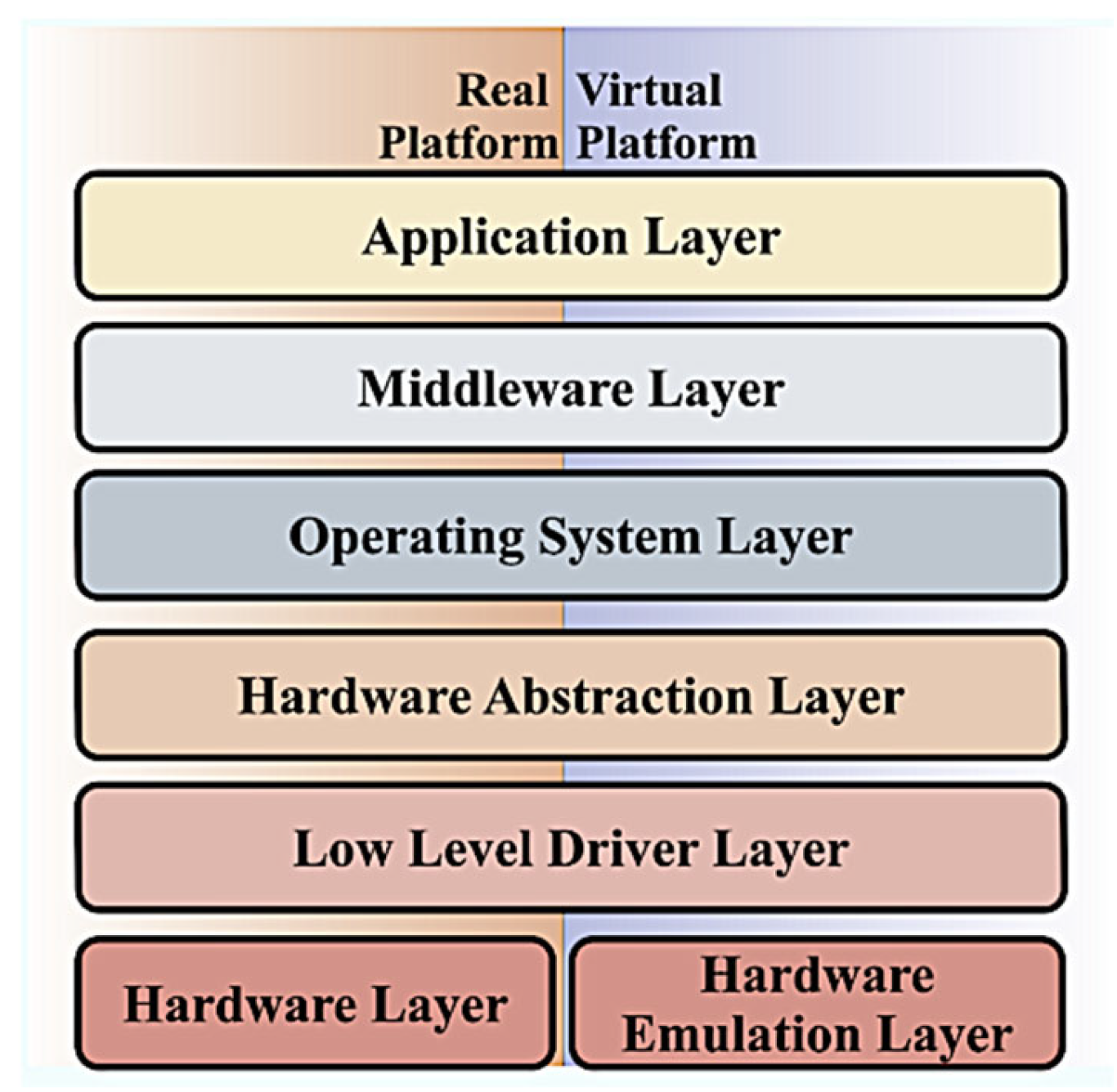
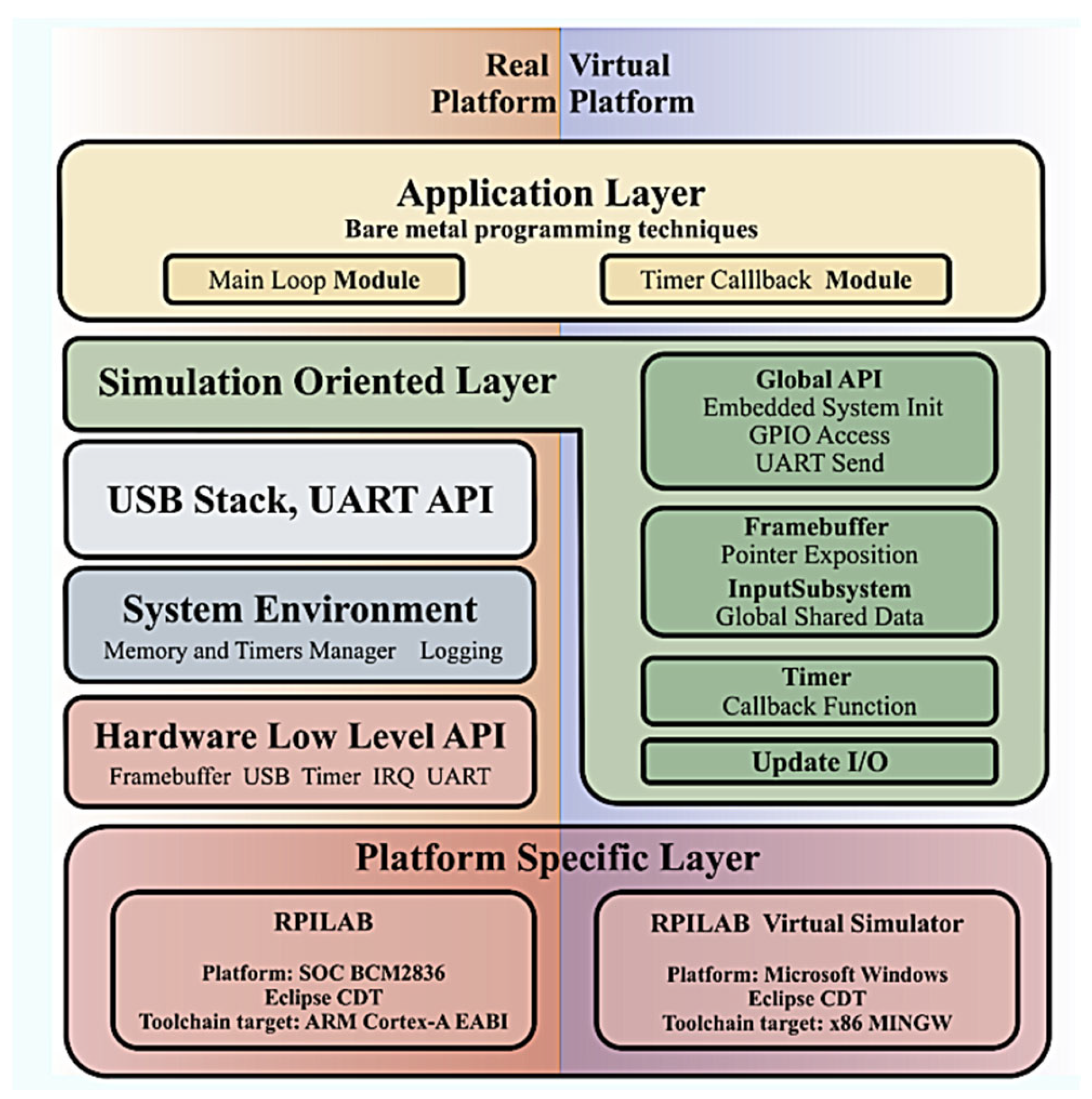
3.1. Common Software Architecture for Embedded Systems Programming
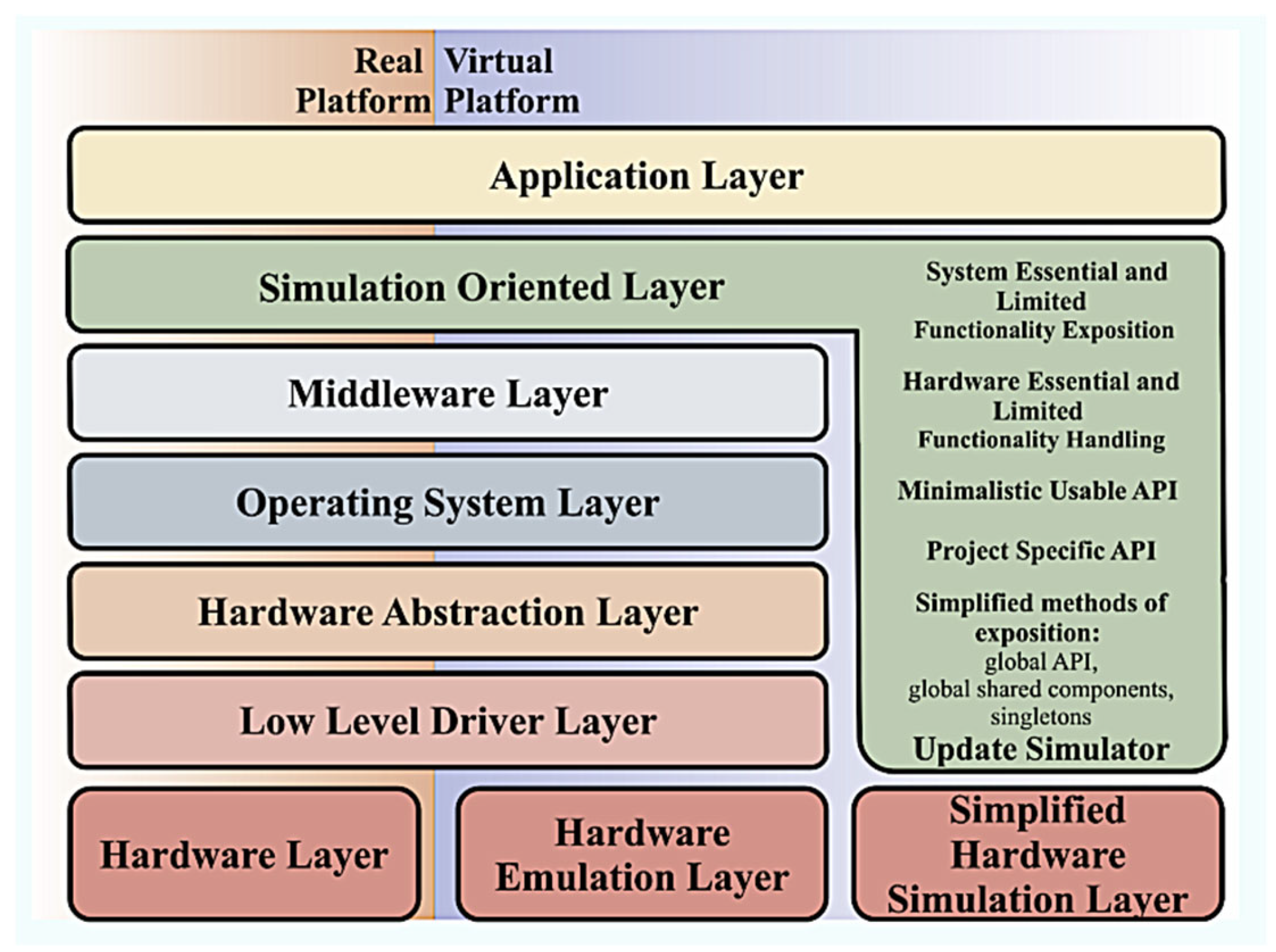
3.2. Software-Architecture Layer for Limited-System-Functionality Simulation
3.3. Simulation-Oriented Layer API Concepts
- -
- global shared data, accessible across a virtual simulator, embedded-software API, and embedded application;
- -
- global functions of system functionality—a simple API to get access to simulated hardware functionality (e.g., SetLed, GetKeyCode, etc.);
- -
- global handlers—functions of specialized purpose (e.g., Interrupt Subroutine Handler) that will be called by lower embedded-system layers and the virtual simulator;
- -
- singletons for hardware handling—composition of both the above concepts, in terms of the C++ language, to gather resources in a single instance of a hardware-handling class;
- -
- global simulator update function—a function that is an entry point to the virtual simulator where all its data will be processed; such a function could be also called a hidden one, inside of a global SOL API.
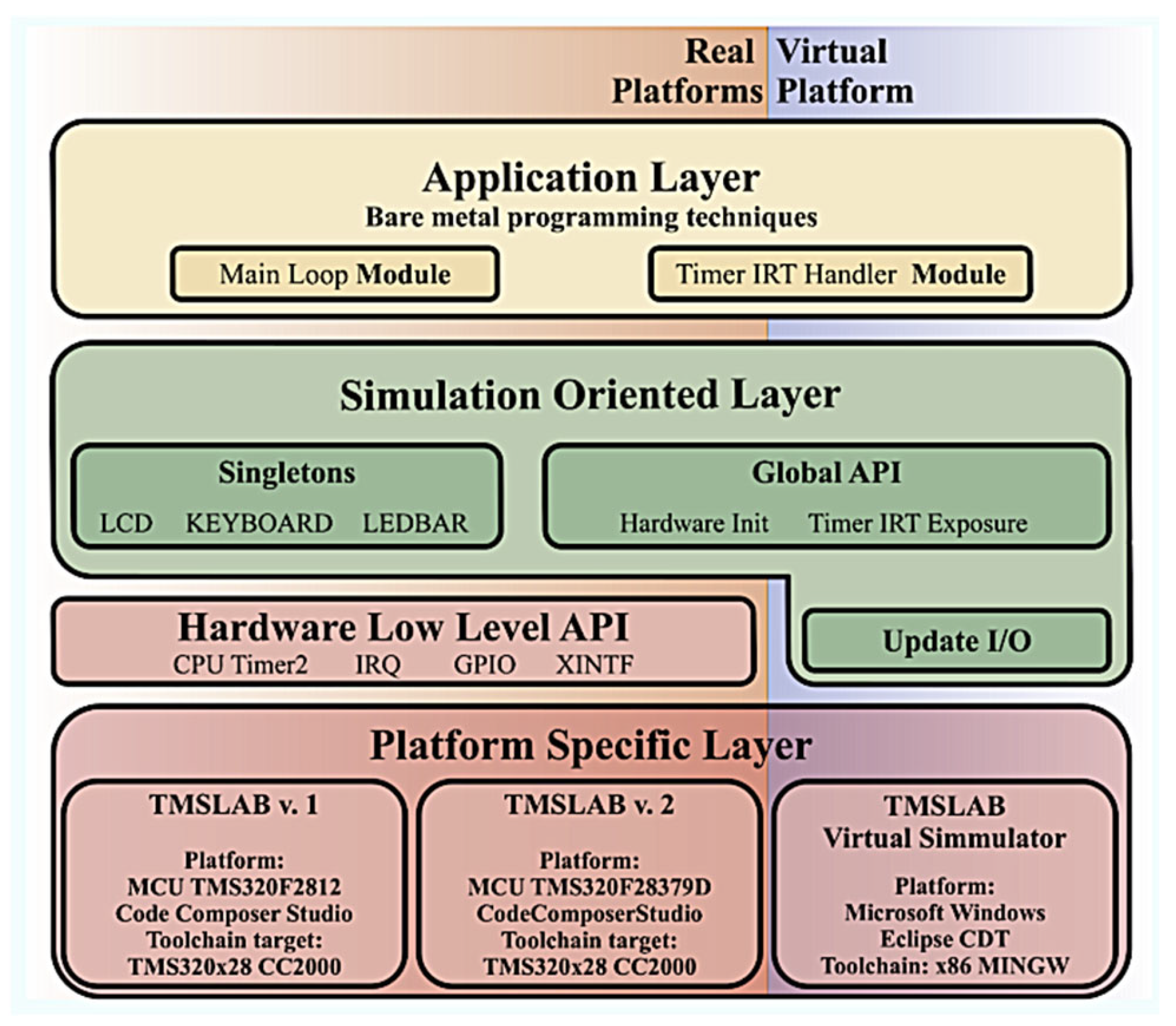
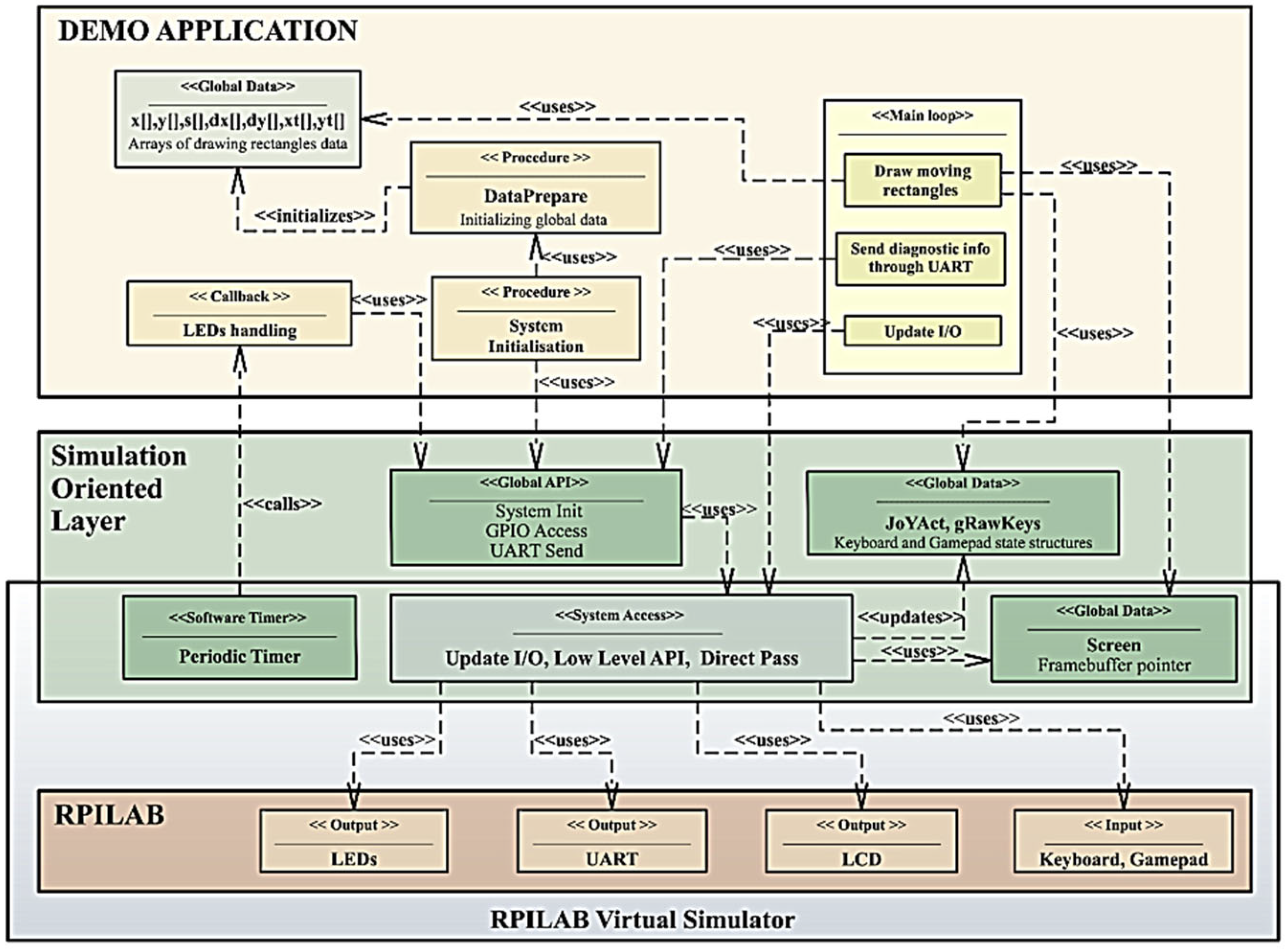
3.4. Simulation-Oriented Layer for TMSLAB and RPILAB Programmed Using Bare-Metal Techniques
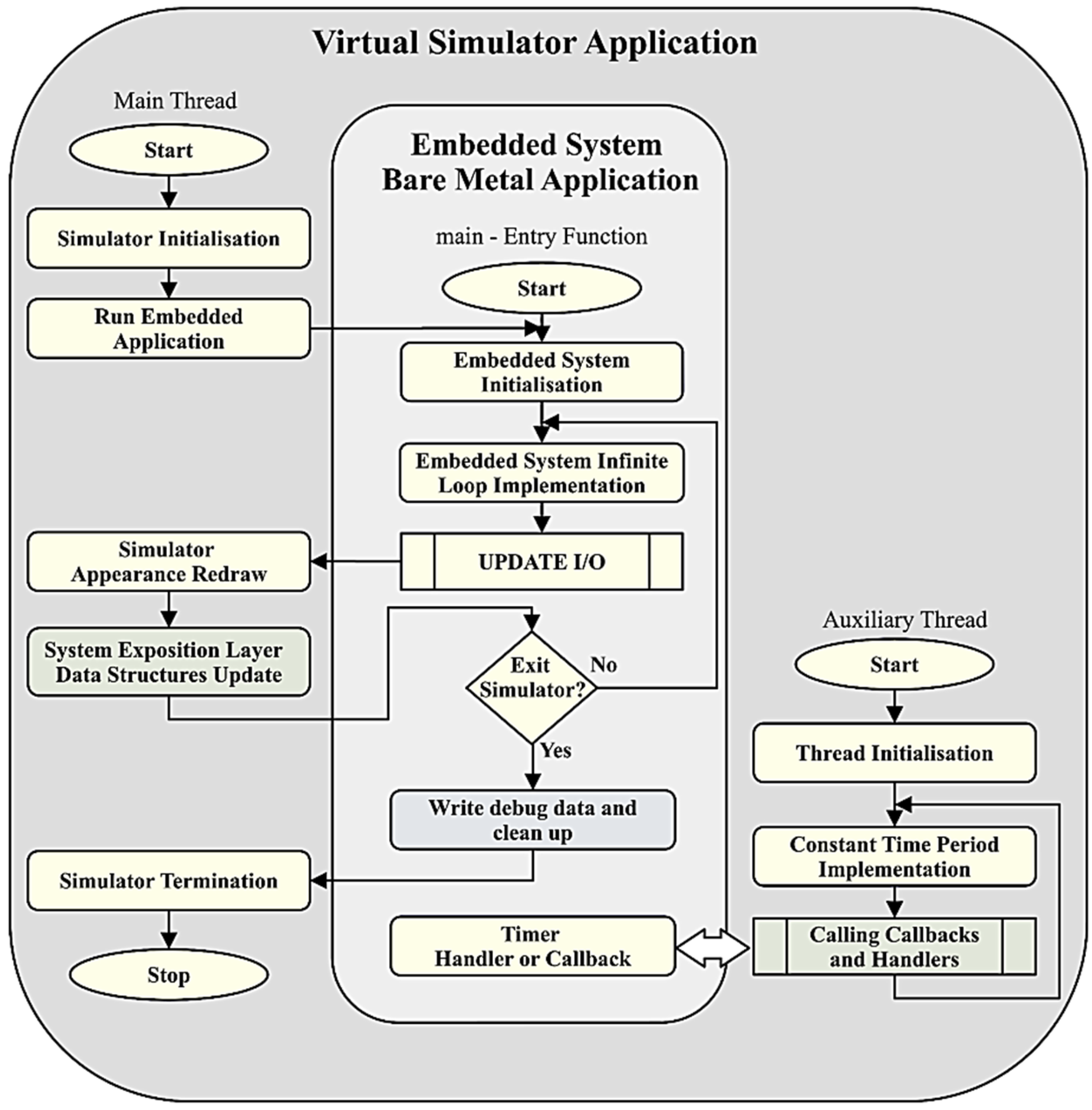
3.5. Virtual Simulator as a Rapidly Developed Stand-Alone Application
4. Results
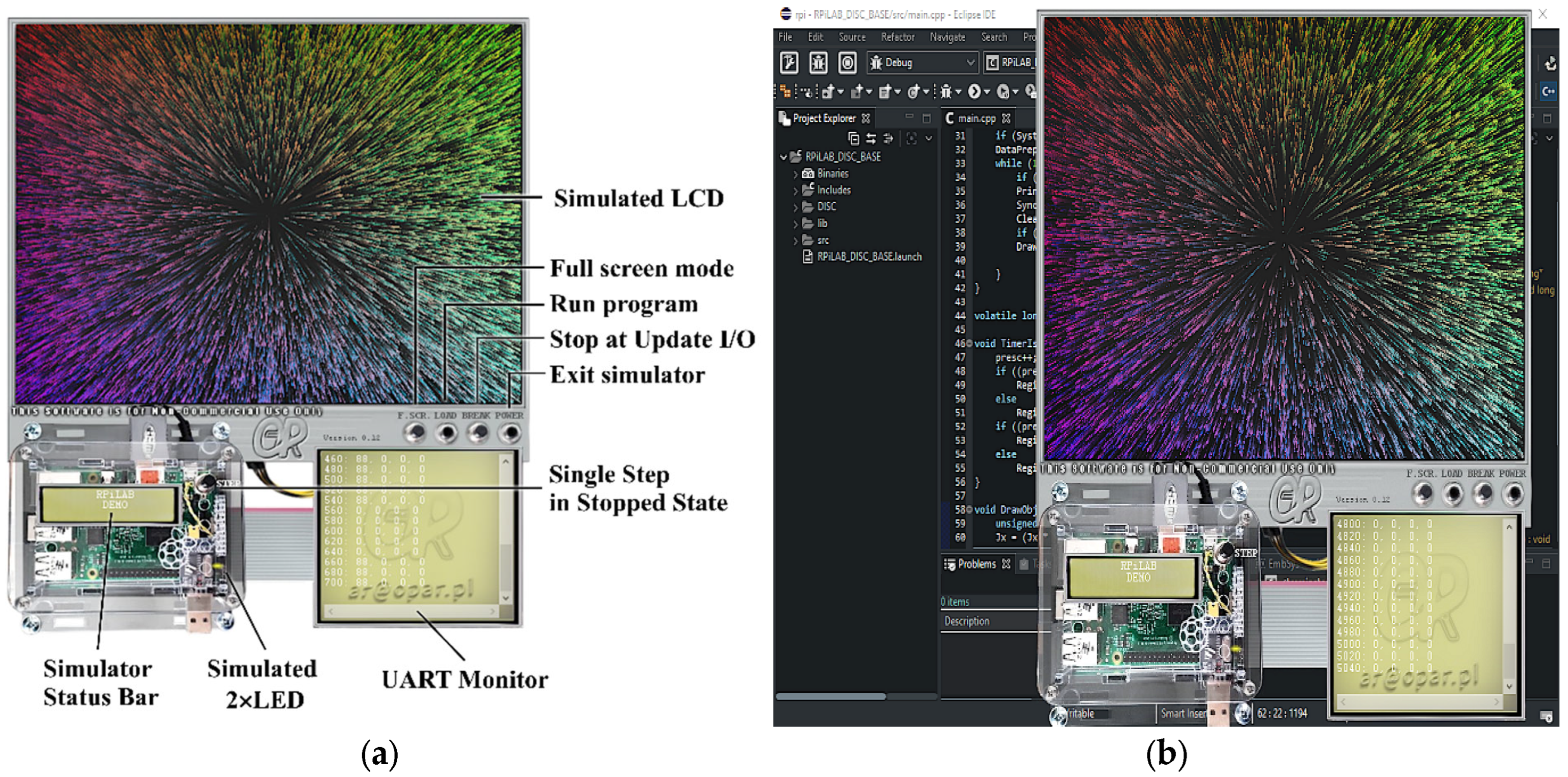
4.1. Virtual-Simulator Implementation on Microsoft Windows
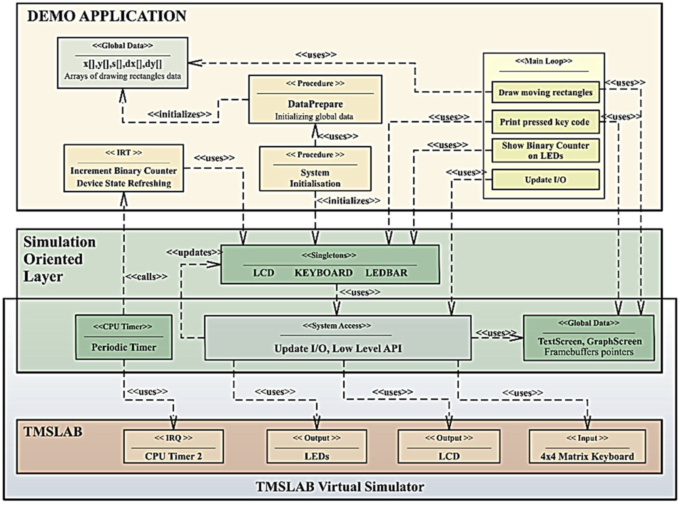
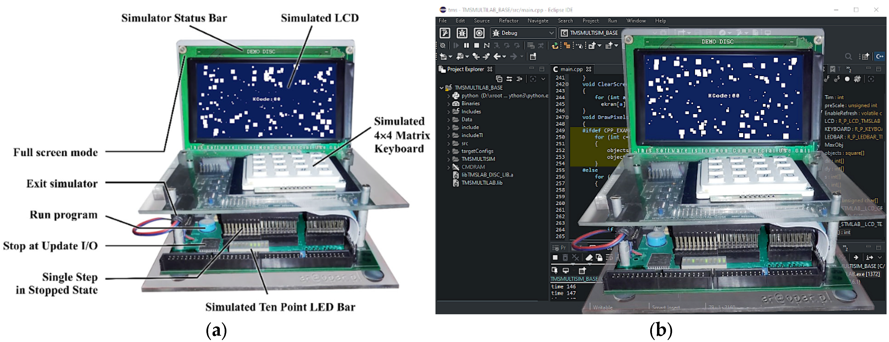
4.2. TMSLAB Virtual Simulator
4.3. RPILAB Virtual Simulator
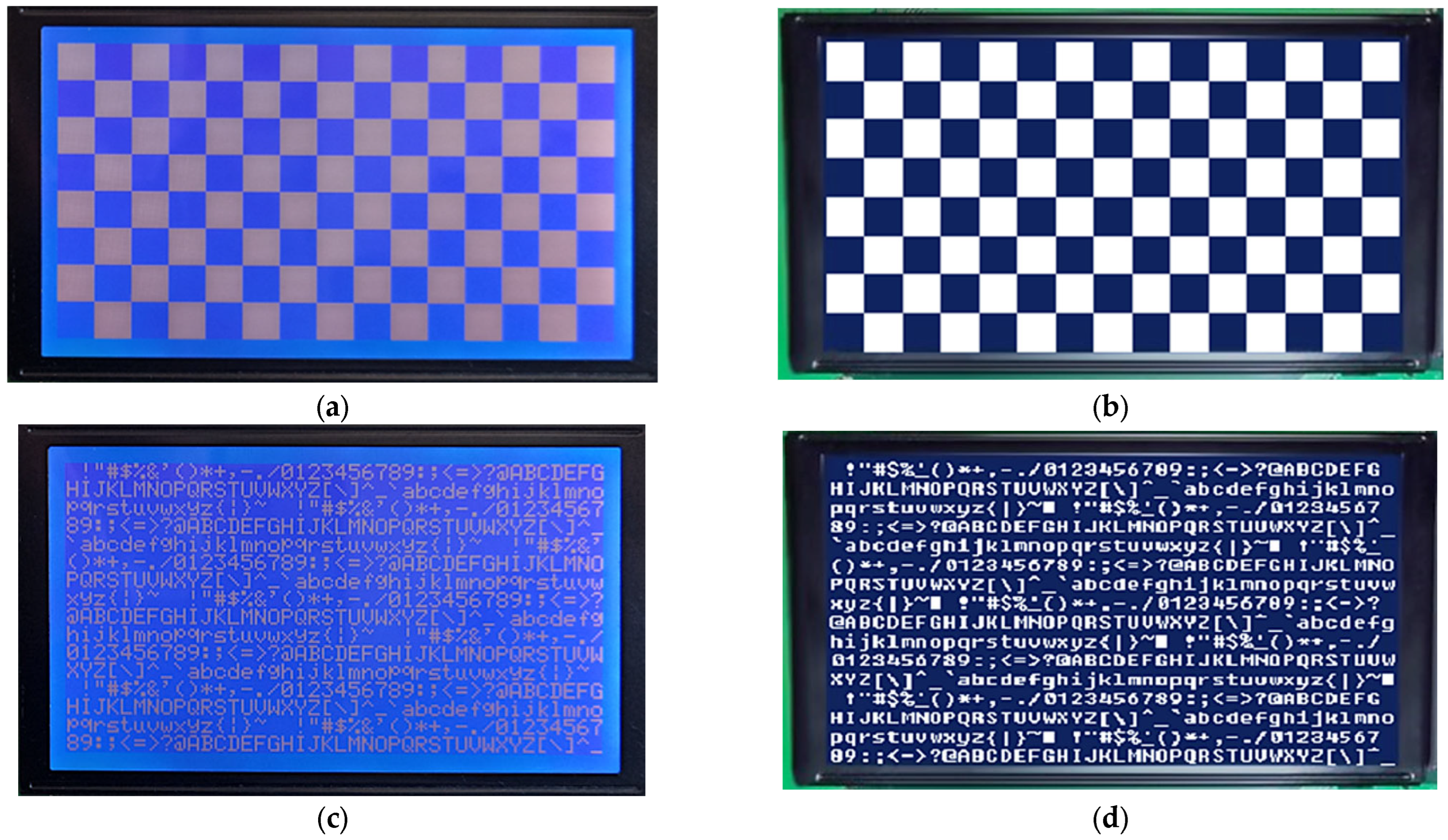
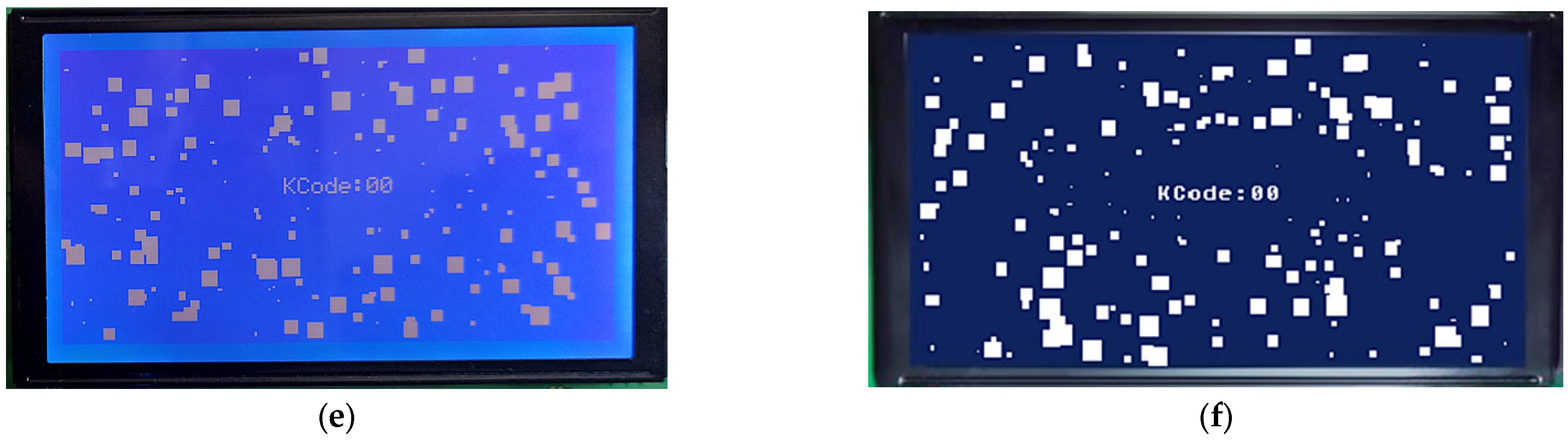
4.4. Simulators Tests Results
5. Discussion
- -
- basic data types that can vary for used platform compilers: a safe approach should consider using types defined in stdint header;
- -
- memory layout, which is typically one continuous space for simulator and for embedded system can be fragmented among many blocks; this issue can be solved using a proper linker script;
- -
- timings of peripherals operation and program execution in the target platform; this will be different on both platforms, so properly designed software cannot rely on this behavior directly in the Application Layer;
- -
- a lack of common synchronization mechanism for both platforms, between the main program and timer handlers, so for simplicity and rapid development of the simulator, there is no synchronization provided, and to avoid inconsistent access to shared resources, they should be accessed atomically;
- -
- a risk of using libraries on a virtual simulator platform that are not supported in the embedded system, which can be a serious mistake and force a redesign of software developed purely in the virtual simulator;
- -
- Non-typical behavior of an embedded application running in a virtual simulator that is forced to close, so this should be covered by the software to make a clean exit from an application that will be unnecessary in a real device;
- -
- using Microsoft Windows as a platform for a virtual simulator can lead to potential issues with constant time-period requirements for embedded-timer implementation; this is caused by the non-deterministic nature of the Microsoft Windows operation system.
6. Conclusions
Author Contributions
Funding
Institutional Review Board Statement
Informed Consent Statement
Data Availability Statement
Conflicts of Interest
References
- Real-Time Embedded Systems; MDPI: Basel, Switzerland, 2018; ISBN 978-3-03897-510-6.
- De Micco, L.; Vargas, F.L.; Fierens, P.I. A Literature Review on Embedded Systems. IEEE Lat. Am. Trans. 2020, 18, 188–205. [Google Scholar] [CrossRef]
- Edwards, S.; Lavagno, L.; Lee, E.A.; Sangiovanni-Vincentelli, A. Design of embedded systems: Formal models, validation, and synthesis. Proc. IEEE 1997, 85, 366–389. [Google Scholar] [CrossRef]
- Morison, G.; Barrie, P. An integrated approach to teaching embedded systems early in the curriculum-Flip flops to PONG. In Proceedings of the EDERC 2012 5th European DSP Education and Research Conference, Amsterdam, The Netherlands, 13–14 September 2012; pp. 169–172. [Google Scholar] [CrossRef]
- McLoughlin, I.; Aendenroomer, A. Linux as a teaching aid for embedded systems. In Proceedings of the 2007 International Conference on Parallel and Distributed Systems—ICPADS, Hsinchu, Taiwan, 5–7 December 2007; Volume 2. [Google Scholar] [CrossRef]
- Hollstein, T.; Reinsalu, U.; Leier, M. Motivation-driven learning processes at the example of embedded systems. In Proceedings of the EWME 2014: The 10th European Workshop on Microelectronics Education, Tallinn, Estonia, 14–16 May 2014; pp. 3–6. [Google Scholar] [CrossRef]
- Sharad, S.; Muecke, K. Teaching complete embedded systems design process with graphical system design methodologies. In Proceedings of the International Conference Parallel and Distributed Systems—ICPADS, Hsinchu, Taiwan, 5–7 December 2007; Volume 2, pp. 9–14. [Google Scholar] [CrossRef]
- Yang, K.C.; Chang, Y.T.; Wu, C.M.; Huang, C.M.; Luo, H.H. Application-oriented teaching of embedded systems. In Proceedings of the 2011 IEEE International Conference on Microelectronic Systems Education (MSE), San Diego, CA, USA, 5–6 June 2011; pp. 118–121. [Google Scholar] [CrossRef]
- Liang, R. Practical Teaching Reform of ARM Embedded Technology Based on OBE Concept for Applied Undergraduates. In Proceedings of the 2021 2nd International Conference on Computers, Information Processing and Advanced Education (CIPAE 2021), Ottawa, ON, Canada, 25–27 May 2021; pp. 90–92. [Google Scholar] [CrossRef]
- Rankovska, V. Innovative Approaches in Teaching Embedded Systems. The Smart Home Project. In Proceedings of the 12th National Conference with International Participation (ELECTRONICA), Sofia, Bulgaria, 27–28 May 2021; pp. 22–25. [Google Scholar] [CrossRef]
- Schuster, H.; Wenzl, M.; Zauner, M. A framework for teaching embedded multi-core programming. In Proceedings of the 2012 IEEE/ASME 8th IEEE/ASME International Conference on Mechatronic and Embedded Systems and Applications, Suzhou, China, 8–10 July 2012; pp. 292–297. [Google Scholar] [CrossRef]
- Ping, W. Research on the embedded system teaching. In Proceedings of the 2008 International Workshop on Geoscience and Remote Sensing (Ett and Grs), Shanghai, China, 21–22 December 2008; Volume 1, pp. 19–21. [Google Scholar] [CrossRef]
- Fan, H.; Wu, X.; Ghannam, R.; Feng, Q.; Heidari, H.; Imran, M.A. Teaching Embedded Systems for Energy Harvesting Applications: A Comparison of Teaching Methods Adopted in UESTC and KTH. IEEE Access 2020, 8, 50780–50791. [Google Scholar] [CrossRef]
- Ibrahim, I.; Ali, R.; Adam, M.Z.; Elfidel, N. Embedded systems teaching approaches & challenges. In Proceedings of the 2014 IEEE 6th Conference on Engineering Education, Kuala Lumpur, Malaysia, 9–10 December 2014; pp. 34–39. [Google Scholar] [CrossRef]
- Werner, S.; Lauber, A.; Koedam, M.; Becker, J.; Sax, E.; Goossens, K. Cloud-based design and virtual prototyping environment for embedded systems. Int. J. Online Eng. 2016, 12, 52–60. [Google Scholar] [CrossRef]
- Silva, E.T.; Barcelos, D.; Wagner, F.R.; Pereira, C.E. A virtual platform for multiprocessor real-time embedded systems. In Proceedings of the 7th International Workshop on Java Technologies for Real-Time and Embedded Systems, Madrid, Spain, 23–25 September 2009; pp. 31–37. [Google Scholar] [CrossRef] [Green Version]
- Ghosh, A.; Bershteyn, M.; Casley, R.; Chien, C.; Jain, A.; Lipsie, M.; Tarrodaychik, D.; Yamamoto, O. Hardware-software co-simulator for embedded system design and debugging. In Proceedings of the Asia and South Pacific Design Automation Conference ASP-DAC, Chiba, Japan, 29 August–1 September 1995; pp. 155–164. [Google Scholar] [CrossRef]
- Cho, S.-Y. A virtual simulation package for Embedded System training and education. In Proceedings of the 2009 International Conference on Engineering Education (ICEED), Kuala Lumpur, Malaysia, 7–8 December 2009; pp. 72–76. [Google Scholar]
- Scherp, A. Software development process model and methodology for virtual laboratories. Appl. Inform. Proc. 2002. Available online: http://ansgarscherp.net/publications/pdf/C01-Scherp-SoftwareDevelopmentProcessModelAndMethodologyForVirtualLaboratories.pdf (accessed on 20 April 2022).
- Beghi, A.; Marcuzzi, F.; Martin, P.; Tinazzi, F.; Zigliotto, M. Virtual prototyping of embedded control software in mechatronic systems: A case study. Mechatronics 2017, 43, 99–111. [Google Scholar] [CrossRef]
- Xie, W.; Yang, X.; Li, F. A virtual laboratory platform and simulation software based on web. In Proceedings of the 2008 10th International Conference on Control, Automation, Robotics and Vision, Hanoi, Vietnam, 17–20 December 2008; pp. 1650–1654. [Google Scholar]
- Engblom, J. On Hardware and Hardware Models for Embedded Real-Time Systems. In IEEE Workshop on Real-Time Embedded Systems; IEEE: New York, NY, USA, 2001; Available online: https://www.engbloms.se/publications/engblom-wrtes2001.pdf (accessed on 20 April 2022).
- Han, A.H.; Hwang, Y.S.; An, Y.H.; Lee, S.J.; Chung, K.S. Virtual ARM platform for embedded system developers. In Proceedings of the ICALIP 2008—2008 International Conference on Audio, Language and Image Processing, Shanghai, China, 7–9 July 2008; pp. 586–592. [Google Scholar] [CrossRef]
- Yuan, H.; Yao, Y.; He, P. An Emulation and Context Reconstruction Tool for Embedded High-Precision Positioning System. In Proceedings of the 2016 IEEE 22nd International Conference on Embedded and Real-Time Computing Systems and Applications (RTCSA), Daegu, Korea, 17–19 August 2016; p. 107. [Google Scholar]
- Petrot, F.; Hommais, D.; Greiner, A. Cycle precise core based hardware/software system simulation with predictable event propagation. In Proceedings of the EUROMICRO 97, 23rd EUROMICRO Conference: New Frontiers of Information Technology (Cat. No.97TB100167), Budapest, Hungary, 1–4 September 1997; pp. 182–187. [Google Scholar]
- Helali Moghadam, M.; Saadatmand, M.; Borg, M.; Bohlin, M.; Lisper, B. Learning-Based Response Time Analysis in Real-Time Embedded Systems: A Simulation-Based Approach. In Proceedings of the 2018 IEEE/ACM 1st International Workshop on Software Qualities and Their Dependencies (SQUADE), Gothenburg, Sweden, 27 May–3 June 2018; pp. 21–24. [Google Scholar]
- Helmstetter, C.; Joloboff, V.; Xiao, H. SimSoC: A full system simulation software for embedded systems. In Proceedings of the 2009 IEEE International Workshop on Open-Source Software for Scientific Computation (OSSC), Guiyang, China, 18–20 September 2009; pp. 49–55. [Google Scholar] [CrossRef] [Green Version]
- Ishikawa, M.; McCune, D.J.; Saikalis, G.; Oho, S. CPU Model-Based Hardware/Software Co-design, Co-simulation and Analysis Technology for Real-Time Embedded Control Systems. In Proceedings of the 13th IEEE Real Time and Embedded Technology and Applications Symposium (RTAS′07), Bellevue, WA, USA, 3–6 April 2007; pp. 3–11. [Google Scholar]
- Moon, T.-Y.; Seo, S.-H.; Kim, J.-H.; Hwang, S.-H.; Jeon, J.W. Simulation with consideration of hardware characteristics and auto-generated code using matlab/simulink. In Proceedings of the 2007 International Conference on Control, Automation and Systems, Seoul, Korea, 17–20 October 2007; pp. 1494–1498. [Google Scholar]
- Saboori, E.; Abdi, S. Hybrid Prototyping of Multicore Embedded Systems. In Proceedings of the 2013 Design, Automation & Test in Europe Conference & Exhibition (DATE), Grenoble, France, 18–22 March 2013; pp. 1627–1630. [Google Scholar]
- Muttenthaler, F.; Wilker, S.; Sauter, T. Lean automated hardware/software integration test strategy for embedded systems. In Proceedings of the 2021 22nd IEEE International Conference on Industrial Technology (ICIT), Valencia, Spain, 10–12 March 2021; pp. 783–788. [Google Scholar]
- Nooshabadi, S.; Garside, J. Teaching embedded systems design—An international collaborative project. In Proceedings of the Frontiers in Education 35th Annual Conference, Indianopolis, IN, USA, 19–22 October 2005; Volume 2015, pp. 254–262. [Google Scholar] [CrossRef] [Green Version]
- Rodriguez-Segura, L.; Zamora-Antuñano, M.A.; Rodriguez-Resendiz, J.; Paredes-García, W.J.; Altamirano-Corro, J.A.; Cruz-Pérez, M.Á. Teaching Challenges in COVID-19 Scenery: Teams Platform-Based Student Satisfaction Approach. Sustainability 2020, 12, 7514. [Google Scholar] [CrossRef]
- Khant, S.; Patel, A. COVID19 remote engineering education: Learning of an embedded system with practical perspective. In Proceedings of the 2021 International Conference on Innovative Practices in Technology and Management (ICIPTM 2021), Noida, India, 17–19 February 2021; pp. 15–19. [Google Scholar] [CrossRef]
- Shoufan, A. Active Distance Learning of Embedded Systems. IEEE Access 2021, 9, 41104–41122. [Google Scholar] [CrossRef]
- Radecki, A.; Rybicki, T. An Accurate State Visualization of Multiplexed and PWM Fed Peripherals in the Virtual Simulators of Embedded Systems. Appl. Sci. 2022, 12, 3137. [Google Scholar] [CrossRef]
- Binns, P.; Vestal, S. Formalizing Software Architectures for Embedded Systems; Springer: Berlin/Heidelberg, Germany, 2001; pp. 451–468. ISBN 978-3-540-42673-8. [Google Scholar]
- Institute of Automatic Control, Lodz University of Technology. Available online: https://www.automatyka.p.lodz.pl/?lang=en (accessed on 19 February 2022).
- Fei, J.; Quan, H.; Yuan, D. Analysis and Comparison of Two Different Implementations of MCS-51 Compatible Microcontrollers. In Proceedings of the 2011 IEEE Ninth International Conference on Dependable, Autonomic and Secure Computing, Sydney, NSW, Australia, 12–14 December 2011; pp. 275–278. [Google Scholar]
- Mroczek, H. Microprocessor Technique; Lodz Uniwersity of Technology Press: Łódź, Poland, 2007; ISBN 978-83-7283-238-2. (In Polish) [Google Scholar]
- Microprocessor Systems Laboratory. Available online: http://ztchs.p.lodz.pl/index.php?www=SM (accessed on 20 February 2022).
- Lal, S. Bare-Metal Systems. In Real World Multicore Embedded Systems; Elsevier: Amsterdam, The Netherlands, 2013; pp. 517–560. [Google Scholar]
- Tang, S.; Chan, W.C.; Vai, M.I.; Mak, P.U. A Front-end Platform of the Network-based Intelligent Home Healthcare Embedded System. In Proceedings of the 26th Annual International Conference of the IEEE Engineering in Medicine and Biology Society, San Francisco, CA, USA, 1–5 September 2004; Volume 4, pp. 3116–3119. [Google Scholar]
- Burhan, I.; Othman, R.; Azman, A.A. Development of electro pneumatic trainer embedded with Programmable Integrated Circuit (PIC) and graphical user interface (GUI) for educational applications. In Proceedings of the 2016 IEEE International Conference on Automatic Control and Intelligent Systems (I2CACIS), Selangor, Malaysia, 22 October 2016; pp. 1–6. [Google Scholar]
- Mehta, K.; Anand, R.S. Robust front-end and back-end processing for feature extraction for Hindi speech recognition. In Proceedings of the 2010 IEEE International Conference on Computational Intelligence and Computing Research, Coimbatore, India, 28–29 December 2010; pp. 1–4. [Google Scholar]
- Eclipse CDT (C/C++ Development Tooling). Available online: https://www.eclipse.org/cdt/ (accessed on 20 April 2022).
- Raitahila, I. Software Architectures in Embedded Systems. Available online: https://www.cs.helsinki.fi/u/iivorait/Software_Architectures_in_Embedded_Systems.pdf (accessed on 20 April 2022).
- Lee, J.; Park, G.; Shin, J.; Lee, J.; Sreenan, C.; Yoo, S. SoEasy: A Software Framework for Easy Hardware Control Programming for Diverse IoT Platforms. Sensors 2018, 18, 2162. [Google Scholar] [CrossRef] [PubMed] [Green Version]
Publisher’s Note: MDPI stays neutral with regard to jurisdictional claims in published maps and institutional affiliations. |
© 2022 by the authors. Licensee MDPI, Basel, Switzerland. This article is an open access article distributed under the terms and conditions of the Creative Commons Attribution (CC BY) license (https://creativecommons.org/licenses/by/4.0/).
Share and Cite
Radecki, A.; Rybicki, T. Simulation Oriented Layer of Embedded Software Architecture for Rapid Development of Custom Embedded Systems Virtual Simulators Used in Didactics. Appl. Sci. 2022, 12, 6322. https://doi.org/10.3390/app12136322
Radecki A, Rybicki T. Simulation Oriented Layer of Embedded Software Architecture for Rapid Development of Custom Embedded Systems Virtual Simulators Used in Didactics. Applied Sciences. 2022; 12(13):6322. https://doi.org/10.3390/app12136322
Chicago/Turabian StyleRadecki, Andrzej, and Tomasz Rybicki. 2022. "Simulation Oriented Layer of Embedded Software Architecture for Rapid Development of Custom Embedded Systems Virtual Simulators Used in Didactics" Applied Sciences 12, no. 13: 6322. https://doi.org/10.3390/app12136322
APA StyleRadecki, A., & Rybicki, T. (2022). Simulation Oriented Layer of Embedded Software Architecture for Rapid Development of Custom Embedded Systems Virtual Simulators Used in Didactics. Applied Sciences, 12(13), 6322. https://doi.org/10.3390/app12136322