1. Introduction
Transportation systems are characterised by many dimensions of complexity. Transportation networks are transnational and geographically dispersed, requiring the involvement of many public and private transportation operators, infrastructure, and facility-management companies. Transportation is multimodal and intermodal, combining different travel modes that vary in scale, operational flexibility, and operational complexity. The international dimension also brings differences in compliance with local regulations, which are handled differently by local authorities, as well as language challenges.
Ideally, travellers would access the entire transportation system as a “single service” that supports trip planning and travel. Several projects have been initiated in Europe to integrate these different ecosystems and bring open platforms into the everyday lives of travellers. Many of them are supported and funded by the European Commission through Interreg and the Framework Programmes. A common goal of these efforts is data integration between the different public transport subsystems and the promotion of environmentally friendly and sustainable travel with multimodal public or zero-emission transport.
In every trip, travellers encounter the physical infrastructure that enables transportation, both in the planning phase and during the actual trip. In addition to linear infrastructures such as roads and railroads, infrastructures can be simple, such as on-street bicycle racks and parking lots; or complex, such as airports, major train stations, and ports. Physical infrastructures significantly influence travel. Their influence is especially important when travellers are unfamiliar with the places that are part of their trip, such as the locations where transportation modes are changed. Physical infrastructures also influence travel for people with disabilities. Therefore, the data-integration platforms, public transit models, and trip-planning software applications mentioned above should include physical-infrastructure models. However, data collection and integration into transportation models requires additional effort, and access to and recoding of available information.
On the other hand, the construction industry, which creates the physical infrastructure for transportation, is also seeking to digitise construction planning and processes. Although digitisation in construction lags behind other industries [
1], there are many academic efforts to introduce information and communication technology (ICT) in the industry [
2]. Various aspects and barriers that contribute to this lagging are being explored, such as technological and interoperability issues, methodological and organisational challenges, and cultural and social aspects of technology adoption. Contextual requirements and interoperability issues are particularly relevant to this study. The development of transportation models and the standardisation of data exchange, in both the construction and transportation sectors, provide the framework and define the information requirements for the construction industry. In this way, the transport sector acts as a driving force and demand for the digitisation of the construction industry.
The paper presents a concept for the integration of transportation information models used by journey planners, and platforms with information models of built transportation infrastructure as a result of the application of building information modelling (BIM). In the following sections, we explore how existing transportation systems can benefit from this integration.
Our research questions are therefore:
How can building information models be incorporated into transportation information models?
What technological solutions can be used to support information exchange between the building and transportation sectors?
1.1. Related Work
Travel information systems have been prioritised in initiatives as project development calls and given more attention by public administrations as cost-effective investments that contribute to the improvement of the quality of the offered transportation services and infrastructure as well as user-experience satisfaction. Technology is one of the backbones of the advancements that have been made in this field and of the still-ongoing ventures. This paper explores the opportunities offered by BIM as a source of physical-infrastructure data for the transportation sector. This section describes the transportation-information-modelling standards, information-exploitation strategies, and technologies associated with BIM that form the background of our work.
1.1.1. Regional Integration of Sustainable Public Transportation
In the last two decades, the European Commission funded several projects aiming at integrating public transport data and multimodal travel information [
3]. The projects pursued the development of concepts, platforms, and finally the networking of actors from several European regions. The result of these efforts are distributed solutions for multimodal travel planning and travel-information-management solutions. The latest achievements provide integrated platforms for accessing high-quality travel information, enabling door-to-door route planning across borders, operators, and modes. With such systems, travellers can easily plan their entire trip and focus on their travel needs instead of searching for relevant information in separate, disjointed information systems, even for international travel. Such systems are of particular interest to our research because trip planning typically involves locations previously unknown to travellers, or trips involve the use of complex travel infrastructure.
Two such projects under the European Common Transport Area, LinkingAlps [
4] and OJP4Danube [
5], seek to achieve integrated low-emission mobility and promote multimodality as a contribution to transport system optimisation.
The LinkingAlps project focuses on the Alpine region, where remote areas often lack infrastructure and are poorly connected to public transport. By harmonising existing regional solutions and introducing innovative approaches based on a decentralised, transnational travel planning system, the project seeks to create sustainable cross-border mobility. The main objective of the project is to promote the transition from private motorised transport to low-carbon mobility options in passenger transport.
Another European regional project, OJP4Danube, integrates cross-border and cross-organisational coordination mechanisms and improves the technical and organisational alignment of transport operators and travel information service providers in the Danube Region. The project focuses on sustainable transport modes for local and long-distance traffic. The integration and exchange of information on main railway corridors connected to regional and local networks, including waterways and bicycle paths that increase the accessibility of the network, are core concerns of the project.
The provision of an efficient operational network based on open timetabling will enable the dynamic integration of information across borders and operators. Travellers will be able to receive trip information from a distributed multimodal cross-border travel-information service. An important part of this planning is managing transfers between modes. The lack of information about the facilities and specific requirements of travellers at stops can be considered an important barrier to efficient trip planning. Knowledge of the infrastructures involved and their physical characteristics is necessary for planning the walking components of the trip. For example, inaccessibility for wheelchairs can be an insurmountable obstacle. Therefore, detailed and reliable information about the buildings and other facilities that make up infrastructures such as stations is of paramount importance.
Both aforementioned projects draw on European standards and specifications such as Transmodel [
6], NeTEx [
7], and Open API for Journey Planning [
8] as the basis for service integration and data exchange.
1.1.2. Information Standards for Public Transport Infrastructure
IFOPT—Identification of Fixed Objects in Public Transport: The IFOPT [
9] is a CEN Technical Specification that defines a reference model for the description of public transport infrastructure and a reference data model that allows the description of the main fixed objects such as airports, ports, trains and bus stations and their internal structure (entrances, equipment, facilities, rooms, and platforms). In the model, special attention is paid to accessibility requirements and provisions. The IFOPT specification was developed as an extension of a broader Transmodel standard and later incorporated into Transmodel Part 2 [
10].
The IFOPT provides a conceptual framework for the identification and description of fixed infrastructure. It is focused on public transport, including multimodal contexts operated by different operators. It supports the modelling of information at various levels of detail, such as large geographic areas or detailed characteristics of a particular location. The specification defines attributes for describing infrastructure characteristics, geographic locations, and relationships in terms of infrastructure networks.
There is a great need for information in the public transportation sector. For example, operators manage fleets of vehicles, drivers, and other staff, use ticketing systems, manage schedules, and register and publish real-time information about their services. Quality of service is highly dependent on accurate and regularly updated information about changes in service offerings, schedules, and infrastructure. In passenger transport, there are many operators and service providers whose services are interdependent and interconnected. Therefore, there is a high need for frequent data exchange among the sector’s stakeholders. The Public Transport Reference Data Model (EN 12896), “Transmodel” [
6], is a European standard that provides a common agreement on the definition of concepts used in public transport. It is a reference standard that enables and improves interoperability between all public transport operators. With the help of Transmodel, the software infrastructures of private companies, public authorities, agencies, and software providers in the sector exchange information about the network and services and can work together more efficiently.
Transmodel is divided into parts that cover different information, such as network description, schedule information and vehicle planning, operations monitoring, fare management, passenger information, driver management, and information management. This structure allows stakeholders to use parts of the model and work independently from other stakeholders focusing on their specialties, while remaining compatible with others and using the same data interpretation and structuring. The conceptualisation of the model and the structure of the physical transport infrastructures, which are now part of the Transmodel standard, were developed as a separate specification IFOPT, as mentioned above.
The NeTEx [
7] technical specification defines the XML data model for implementing the core part of Transmodel. Currently, the specification is divided into six parts, each dedicated to the public transport network-topology-interchange format, the public transport timetable-interchange format, the public transport fare-interchange format, the European Passenger Information Profile, the Alternative Transport Interchange Format (CEN/TS 16614-5:2021, to be officially published soon), and the European Passenger Information Accessibility Profile (EPIAP) (currently being defined).
1.1.3. Building Data Modelling and Public Transport Infrastructure
A BIM model is a digital representation of the physical and functional properties of an object. BIM, as the corresponding process that generates and uses the model, is a methodology that integrates information technologies, policies, and processes with the aim of bringing the advances of digitisation to the construction industry [
11]. The goal of BIM as a shared resource across a facility used throughout the project lifecycle, from conception to demolition, is to increase productivity, support decision making, reduce project costs, and increase quality [
12,
13]. The construction industry has adopted Industry Foundation Classes (IFC), a standardised digital description of the construction industry developed by BuildingSMART, for the exchange of building data [
14]. IFC provides a standardised data format and semantic description of assets for the exchange of building models. IFC has been elevated to an open international standard by ISO [
2,
15,
16]
Eadie [
17] identified lack of customer demand as a strong barrier to BIM adoption. The lack of demand is a contextual variable that is often overlooked when discussing BIM implementation and is of particular interest to our work. BIM can be successfully deployed beyond the construction and facilities management processes associated with the facility. The increasing demand for information from other sectors, such as transportation, is a major driver for the adoption of BIM beyond the architecture, engineering, and construction industries [
18].
1.1.4. Interoperability, Spaces, and Navigation
For building data modelling to become a common resource for stakeholders in building projects and beyond, various levels of interoperability should be established. At a minimum, technical and semantic interoperability must be in place to share building data [
14,
15]. The use of the IFC standard beyond the construction industry contributes to broader organisational interoperability. Applying such an approach is the goal of this work, where we seek to reuse building information models to provide transportation models with data about physical infrastructure.
In the transportation sector, navigation is a particularly important component of trip planning. In addition to the obvious task of finding appropriate routes and making transport-mode choices, more detailed navigation is often required at facilities where passengers board, alight, or change transport modes. These facilities are usually buildings or other infrastructure facilities in the built environment. The IFC models contain geometric and spatial information about the buildings and their parts. The building parts are connected to each other, and the topological relationships are stored in the model. In this work, we propose an interoperability framework that supports mapping of physical infrastructure information between BIM and Transmodel. The main goal of such interoperability is to inform navigation algorithms. Therefore, the spatial topology of the built environment is the main object of the mapping. Our proposal to bridge these two worlds is to extract the topology of the building spaces from the IFC model and translate this topology into a specification compatible with Transmodel, which in our case is the NeTEx model. The topology represents the navigation network within the building and is a common abstract model shared by the both domain-specific models. This approach is common in the harmonisation of domain-specific models in the transportation domain [
19]. Applications of BIM outside the construction sector, such as mapping BIM data to GIS, also use a similar methodology [
20]. Unique to our work is the application of the principle to achieve interoperability between construction and transportation models.
The automatic creation of navigation-data models and navigation networks from IFC is not new. Liu et al. [
21] have compiled a review of extensive previous work in this area. The research shows that the IFC-based description of indoor spaces provides enough information about spaces for the creation of navigation networks, either by using IFC directly or by developing extended data models based on the IFC schema. To fully support navigation within a fixed infrastructure, a navigation-network model should be created to cover the building space, wayfinding should be developed, and localisation methods should be available. In our research, we focused on the first task, the creation of a building-space model that provides enough information for passenger wayfinding and routing. From this abstract navigation model, we focused on the preparation of a transportation model that includes fixed infrastructure. Wayfinding and routing are not part of our work, since the Transmodel-based journey planners support the routing procedures implemented in the journey planners “on-the-fly”.
Because the IFC schema is extensive, with over 600 classes, an IFC model can contain detailed information about various aspects of a building. Much of this information is not useful for navigation. By comparing research results from different authors, Liu et al. [
21] extracted a subset of IFC classes that is sufficient for creating navigation networks. According to the authors, the most important components for indoor navigation are the rooms and building elements such as walls, doors, and windows that define the connection between rooms. Based on these elements, information can be obtained and represented in navigation models.
In general, there are two approaches or methods for creating navigation models. Since the topological relationships between building parts and spaces are available in the IFC model, this information can be used to create navigation networks. The second approach does not use the topological relationships in the IFC data and creates navigation networks from a pure building geometry. In our work, we followed the first approach.
Slug and Ślusarczyk [
22] proposed an algorithm to extract a graph representing the spatial layout of a building and its topology from IFC model. The authors effectively extract information about the building from the IFC model using the topological relationships stored in the model. Besides identifying and connecting spaces, the algorithm can retrieve additional nonspatial features of the extracted paths and spaces, such as accessibility features for different types of users. This information can be efficiently used for navigation purposes, and to construct navigation networks from the IFC.
2. Materials and Methods
The process of converting BIM to Transmodel involves several steps (
Figure 1). First, the spaces and paths are extracted from IFC using topological relationships from the model. The extracted spaces are registered as nodes, and passages such as doors, stairs, and openings represent relationships between nodes in the graph of the building layout.
When the navigation graph is created, a mapping to a Fixed-Object Model follows. The mapping presented here is conceptual. IFC provides a conceptual schema and a physical format to store data in files using the schema. These can be IFC-STEP files, IFC-XML files, JSON format, etc. From these files, the data is read, parsed, and processed. Finally, the data should be converted from the abstract navigation model to Transmodel entities. The Transmodel itself does not contain specifications for encoding the data into physical files. To encode the data, a standardised schema such as NeTEx could be used to write the final model to the NeTEx XML file, and this is approach used in this work.
2.1. Extraction of Navigation Networks
Extraction and generation of navigation networks requires a method for locating and retrieving networks, followed by a method for storing the network. To generate the navigation network from IFC files, the algorithm defined by Slug and Ślusarczyk [
22] can be used. The algorithm uses IFC XML files and searches for specific entities in the building structure to identify spaces and their relationships. The algorithm relies on room definitions extracted from floor plans. Rooms are organised by spatial adjacencies, and paths between rooms are defined by openings that allow passageways. Using attribute information about entities, the algorithm extracts additional accessibility information useful for navigation. IFC entities are used as follows:
- -
IfcSpace defines the spaces and is used to add nodes to the navigation network,
- -
IfcWall defines the boundary(s) between rooms and is used to compute the room neighbourhood,
- -
IfcDoor, IfcWindow, IfcStair define the passage(s) from one room to another and are converted into edges of the navigation network.
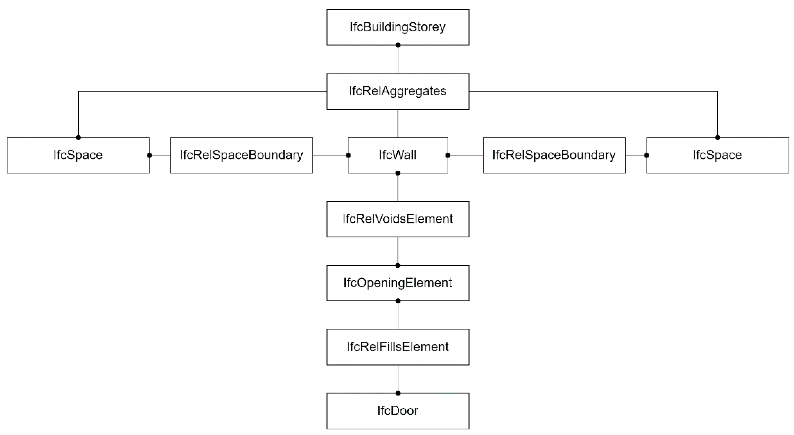
In the model, the IFC entities listed above are connected by additional IFC objects. Nodes and paths are extracted from the model using the algorithm of Slug and Ślusarczyk in the following way. Two spaces are adjacent if two
IfcSpace entities refer to the same
IfcWall or to the same
IfcWindowStandardCase using the
IfcRelSpaceBoundary relationship. Two spaces are accessible if the wall between them has an opening or door. Therefore, the
IfcWall or
IfcWindowStandardCase entity should refer to
IfcOpeningElement using the
IfcRelVoidsElement relation, or in addition, the
IfcDoor entity should refer to
IfcOpeningElement using the
IfcRelFillsElement relation (which means that the opening is filled with a door). This is an example of extraction where
IfcDoor is used as a node of the transition from room to room (an edge in the resulting navigation graph). Similarly, other “room transition” elements could be used. All rooms belonging to a floor are grouped in the IFC model by
IfcRelAggregates, which allows for the construction of a horizontal navigation graph (see
Figure 2). Each spatial entity in the IFC model inherits spatial coordinates from parent classes and the system uses
IfcLocalPlacement to extract the coordinates of nodes and links in the navigation network.
Similarly,
IfcWindow could be used as the entrance to a space or vertical connections could be extracted using
IfcSlab as space delimiter and
IfcStair as the entrance to a space. For a more detailed description of the algorithm, see the original paper [
22].
2.2. Creation of a Fixed-Object Model
The resulting navigation network is stored in Transmodel (v6) format. In Transmodel, information about transport services and infrastructure is linked. The services use scheduled stop points. For the planning and operation of the services, the physical nature of stop points is not important. However, it is important for passengers to know where the stop points are located and how to reach them. For this purpose, the Transmodel defines stop places as representations of fixed objects of infrastructure. Stop places can be used to store information about the navigation network in buildings, train stations, airports, or ports. Both stop points and stop places can represent the same location and are connected throughout the trip-planning data model. According to the Transmodel, a PLACE entity is defined as a geographic location of any type that can be specified as the origin or destination of a trip. A PLACE can have dimension 0 (a POINT), 1 (a road segment), or 2 (a ZONE). A place may contain information about its accessibility, available services, and other relevant data, such as geographic location, information about available equipment, access requirements, and internal navigation routes. Places may be related to each other, and the model provides ways to describe these connections. The complete reference network-topology data model is defined in Transmodel Part 2—Public Transport Network. The network-topology model is divided into submodels. The Network Description submodel (ND) describes elements intended for public transport operations, such as lines, routes, and stops. The submodel ND and the Tactical Planning Components Model are outside the scope of our work. The third submodel, the Fixed-Object (FO) Model, describes the fixed infrastructure and provides a detailed view of stops, including equipment, accessibility, and navigation through the places. We used the FO model for extraction of infrastructure data from IFC models.
The Fixed-Object Model can and should be connected to related objects from other submodels when available to make the most of Transmodel’s functionality. The Fixed Object Model also consists of submodels. To store the navigation network extracted from IFC data, not all entities from FO are needed. IFC might also not provide enough information to fully feed the FO model. For our purposes, entities from the
SITE submodel and the
STOP PLACE submodel were used. The subset of classes used is represented in a schema describing the site (
Figure 3).
A building or other fixed structure is represented as SITE with geographic location and possible access options. If a SITE represents a place where passengers access public transportation, SITE is considered a STOP PLACE (other options include parking lots, service points, or points of interest). The SITE could be further subdivided into SITE COMPONENTS, which could be rooms, quays, corridors, and other parts of buildings that are part of the stop space (STOP PLACE COMPONENT). ENTRANCE is also a specialisation of SITE COMPONENT and represents an entry point into a space. This is one way to encode possible horizontal movement.
SITE COMPONENTS could be combined into LEVEL(s). The LEVEL organises a building vertically. Vertical motion paths are encoded by another specialisation of SITE COMPONENT, namely EQUIPMENT PLACE. This is a placeholder for several types of EQUIPMENT (s), such as ELEVATOR, RAMP, ESCALATOR, or STAIRCASE.
For complex sites consisting of multiple buildings serving different modes, such as combinations of train station and subway, stops can be organised in a hierarchy that nests other stop places.
2.3. Correspondence between IFC and Transmodel Concepts
The network-navigation graph serves as the basis for transforming IFC classes into Fixed-Object Model concepts. Following the correspondence scheme (
Figure 4),
IfcBuilding is mapped to
STOP PLACE, which is further divided into
IfcSpaces corresponding to
STOP PLACE COMPONENTs. It should be noted that translating
IfcSpace to
STOP PLACE COMPONENT requires further parsing and concretisation when encoding the data. Since
STOP PLACE COMPONENT is an abstract class, the specialisation of each space needs to be clarified. The space could be encoded as
ACCESS SPACE,
QUAY, or
BOARDING POSITION. Network connections are relationships that link spaces together. Horizontal relationships are established by doors (
IfcDoor) and openings (
IfcOpeningElement). In Transmodel, each
STOP PLACE and
STOP PLACE COMPONENT is entered through
ENTRANCE, which is a specialisation of
SITE COMPONENT, just like a
STOP PLACE COMPONENT. However, a more comprehensive access to sites and their parts is modelled through
PLACE ACCESS EQUIPMENT, which allows for the modelling of horizontal and vertical relationships. All doors, ramps, stairs, and elevators (
IfcDoor,
IfcStair,
IfcRamp,
IfcTransportElement) represent
PLACE ACCESS EQUIPMENT. These elements are linked to
SITE COMPONENT via the class
EQUIPMENT PLACE, which enables their positioning in space.
EQUIPMENT PLACE refers to all relevant
PLACE ACCESS EQUIPMENT elements.
3. Results
The proposed information exchange between models supporting construction processes, based on the IFC standard, and models supporting the transportation sector, conceptually based on the Transmodel, is demonstrated using a train station example (
Figure 5). The station has two stop places—a bus stop place and a rail stop place—which allow transferring from bus to train and vice versa. The bus stop place has one physical stop point (quay) and the rail stop place has three physical stop points (quays as platforms 1, 2, and 3) where passengers can board and alight the public transportation.
According to the NeTEx schema, the geometry and topology of the station is described with the STOP PLACE, QUAY, and ACCESS SPACE entities contained in the SITE entity. The quays and access spaces are physical areas of different types (forecourt, booking hall, rail platform, underpass) within a stop place. Each physical area has a location, coordinates, a site level, and locations for equipment placement. Various pieces of equipment may be located within the equipment place, such as location signs, general entrance/exit signs, elevators, escalators, stairs, passenger safety equipment, crosswalks, aid station equipment, passenger information equipment, wheelchair access equipment, etc. The equipment is linked to services provided at the stop place (customer service, assistance service, complaint service, lost and found service, rental service, etc.).
Accessibility information in NeTEx supports assessment of mobility-impaired access for passengers with information requirements for accessibility constraints to stop place facilities and equipment, for example, whether a stop place has escalator-free access, is wheelchair accessible, etc. The information can be specified for all physical stop place components such as quays and access spaces.
The code in the
Appendix A shows the NeTEx XML description of the bus stop at the train station, which has a quay with a covered shelter (
Figure 1). For the quay, passenger accessibility information is also presented.
The STOP PLACE also contains a list of vertical levels. In the bus stop at the station, only a ground level is defined and referenced in the quay for the outdoor shelter equipment. Since the bus stop place has only a simple shelter, no entrances are specified. The rail stop place has one entrance (STOP PLACE ENTRANCE) to the ticket hall, one entrance to platform 1, one entrance to the underpass, and one entrance to platforms 2 and 3.
The NeTEx code snippet in
Appendix B is part of the previous full NeTEx XML description of the station (
Figure 1) and shows the stop place entrance to Platform 1 from the main ticket hall. The entrance groups objects of the place equipment, in this case a door (
ENTRANCE EQUPMENT) with its width (2.5) and height (2.5) and a ramp (
RAMP EQUIPMENT) for easy access. The entrance maintains a spatial connection (
ParentZoneRef = 2PoAd54s5oHvjLoo2LucUD) to the ticket hall, which is the associated access area. The level of the entrance is the first floor (LevelRef = 1oZ0wPs_PE8ANCPg3bIs4j.
Platforms 1 and 2, both quays, are accessible through the underpass (access space). The path from the ticket hall leads over two staircases. In NeTEx, a staircase (STAIRCASE EQUIPMENT) is modelled as follows:
The staircase contains attributes with information about the width and height in space, the number of steps, the height of a step, the presence of a handrail (used as a support when using the stairs), a riser (the vertical part of the step), and the stair shape (straight or spiral). This information is best available to passenger information systems for detailed navigation (in this case, from the ticket hall to the boarding point, platform 1 or 2).
A directed link between physical areas (QUAYs, ACCESS SPACEs, BOARDING POSITIONs, or EQUIPMENT PLACEs) is a SITE PATH LINK. An ordered sequence of SITE PATH LINKs creates a NAVIGATION PATH for the passenger to move between two places, e.g., from the bus stop quay to the station ticket hall, from the ticket hall to platform 3, and so on.
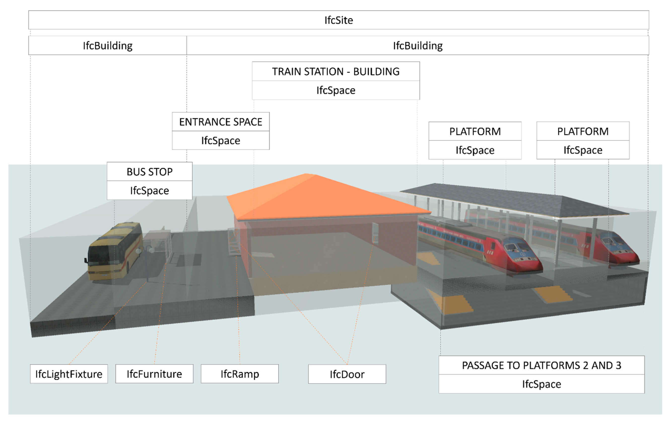
Based on the example description of the station in NeTEx, we can gain insights for the data mapping between the two information models by comparing it with a description in IFC (
Table 1), which is also shown in
Figure 6.
The conceptual model BIM (
Figure 6) was created in ArchiCAD 25 and exported in IFC version 4 (IFC4). The IFC format is the international openBIM standard.
In the model, the physical infrastructure of the station, consisting of the two buildings (stop places in NeTEx), was modelled. With the IFC4 specification, it is possible to describe geometric data and its semantics together with other properties and quantity records. Geometric objects are described as IFC objects, typically with the prefix “Ifc”, such as IfcSite. The syntax of the IFC format follows the IFC STEP Physical Format (SPF or IFC-SPF, based on the ISO standard for plain text representation of EXPRESS data models ISO 10303-21), which can be read as text. For example, the station area is encoded as follows:
        #98=IFCSITE(‘20FpTZCqJy2vhVJYtjuIce’,#12,’Main train
station’,$,$,#95,$,$,.COMPLEX.,(46,33,42,221484),(15,39,24,997061),270.,$,#84);
and the staircase is coded as:
        #35828=IFCSTAIR(‘1w5EV3smvpJ8Khm3Oeyw2E’,#12,’Staircase
1′,$,$,#35827,$,’mb:sp0005@SE1′,.NOTDEFINED.);
Both examples, site and staircase, describe top-level information of the object such as the name (‘main station’) and the location of the site (latitude in degrees (46,33,42,221484), longitude in degrees (15,39,24,997061)). The rest of the properties and quantities are broken down into several aggregations. The length of the IFC file for the complete example is almost 56,000 lines of text.
4. Discussion and Conclusions
In this work, we have proposed a concept that translates a building topology from IFC to Transmodel and aims to reuse and leverage existing building models to support the development of transportation infrastructure models. The concept proposes a method for interoperability between the two models. Thus, the benefits are twofold. Such a concept targets one of the problems in implementing BIM in the construction sector, namely the lack of demand from clients (Eadie et al. 2013). On the other hand, interoperability between the two models contributes to better trip planning. Automating this process provides a more accurate and dynamically updated source of travel infrastructure data for intermodal trip planning. Improvements in travel infrastructure models help travellers, who can obtain more accurate information not only about the main routes of their trip, but also about the details at the points of mode change. As a result, trip planning becomes more efficient and has fewer surprises.
Therefore, we present a concept for a transcoding process that extracts the topological information stored in IFC models. Following an existing algorithm proposed by Strug and Ślusarczyk [
22] for navigation-network extraction, information about spaces and passages between spaces can be obtained. The semantic information contained in the IFC models is used to transform the found topology into Transmodel objects.
Although Transmodel provides the ability to encode indoor and outdoor navigation paths at the location of a given transportation infrastructure facility, our approach does not include the encoding of this information. The navigation-network topology extracted from the IFC model could be encoded in the form of predefined navigation routes using the PATH and NODE objects in Transmodel. However, the standard discourages this approach. In complex buildings, a significant number of possible routes could be identified, and Transmodel suggests that appropriate routes should be generated “on the fly” based on the building’s network topology during the trip-planning process. Therefore, the proposed approach only involves encoding the building topology in terms of a fixed infrastructure.
The NeTEx technical specification models each Transmodel concept in XML. The core of the conceptualisation is the transportation network, schedules, and fares (the first three parts of NeTEx). In our use case, our goal was to feed the part of the transport network describing the infrastructure objects (roads, rails, stop places, and related equipment) with the infrastructure-object data modelled in IFC (version 4.0.2.1). As a first step, the mapping from IFC to NeTEx was investigated using the technical documentation and experimental modelling of the train station. Lessons learned show that NeTEx is mainly concerned with providing travel information by providing passengers with sufficient physical infrastructure data for informed access to transportation services. IFC allows for modelling of the built environment (buildings, roads, bridges, ports) with technical detail and precision beyond the needs of NeTEx (e.g., building structure and materials). Therefore, only a subset of the IFC infrastructure data can be represented in NeTEx.
Besides the infrastructure data, other nongeometrical data can be derived from IFC models and mapped to NeTEx models for transportation infrastructure services users. In our use case, the stairs (IfcStair) and the entry and exit ramp (IfcRamp) with information about required slope is modelled. Our research also highlighted mapping of data for passenger accessibility needs. IFC schema does not support accessibility information as needed by NeTEx; therefore, the mapping of the information can only be utilised through data extraction and deduction rules, whether manually or algorithmically. For example, wheelchair-enabled access can be derived from a sequence of IfcSlab and IfcRamp objects but also from the existence of the IfcTransportElement (of type elevator).
At the top level of the hierarchy, IfcSite from IFC maps to SITE frame from NeTEx, IfcBuilding maps to STOP PLACE, a QUAY within a STOPLACE maps to IfcSpace, ACCESS SPACE leading to a STOP PLACE also maps to IfcSpace, a STOP PLACE ENTRANCE to some STOP PLACE maps to IfcDoor, a RAMP EQUIPMENT leading to a STOP PLACE ENTRANCE maps to IfcRamp. NeTEx can accept the attributes of the IFC objects such as name, description, location, and dimensions (width, height, length).
The mapping principle obtained from the railroad station use case can be automated as soon as passenger information systems have access to digital building-data sets. The building data extracted from BIM (IFC) models can complement the transportation information data in NeTEx models. In the current literature, we could not find any interoperability framework for these two domains.
The proposed concept therefore suggests that it is possible to reuse the models of BIM to feed the models of transportation infrastructure, and provides the mapping. The technological basis for interoperability is based on open international standards such as IFC, Transmodel, and NeTEx, which are widely accepted in both the construction and transportation sectors. As proposed in [
19], automatic conversion of data conforming to different specifications is a key to interoperability between heterogeneous systems. In addition to harmonising data between different technologies used in transportation, our work extends existing efforts to integrate services offered by transportation agencies with new data sources that additionally support navigation.
When planning the proposed transformation, some problems also arise. Our approach relies on given IFC objects, which do not always have to be part of an IFC instance model. For example, sometimes IfcSpace objects are missing from the model because a user/modeller did not use them. Since spaces represent nodes of the navigation-network topology, in such cases it is not possible to extract a topology from the IFC using the proposed method. Similar problems can occur with stairs, ramps or door types that represent relationships between nodes. For example, the door type is important for people with disabilities, since the direction in which the door is pushed can be crucial for passage. In addition, in practise, the modelling of ramps or stairs is sometimes ambiguous (or incorrect) and it is difficult to identify such building elements and their connections to spaces from the IFC model.
Previous research has also shown that it is difficult to automatically extract vertical connections from IFC due to different approaches to modelling the building [
21]. To overcome this problem, the Strug–Slusarczy algorithm that extracts horizontal and vertical connections can be applied. The method covers well-modelled aspects of vertical-path identification. However, this remains an open question, since building modelling allows ambiguous expression of connection of building elements. At this stage, missing spatial access points representing stairs or ramps could be added manually if the transcoding software provides such a feature.
At the conceptual level presented in this paper, we focused on the most important elements of the buildings. Therefore, we have used only a small amount of available information. Usually, detailed models of fixed infrastructure provide more information about the buildings and the available equipment. Transmodel provides reference definitions for transportation infrastructure such as platforms, waiting rooms, access areas, ticket machines, seating areas, boarding areas, etc. These parts could also be available in the IFC model. However, there is no standard method for modelling and coding these details in IFC. Therefore, automatic extraction of this information is difficult, if not impossible, at this time. This remains an interesting area for future research and standardisation.


