Article

Development and Testing of Automatic Row Alignment System for Corn Harvesters

1
College of Mechanical and Electronic Engineering, Shandong Agricultural University, Tai’an 271018, China
2
Shandong Provincial Engineering Laboratory of Agricultural Equipment Intelligence, Tai’an 271018, China
3
China Railway 16th Bureau Group Corporation Limited, Beijing 100018, China
4
Shandong Wuzheng Group Corporation, Rizhao 276800, China
*
Author to whom correspondence should be addressed.
Appl. Sci. 2022, 12(12), 6221; https://doi.org/10.3390/app12126221
Submission received: 20 May 2022 / Revised: 10 June 2022 / Accepted: 16 June 2022 / Published: 18 June 2022
(This article belongs to the Section Agricultural Science and Technology)

Abstract

:
Corn harvester row alignment is a critical factor to improve harvesting quality and reduce cob drop loss. In this paper, a corn harvester automatic row alignment system is designed with a self-propelled corn combine harvester, incorporating a front-end touch row alignment mechanism of the cutting table and a harvester steering control system. Corn stalk lateral deviation from the reference row during harvesting is detected by a front-end touch-row alignment mechanism that serves as an input to the automatic alignment system. The harvester steering control system consists of Hirschmann PLC controller, electric steering wheel, steering wheel deflection angle detection device, display module and mode selection module, etc. The adaptive fuzzy PID control algorithm is used to determine the desired turning angle of the harvester steering wheel by combining with the harvester kinematic model, and the model is simulated and analyzed by Matlab/Simulink software. The automatic row alignment system was mounted on a 4LZ-8 self-propelled corn harvester for field tests, and the test results showed that the average percentage of deviation of corn stalks from the center of the row alignment cutting path within ±15 cm during the automatic row alignment process was 95.4% at harvester speeds ranging from 0 to 4.6 km/h, which could meet the requirements of the corn harvester for row alignment harvesting. The test results meet the requirements of the corn harvester for row alignment and serve as a benchmark for the research on automatic row alignment of corn harvesters.

1. Introduction

Mechanized corn harvesting is already commonplace in most of China’s maize-growing regions [1]. To increase the quality of corn harvesting, it is essential to reduce losses during harvesting. The loss of ears may be significantly reduced, and harvesting quality can be much improved, when the harvester platform is placed in opposing rows. To accomplish row harvesting, corn harvesters in China now have a low level of intelligence and depend heavily on manual steering during harvesting, which results in a high level of labor intensity for the driver, as well as an inability to guarantee harvest quality. In order to cut labor expenses, reduce harvest losses, and increase quality, an autonomous row alignment system for corn harvesters is needed.
Corn harvester cutting table has been extensively investigated by domestic and foreign researchers because of their critical role in harvesting the crop. Based on a thorough examination of corn-picking mechanism boundary conditions, Zhang et al. calculated the impact of picking loss [2]. The seed removal and cob removal models were established to determine the best combination of parameters for corn picking and harvesting. Zhang et al. designed a low-injury corn picking mechanism and verified through experiments that the primary and secondary order of influencing the damage rate of the cob was the picking roller speed, spring stiffness, and forward speed [3]. Monhollen, NS developed a corn grain loss assessment system comprised of a machine vision image system to evaluate cutter seed loss and harvest loss [4]. These studies have achieved good research on the factors influencing the loss of the cutting table and the determination of the loss rate, but most of these studies have only obtained the influence law of individual factors and the optimal combination parameters, and there is a lack of research on how the harvest quality of the cutting table can be improved and the specific measures to reduce the harvest loss of the cutting table.
Since the advent of RTK satellite positioning systems, which have been widely used for AB line navigation in agricultural machinery [5,6,7,8,9], autonomous driving and automatic navigation have become increasingly popular in the agricultural industry. In corn harvesters, however, the cutting table mechanism must always be aligned with the AB line driving mechanism. Alignment detection and body steering control are the two most important aspects of the automatic alignment system.
In terms of row perception, in 2000, Keicher developed a machine vision-based hoe guidance system capable of achieving 5.0 cm at a vehicle speed of 3.5 m/s with high system accuracy [10]. E. R. Benson developed and conducted field trials of a machine vision navigation system for a corn combine harvester [11]. The system separated the uncut crop rows from the surrounding background material, parameterized the corn rows, and calculated their position signals. Wang Chong et al. designed a new type of corn cutting table based on image recognition that can automatically align rows, collecting corn images by CCD cameras, analyzing and processing them with LabVIEW software, segmenting corn stalks in the case of natural lighting and complex farmland background, discerning the true distance between corn plants, and finally completing the automatic adjustment of cutting table row spacing [12] (Wang Chong, 2017). Automatic row alignment on corn harvesters is difficult because of the challenging working conditions of the dusty field during harvest and the numerous variables involved in the operation. Due to these challenges, visual image processing technology is unable to function well. How to accurately perceive the maize rows to be harvested is a pressing issue in automatic row alignment research that must be resolved immediately.
In terms of body steering control for automatic alignment systems, agricultural machinery is often used on the electro-hydraulic control method, motor control method [13,14].
An automatic steering wheel alignment system was developed by Zhang et al. at China Agricultural University, which used a combination of LIDAR and alignment sensor contacts to detect and change the steering wheel deflection angle [13]. For corn harvesters, Chen et al. at Shandong Agricultural Machinery Research Institute developed an autonomous alignment direction self-correction system that triggered the system via a sensing switch and also controlled the harvester travel direction using hydraulics [14]. Zhang et al. developed an electro-hydraulic circuit and integrated it into a small farm tractor’s traditional hydraulic steering circuit [15]. To achieve speed and position control of the steering, a PID controller was employed to operate the hydraulic valve. Yu et al. adopted a wheeled mobile robot as a test platform to effectively minimize the process of manually tweaking parameters in the path tracking task [16], allowing for improved driving of the controller’s DC motor.
He et al. in South China Agricultural University designed an electric steering wheel rice transplanter steering control system [17], adopted electric steering wheel as steering actuator, studied the automatic steering control of rice transplanter, constructed a model of rice transplanter steering system, and designed a nested steering control algorithm based on PID. The system offers good dynamic responsiveness and control stability, according to the research.
Through analysis, it has been determined that both electro-hydraulic control methods and motor control methods are extensively used in agricultural machinery and have been intensively investigated [18,19,20,21,22]. Consequently, there is a clear lack of research on the control method for automatic row alignment of corn harvesters, and it is necessary to design a set of control methods with high accuracy and low cost that are suitable for automatic row alignment of corn harvesters. In general, the steering fine-tuning control is implemented by altering the oil circuit of the hydraulic valve train. The advantages of electronically controlled hydraulic steering are great control precision and rapid reaction. However, its system adjustment is complicated and tough to implement in practice. The electric steering wheel can match the functional requirements of the end-effector of this study [17] because to its ease of installation, broad applicability, and manual automated switching function. Therefore, to address the aforementioned issues, this study takes the 4LZ-8 self-propelled corn harvester of Shandong Wuzheng Group as the carrier, designs an automatic alignment system with Hirschmann PLC controller as the main control unit, touching alignment mechanism as the system input, and electric steering wheel as the actuator, establishes the system kinematic analysis model, adopts adaptive fuzzy PID control algorithm, and realizes the automatic alignment system of corn The system kinematic analysis model is established, and the adaptive fuzzy PID control algorithm is used to realize the closed-loop control of the automatic alignment system of corn harvester.

2. Materials and Methods

2.1. The Overall Design Solution of the Automatic Alignment System

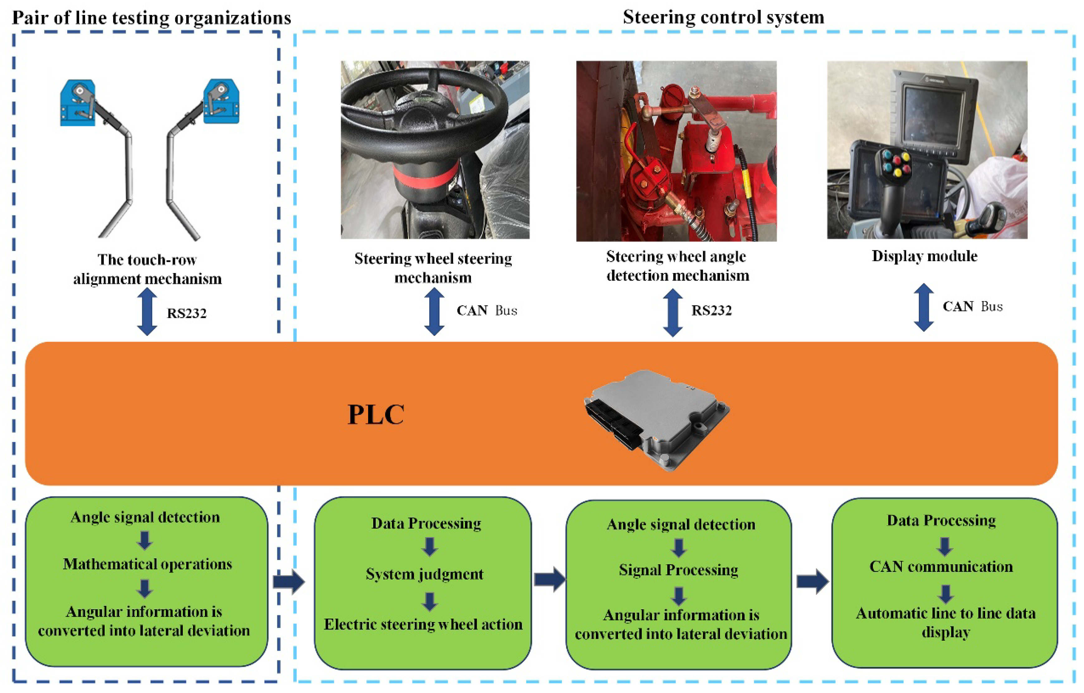
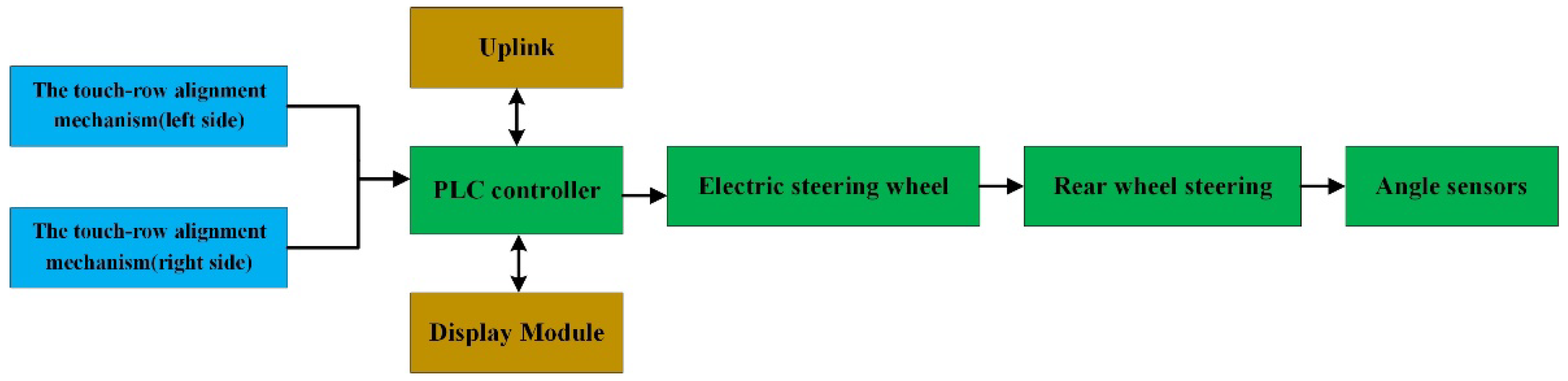
2.1.1. System Composition

The automatic row alignment system of the grain harvester consists of a mechanical touch row alignment mechanism, a Hirschmann PLC, an electric steering wheel, a rear wheel angle detection device, an LCD display and a keypad, as shown in Figure 1.
4–5 rows on the left side of the corn harvester have touch-row alignments, which provide input to the automatic alignment system by measuring the deviation from the reference row between the corn stalk and the reference row; the Hirschmann PLC is installed in the cab and is the core of the automatic alignment control system; the electric steering wheel is the actuator of the automatic alignment system and communicates with the controller through the CAN bus [23,24,25,26]. Control signals from the controller are sent to the electric steering wheel, which takes appropriate action in response to the controller’s instructions; it detects the angle of the rear wheels in real-time by installing a rear wheel angle detection device in the steering wheel (rear wheel) position; In the cab, an LCD display provides real-time information regarding the rear wheel angle and alignment, plus a button that permits automatic and manual mode selection.

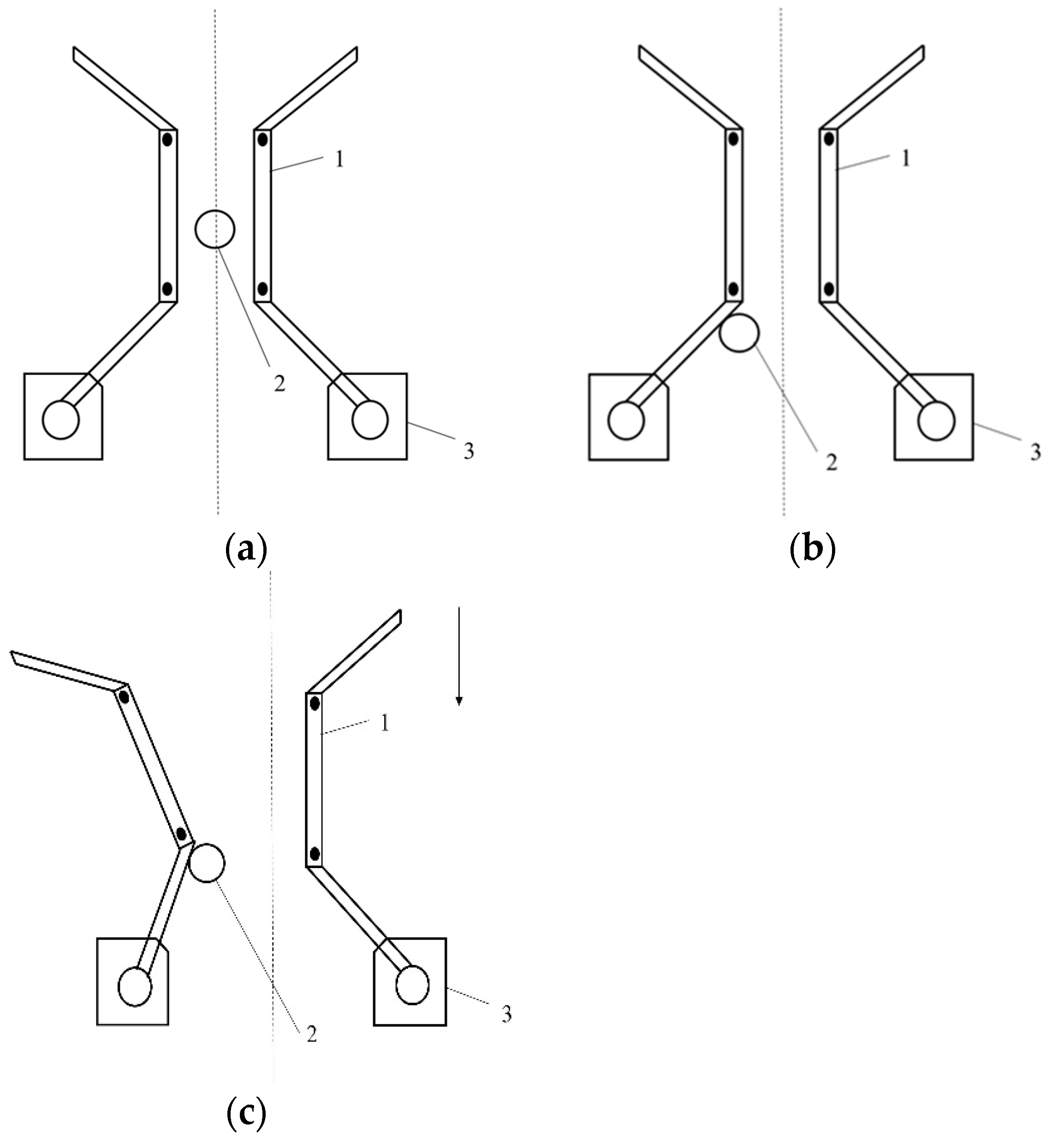
2.1.2. Working Principle

An alignment lane corresponds to the corn harvester that has the alignment mechanism installed, while a reference lane corresponds to the corn row that corresponds to the alignment lane [20,21]. The automatic alignment system of the corn harvester determines whether the alignment lane is aligned with the reference corn row by the alignment mechanism. A touch-row alignment system is shown in Figure 2. The system detects deviations from the reference row by measuring the heights of the stalks and determining whether or not to initiate automatic alignment. With the electric steering wheel, there is also a speed sensor, which transmits speed measurements to the steering wheel control unit in real time and displays the data on the LCD display through the CAN bus [27]; additionally, the steering wheel is equipped with an angle detection device that transmits information from the steering angle to the control system to provide a closed-loop control system.

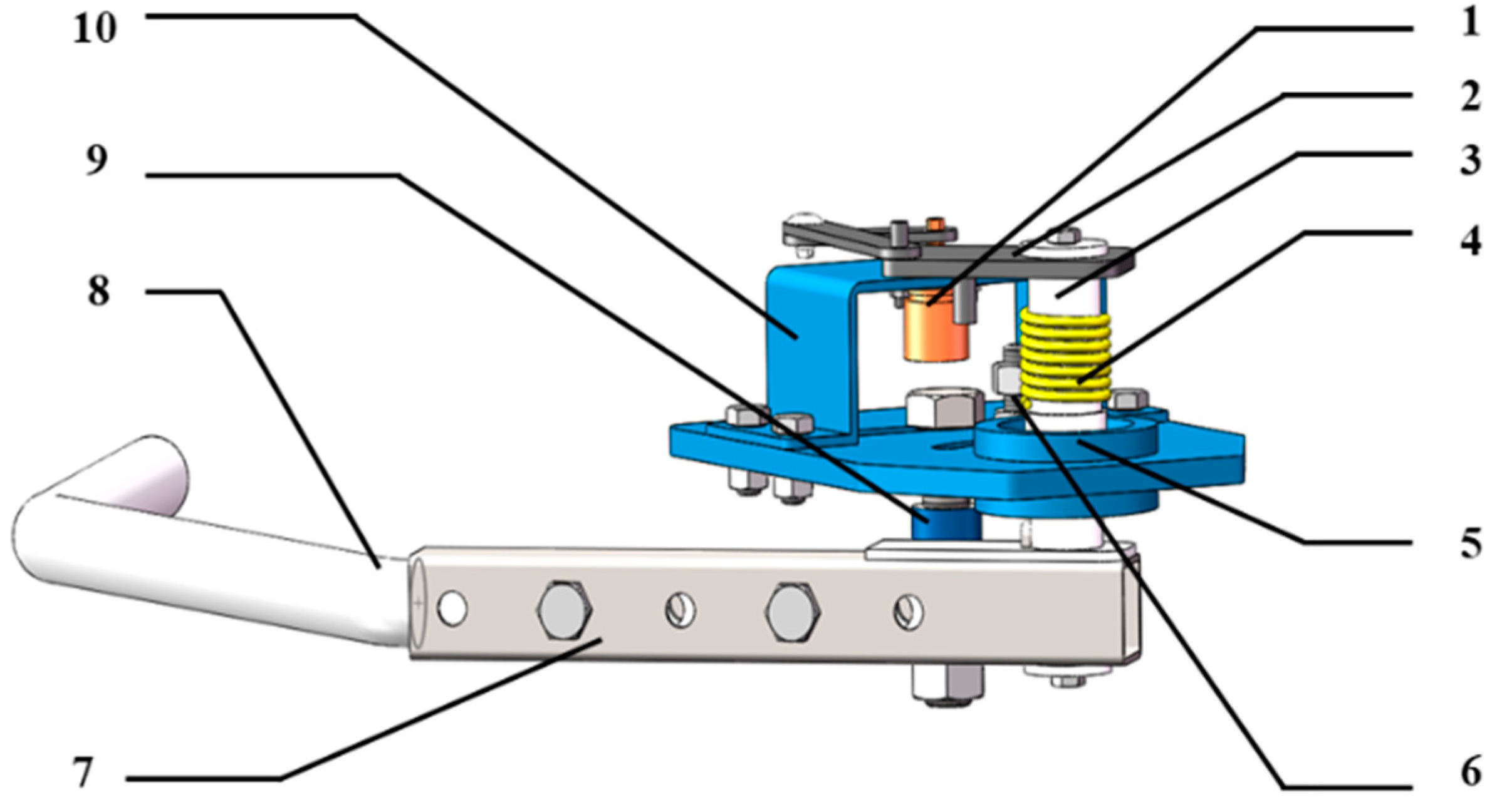
2.2. Key Component Design

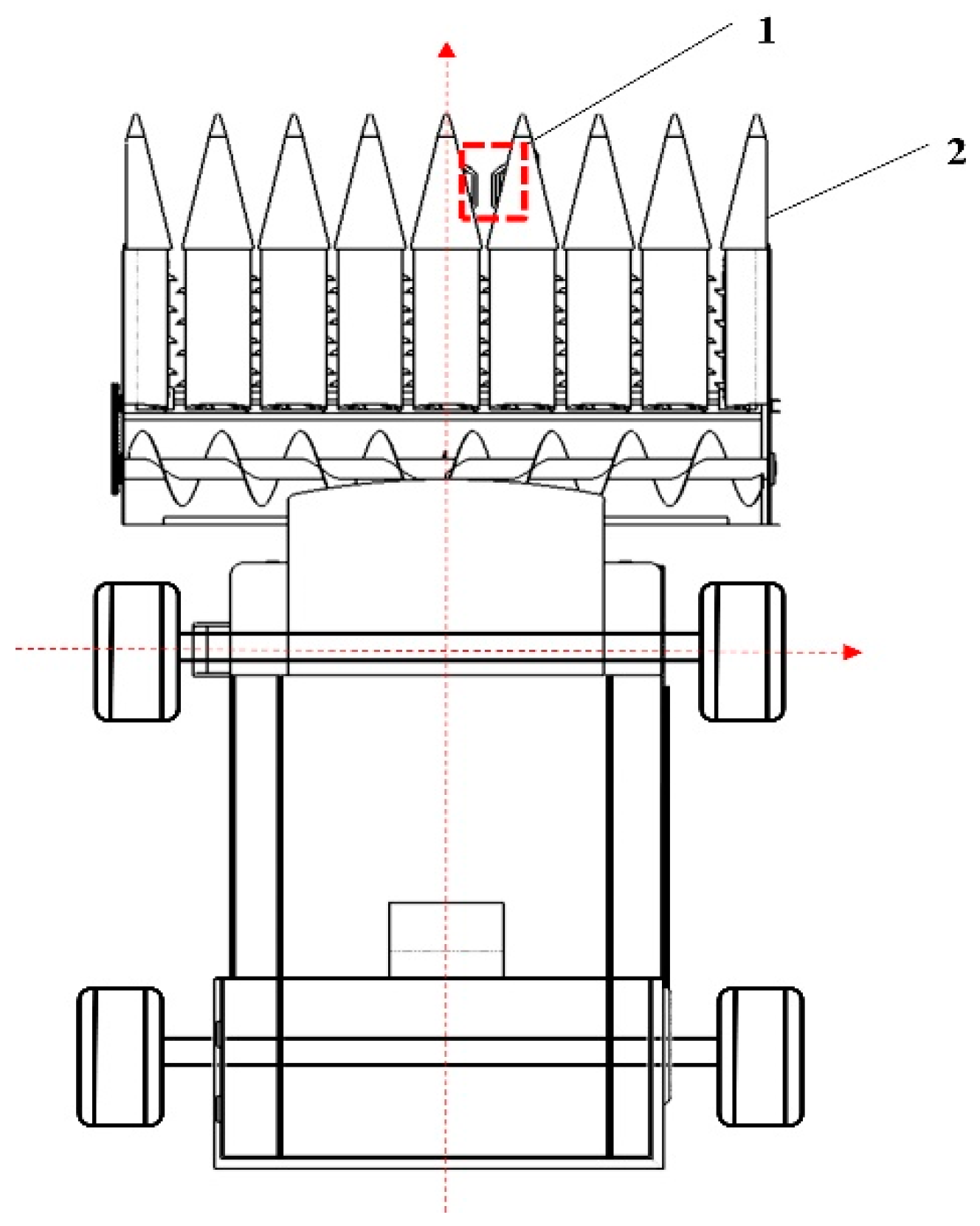
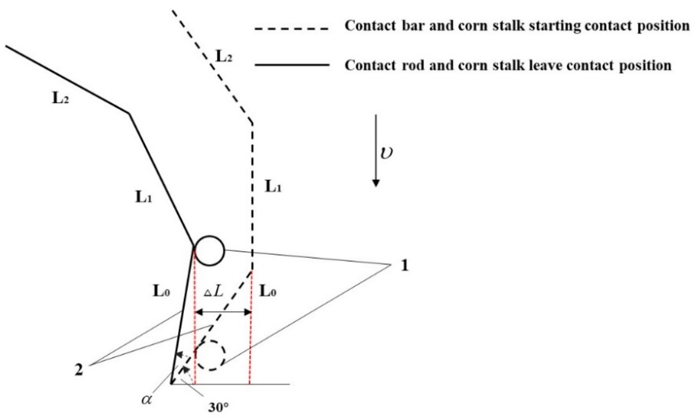
2.2.1. Touch to Line Mechanism Design

The touching alignment mechanism consists of a non-contact angle sensor, a four-rod mechanism, a rotary shaft, a reset torsion spring, bearings, a touching rod, a limit sleeve and a fixed frame, as shown in Figure 3. As shown in Table 1, the actual needs of the touch alignment mechanism are taken into consideration when designing components and performance parameters for the 4LZ-8 corn harvester.
The four-bar mechanism of the touching alignment mechanism is positioned coaxially with the crossbar of the alignment system when it is operating normally. It is the touching bar that rotates coaxially the four-bar mechanism when a corn stalk touches it; rain harvesters are guided by the deflection of the four-bar mechanism in order to steer the blade in the direction of the angle sensor; depending on the arrangement of the torsion springs, it can be assured that the touching mechanism will be reset in a timely manner following the removal of the touching bar from the stalk.
Consequently, this study has devised a touch-type alignment mechanism using a high-precision angle sensor, which can accurately estimate the size of the offset by using the change law of the output value of the angle sensor [28,29], and the structure schematic is shown in Figure 4.
A grain harvester that starts its operation is successful if the corn stalk is placed between two touching bars and no contact is established between the corn stalk and the touching bar. The angle sensor’s output does not change in this situation, and the harvester angle does not need to be changed as shown in Figure 5a. If the corn stalk collides with one of the touch bars, i.e., the corn stalk is not in the reference row, the touch bar drives the angle sensor to shift as demonstrated in Figure 5b; the harvester continues to advance until the touch bar and corn stalk are about to separate. As shown in Figure 5c, the angle output of the angle sensor achieves the maximum value at this time, and set the deflection angle of the touching rod as α.
The working principle of the touch-to-travel mechanism is shown in Figure 6, where the angle between the first and middle sections of the touch-to-travel mechanism is 120°, and the offset can be calculated according to the schematic diagram as,
Δ L = L 0 cos 30 ° L 0 cos ( 30 ° + α )
where, L0: length of the initial section of the touch bar, mm; L1: length of the middle section of the touch bar, mm; α: offset angle of the touch bar, °; L2: length of the last section of the touch bar, mm.

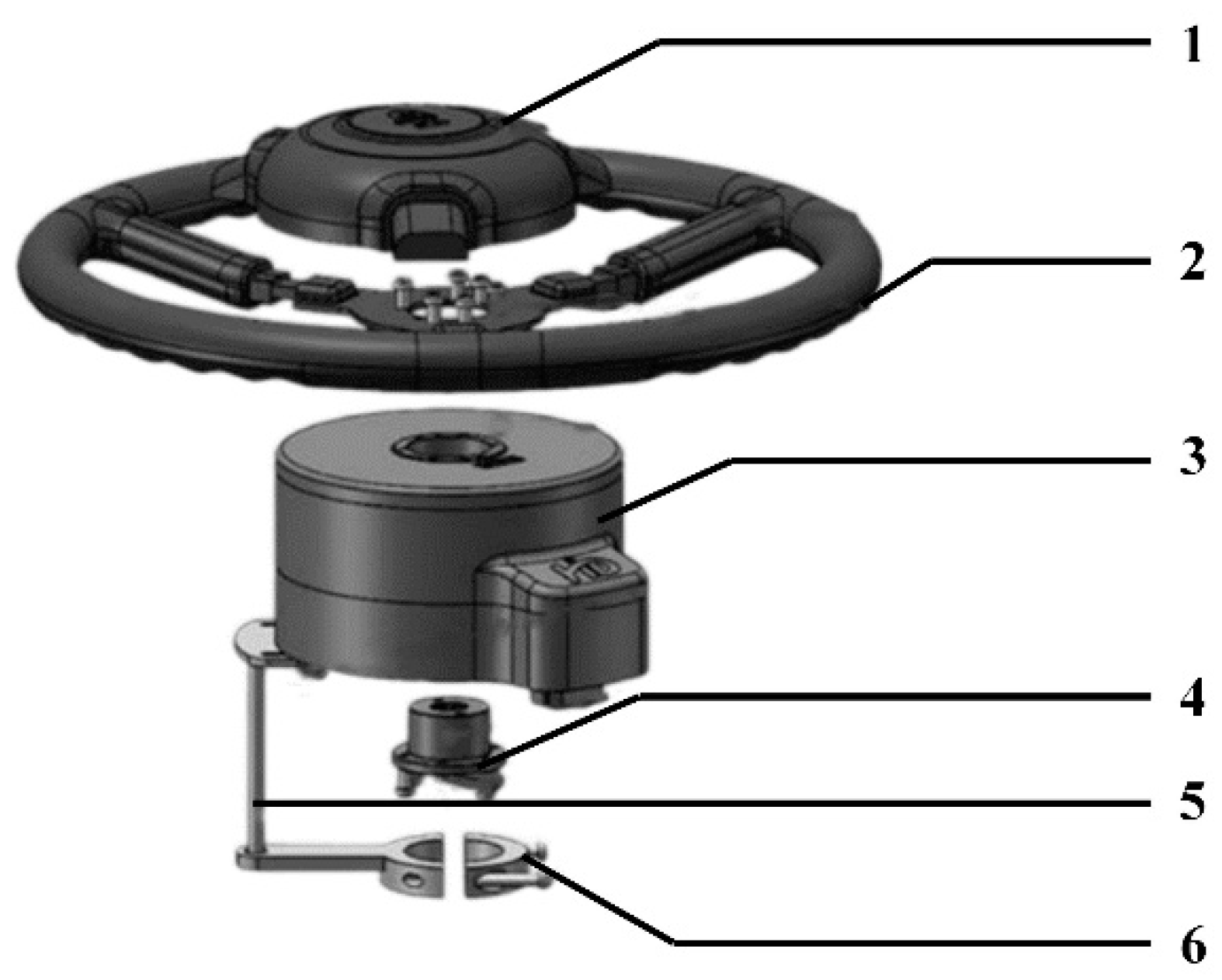
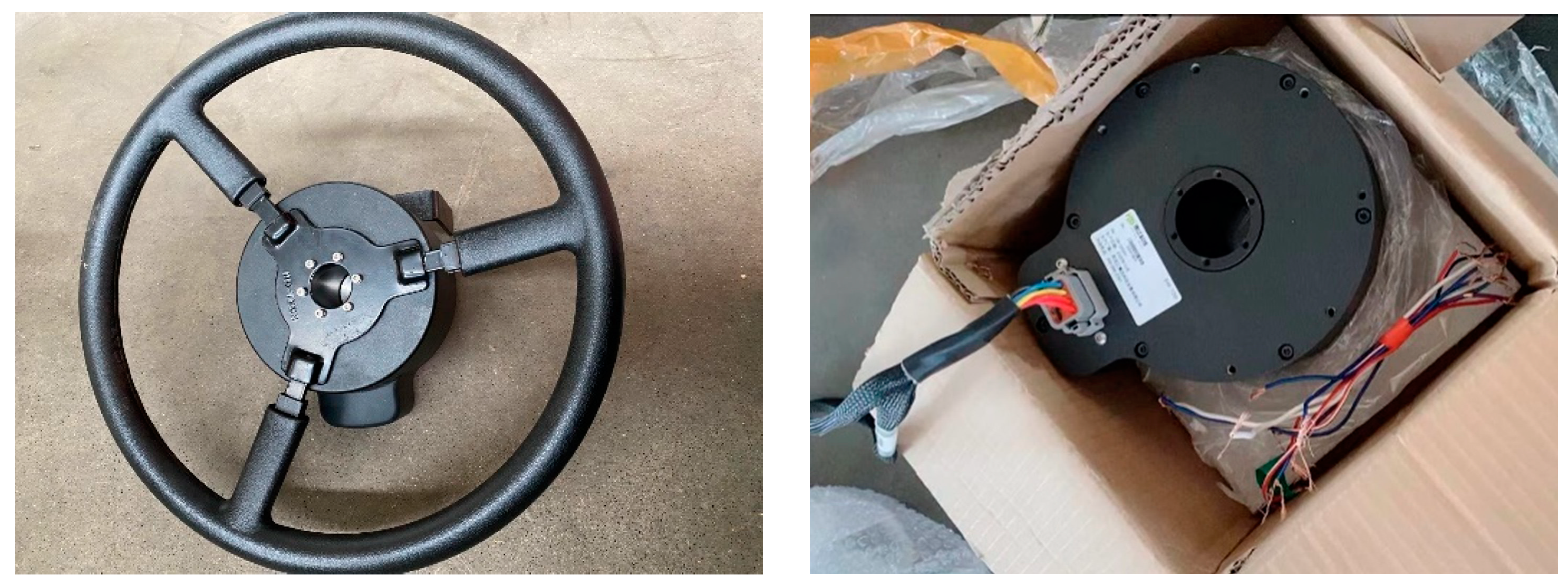
2.2.2. Electric Steering Wheel Steering Mechanism

When it comes to automated alignment systems, classic hydraulic systems and electric valves are used, but these methods have a number of disadvantages, including a high degree of complexity and a sluggish reaction time and lack of flexibility [30,31,32]. It is common for conventional automated alignment systems to control steering by changing the hydraulic system and developing an electronic hydraulic valve, but this technology has the drawbacks of complex operation, difficulties regulating the steering, poor reaction time, and limited adaptability [33]. Table 2 lists the electronic steering wheel’s most important specs, and Figure 7 depicts the whole installation.

2.3. Control System Design

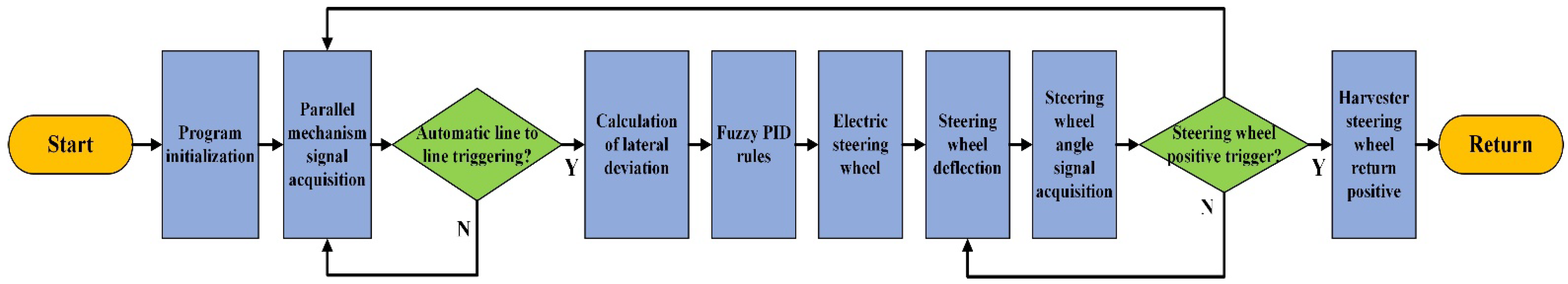
2.3.1. Automatic Line Pairing System Program Design

In this system, Hirschmann IMC series PIC controllers are used, the programming language is ST, with CODESYS as the software platform. Pressing the button of the automatic alignment system will cause the automatic alignment mode to be initiated. The program design of the automatic alignment system includes the acquisition of the angle sensor signal of the touch alignment mechanism, the electric steering wheel motion control, and the steering wheel angle sensor signal acquisition. When the automated alignment system is operating normally, the system employs a fuzzy PID control method to alter the electric steering wheel deflection angle through CAN bus and subsequently regulate the harvester’s travel direction. After the signal processing, the main control unit calculates the lateral deviation of the front-end touch mechanism through the kinematic model, and then fuzzes and defuzzes it to acquire the three coefficients for controller adjustment and the final output control quantity. Simultaneously, following the steering wheel deflection, according to the feedback angle signal from the rear wheel angle sensor to determine whether the rear wheel meets the predetermined criteria, and then complete the automatic alignment system design process as shown in Figure 8.

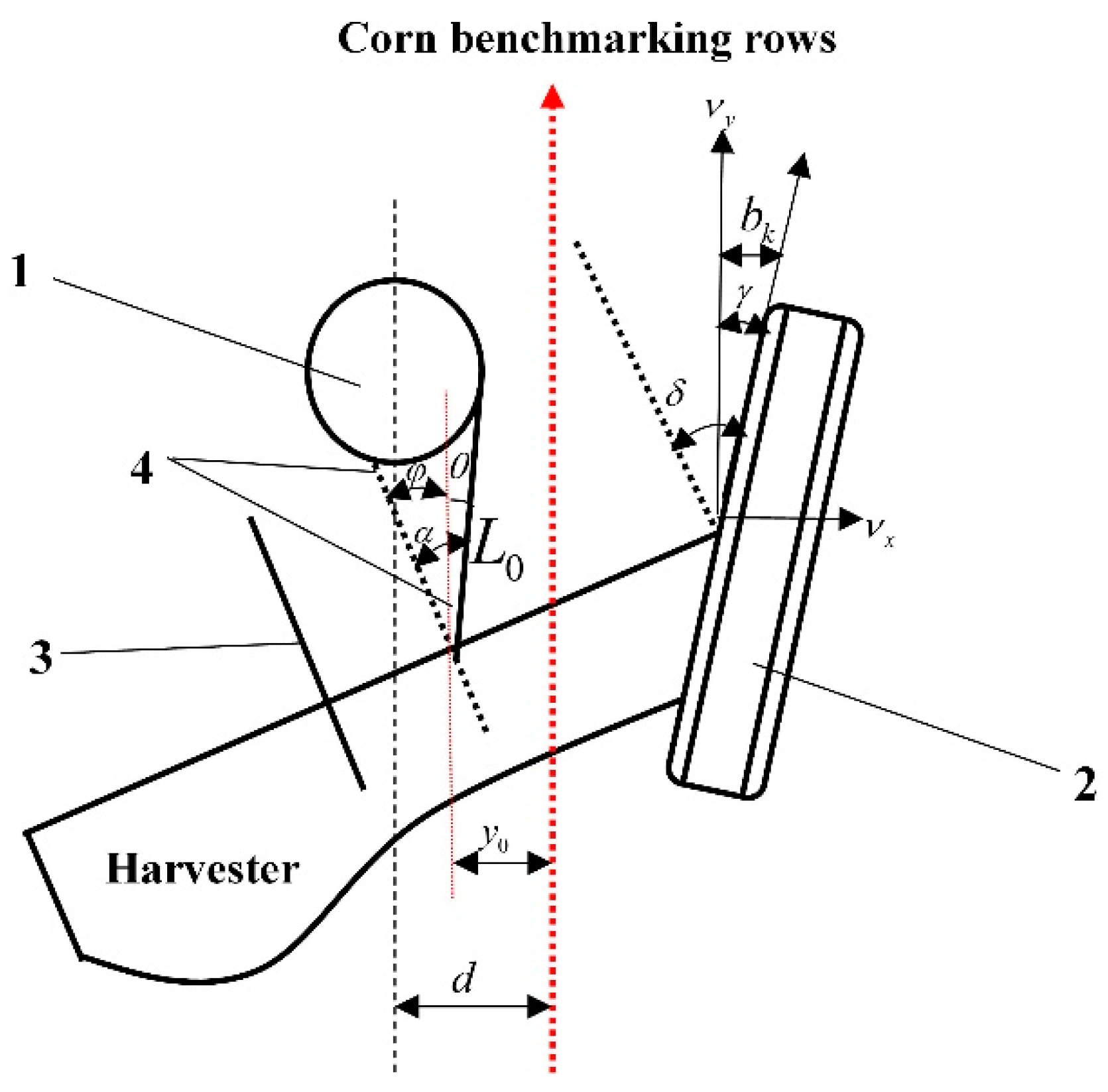
2.3.2. Kinematic Model of Body Steering Control System

Installed in the center of the harvester’s front end, the mechanical touch-to-row mechanism detects the angle between the corn plant and the reference row. To investigate the relationship between the mechanical touch-to-row mechanism and the deflection of the harvester, this section establishes a simplified model of the touch-to-row mechanism and the grain harvester during the normal harvesting process [34], taking the right mechanical touch-to-row mechanism colliding with the corn plant as an example, assuming that after starting the automatic alignment system, the deflection angle of the harvester’s touch-to-row mechanism during the harvesting process is α and the wheel deflection angle is δ. The grain harvester is simplified to a vehicle model, as shown in Figure 9.
When harvesting at a deflection angle of δ, the harvester is deemed to be operating normally because it maintains a low operating speed and the interval between predictions is generally short. A model can be calculated from this data to determine the harvester’s lateral deflection.
y 0 = | b k | + L 0 sin φ
φ = α θ
θ = arcsin ( d y 0 L 0 )
Δ L = d y 0
ν x = ν sin γ
γ = δ φ
where, y0 is the distance between the position of the mechanical touching counter-row mechanism on the right side of the corn harvester and the center offset of the corn reference row; bk is the lateral offset of the corn harvester at the current moment; S is the distance from the position of the mechanical touching counter-row mechanism on the right side of the harvester to the center of the front end; φ is the angle between the body of the corn harvester and the direction of the corn reference row; α is the deflection angle of the mechanical touching counter-row mechanism; θ is the angle between the mechanical touching counter-row mechanism and the direction of the corn reference row d is the distance between the orientation of the corn plant and the reference corn row; v is the speed of the harvester, vy is its component in the direction of the reference corn row, vx is its component in the vertical direction of the reference corn row, and the angle between v and vy is γ; δ is the deflection angle of the steering wheel.
The lateral deviation of the touch-to-travel mechanism is denoted by the Formula (1). The connection between the harvester body steering system and the preceding formula can be determined as illustrated in Equation (8).
γ = δ arcsin { d L 0 cos 30 ° + L 0 cos ( 30 ° + α ) | b k | L 0 }
b k + 1 = ν x Δ t + b k
where, bk+1 is the predicted lateral offset of the harvester at the next moment; ∆t is the sampling time. Substituting γ into vx = v × sin γ yields vx, and substituting vx into equation, bk+1 can be calculated.

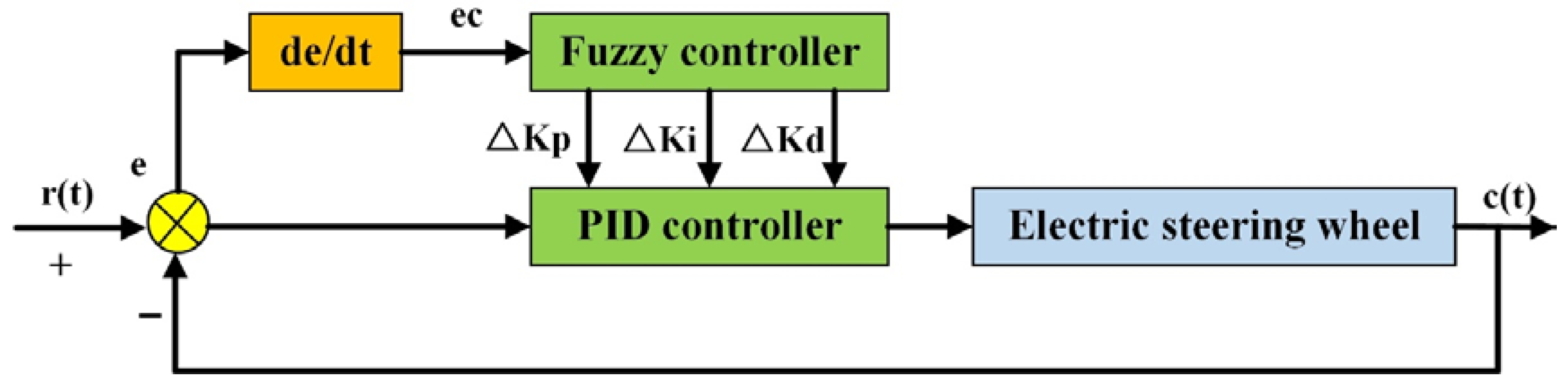
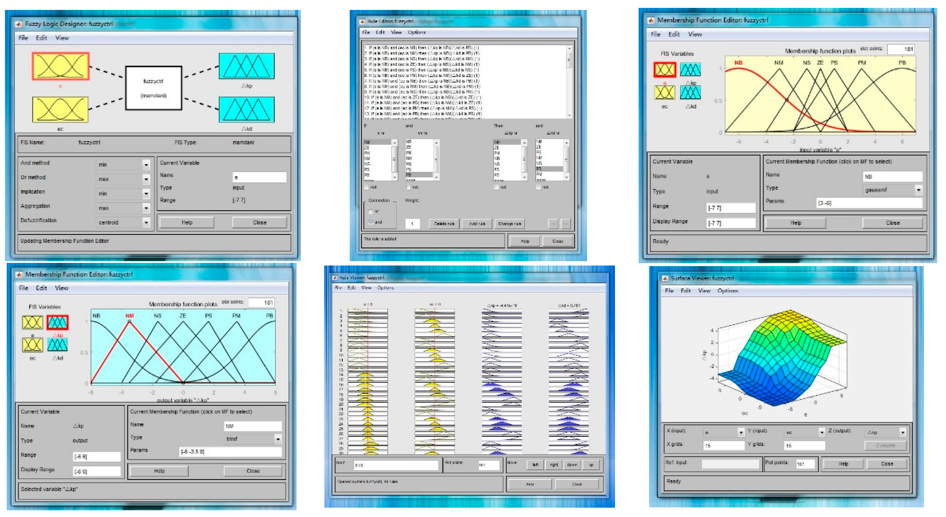
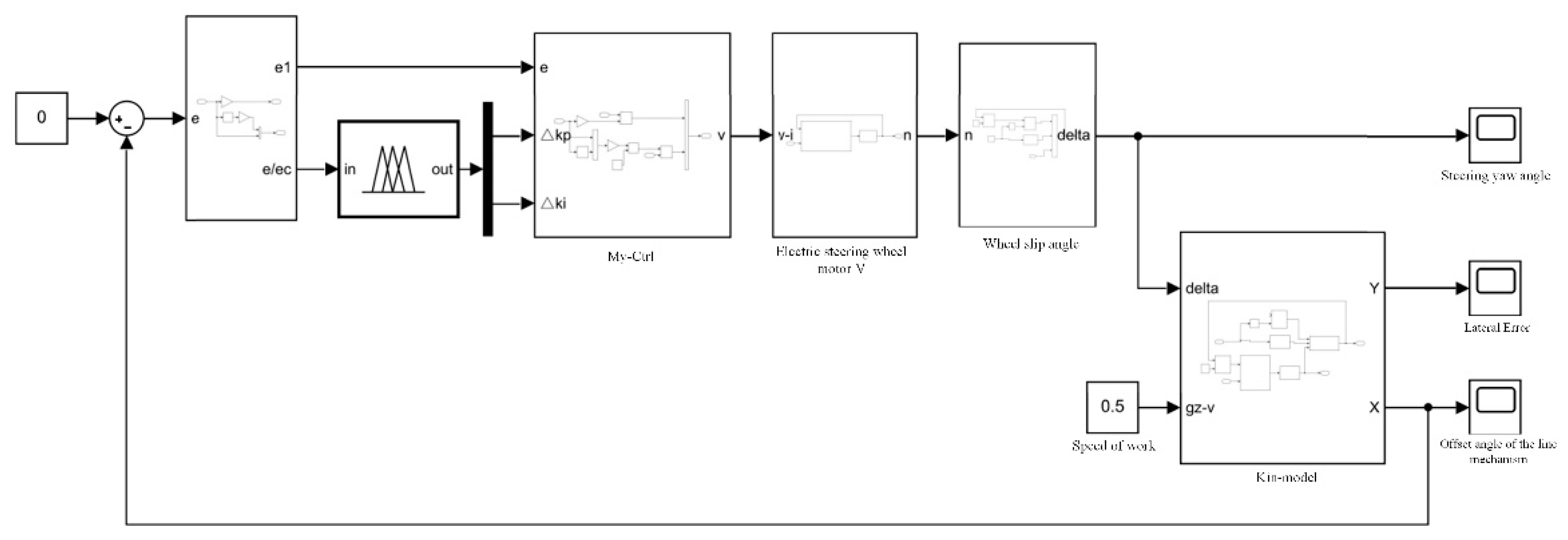
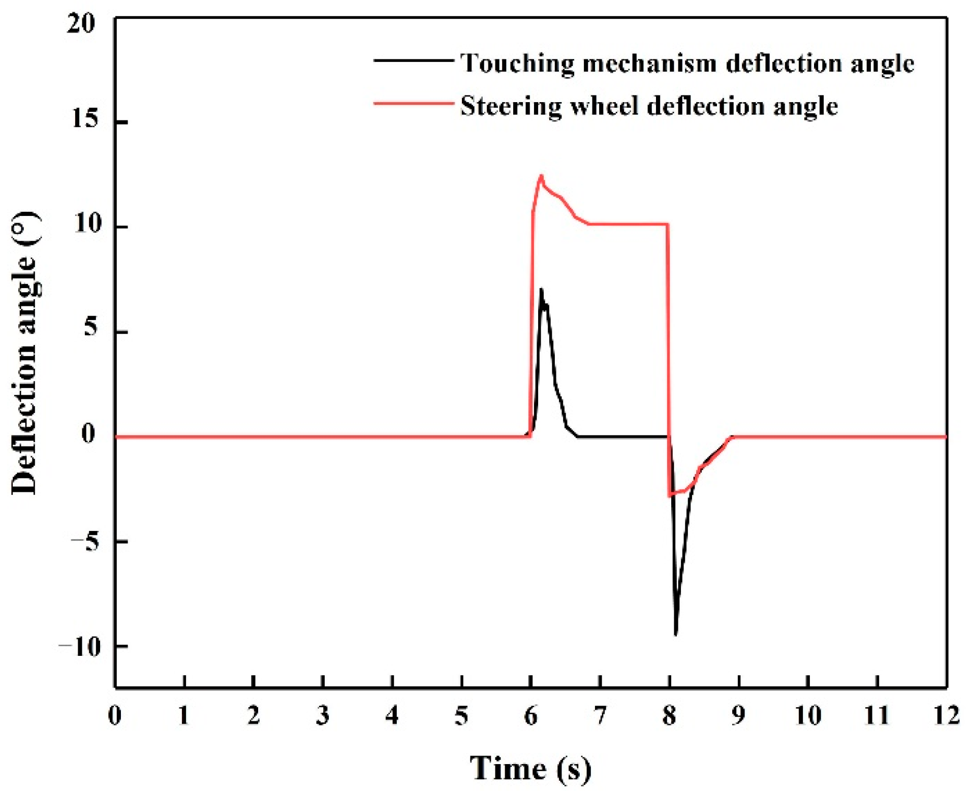
2.3.3. Fuzzy PID Control Algorithm and Matlab/Simulink Simulation

Fuzzification, fuzzy inference, and defuzzification are used to acquire real-time updated PID parameters, which are then applied to the PID controller to accomplish the control function of the controlled object [32]. PID parameters may be self-tuned by adjusting the size of the fuzzy PID control parameters based on the system’s reaction to external disturbances, thereby boosting the system’s dynamic responsiveness and its resilience. Figure 10 shows the schematic diagram of fuzzy PID control strategy.
According to the harvester driving experience, when the lateral deviation of the touching pair of rows mechanism and corn reference rows is large, it means that the harvester has a greater tendency to shift, then the harvester needs to move a greater distance in the opposite direction in a shorter time, at this time, it will increase the steering wheel angle of the harvester, so that the harvester can quickly reach the target path, in order to reduce the corn falling loss caused by heavy cutting or missing cutting; As a consequence, when the lateral deviation is large, it is imperative to prevent excessive steering wheel adjustment from overshooting the system; at the same time, when the forward speed of the harvester is large, too sharp a turn of the harvester will lead to overturning and danger, and it is also necessary to avoid excessive steering wheel angle. A fuzzy PID adaptive control system model has been developed based on the above analysis in order to test the feasibility of the proposed control strategy [35].
Firstly, the fuzzy controller is established in MATLAB’s fuzzy toolbox, the quantization domain and fuzzy subset of the input and output variables are determined, respectively [36], the affiliation function is determined, the fuzzy control rules are added, and finally the specific values at different inputs are observed through the observer simulation, as shown in Figure 11.
A fuzzy PID simulation model which includes the fuzzy control module, the PID module, the transfer function from the control system, and state update modules is developed in MATLAB/Simulink in order to verify the feasibility of the automatic alignment system, as shown in Figure 12.
A simulation test determined that turning the harvester steering wheel to the right will yield positive results, while turning to the left will yield negative results. A deflection of the right touch bar to the right will yield positive results, while a deflection of the left touch bar will yield negative results; in the reference row of corn, the stalk deflection was positive for the right side and negative for the left. Assuming the travel speed of the corn harvester is 0.5 m/s, the harvester conducts a simulation test after 6 s of travel, when the corn row is deflected to the right from the reference row and returns to the reference row at 8 s. Currently, the corn stalks are 0.2 m away from the reference row. The simulation results are shown in Figure 13. Observed from the simulation results, the automatic row alignment system was adjusted twice during the whole harvester walking process, and the steering wheel was able to adjust quickly and with a short reaction time when the touch-to-row deflected. A maximum deflection angle of 12.3° was experienced when the harvester’s right touch lever was deflected. Similarly, during normal travel, when the touch-to-row mechanism detected that the left side of the row deflected when the corn stalk returned to the reference row, the harvester deflection angle then deflected to the left, and the system made fine adjustment, while the system judged according to the signal from the steering wheel angle detection device and controlled the body back to the right, and this process shows no noticeable oscillation. Consequently, it is evident that the automated alignment system has a strong control and tracking effect, and that the system is stable, allowing the following test to be conducted.

2.4. Test Method

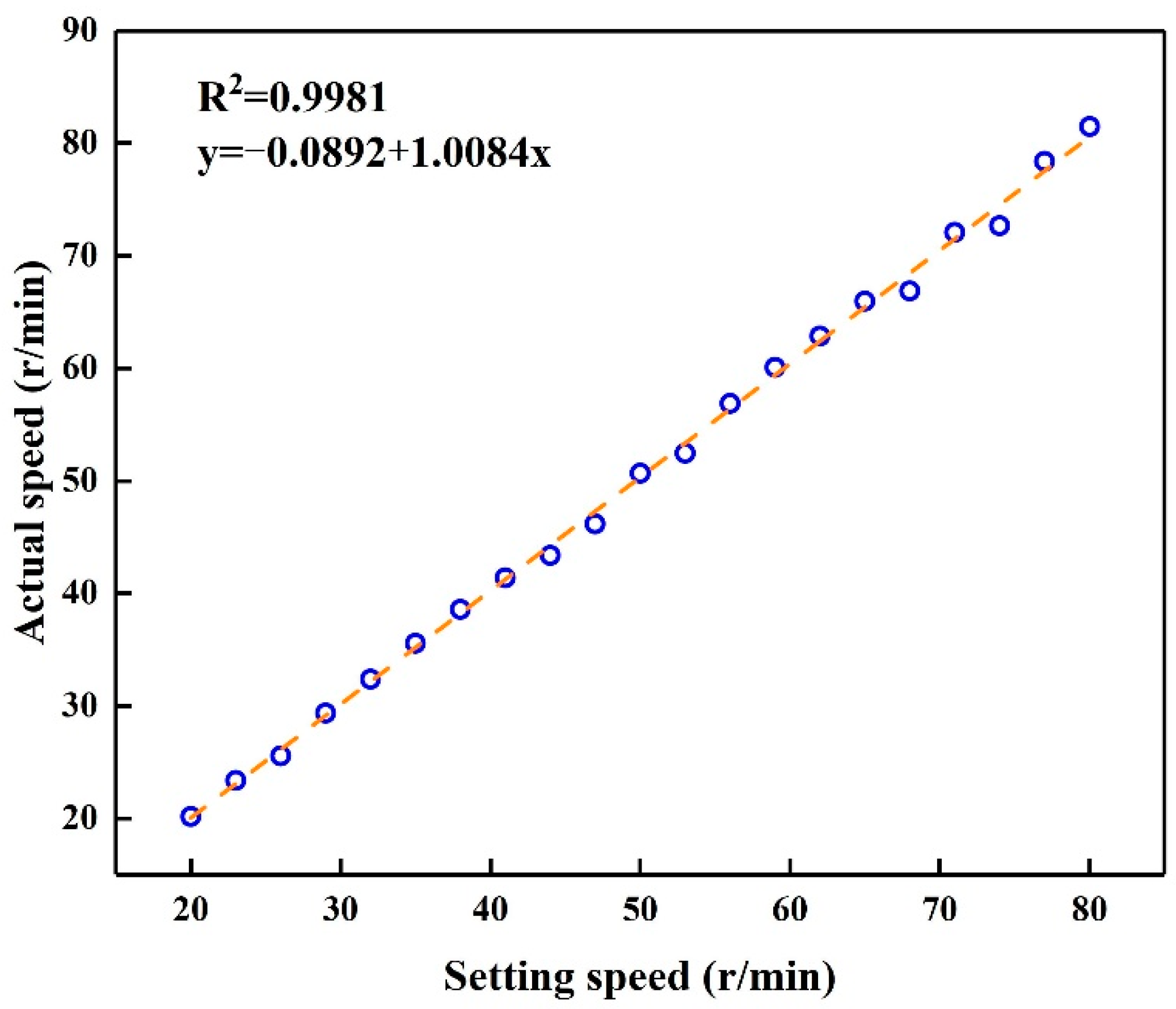
2.4.1. Electric Steering Wheel Motor Speed Test

The stability of the electric steering wheel’s performance is critical to the overall stability of the autonomous steering system. Debugging the electric steering wheel speed involves changing the controller execution programme, setting the electric steering wheel to a specific speed on the host computer, measuring the actual speed with the tachometer, and then looking at the difference in error between the set speed and the real speed.
Figure 14 shows the various pieces of equipment used throughout the testing process, including the electronic steering wheel, Hirschmann IMC3653 controller, laptop computer, and tachometer.
The electric steering wheel employed in this system is the electric steering wheel of Heilongjiang Huida Technology Development Company, the motor is a high performance PMSM motor, CAN interface [37], communication protocol is CAN2.0B protocol (extended frame). According to the relevant specifications of the communication protocol, the maximum speed of the motor is 60RPM, according to the need to send the percentage of the maximum speed can set the required speed, after completing the speed setting to start the electric steering wheel, use the tachometer to measure the actual speed of the electric steering wheel motor.

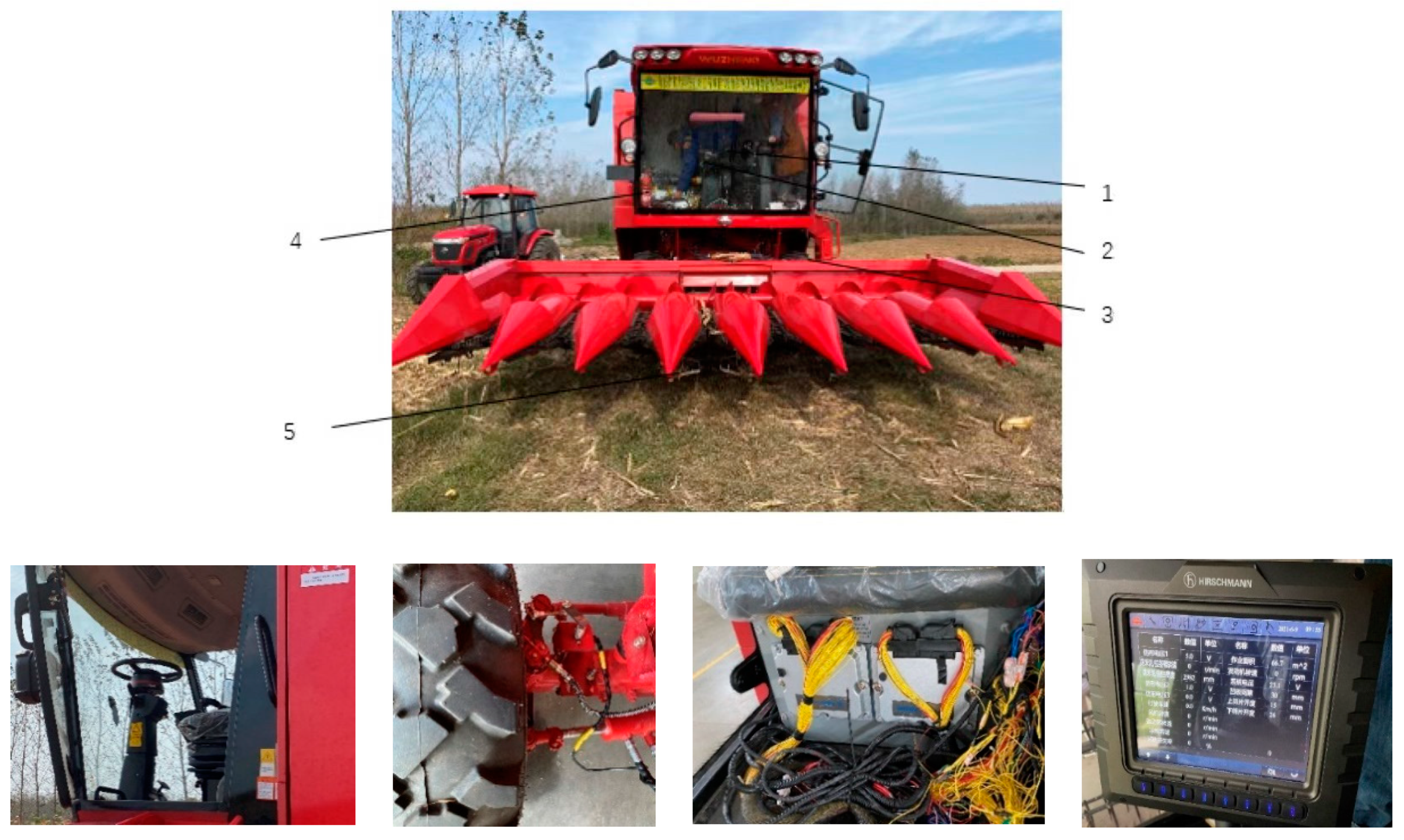
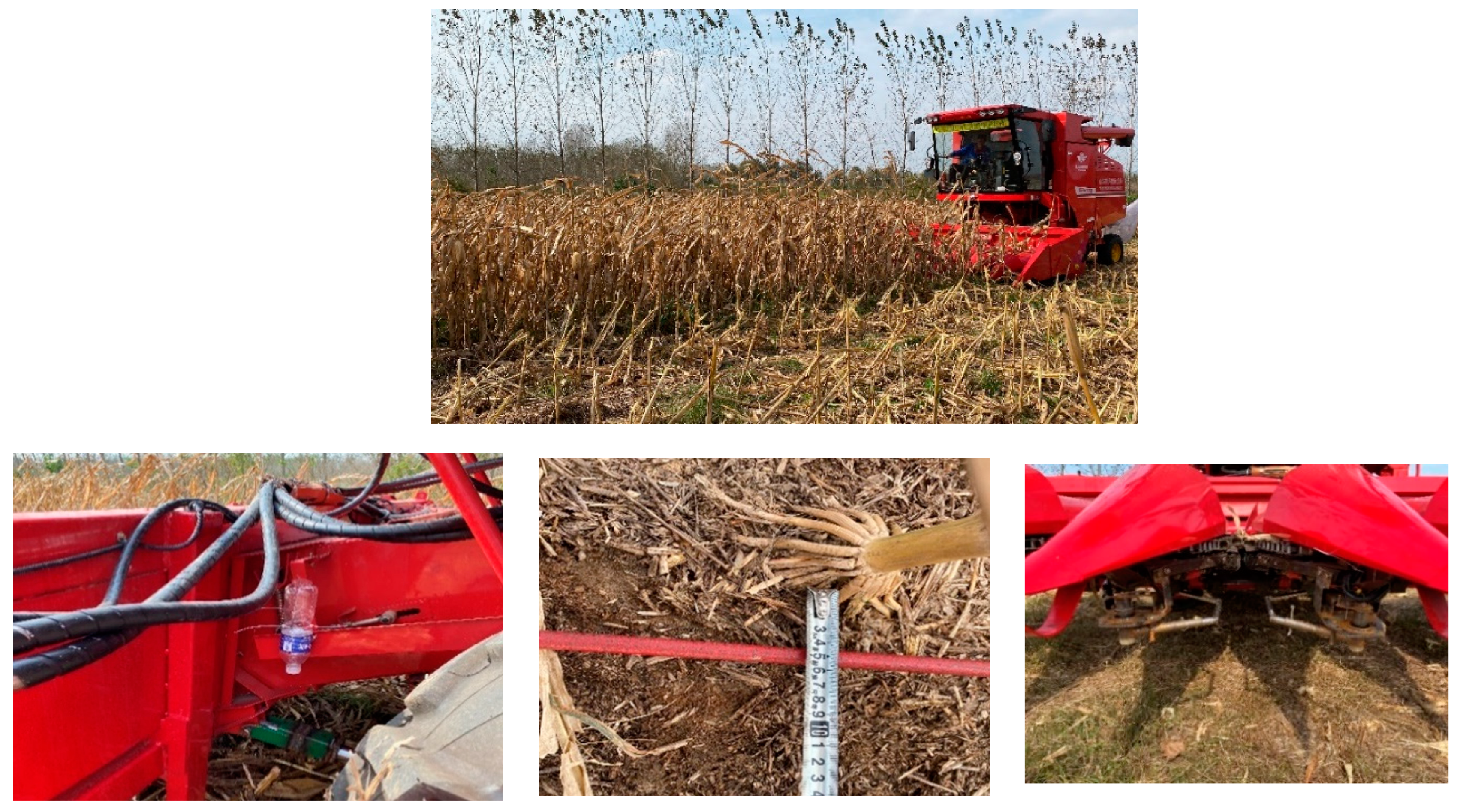
2.4.2. Field Trial of Automatic Row Alignment System

As a testing machine, the Shandong Wuzheng Group’s self-propelled corn harvester 4LZ-8 was used in order to verify the feasibility of the automatic row alignment system. In order to verify the reliability of the automatic alignment system more accurately, a three-in-one system test of the touch alignment mechanism, electric steering wheel, and rear wheel angle sensor, as well as the insertion of wooden sticks to simulate corn stalks for relevant tests were conducted in advance of the field test, and the system was further optimized according to the test results, and the improved and optimized system was used for the field test. On 20 October, 2021 in Xindianzi Village, Haiqing Town, Qingdao City, Shandong Province, a trial was conducted. The test equipment included: mechanical alignment mechanism, electric steering wheel, rear wheel angle detection device, Hirschmann IMC3654 controller, tape measure, and laptop computer, etc., as shown in Figure 15.
It was decided to divide the corn field into lengths of 20 m and to mark the length of each test unit, and 5 m were reserved for accelerating and decelerating by the harvester. Data were collected prior to the test on the deviations of the corn rows and the corn plants. During the test, the driver did not touch the steering wheel with both hands and only controlled the throttle to make the harvester reach the expected driving speed, turned on the automatic row-pairing system, and the automatic row-pairing system controlled the forward direction of the harvester to make it reach the predetermined driving speed, and detected the position of the corn plants by the touch-pairing mechanism. A drip device was installed at the horizontal position of the mechanical touch-to-row mechanism at the front of the harvester’s cutting table to track the walking trajectory of the harvester to measure the regulation effect of the control system and to measure the deflection of the harvester relative to the corn plants. For better tracking, a drip device was located within the proximity of the mechanical touch-to-row mechanism. A screenshot of this is shown in Figure 16.

3. Results and Discussion

3.1. Electric Steering Wheel Motor Test Analysis

Based on the test results, the electric steering wheel will have difficulty driving the harvester when the speed setting is less than 20 r/min, and the steering wheel should not be deflected quickly during the automatic pairwise turning process, otherwise it will be easy to roll over during the travel [13,38,39]. Therefore, the electric steering wheel control dead zone is set to [0°, 20°], [80°, 120°]. Table 3 illustrates the test results, which demonstrate that there are no differences in speed between the set and measured values within 2%.
As depicted in Figure 17, the experimental results are fitted and the R2 is 0.9981, which indicates that there is a good correlation between the set speed and the measured speed, and the fitting function y = −0.0892 + 1.0084x, which shows that the electric steering wheel has a good fit between the set value and the actual value, allowing it meet the actual operation needs.

3.2. Analysis of Automatic Row-To-Row Field Trials

A comparison of the results of automatic row alignment for the harvester at three different speeds is shown in Table 4. According to the analysis of the experimental data, with the increasing forward speed of the corn harvester [34,38,39], the deviation of the automatic alignment system adjustment trajectory and the corn reference rows showed a gradually increasing trend, and the corn harvester harvesting quality gradually decreased, which is mainly due to the increase in the forward speed of the harvester will lead to the decrease in the number of alignment adjustments at the same distance forward, which also leads to the increase in the alignment deviation, under the condition that the other conditions of the automatic alignment system remain unchanged. On the basis of the test data and the field water droplet trajectory, it can be seen that within the range of 0~5 km/h of the forward speed of the harvester, the average value of deviation of the automatic alignment system is 0.0633 m, the average value of standard deviation is 0.0668 m, the average value of percentage of deviation within ±15 cm is 95.4%, and the deviation values are all within ±30 cm, satisfying the requirements of corn harvester alignment operation. However, when the speed of the harvester exceeds 5 km/h, the deviation of automatic row alignment will increase, which is insufficient to fulfill the demand of automatic row alignment of corn, and lifting the speed restriction will be the focus of future research. Zhang et al. reported that the mean value of automatic row alignment deviation for the harvester in the range of forward speed from 0 to 5 km/h was 0.876 m, and the mean value of the percentage of deviation within ±15 cm was 83.1% [13]. Our findings outperformed theirs by 12.3%, which supports the research of a corn harvester.

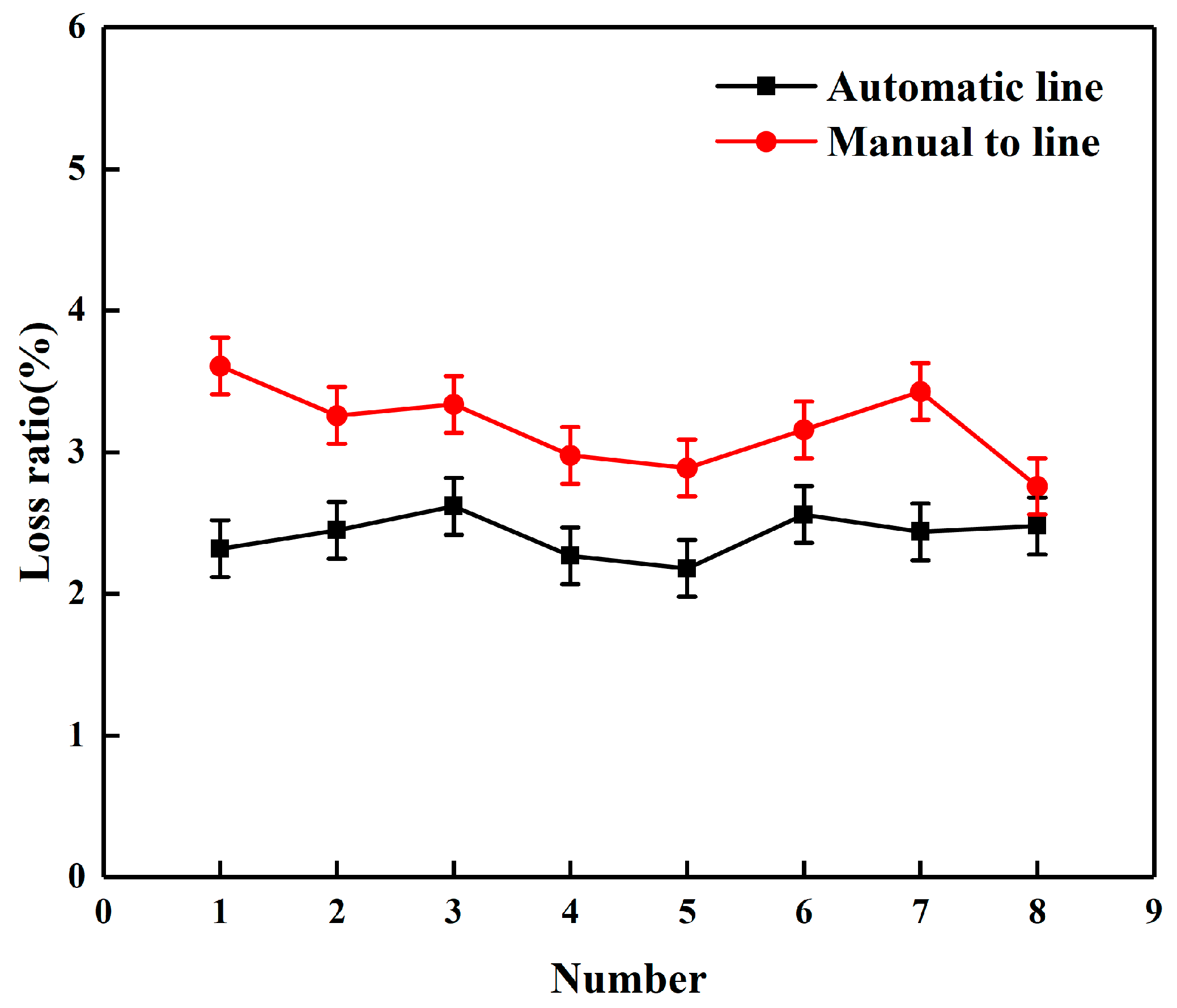
3.3. Automatic Alignment System Effect Discussion

To verify the effect of the automatic row alignment system on improving the quality of maize harvesting, a field trial was conducted in October 2021 in Rizhao, Shandong Province, on a maize seed direct harvesting machine manufactured by Wuzheng Group. The test was conducted in accordance with GB/T 5667-2007 “Production Test Methods for Agricultural Machinery”, and a plot of 30 m in length was selected for the test before the test, including a 5 m acceleration zone, a 20 m test zone and a 5 m stopping and deceleration zone [40]. Normally, the harvester passed through the acceleration zone and the test zone in turn and finally stopped at the stopping and deceleration zone.
Harvester tests were conducted in two groups, with the first group turning on the automatic alignment system, in which the driver controls the speed of the harvester only through the throttle during the harvesting process and the alignment system automatically controls the direction of travel of the harvester. The second group turned off the automatic alignment system and the driver manually altered the direction of travel of the harvester throughout the harvesting process. The driving speed of the harvester was 3.4 km/h in both test groups, and after each group of tests was completed in the harvesting process, eight 1 × 1 m2 sampling areas were selected in each test area to collect the fallen corn kernels and weigh them, and the corn kernels in the bins at the end of each test were weighed separately to calculate the loss rate of each sampling area, which was weighted to finally obtain the average loss rate using the automatic row-pairing system and without the automatic row-pairing system, respectively. Calculation of the average loss rate was carried out using Formulas (10) and (11). To acquire an average loss rate, the experiment was performed 10 times.
S 1 = 1 8 i i 10 W i W i + M 1 × 100 %
where, Wi is the amount of maize kernel drop loss in the area of the auto-pair harvest plot, i = 1, 2, 3…8, g; M1 is the mass of harvested kernels per unit area of the auto-pair harvest plot, g.
S 2 = 1 8 i i 10 W i W i + M 2 × 100 %
where, W i is the mass of maize kernel drop loss in the area of the manual pair-row harvest plot, i = 1, 2, 3… 8, g; M2 is the mass of harvested kernels per unit area of the manual pair-row harvest plot, g.
The test outcomes are illustrated in Figure 18. The loss rate of corn seeds falling from the plot harvested by the automatic row-pairing system was 2.42%, and the loss rate of corn seeds falling from the plot harvested manually was 3.18% after the automatic row-pairing system was turned off. To comply with the requirements of GB/T 21963-2020 “Maize Harvesting Machinery”, the total loss rate of maize seed direct harvesters ≤4%, which all meet the conditions. It can be concluded from the analysis that, on the one hand, the reliability of the automatic row alignment system of the corn harvester is verified; in comparison to manual row alignment, the use of the automatic row alignment system for corn harvesting reduces the loss rate of corn seeds falling by 0.76% representing a significant contribution to the reduction of the loss during corn harvesting and improving the harvesting quality [21,41,42].

4. Conclusions

The paper explores the possibility of using electric steering wheels to automatically align grain harvesters. This is a summary of the primary research work conducted in this paper.
  • In view of the current situation that the existing corn harvesters in China are primarily steered by manual operation to achieve automatic alignment, a corn harvester automatic alignment system based on touch alignment mechanism and electric steering wheel is designed, and the CAN bus is used to realize system control, resulting in a novel concept for the development of corn harvester automatic alignment.
  • The kinematic models of touch-to-row mechanism and body steering control system are built, and the automatic alignment control system of corn harvester based on adaptive fuzzy PID control is designed and simulated by Simulink in Matlab.
  • The 4LZ-8 self-propelled corn harvester serves as a carrier to achieve automatic row alignment during corn harvester harvesting, and the system is commissioned in the factory and tested in the field, respectively. The test results indicate that the electric steering wheel motor speed adjustment error is within 2%, and the deviation of corn stalk from the center of the cutting lane of the opposite row during the operation of the automatic row alignment system is 0.063 m at the mean value of deviation, which can meet the requirements of automatic row alignment harvesting of corn harvesters and is improved compared with previous reports. The adoption of automatic row alignment system for harvesting reduces the loss rate of corn kernels by 0.76% compared with manual row alignment, which is beneficial for reducing the loss of kernels in corn harvest and enhancing the harvest quality. Moreover, the deviation of automatic row alignment will progressively increase with the increase of harvester speed during the automatic row alignment harvesting process. To eliminate remove the speed limitation, we will continue to investigate innovative control strategies to lessen the deviation of the automatic row alignment system of corn harvester under high-speed operation.

Author Contributions

A.G.: conceptualization, funding acquisition. X.H.: methodology, software, data curation, writing—original draft. J.L.: validation. Z.M.: validation. Z.Z.: writing (review and editing). W.Y.: resources. All authors have read and agreed to the published version of the manuscript.

Funding

This work was sponsored by the Shandong Provincial Key Science and Technology Innovation Engineering Project (2018CXGC0217), the Shandong Provincial Natural Science Foundation (ZR2017BEE032).

Institutional Review Board Statement

Not applicable.

Informed Consent Statement

Not applicable.

Data Availability Statement

Not applicable.

Acknowledgments

We wish to thank the support of the above foundations.

Conflicts of Interest

The authors declare no conflict of interest.

References

  1. Zhang, M.; Geng, A.; Zhang, Z.; Zhang, J. Research status and development trend of intelligent monitoring system for grain harvester. J. China Agric. Chem. News 2018, 39, 85–90. [Google Scholar]
  2. Zhang, Z.; Chi, R.; Du, Y.; Pan, X.; Dong, N.; Xie, B. Experiments and modeling of mechanism analysis of maize picking loss. Int. J. Agric. Biol. Eng. 2021, 14, 9. [Google Scholar] [CrossRef]
  3. Zhang, Z.; Geng, A. Development and evaluation of low-damage maize snapping mechanism based on deformation energy conversion. J. Appl. Sci. 2021, 11, 12158. [Google Scholar] [CrossRef]
  4. Monhollen, N.S.; Shinners, K.J.; Friede, J.C.; Rocha, E.; Luck, B.L. In-field machine vision system for identifying corn kernel losses. J. Comput. Electron. Agric. 2020, 174, 105496. [Google Scholar] [CrossRef]
  5. Li, J.; Ding, X.; Deng, X. Intra-row Path Extraction and Navigation for Orchards Based on LiDAR. J. Agric. Mech. 2020, 51, 7. [Google Scholar]
  6. Miao, Z.; Tian, D.; He, C.; Li, N. Research on automatic line-to-line auxiliary driving control technology of intelligent cotton picker. J. Agric. Mech. Res. 2022, 44, 72–76. [Google Scholar]
  7. Han, K.; Hao, F.; Miao, Z.; Han, Z.; Gan, B.; Li, B.; Yu, B. Design and development of operation status monitoring system for cotton picker based on CAN. J. Farm Mach. 2019, 9, 91–97. [Google Scholar]
  8. Miao, Z.; Chu, J.; Liu, C.; Han, Z.; Gan, B.; Hao, F. Research on automatic line-to-line auxiliary driving control technology of intelligent cotton picker. J. Agric. Mech. Res. 2012, 43, 180–184. [Google Scholar]
  9. Ollis, M.; Stentz, A. First results in vision–based crop line tracking. In Proceedings of the IEEE International Conference on Robotics and Automation, Minneapolis, MN, USA, 22–28 April 1996; pp. 951–956. [Google Scholar]
  10. Keicher, R.; Seufert, H. Automatic guidance for agricultural vehicles in Europe. J. Comput. Electron. Agric. 2000, 25, 169–194. [Google Scholar] [CrossRef]
  11. Benson, E.R.; Reid, J.F.; Zhang, Q. Machine vision-based guidance system for an agricultural small-grain harvester using cut-edge detection. J. Biosyst. Eng. 2003, 86, 389–398. [Google Scholar] [CrossRef]
  12. Wang, C. Development of a New Corn Cutting Table with Automatic Row Alignment Based on Image Recognition. Ph.D. Thesis, University of Jinan, Jinan, China, 2017. [Google Scholar]
  13. Zhang, K.; Hu, Y.; Yang, L.; Zhang, D.; Cui, T.; Fan, L. Design and experiment of auto-follow row system for corn harvester. J. Agric. Mach. 2020, 51, 103–114. [Google Scholar]
  14. Chen, G.; Li, Q.; Sun, Y.; Sun, Y.; Shen, J.; He, Q. Study on automatic on-line control system of corn harvester. J. China Agric. Chem. News 2016, 37, 191–194 + 280. [Google Scholar]
  15. Zhang, Z.; Li, W.; Ma, R. Automatic steering control system research on fuzzy PID. J. Agric. Mech. Res. 2016, 38, 162–165 + 176. [Google Scholar]
  16. Yu, G.R.; Bai, K.Y.; Chen, M.C. Applications of taguchi method to fuzzy control for path tracking of a wheeled mobile robot. In Proceedings of the 2018 IEEE International Conference on Applied System Innovation (ICASI), Chiba, Japan, 13–17 April 2018. [Google Scholar]
  17. He, J.; Zhu, J.; Luo, X.; Zhang, Z.; Hu, L.; Gao, Y. Design of steering control system for rice transplanter equipped with steering wheel-like motor. J. Agric. Eng. 2019, 35, 10–17. [Google Scholar]
  18. Gao, F.; Wang, Z.; Bai, X.; Yang, L. Design of automatic row guidance device for self-propelled beet harvester. J. Agric. Mech. Res. 2020, 42, 69–76. [Google Scholar]
  19. Sharifuddin, M.; Mustaffha, S. Preliminary assessment of grain losses for paddy combine harvester in koperasi felcra seberang perak, Malaysia. IOP Conf. Ser. Earth Environ. Sci. 2021, 757, 012030. [Google Scholar] [CrossRef]
  20. Hirschmuller, H. Stereo vision in structured environments by consistent semi-global matching. In Proceedings of the IEEE Computer Society Conference on Computer Vision and Pattern Recognition (CVPR’06), New York, NY, USA, 17–22 June 2006. [Google Scholar]
  21. Li, J.; Jie, Z. Analyses of combine harvester grain loss measurement. J. Agric. Mech. Res. 2007, 12, 248–250. [Google Scholar]
  22. Zhang, X.; Liu, Z. A survey on stereo vision matching algorithms. In Proceedings of the 11th World Congress on Intelligent Control and Automation, Shenyang, China, 29 June–4 July 2014; pp. 2026–2031. [Google Scholar]
  23. Di, Z.; Cui, Z.; Zhang, H.; Jiang, W.; Zhou, J.; Zheng, Z. Design and experiment of 4YL-4 self- propelled corn grain harvester. J. Agric. Mech. Res. 2020, 42, 116–121. [Google Scholar]
  24. Dimitrov, V.; Borisova, L. Generalized scheme of fuzzy control of grain harvester in field conditions. IOP Conf. Ser. Earth Environ. Sci. 2021, 723, 032083. [Google Scholar] [CrossRef]
  25. Munack, A.; Speckmann, H. Communication technology is the backbone of precision agriculture. R. Int. Comm. Agric. Eng. 2001, 3, 1–12. [Google Scholar]
  26. Singh, M.; Singh, J.; Sharma, A. Development of a batch type yield monitoring system for grain combine harvester. J. Agric. Eng. 2011, 48, 10–16. [Google Scholar]
  27. Speckmann, H.; Jahns, G. Development and application of an agricultural BUS for data transfer. J. Comput. Electron. Agric. 1999, 23, 219–237. [Google Scholar] [CrossRef]
  28. Wang, S.; Hu, Z.; Peng, B.; Wu, H.; Gu, F.; Wang, H. Simulation of auto-follow row detection mechanism in beet harvester based on ADAMS. J. Agric. Mach. 2013, 44, 62–67. [Google Scholar]
  29. Wang, S.; Hu, Z.; Cheng, C.; Gao, X.; Gu, F.; Wu, H. Bench test and analysis on performance of autofollow row for traction sugar beet combine harvester. J. Agric. Mach. 2020, 51, 103–112 + 163. [Google Scholar]
  30. Han, K.; Zhu, Z.; Mao, E.; Song, Z.; Xie, B.; Li, M. Joint control method of speed and heading of navigation tractor based on optimal control. J. Agric. Mach. 2013, 44, 165–170. [Google Scholar]
  31. Jiang, J.; Sun, Y.; Jin, X.; Zhou, Q.; Mao, Z. CAN bus architecture design and test of combine harvester. J. Agric. Mach. 2019, 50, 93–99. [Google Scholar]
  32. Kan, Y.; Su, J.; Ding, X. Research on hydraulic control strategy of engineering vehicle based on fuzzy PID control. J. Lanzhou Coll. Arts Sci. (Nat. Sci. Ed.) 2022, 36, 78–82, 88. [Google Scholar]
  33. Lu, J.; Yin, J.; Chen, S.; Li, J.; Wang, G. Design and control research of electric steering wheel system for rice transplanter. J. Agric. Mech. Res. 2022, 44, 259–263. [Google Scholar]
  34. Miao, P.; Zuo, Z.; Mao, H.; Han, L.; Wang, T.; Wei, F.; Shi, X. Research on automatic alignment control system of electric leaf vegetable harvester. J. Agric. Mech. Res. 2022, 44, 84–89. [Google Scholar]
  35. Mo, C.; Tai, K.; Deng, S.; Duan, L. PID control parameter optimization strategy based on intelligent algorithm. Inf. Technol. Informatiz. J. 2021, 9, 222–223, 227. [Google Scholar]
  36. Zhou, Y. Research on Self-Tracking Car Based on Fuzzy-PID Control Algorithm. J. Phys. 2022, 2170, 012012. [Google Scholar] [CrossRef]
  37. Xie, B.; Yin, W.; Zhu, J. Research on intelligent monitoring system of combine harvester working condition based on CAN bus. J. Jiangsu Agric. Sci. 2012, 40, 382–386. [Google Scholar]
  38. Chen, G.; Sun, Y.; Li, Q.; He, Q.; Yong, J.; Shen, J. Study on direction self-correcting system for corn harvester automatic alignment. J. Agric. Mech. Res. 2019, 41, 191–195. [Google Scholar]
  39. Chen, G.; Zhou, P.; He, Q.; Sun, Y.; Li, Q.; Sun, Y. The research and experiment of mechanical contact navigation control system. J. Agric. Mech. Res. 2017, 39, 186–190. [Google Scholar]
  40. Li, X.; Du, Y.; Guo, J.; Mao, E. Design, simulation, and test of a new threshing cylinder for high moisture content corn. J. Appl. Sci. 2020, 10, 4925. [Google Scholar] [CrossRef]
  41. Wang, H.; Li, Y.; Qing, Y. Current status and prospect of research on combine harvester header for rape. J. IOP Conf. Ser. Earth Environ. Sci. 2021, 742, 012001. [Google Scholar] [CrossRef]
  42. Feng, H.; Gao, N.; Meng, Z.; Cheng, L.; Li, Y.; Guo, Y. Design and experiment of deep fertilizer applicator based on autonomous navigation for precise row-following. J. Agric. Mach. 2018, 49, 60–67. [Google Scholar]
Figure 1. Automatic line control system structure diagram.
Applsci 12 06221 g001
Figure 2. Working principle of automatic row alignment system for corn harvesters.
Applsci 12 06221 g002
Figure 3. Touch to travel mechanism 3D modeling (1) Angle sensor (2) Four-rod mechanism (3) Rotation shaft (4) Reset torsion spring (5) Bearing (6) Adjustable fixed torsion spring fixing bolt (7) Touch rod fixing sleeve (8) Touch rod (9) Limit sleeve (10) Fixing frame.
Applsci 12 06221 g003
Figure 4. Sketch of automatic row alignment system for corn harvesters (1) Touch pair of line mechanism (2) Cutting table.
Applsci 12 06221 g004
Figure 5. Schematic diagram of the action of the touch-to-travel mechanism (1) Touch lever (2) Corn stalk (3) Touch sensor holder. (a) Automatic row close; (b) Automatic row start; (c) Auto row ending.
Applsci 12 06221 g005
Figure 6. Automatic alignment system angle sensor offset calculation schematic (1) Corn stalk (2) Touching the middle section of the rod.
Applsci 12 06221 g006
Figure 7. Electric steering wheel installation schematic (1) Steering wheel top cover (2) Steering wheel skeleton (3) Motor (4) Adaptability flange (5) Motor bracket (6) Socket head cap screw.
Applsci 12 06221 g007
Figure 8. Control flow diagram of automatic alignment system.
Applsci 12 06221 g008
Figure 9. Harvester lateral offset modeling. (1) Corn stalk (2) Harvester steering wheels (3) Left touch lever (4) Right tough lever.
Applsci 12 06221 g009
Figure 10. Fuzzy PID controller schematic.
Applsci 12 06221 g010
Figure 11. Fuzzy controller design.
Applsci 12 06221 g011
Figure 12. Simulation model of automatic alignment system.
Applsci 12 06221 g012
Figure 13. Simulation results.
Applsci 12 06221 g013
Figure 14. Electric steering wheel motor speed debugging part of the test equipment.
Applsci 12 06221 g014
Figure 15. Experimental composition of automatic row alignment system for grain harvester (1) Power steering wheel (2) LCD display (3) Rear wheel angle sensor (4) Hirschmann IMC3653 controller (5) Touch-activated alignment mechanism.
Applsci 12 06221 g015
Figure 16. Test of automatic row alignment system for corn harvester.
Applsci 12 06221 g016
Figure 17. Electric steering wheel speed test.
Applsci 12 06221 g017
Figure 18. Corn kernels drop loss.
Applsci 12 06221 g018
Table 1. The main parameters of the touch-to-travel mechanism.
PartsModelParametersValue
Angle sensorsKALAMOYI/P3022-V-CW180Output voltage(0~5) v/(0~180)°
Touch bar retaining sleeveQ235 steel0.81740 mm
Resetting Torsion SpringsCarbon spring steelWire diameter3 mm/28 mm/6 mm
Touch BarAluminum round tubeLength150 mm/200 mm/
180 mm
Table 2. Main parameters of electric steering wheel.
ParametersValue
Operating voltage (V)9–16
Max. output torque (N.M)16
Max. speed (RPM)120
Response delay (s)<0.2
Steering error with load (°)<±5
Communication protocolCAN2.0B
Table 3. Electric steering wheel speed collection record table.
NO.Set Speed v1 (r/min)Measured Speed v2 (r/min)Relative Error (%)NO.Set Speed v1 (r/min)Measured Speed v2 (r/min)Relative Error (%)
12020.21.00115050.71.40
22323.41.73125352.50.94
32625.61.54135656.91.61
42929.41.38145960.11.52
53232.41.25156262.91.45
63535.61.71166566.01.54
73838.61.58176866.91.62
84141.40.96187172.11.55
94443.41.36197472.71.76
104746.21.70207778.41.82
Table 4. Experimental results of automatic row-to-row harvesting control system.
NO.Speed of
Advance/(km·h−1)
Deviation Values of Maize Plants from Maize Benchmark RowsDeviation (Absolute Value) of the Automatic Alignment Trajectory from the Fitted Corn Row
Maximum Values/cmMinimum Values/cmAverage Values/cmAverage Values/cmStandard Deviation/cmThe Percentage of Deviation within ±15 cm/%The Percentage of Deviation within ±30 cm/%
12.209.40−8.333.325.155.8498.8100
22.2011.06−10.563.595.765.9898.1100
33.408.25−9.634.646.436.7994.3100
43.408.04−8.323.216.256.4795.2100
54.6016.55−10.565.167.317.6592.4100
64.6014.52−12.214.087.067.3393.7100
Publisher’s Note: MDPI stays neutral with regard to jurisdictional claims in published maps and institutional affiliations.

