Abstract
Obtaining an extremely precise virtual model is decisive for the final success of prosthetic restorations on implants using CAD–CAM technology. Intraoral digital implant impression can be challenging under specific conditions (e.g., narrow spaces, lack of visibility, or subgingival margins) because sometimes the scan body does not reach an optimal supragingival level so that it can be scanned accurately. We propose an easy and quick solution, which uses an extraoral transfer device that requires minimum time and cost investment.
1. Introduction
A highly accurate virtual model is essential for the success of the final outcome of the implant-based restorations obtained using CAD–CAM (computer-aided design and computer-aided manufacturing) technology []. The performance of the intraoral digital impression technique is similar to that of the classic impression for implant restorations []; this approach has been proposed as a clinical alternative, especially for single implant-supported restorations and short-span fixed dentures (FDRs) [,].
The virtual impression technique has some challenges, which may affect the final result [,]. In favorable clinical situations or to limit the fees, implant fixed restorations typically use standard (prefabricated) abutments. When the entire workflow is digital, occlusal or cervical refinements are made by the clinician extraorally, usually using an implant analog to sustain standard abutment during the process; however, the grip is challenging to hold.
Another potential issue in the digital implant impression procedure is the subgingival margin exposure for the impression, which implies the use of a lateral gingival displacement technique or the registration of subgingival contour based on previous interim restorations [,], custom impression copings [], or healing caps [].
Another challenge of the digital implant impression technique is the need for intermediate impression accessories (i.e., scan bodies), which are sometimes available in one standard dimension for a particular prosthetic connection. They cannot be customized, unlike conventional impression copings []. The geometry of these devices has different characteristics that are specific to each manufacturer and restoration []. The accuracy of digital intraoral impressions seems to be affected by both the geometry of the scan body and the scan strategy []. In the everyday clinical practice, there are conditions when the complete insertion of a scan body is not possible (e.g., narrow spaces, angled neighboring teeth) or the gingival exposure of a scan body is limited. In some cases, the implants are inserted deep subcrestally, and, thus, the length of the scannable portion of the scan body that is screwed into the implants is reduced. Basically, the scan body does not reach an optimal supragingival level so that it can be scanned accurately. In this study, we propose an accessory for intra/extraoral impression transfer, which could solve all the above mentioned problems, i.e., a slight modification of the Wolfcraft Keyless Chuck Metal 2625000 (Wolfcraft, Kempenich, Germany).
2. Technique
In the present case, an implant was inserted in a deep subcrestal position. Measurement of the peri-implant gingival groove revealed a depth of 6 mm. The longest available scan body (6 mm) (DSI-Dental Solution, Ashdod, Israel) was chosen for scanning. Its use has been shown to be ineffective due to the inability to accurately scan the coronary extremity of the scan body []. For this reason, we proposed the following technique.
Step-by-step procedure:
- Prepare the transfer device. Make marks in three different regions on the chuck’s head with a metal bur (for better horizontal indexing of the chuck’s head) (Figure 1).
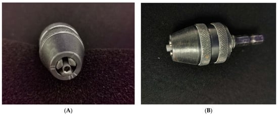 Figure 1. Transfer accessory—modified mandrel and implant analog: (A) frontal view; (B) lateral view.
 - Choose the implant analog according to the implant system used clinically. Mount the implant analog in the chuck; a 2–3 mm scannable area should be available for an intraoral scanner (Figure 1).
- During a clinical appointment, obtain a digital impression of mandibular and maxillary arches in the correct occlusion. Create an Exocad (Exocad GmbH, Darmstadt, Germany) order and import the 3D files.
- Choose an analog impression transfer that is suitable for the situation and exposes a sufficiently high area (4–5 mm) above the gingival margin. Scan intraorally the analog impression transfer screwed into the implant; export as an STL file. It is useful if the transfer abutment is sandblasted beforehand to achieve a better scan (Figure 2).
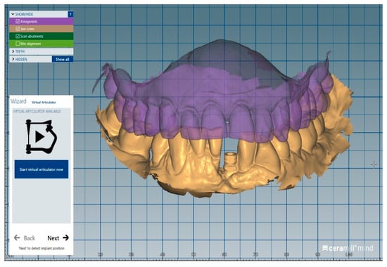 Figure 2. STL file of the analog transfer screwed in the implant.
 - Remove the analog transfer from the mouth and mount it in the transfer accessory.
- Scan with an intraoral scanner the analog transfer together with a sufficiently large area of the chuck, which will allow subsequent indexing in the CAD software; export as an STL file (Figure 3).
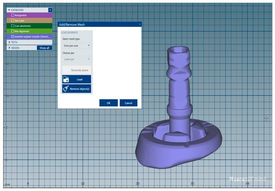 Figure 3. STL file of the analog transfer together with an area from the chuck.
 - Mount the digital scan body in the transfer accessory.
- Scan with an intraoral scanner the scan body together with a sufficient area of the chuck in order to permit correct indexing in the CAD software; export as an STL file (Figure 4).
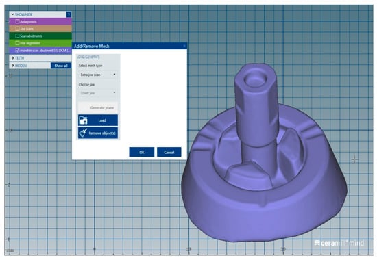 Figure 4. STL file of the scan body together with an area from the chuck.
 - Import into the Exocad order the STL files from point 5 as an “extrajaw scan,” which is used for indexing the visible part of the transfer abutment (Figure 5).
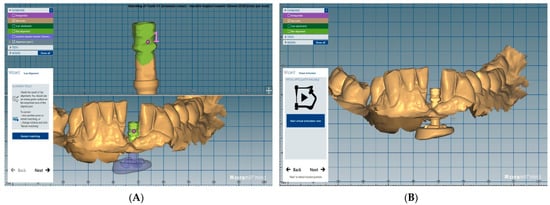 Figure 5. Analog transfer indexing: (A) index point; (B) superimposed STL files.
 - Import in the Exocad order the STL file from point 7 as an “extrajaw scan,” which is used for indexing the visible part of the device (chuck) (Figure 6).
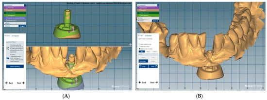 Figure 6. Scan abutment transfer indexing: (A) index point; (B) superimposed STL files.
 - Access the Expert mode and isolate in the jaw scan only the part that contains the digital scan body.
- Load a proper Ti base from the Exocad library (Figure 7) and perform restoration using the usual digital steps (Figure 8).
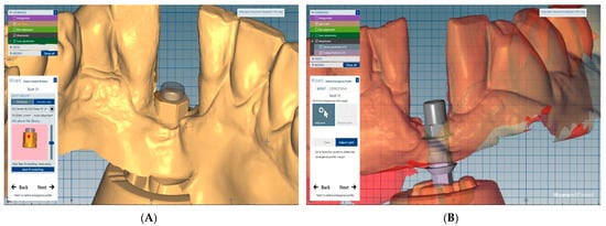 Figure 7. Ti base: (A) Ti base loading; (B) Ti base superimposed.
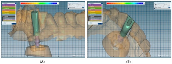 Figure 8. Final designs of the crown: (A) frontal view; (B) lingual view.
3. Discussion
Obtaining implant prostheses using digital technology has become a common procedure []. Digital implant impressions offer a viable and valid alternative to conventional impressions for single- and multi-unit implant-supported restorations. Digital impression accuracy is at the same level as conventional impression methods in the fabrication of crowns and short fixed dental prostheses []. However, in the case of complete arch scanning for extensive prosthetic rehabilitation, the accuracy of the digital method compared with the conventional one is controversial []. Current evidence on the superiority of one technique over the other is inconclusive []. Further in vitro and in vivo studies are needed to carefully evaluate the progress of complete arch scanning in dentistry.
Abdel-Azim et al. [] reported a similar marginal accuracy of conventional and digital impression methods for crown fabrication using Lava C.O.S. and iTero CAD/CAM systems and polyvinyl siloxane impressions. In their in vitro study, all measured marginal gaps were clinically acceptable. For single implants, the mean marginal gap was 61.4 μm for digital impressions, which is clinically acceptable []. A marginal gap level of 100 μm was defined as clinically acceptable [], and 120 μm was considered the maximum tolerable marginal opening []. Similar results have been reported in other studies [,].
In the process of manufacturing implant prostheses, the first step is to acquire the data using an intraoral scanner. The position and orientation of the implants are recorded by a digital impression of a scan body connected to the implant. This avoids the classic impression technique that is not preferred by patients and is also time-consuming []. However, low scanning quality can lead to inaccuracies in the implant’s position on the virtual model [,]. Some studies reported that digital implant impression accuracy was influenced by implant placement depth, the characteristics of the scan body, the type of scanner, implant angulation, the distance between the implants, and operator experience [,].
There are cases in which the implants are placed deep in subcrestal positions, and sometimes the scan bodies do not reach an optimal supragingival level so that they can be scanned accurately. This fact was also demonstrated in Nam’s recent study [] on the accuracy of implant position reproduction according to the exposed length of the body scan during optical scanning. He observed that the error increased rapidly for an implant placement depth of 4.5 mm, and was largest for a submersion of 6.0 mm. For this reason, we proposed the described technique.
Our solution is a four-step technique (Scheme 1):
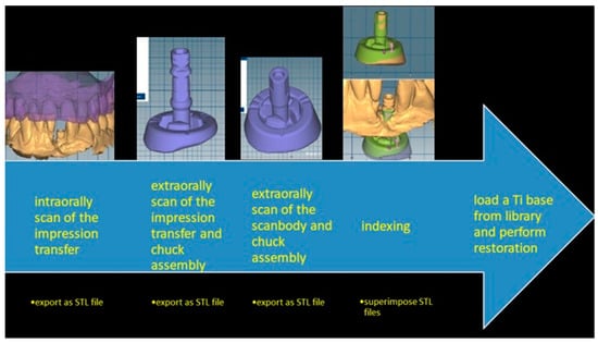
Scheme 1.
The advantage of the proposed method is a clear digital registration of the implant transfer abutment surface under any clinical conditions such as subgingival margin, narrow spaces, or lack of visibility. Accurate registration of the standard abutment subgingival margin can be obtained using a similar approach: intraoral digital impression of the exposed parts of the implant abutment (after cervical and occlusal refinements of the standard abutment are made), extraoral digital impression of the entire standard abutment mounted in the transfer device, and superimposition of the two files in the design software CAD application. In addition, this method allows to choose in the design workflow another virtual abutment that differs from the one tested intraorally.
- -
- An intraoral digital impression of an analog classic transfer, which exposes a sufficiently high area above the gingival margin.
- -
- An extraoral digital impression of an analog transfer mounted in the transfer accessory (Wolfcraft Keyless Chuck Metal 2625000), which allows to achieve an accurate and reproducible position. This device was chosen because it has proper dimensions, is related to the analog implant dimension, has a black and opaque color, can be easily grasped by the hand during the grinding procedures, allows easy mounting of the prosthetic components, and can be sterilized due to its entirely metallic surface. We made three different marks on the chuck’s head with a metal bur for better horizontal indexing of the chuck’s head and the impression transfer assembly with the chuck’s head and scan body assembly. The connection between the chuck and the implant analog must remain fixed so the vertical housing of the transfer and the scan body will be the same.
- -
- An extraoral digital impression of the scan body mounted in the same analog in the transfer accessory.
- -
- Indexing, which involves replacement in the CAD application of the transfer abutment from the intraoral scanning with the same one scanned in the accessory device. This is so the virtual image of the accessory transfer device will be incorporated in the intraoral scan and replacement in the CAD application of the transfer abutment used intraorally with the original scan abutment, using as a reference the virtual image of the accessory transfer device.
The same device could also be used to build a library with various standard abutments that can replace the abutment that has been tried intraorally.
There are limitations to the method. The spatial accuracy of the repositioning was achieved using the CAD software algorithm. A future study is needed for the validation and physical confirmation of this method. In addition, future studies should elucidate the minimum scannable area of the scan body so that the digital impression method work predictably.
4. Summary
In this paper, we proposed an easy and quick implant digital impression method, which has minimum time and cost investment and can solve many difficult situations that occur in everyday practice.
Author Contributions
Conceptualization, A.E.P. and S.D.; methodology, L.O.; software, A.E.P.; validation, A.E.P., S.D. and L.O.; formal analysis, S.D.; investigation, L.O.; resources, A.E.P.; data curation, S.D.; writing—original draft preparation, L.O.; writing—review and editing, S.D.; visualization, S.D.; supervision, A.E.P.; project administration, A.E.P.; funding acquisition, S.D. All authors have read and agreed to the published version of the manuscript.
Funding
This research received no external funding.
Institutional Review Board Statement
Not applicable.
Informed Consent Statement
Written informed consent has been obtained from the patient(s) to publish this paper.
Conflicts of Interest
The authors declare no conflict of interest.
References
- Matta, R.E.; Adler, W.; Wichmann, M.; Heckmann, S.M. Accuracy of impression scanning compared with stone casts of implant impressions. J. Prosthet. Dent. 2017, 117, 507–512. [Google Scholar] [CrossRef] [PubMed]
- Lee, S.J.; Betensky, R.A.; Gianneschi, G.E.; Gallucci, G.O. Accuracy of digital versus conventional implant impressions. Clin. Oral Implant. Res. 2015, 26, 715–719. [Google Scholar] [CrossRef] [PubMed]
- Nedelcu, R.; Olsson, P.; Nystrom, I.; Rydénc, J.; Thora, A. Accuracy and precision of 3 intraoral scanners and accuracy of conventional impressions: A novel in vivo analysis method. J. Dent. 2018, 69, 110–118. [Google Scholar] [CrossRef] [PubMed]
- Ahlholm, P.; Sipila, K.; Vallittu, P.; Jakonen, M.; Kotiranta, U. Digital versus conventional impressions in fixed prosthodontics: A review. J. Prosthodont. 2018, 27, 35–41. [Google Scholar] [CrossRef] [PubMed] [Green Version]
- Rutkūnas, V.; Gečiauskaitė, A.; Jegelevičius, D.; Vaitiekūnas, M. Accuracy of digital implant impressions with intraoral scanners. A systematic review. Eur. J. Oral Implantol. 2017, 10 (Suppl. 1), 101–120. [Google Scholar] [PubMed]
- Logozzo, S.; Kilpelä, A.; Mäkynen, A.; Zanetti, E.M.; Franceschini, G. Recent advances in dental optics—Part II: Experimental tests for a new intraoral scanner. Opt. Lasers Eng. 2014, 54, 187–196. [Google Scholar] [CrossRef]
- Kurosaki, Y.; Mino, T.; Maekawa, K.; Izumi, K.; Kuboki, T. Digital transfer of the subgingival contour and emergence profile of the provisional restoration to the final bone-anchored fixed restoration. J. Prosthodont. Res. 2019, 63, 125–129. [Google Scholar] [CrossRef] [PubMed]
- Sasada, Y.; Huynh-Ba, G.; Funakoshi, E. Transferring subgingival contours around implants and the intaglio surface of the pontic to definitive digital casts by using an intraoral scanner: A technique. J. Prosthet. Dent. 2020, 123, 210–214. [Google Scholar] [CrossRef]
- Hinds, K.F. Custom impression coping for an exact registration of the healed tissue in the esthetic implant restoration. Int. J. Periodontics Restor. Dent. 1997, 17, 584–591. [Google Scholar]
- Grizas, E.; Kourtis, S.; Andrikopoulou, E.; Romanos, G.E. A detailed decision tree to create, preserve, transfer, and support the emergence profile in anterior maxillary implants using custom abutments. Quintessence Int. 2018, 49, 349–364. [Google Scholar]
- Fluegge, T.; Att, W.; Metzger, M.; Nelson, K. A novel method to evaluate precision of optical implant impressions with commercial scan bodies-an experimental approach. J. Prosthodont. 2017, 26, 34–41. [Google Scholar] [CrossRef] [PubMed]
- Motel, C.; Kirchner, E.; Adler, W.; Wichmann, M.; Matta, R.E. Impact of Different Scan Bodies and Scan Strategies on the Accuracy of Digital Implant Impressions Assessed with an Intraoral Scanner: An In Vitro Study. J. Prosthodont. 2020, 29, 309–314. [Google Scholar] [CrossRef] [PubMed] [Green Version]
- Nam, N.-E.; Shin, S.-H.; Lim, J.-H.; Lee, B.; Shim, J.-S.; Kim, J.-E. Accuracy of Implant Position Reproduction According to Exposed Length of the Scan Body during Optical Scanning: An In Vitro Study. Appl. Sci. 2021, 11, 1689. [Google Scholar] [CrossRef]
- Mai, H.Y.; Seo, J.-M.; Jung, J.-K.; Lee, D.-H. Strategic Use of CAD-CAM Interim Restoration for the Recovery of the Vertical Dimension of Occlusion in the Posterior Partially Edentulous Jaw. Appl. Sci. 2020, 10, 7735. [Google Scholar] [CrossRef]
- Celeghin, G.; Franceschetti, G.; Mobilio, N.; Fasiol, A.; Catapano, S.; Corsalini, M.; Grande, F. Complete-Arch Accuracy of Four Intraoral Scanners: An In Vitro Study. Healthcare 2021, 9, 246. [Google Scholar] [CrossRef] [PubMed]
- Michelinakis, G.; Apostolakis, D.; Kamposiora, P.; Papavasiliou, G.; Özcan, M. The direct digital workflow in fixed implant prosthodontics: A narrative review. BMC Oral Health 2021, 21, 1–24. [Google Scholar] [CrossRef]
- Abdel-Azim, T.; Rogers, K.; Elathamna, E.; Zandinejad, A.; Metz, M.; Morton, D. Comparison of the marginal fit of lithium disilicate crowns fabricated with CAD/CAM technology by using conventional impressions and two intraoral digital scanners. J. Prosthet. Dent. 2015, 114, 554–559. [Google Scholar] [CrossRef]
- May, K.B.; Russel, M.M.; Razzoog, M.E.; Lang, B.R. Precision of fit: The Procera AllCeram crown. J. Prosthet. Dent. 1998, 80, 394–404. [Google Scholar] [CrossRef]
- McLean, J.W.; von Fraunhofer, J.A. The estimation of cement film thickness by an in vivo technique. Br. Dent. J. 1971, 131, 107–111. [Google Scholar] [CrossRef]
- Vennerstrom, M.; Fakhary, M.; Von Steyern, P.V. The fit of crowns produced using digital impression sys-tems. Swed. Dent. J. 2014, 38, 101–110. [Google Scholar]
- Choi, Y.D.; Lee, K.E.; Mai, H.N.; Lee, D.H. Effects of scan body exposure and operator on the accuracy of image matching of implant impressions with scan bodies. J. Prosthet. Dent. 2020, 124, e1–379.e6. [Google Scholar] [CrossRef] [PubMed]
- Andriessen, F.S.; Rijkens, D.R.; van der Meer, W.J.; Wismeijer, D.W. Applicability and accuracy of an intraoral scanner for scanning multiple implants in edentulous mandibles: A pilot study. J. Prosthet. Dent. 2014, 111, 186–194. [Google Scholar] [CrossRef] [PubMed]
Publisher’s Note: MDPI stays neutral with regard to jurisdictional claims in published maps and institutional affiliations. |
© 2022 by the authors. Licensee MDPI, Basel, Switzerland. This article is an open access article distributed under the terms and conditions of the Creative Commons Attribution (CC BY) license (https://creativecommons.org/licenses/by/4.0/).