Article

Implementing Data-Driven Approach for Modelling Ultrasonic Wave Propagation Using Spatio-Temporal Deep Learning (SDL)

by
Thulsiram Gantala
* and
Krishnan Balasubramaniam
Centre for Non-Destructive Evaluation, Department of Mechanical Engineering, Indian Institute of Technology Madras, Chennai 600036, India
*
Author to whom correspondence should be addressed.
Appl. Sci. 2022, 12(12), 5881; https://doi.org/10.3390/app12125881
Submission received: 29 March 2022 / Revised: 16 May 2022 / Accepted: 19 May 2022 / Published: 9 June 2022
(This article belongs to the Special Issue Ultrasonic Modelling for Non-destructive Testing)

Abstract

:
In this paper, we proposed a data-driven spatio-temporal deep learning (SDL) model, to simulate forward and reflected ultrasonic wave propagation in the 2D geometrical domain, by implementing the convolutional long short-term memory (ConvLSTM) algorithm. The SDL model learns underlying wave physics from the spatio-temporal datasets. Two different SDL models are trained, with the following time-domain finite element (FE) simulation datasets, by applying: (1) multi-point excitation sources inside the domain and (2) single-point excitation sources on the edge of the different geometrical domains. The proposed SDL models simulate ultrasonic wave dynamics, for the forward ultrasonic wave propagation in the different geometrical domains and reflected wave propagation phenomenon, from the geometrical boundaries such as curved, T-shaped, triangular, and rectangular domains, with varying frequencies and cycles. The SDL is a reliable model, which generates simulations faster than the conventional finite element solvers.

1. Introduction

Ultrasonic wave propagation is used in various applications, including biomedical imaging [1], nondestructive evaluation [2,3], seismic and geological studies [4], etc. The numerical modeling of the ultrasonic waves is critical, for improving the understanding of the underlying physics of these applications. The ultrasonic wave propagation phenomenon is widely modeled using Finite Element [5,6,7,8], Finite Difference [9], and Finite Volume [10] techniques. Ultrasonic wave propagation is modeled by the widely used FE analysis, through solving the partial differential equations on discrete nodes, using iterative time-steeping schemes. Due to the transient nature of the wave propagation and the three-dimensional volume in which the ultrasonic wave is modeled, the computational resources and the time to complete the calculations are often extensive, thus limiting the utilization of modeling. We can develop a data-driven solver for modelling wave propagation, by capturing the underlying physics from numerical simulation datasets, as an alternative approach [11].
In recent years, modern deep-learning techniques, such as long short-term memory (LSTM) [12,13], have been successful in many domains [14,15]. These techniques are used in many applications, such as propagating the latent space to the future [16,17], using [18] the LSTM network to realize gesture recognition, wave propagation [19], automating tumor segmentation in whole breast [20], and shear wave elastography [21]. Since the ultrasonic wave propagation prediction is a sequence of spatio-temporal images data, so, typically, the LSTM approach will not provide and capture the desired results [22]. The convolutional long short-term memory (ConvLSTM) networks, effectively, address the long-range simulation prediction [23,24,25,26]. The ConvLSTM approach uses the convolutional operation inside the LSTM cell, to pair the temporal state with spatial information. On the other hand, the wave propagation simulation solver can be built using a convolutional neural network (CNN) architecture [27,28]. Another group in the research community is adapting physics-informed neural networks to solve the partial differential equations [29,30,31].
In the current work, the authors have developed two separate spatio-temporal deep learning (SDL) models. In the prior work, [26] shows the modeling forward wave propagation simulation in a 2D domain with different physical settings. The authors, further, want to generalize the SDL network for modelling forward wave propagation in the different geometrical domains (i.e., other than the trained domains) and reflecting wave propagation simulation in the different geometrical boundaries. In the first SDL model, the network algorithm is tuned to incorporate geometrical domain information and trained using datasets containing numerous ultrasonic wave simulations, with single-point excitation to five-point excitation sources inside the solid medium, without reflection from the edges. This trained SDL model can be deployed for modelling real-time forward ultrasonic wave propagation in the different geometrical shapes. Whereas in the second SDL model, the learnable hyperparameters are tuned to generate wave propagation, without changing network architecture. The datasets used for training the second model have three distinct geometrical domains, with a single-point excitation source applied on the edges. This trained SDL model can be used to study the reflected wave propagation phenomenon from different geometrical boundaries, such as curved, T-shaped, triangular, and rectangular domains, with varying frequencies and cycles. Thus, depending on the availability of the datasets’s structure, we should employ one of these models for generating wave propagation. These training datasets have spatial and temporal features; hence, algorithms based on the recurrent neural network (RNN) are treated as the most suitable for modelling ultrasonic wave propagation simulations [19].
This paper is organized as follows: Section 2 describes the procedure for generating training datasets, and Section 3 details the SDL model formulation for the wave propagation phenomenon. Section 4 discusses the SDL model implementation and results, to generalize for different domains. Section 5 brings the summary of the work, along with concluding remarks.

2. Training Datasets Generation through Finite Element Simulation

To generate wave propagation in solid media using AI algorithms requires large volumes of training datasets. The following section, comprehensively, discusses the methodology adopted for generating the FE training datasets.

2.1. Finite Element Modelling of Ultrasonic Wave Propagation in Solid Media

The datasets to train the AI model are created by modelling numerous time-domain 2D FE simulations, by solving the governing partial differential equation, by employing the commercial FE Abaqus/Explicit (v. 18.0) solver (see ABAQUS User Manual v. 6.11, Dassault system, Providence, RI, USA). The two-dimensional FE CAD models are created using carbon steel isotropic material properties, as shown in Figure 1a,b. The mechanical properties of carbon steel are a mass density of ρ = 7850 kg/m 3 , Young’s modulus of E = 200 GPa, and Poisson’s ratio of ν = 0.29. The 2D part is discretized with a four-noded quadrilateral mesh size of 3.2 × 10 5 mm, which is about 22 elements per wavelength λ s h e a r , for 5 MHz in carbon steel for mesh convergence. A similar approach is followed from our prior work for modelling [3]. The two cycles of the Hanning-windowed tone burst signal of 5 MHz frequency are used to trigger an incident wave. To avoid the undesired reflection from the boundaries’s [32] absorbing, boundary conditions are applied using the ALID (absorbing layers using increasing damping) method, as shown in Figure 1a. After completing the simulation, the spatial and temporal scale is adjusted during the post-processing, to ensure that the necessary temporal and spatial information is captured in the displacement plots.

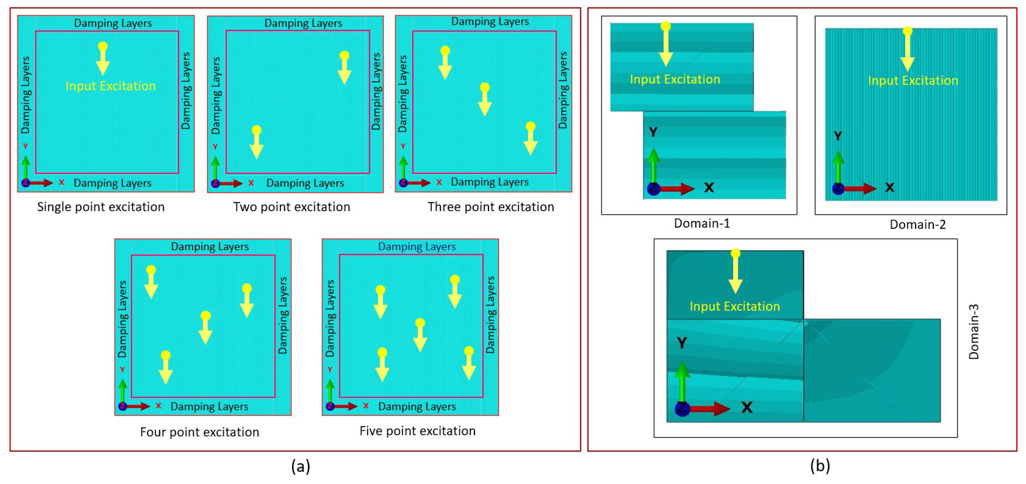
2.2. Type-1 Datasets Creation: Forward Wave Propagation Simulation

The type-1 training datasets is created by modelling several 2D FE simulations, by changing the following parameters: (a) the incident wave is triggered in the X-direction or in the Y-direction inside the domain in each simulation, (b) the excitation point sources are distributed randomly throughout the domain using a uniform probability distribution, and (c) the excitation sources vary from single to five-point excitation sources, as shown in Figure 1a. A total of 1250 simulations are generated for the training, consisting of 250 CAD models, with 35 × 35 mm physical dimensions for each (a) single-point excitation, (b) two-point excitation, (c) three-point excitation, (d) four-point excitation, and (e) five-point excitation source, respectively. These displacement plots are saved as frames, with the time interval of 0.0074 μ s, for the total simulation.

2.3. Type-2 Datasets Creation: Reflection Wave Propagation Simulation

For the type-2 training datasets generation, we have created three different geometrical 2D CAD models, as shown in Figure 1b. The overall physical dimension of each model is 40 mm in length and 40 mm in height. A total of 1500 CAD models are created, of which 500 are of the same geometrical shape. The excitation load is applied on the top-edge nodes of the CAD models, as shown in Figure 1b, and on the remaining edges, a traction-free boundary condition is applied to allow the sidewall and back wall reflections. After performing each FE simulation, the displacement plots are saved as a sequence of images, with a time interval of 0.0125 μ s.
One FE simulation generation executed using Dual Intel Xeon Platinum 8168 processor with 48 cores machine (Figure 1b) took 3600 s, using time-domain FE analysis, which is a time-consuming process. We have introduced the SDL model to overcome this limitation, which generates wave propagation simulations in minimal time once trained.

3. The Formulation of Spatio-Temporal Deep Learning Model for Ultrasonic Wave Propagation

The LSTM is a unique RNN structure modeled for addressing vanishing gradients and learning long-range dependencies in the deep machine learning framework. The LSTM shown in Figure 2 consists of the following elements: a memory cell C t , which can accumulate, and the forgetthe state being tackled, time step to time step. i t , f t , and o t are the input, forget, and output gate, respectively. The i t monitors the flow of new input into the C t , the responsibility of f t is to remove irrelevant information from C t , and the work of o t is to send information from C t to hidden state H t . The H t could retain the memory of past information from the sequence data. Since the nature of the training datasets is in the form of spatio-temporal sequence images, the LSTM approach suffers from capturing the spatial features from the 2D images. The ConvLSTM network, effectively, learns the spatial and temporal features from the sequential images because it uses the convolutional operation inside the LSTM cell to pair the temporal state with spatial information. The formulation of the ConvLSTM model is followed from [23].
i t = σ ( W x i X t + W h i H t 1 + W c i C t 1 + b i )
f t = σ ( W x f X t + W h f H t 1 + W c f C t 1 + b f )
C t = f t C t 1 + i t T a n h ( W x c X t + W h c H t 1 + b c )
o t = σ ( W x o X t + W h o H t 1 + W c o C t + b o )
H t = o t T a n h ( C t )
here, ‘W’ denotes the weights, and ‘b’ represents the network’s biases. The convolutional operation is marked with ‘∗’ and ‘∘’, representing the Hadamard product.
We have used the proposed SDL network for our spatial-temporal sequence generation problem, as shown in Figure 2, for two types of different training datasets. First, for type-1 datasets, we have modified the existing ConvLSTM algorithm to fuse the geometrical information with each hidden dimension output, which is similar to our previous study [26]. So, for the type-2 datasets, we have modified the suitable network parameters, such as hidden dimensions and kernel size, instead of modifying the network architecture.
These models consist of an encoder and a decoder network, containing a series of convolutional LSTM cells stacked together, since a single ConvLSTM layer will not capture the forward and reflected wave dynamics from training datasets, due to the spatial-temporal nature. Each input data sequence is fed into each encoder ConvLSTM cell, to learn the wave propagation physics from the datasets. The ConvLSTM layer takes the batch of the 3D input tensor (length × width × time step) and outputs the hidden state ( H t ). Then, the following input tensor, similarly with H t , is given input to the next layer of the ConvLSTM cell. Due to the convolutional operation, the model captures the required features from the datasets, during the processing into layers of ConvLSTM cells. The encoder, iteratively, processes input sequences through various ConvLSTM cells and outputs the embedding tensor, representing wave propagation. The output of the encoder-embedded tensor is fed to the decoder network, to produce predicted wave propagation simulations. The outcome of the decoder cell’s sequence is passed to the 3D CNN layers, with a sigmoid activation function, to transform into an actual wave propagation prediction.

4. Results and Discussion

The implementation of the SDL model, using type-1 and type-2 training datasets, as well as testing results, are described in detail in this section.

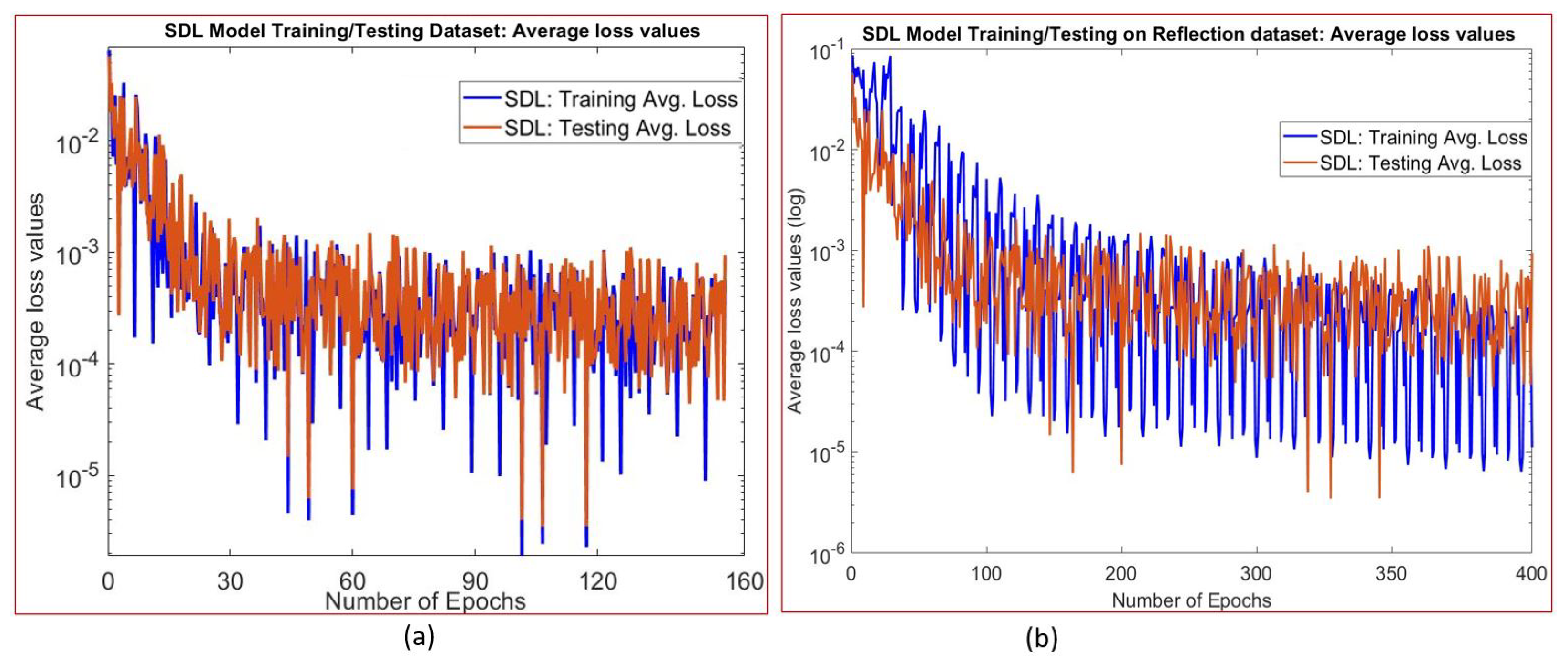
4.1. SDL Model Implementation on Type-1 Datasets: Forward Wave Propagation Simulation

The proposed SDL network is implemented in PyTorch Lightning, an open-source Python library (see https://www.pytorchlightning.ai (accessed on 28 March 2022)), by integrating multi-GPU, and trained using simulation-assisted FE datasets of type-1 (Section 2.2). These training datasets from the FE analysis form a sequence of images in each simulation. Each simulation contains 675 images, and a mini-batch of 15 images is randomly selected. A sequence of 5 images is used for input to the network from the mini-batch, and the next successive 10 images are used to compare the network-predicted output. These images are in grayscale, with a size of 128 × 128 pixels. The SDL architecture contains the four layers of an encoder structure, and the four layers of the decoder structure are stacked together. Each layer contains 256 hidden states, and the convolutional operation is performed on each input image, with a kernel size of 5 × 5 with the same padding. The geometrical information from the CAD model is captured in the binary matrix, by assigning ‘1’ for the inside and ‘0’ for an outside domain, as shown in Figure 2. The binary matrix and the sequence of frames are used as input to the network. This binary matrix is multiplied with an output of a hidden state, before updating the next hidden state. In total, 80% of the simulations are used for training and the remaining for testing the model.
To predict the more accurate simulations from the SDL model, the suitable learnable parameters and hyperparameters are selected. The hyperparameters are selected before the training process and cannot be altered, and the weights and basis are learnable parameters that must be updated during training. First, the input datasets are fed and propagated to compute the output through the network. This predicted output is compared with the ground truth, to determine the error and, then, calculate the derivative of the error function, with respect to the network learnable parameters. Now, network weights and basis are updated to minimize the error; this process is well known as the back-propagation algorithm. The back-propagation algorithm is suitable for fixed-size input-output pairs in feed-forward neural networks [33]. However, in the current work, the training datasets are spatiotemporal, so the back-propagation through time (BPTT) algorithm is employed, instead of the back-propagation algorithm. The mean square error (MSE) loss function is minimized during the training process, using the back-propagation through time (BPTT) algorithm. The MSE loss function used in this network is as follows:
M S E = 1 n t = 1 n ( y ^ i y i ) 2
here, y ^ is the predicted output sequence, y is the ground truth sequence, and n = the number of instances. While training, the ConvLSTM network, as shown in Figure 2, predicts the output for one input in each time step. So, the BPTT works by unrolling all input time steps. Furthermore, each time step has one input time step, one output time step, and a copy of the network. Then, the error is calculated for every time step and accumulated for each time step. The network is unrolled back, and learnable parameters are updated. The network learning rate is set to a constant value of 1.0 × 10 4 in the Adam optimizer and trained for 150 epochs. The network took a total of 36 h to train, using two NVIDIA GeForce RTX 3090 GPU processors. The average loss value computed by comparing network-predicted output with ground truth is used to determine the model learning efficiency. Figure 3a shows the average loss values over the number of epochs, and training loss is determined to be 6.0 × 10 4 , whereas testing loss is 2.0 × 10 4 . The performance of the train SDL model is validated, by feeding the remaining 20% of testing datasets of single to multi-point excitation sources simulations, and the effectiveness of the proposed model on testing datasets can be referred from our prior work [26].

4.1.1. Evaluation Metric

To assess the efficiency of the SDL model prediction on wave propagation simulation, we have employed the Mean Absolute Error (MAE), Root Mean Square Error (RMSE), and Mean Absolute Percentage Error (MAPE), to compute using the equations below:
M A E = 1 n i = 1 n | Y i Y ¯ i |
R M S E = ( 1 n ) i = 1 n ( Y i Y ¯ i ) 2
M A P E = 100 % n i = 1 n Y i Y ¯ i Y i
here, Y i is the ground truth from FE wave propagation simulation, Y i ¯ is the predicted from SDL model generated wave propagation simulation, and n = number of instances.

4.1.2. Ultrasonic Wave Propagation on Different Geometrical Domain Modelling

This section presents the comparative study between the SDL model and FE, to simulate the forward wave propagation simulations for the different geometrical domains, shown in Figure 4. So, we have considered two scenarios of different geometrical domains (i.e., other than the trained domains) with point source excitation to evaluate the trained SDL model, which is not used during training or testing. The SDL model is, initially, trained with a single-step short-term prediction during the training process. Then, the model takes a 5-input image sequence from the training set and predicts the next following consecutive 10-output image sequence. These model-predicted images are fed back to the model’s input, iteratively, to predict the complete long-term simulation. Then, the SDL model generated simulation is compared with the actual FE ultrasonic wave propagation simulation.
Figure 4 shows the FE and SDL model simulations over the total simulation time for geometry-1 and geometry-2. In particular, the top row in Figure 4a shows the FE datasets, and the bottom row shows the SDL model output datasets at identical time intervals at t = (0.9 μ s, 1.5 μ s, 2.2 μ s, 2.2 μ s, 3.6 μ s), for the long-term simulation of geometry-1. Similarly, Figure 4b depicts the wave propagation of geometry-2. The proposed SDL model could capture the constructive and destructive interference at the wavefront interaction and match the FE simulation. We can conclude that the SDL model-generated simulations are in good agreement with FE.
For quantitative assessment, we have extracted the displacement values at x = 17.5 mm and y = 0 to 35 mm, in all the frames from Figure 4 (as shown by the vertically dotted yellow line). Figure 5a,b show the wavefront line scans for both geometry-1 and geometry-2. The line scans from the SDL model follow the same trend as the FE simulation line scans for all the frames, but some differences exist in amplitude and TOF. To find out the difference in amplitude and time of flight between the SDL and FE simulations, from the line scans in Figure 5 for each modelling scenario, we have used three methods (refer to Section 4.2) (1) the Mean Absolute Error (MAE), (2) Root Mean Square Error (RMSE), and (3) Mean Absolute Percentage Error (MAPE), to estimate the error in each frame. Table 1 shows the summary of the MAE, RMSE, and MAPE on amplitude and TOF error. The maximum MAE is in order of 10 2 , the maximum RMSE is in order of 10 1 , and MAPE is 115.9% on amplitude error, over all the time frames. The maximum MAE is in order of 10 1 , the maximum RMSE is 3.15, and MAPE is 3.34% on TOF error, over all the time frames. The evaluation finding shows that the proposed SDL model could, efficiently, simulate ultrasound wave propagation on the different geometrical domains, other than the trained domain, with good accuracy.

4.2. SDL Model Implementation on Datasets Type-2: Reflection Wave Propagation Simulation

A similar approach is followed from Section 4.1 to train the SDL model using the type-2 datasets of reflection wave propagation simulation (from Section 2.3). The SDL architecture consists of six layers of an encoder structure and six layers of a decoder structure; these structures are stacked together. Each encoder or decoder structure contains 256 hidden dimensions, and during convolutional operation, a 5 × 5 kernel size and the same padding are used. The average loss value over the number of epochs is shown in Figure 3b. The average training loss is determined to be 1.0 × 10 5 , the testing loss is 4.0 × 10 5 , and the loss value becomes stabilized with an increase in the number of epochs.

4.2.1. Generalization to Different Geometrical Boundary Modelling: Reflected Wave Propagation from Boundaries

To generalize the SDL model, we have modeled the ultrasonic wave propagation in four different geometrical domains: curved, T-shaped, and triangular. The SDL model predicted simulation is compared with the FE. Figure 6a–c shows the reflected ultrasonic wave propagation simulation for curved, T-shaped, and triangular domains, respectively. In each figure, the top row simulations are from the FE, and the bottom row shows the predicted simulation from the SDL model. During the training process, the proposed SDL model is trained with straight edge boundaries, but it could generate the simulation for curved boundaries (Figure 6a) and diagonal boundaries (Figure 6c). The SDL model has learned the wave interactions at the domain sharp edge and could generate the reflection wave propagation from the sharp edges (Figure 6b). So, the SDL model accurately predicts reflection wave propagation from the side and back walls as well as matches with the FE.
Quantitatively exploring the SDL model prediction on reflected wave propagation, we have extracted the displacement values along the line at x = 20 mm and y = 0 to 40 mm, from all the geometrical domain frames. Figure 7 shows the wavefront line scans between the SDL and FE model, for all the geometrical boundaries datasets. The SDL model-based line scans follow a similar trend to FE simulation-based line scans. To find out the amplitude and TOF difference between the two methods, we have employed MAE, RMSE, and MAPE, to calculate the error on each frame. A similar approach is adopted from Section 4.2. The comparison summary is shown in Table 2 for each frame for each domain. The maximum MAE is in order of 10 2 , the maximum RMSE is in order of 10 1 , and MAPE is 78.7% on amplitude error, over all the time frames. The maximum MAE is 1.86, the maximum RMSE is 2.56, and MAPE is 5.37% on an error in TOF, between all the geometrical domains. The SDL model could simulate curved domains (Figure 6a), sharp corner reflection (Figure 6b), and diagonal boundaries (Figure 6c), even though we have not used these geometries based datasets while the training process. The SDL model-generated simulations are reasonably in good agreement with FE simulation.
Once trained, the SDL model takes approximately 180 s to generate the 1040 frames in one simulation sequence, for 13 μ s total simulation time, with the time interval of 0.0125 μ s. The conventional FE solver takes 3600 s, using the same computer processor. Hence, we can infer that the proposed SDL model could simulate reflected wave propagation simulation for different geometrical boundaries with reduced computational requirements than FE simulation.

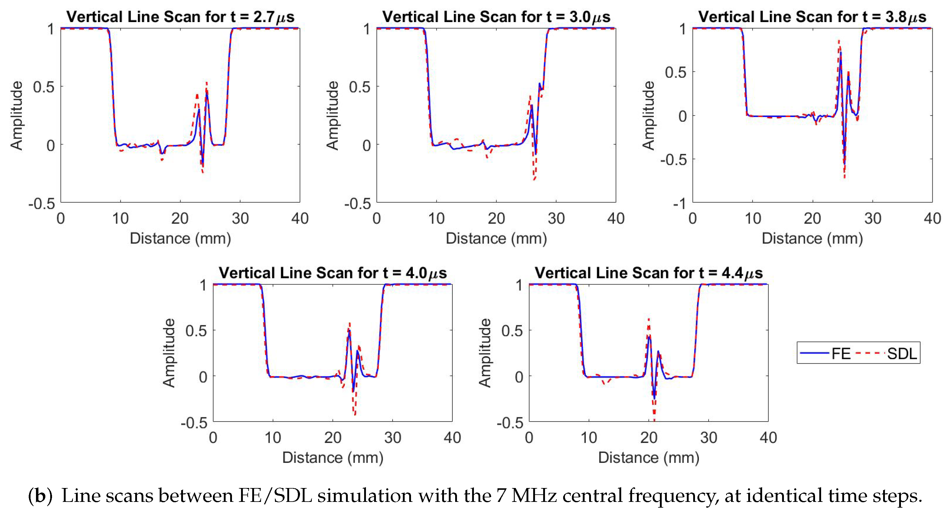
4.2.2. SDL Model Simulation for Reflected Wave Propagation with Varying Frequencies and Cycles

To determine the effectiveness of the proposed SDL model, we have modeled the different scenarios of varying excitation frequencies and the varying number of cycles on rectangular domains with a single-point excitation source on the top edge, to simulate reflected wave propagation. These datasets are not used during the training or testing of the network. We have modeled two sets of FE simulations on the rectangular domain, first, by varying the excitation frequencies of 4 MHz, 5 MHz, and 7 MHz with two cycles of the incident wave, and, second, by modelling with three cycles using 5 MHz frequency. The FE simulations are performed using a similar approach to Section 2.3. Here, we compare the SDL modeled simulation with the FE simulation, for different scenarios. Figure 8 shows the comparison of reflected wave propagation simulation for different excitation frequencies with two-cycle signal width, and the corresponding displacement values extracted along the yellow dashed line from Figure 8 for all the frames are shown in Figure 9a,b. Similarly, Figure 10 shows the comparison of the reflection wave propagation simulation modeled using a varying number of cycles with a 5 MHz central frequency. The corresponding displacement values extracted along the yellow dashed line from Figure 10 for all the time frames are shown in Figure 11a,b. We can observe that the proposed SDL model could generate reflection wave propagation for varying frequencies and cycles. The SDL simulations are in good agreement with FE simulations. The SDL-model-based line scans follow a similar trend as the FE simulation; however, amplitude and TOF differences are present in the line scans as the future time step prediction increases. We have utilized the same metrics that we used to evaluate different geometrical boundaries predictions, and the results are illustrated in Table 3. In this case, we are comparing the MAE, RMSE, and MAPE values for two different scenarios as follows: (1) the simulation between the frequencies of 4 MHz, 5 MHz, and 7 MHz with two cycles and (2) simulation, with the number of cycles being two and three, with 5 MHz frequency. We can notice the following conclusion from Table 3: (1) with an increase in the excitation frequencies other than the training frequency, the MAE, RMSE, and MAPE values increase, but the overall magnitude is in the order of 10 2 for MAE and 10 1 for RMSE, while the maximum MAPE is 221% on amplitude. (2) Increasing the number of cycles, the MAE, RMSE, and MAPE values are increased, but, overall, are in order of 10 2 , for MAE and 10 1 for RMSE, while the maximum MAPE is 447 % on amplitude. (3) When increasing the number of cycles, the MAE, RMSE, and MAPE values are increased in amplitude and TOF.
The trend in MAE, RMSE, and MAPE values of amplitude as well as TOF is, closely, following the increasing function with respect to increasing in future time step prediction. The apparent trend from Table 3 is that the performance of the SDL model prediction on reflected wave propagation simulation deteriorates, as the number of future time steps to be predicted increases. Even if we can observe that from Figures 6, Figure 8, and Figure 10, we can infer that the results obtained from the SDL model are in reasonably good agreement with the FE simulation until the t = 4.0 μ s frame, for all the domains. Still, there is some compounding errors that started accumulating time instances afterward. The generation of accurate waveform amplitude from back-wall reflection depends on the various parameters in the network architecture, such as the number of hidden layers, kernel size, input–output frames, etc. However, the best suitable learnable hyperparameters and network parameters need to be selected, which may require additional computational resources and time to train the model. The SDL models developed in this work are applicable for solving the forward- and reflected-wave propagation in different 2D geometrical domains. The same approach can be extended for modelling the 3D domain simulation and the wave phenomenon of scattering effect with defects.

5. Conclusions

In this work, the data-driven spatio-temporal deep learning (SDL) model is used to rapidly compute ultrasonic wave propagation for modelling forward and reflected ultrasonic wave propagation in the different geometrical domains as well as varying frequencies and cycles. The SDL is trained with simulation-assisted FE simulation data. Here, we have used two types of training datasets to teach two individual SDL models, using multiple point sources of wave simulation in a single domain and reflected wave propagation from boundaries with different geometries. The SDL can learn representations of the time-domain ultrasonic wave propagation phenomenon from the training datasets, thus employing a data-driven approach to understand the underlying physics to build an AI predictive model to simulate ultrasonic wave propagation and reflection from boundaries. The SDL model can be used for modelling forward and reflected ultrasonic wave propagation simulations, in the different geometrical domains and varying incident wave parameters, such as frequencies and number of cycles with significantly reduced time (20×) and computation resources, which compare well with the FE model simulations. Furthermore, the SDL models have, traditionally, been successfully used for creating conventional 2D wave propagation simulations. Understanding the seismic wave propagation in the geological structure is complex, due to various geological and geometrical structures, to take into account that the various numerical methods are used to model seismic wave propagation in the geological structure but need huge numerical costs and memory storage for handling larger domains with higher frequencies. However, the proposed SDL model can be a direct replacement, where time and a high-processor computer are the constraints for seismic wave propagation simulation. Hence, the SDL model approach may be further extended for modelling the scattering effects of the defects and virtual source imaging in nondestructive evaluation and biomedical imaging.

Author Contributions

T.G. and K.B., together, conceptualized and developed the methodology. T.G. generated the training datasets from a numerical simulation. K.B. helped with the validation and interpretation of results. All authors have equally contributed to the theoretical and numerical foundation of the manuscript. All authors have read and agreed to the published version of the manuscript.

Funding

This research work was supported by SERB, DST, the government of India, and a CII partnernership with Baker Hughes, under the prime minister’s Fellowship Scheme for Doctoral Research, 2020.

Institutional Review Board Statement

Not applicable.

Informed Consent Statement

Not applicable.

Data Availability Statement

The datasets generated during and/or analysed during the current study are available from the corresponding author on reasonable request.

Conflicts of Interest

The authors declare no conflict of interest.

References

  1. Zhu, Y.C.; AlZoubi, A.; Jassim, S.; Jiang, Q.; Zhang, Y.; Wang, Y.B.; Ye, X.D.; Du, H. A generic deep learning framework to classify thyroid and breast lesions in ultrasound images. Ultrasonics 2021, 110, 106300. [Google Scholar] [CrossRef] [PubMed]
  2. Liu, Y.; Liu, E.; Chen, Y.; Wang, X.; Sun, C.; Tan, J. Study on Propagation Depth of Ultrasonic Longitudinal Critically Refracted (LCR) Wave. Sensors 2020, 20, 5724. [Google Scholar] [CrossRef] [PubMed]
  3. Gantala, T.; Balasubramaniam, K. Automated Defect Recognition for Welds Using Simulation Assisted TFM Imaging with Artificial Intelligence. J. Nondestruct. Eval. 2021, 40, 28. [Google Scholar] [CrossRef]
  4. Chen, S.; Wang, H.; Xu, F.; Jin, Y.Q. Target Classification Using the Deep Convolutional Networks for SAR Images. IEEE Trans. Geosci. Remote. Sens. 2016, 54, 4806–4817. [Google Scholar] [CrossRef]
  5. Raja, N.; Balasubramaniam, K. Experimental Study on Dispersion Effects of F (1,1) Wave Mode on Thin Waveguide When Embedded with Fluid. Sensors 2021, 21, 322. [Google Scholar] [CrossRef]
  6. Nakahata, K.; Sugahara, H.; Barth, M.; Köhler, B.; Schubert, F. Three dimensional image-based simulation of ultrasonic wave propagation in polycrystalline metal using phase-field modeling. Ultrasonics 2016, 67, 18–29. [Google Scholar] [CrossRef]
  7. Guha, A.; Aynardi, M.; Shokouhi, P.; Lissenden, C.J. Shear-Actuation and Vibrometer Reception of Penetrating Ultrasonic Guided Wave Modes in Human Tibia. Appl. Sci. 2020, 10, 8397. [Google Scholar] [CrossRef]
  8. Moon, S.; Kang, T.; Han, S.; Kim, K.M.; Jin, H.H.; Kim, S.W.; Kim, M.; Seo, H. FEA-Based Ultrasonic Focusing Method in Anisotropic Media for Phased Array Systems. Appl. Sci. 2021, 11, 8888. [Google Scholar] [CrossRef]
  9. Shivaprasad, S.; Pandala, A.; Krishnamurthy, C.V.; Balasubramaniam, K. Wave localized finite-difference-time-domain modelling of scattering of elastic waves within a polycrystalline material. J. Acoust. Soc. Am. 2018, 144, 3313–3326. [Google Scholar] [CrossRef]
  10. Dutykh, D.; Katsaounis, T.; Mitsotakis, D. Finite volume schemes for dispersive wave propagation and runup. J. Comput. Phys. 2010, 230, 3035–3061. [Google Scholar] [CrossRef] [Green Version]
  11. Manidipa, D.; Ghosh, S.K. Data-Driven Approaches for Spatio-Temporal Analysis: A Survey of the State-of-the-Arts. J. Comput. Sci. Technol. 2020, 35, 665–696. [Google Scholar] [CrossRef]
  12. Hochreiter, S.; Schmidhuber, J. Long Short-Term Memory. Neural Comput. 1997, 9, 1735–1780. [Google Scholar] [CrossRef] [PubMed]
  13. Schmidhuber, J. Deep learning in neural networks: An overview. Neural Netw. 2015, 61, 85–117. [Google Scholar] [CrossRef] [PubMed] [Green Version]
  14. Connor, J.; Martin, R.; Atlas, L. Recurrent neural networks and robust time series prediction. IEEE Trans. Neural Netw. 1994, 5, 240–254. [Google Scholar] [CrossRef] [Green Version]
  15. Rautela, M.; Senthilnath, J.; Moll, J.; Gopalakrishnan, S. Combined two-level damage identification strategy using ultrasonic guided waves and physical knowledge assisted machine learning. Ultrasonics 2021, 115, 106451. [Google Scholar] [CrossRef]
  16. Srivastava, N.; Mansimov, E.; Salakhudinov, R. Unsupervised Learning of Video Representations using LSTMs. In Proceedings of the 32nd International Conference on Machine Learning, Lille, France, 6–11 July 2015; Bach, F., Blei, D., Eds.; PMLR: Lille, France, 2015; Volume 37, pp. 843–852. [Google Scholar]
  17. Liu, F.; Shen, T.; Luo, Z.; Zhao, D.; Guo, S. Underwater target recognition using convolutional recurrent neural networks with 3-D Mel-spectrogram and data augmentation. Appl. Acoust. 2021, 178, 107989. [Google Scholar] [CrossRef]
  18. Liu, G.Y.; Kong, D.Y.; Hu, S.G.; Yu, Q.; Liu, Z.; Chen, T.P.; Yin, Y.; Hosaka, S.; Liu, Y. Smart electronic skin having gesture recognition function by LSTM neural network. Appl. Phys. Lett. 2018, 113, 084102. [Google Scholar] [CrossRef]
  19. Sorteberg, W.E.; Garasto, S.; Cantwell, C.C.; Bharath, A.A. Approximating the solution of surface wave propagation using deep neural networks. In Proceedings of the INNS Big Data And Deep Learning Conference, Sestri Levante, Italy, 18–19 April 2019; Springer: Berlin/Heidelberg, Germany, 2019; pp. 246–256. [Google Scholar]
  20. Pan, P.; Chen, H.; Li, Y.; Cai, N.; Cheng, L.; Wang, S. Tumor segmentation in automated whole breast ultrasound using bidirectional LSTM neural network and attention mechanism. Ultrasonics 2021, 110, 106271. [Google Scholar] [CrossRef]
  21. Ahmed, S.; Kamal, U.; Hasan, M.K. DSWE-Net: A deep learning approach for shear wave elastography and lesion segmentation using single push acoustic radiation force. Ultrasonics 2021, 110, 106283. [Google Scholar] [CrossRef]
  22. Hughes, T.W.; Williamson, I.A.D.; Minkov, M.; Fan, S. Wave physics as an analog recurrent neural network. Sci. Adv. 2019, 5, Eaay6946. [Google Scholar] [CrossRef] [Green Version]
  23. Shi, X.; Chen, Z.; Wang, H.; Yeung, D.Y.; Wong, W.k.; Woo, W.c. Convolutional LSTM Network: A Machine Learning Approach for Precipitation Nowcasting. Adv. Neural Inf. Process. Syst. 2015, 28, 802–810. [Google Scholar]
  24. Wang, Y.; Gao, Z.; Long, M.; Wang, J.; Philip, S.Y. Predrnn++: Towards a resolution of the deep-in-time dilemma in spatiotemporal predictive learning. In Proceedings of the International Conference on Machine Learning, Stockholm, Sweden, 10–15 July 2018; pp. 5123–5132. [Google Scholar]
  25. Su, J.; Byeon, W.; Kossaifi, J.; Huang, F.; Kautz, J.; Anandkumar, A. Convolutional Tensor-Train LSTM for Spatio-temporal Learning. Adv. Neural Inf. Process. Syst. 2020, 33, 13714–13726. [Google Scholar]
  26. Gantala, T.; Balasubramaniam, K. DPAI: A Data-driven simulation-assisted-Physics learned AI model for transient ultrasonic wave propagation. Ultrasonics 2022, 121, 106671. [Google Scholar] [CrossRef] [PubMed]
  27. Valencia, M.L.; Cantwell, C.D.; Fotiadis, S.; Pignatelli, E.; Bharath, A.A. Simulating Surface Wave Dynamics with Convolutional Networks. arXiv 2020, arXiv:2012.00718. [Google Scholar]
  28. Fotiadis, S.; Pignatelli, E.; Valencia, M.L.; Cantwell, C.; Storkey, A.; Bharath, A.A. Comparing recurrent and convolutional neural networks for predicting wave propagation. arXiv 2020, arXiv:2002.08981. [Google Scholar]
  29. Raissi, M.; Perdikaris, P.; Karniadakis, G. Physics-informed neural networks: A deep learning framework for solving forward and inverse problems involving nonlinear partial differential equations. J. Comput. Phys. 2019, 378, 686–707. [Google Scholar] [CrossRef]
  30. Shukla, K.; Di Leoni, P.C.; Blackshire, J.; Sparkman, D.; Karniadakis, G.E. Physics-informed neural network for ultrasound nondestructive quantification of surface breaking cracks. J. Nondestruct. Eval. 2020, 39, 1–20. [Google Scholar] [CrossRef]
  31. Noakoasteen, O.; Wang, S.; Peng, Z.; Christodoulou, C. Physics-Informed Deep Neural Networks for Transient Electromagnetic Analysis. IEEE Open J. Antennas Propag. 2020, 1, 404–412. [Google Scholar] [CrossRef]
  32. Rajagopal, P.; Drozdz, M.; Skelton, E.A.; Lowe, M.J.; Craster, R.V. On the use of absorbing layers to simulate the propagation of elastic waves in unbounded isotropic media using commercially available Finite Element packages. NDT E Int. 2012, 51, 30–40. [Google Scholar] [CrossRef]
  33. Yu, B.; Tola, K.D.; Lee, C.; Park, S. Improving the Ability of a Laser Ultrasonic Wave-Based Detection of Damage on the Curved Surface of a Pipe Using a Deep Learning Technique. Sensors 2021, 21, 7105. [Google Scholar] [CrossRef]
Figure 1. (a) Type-1 datasets: finite-element models: FE models with single to multi-point sources excitation are triggered in the Y-direction, and an absorbing boundary condition is applied on all the domain edges, to avoid undesired reflection. (b) Type-2 datasets: finite-element models: FE models with single-point source excitation are triggered in the Y-direction on the top edge of the model and a traction-free boundary condition is applied on all other edges.
Applsci 12 05881 g001
Figure 2. Typical spatio-temporal deep learning (SDL) model encoder–decoder architecture, for modelling wave propagation phenomena.
Applsci 12 05881 g002
Figure 3. (a) Spatio-temporal deep learning (SDL) model, for forward wave propagation: training and testing average loss values over the number of epochs for the type-1 datasets. (b) Spatio-temporal deep learning (SDL) model, for reflected wave propagation: training and testing average loss values over the number of epochs for the type-2 datasets.
Applsci 12 05881 g003
Figure 4. Forward wave propagation of different geometrical domain: The FE and SDL are modeled using 5 MHz central frequency and two cycles with a single-point excitation source on different geometrical domains. The SDL model predicted simulations are qualitatively compared with FE simulation. (a) Forward wave propagation simulation for geometry-1 and (b) forward wave propagation simulation for geometry-2, at exact time steps for different time instances.
Applsci 12 05881 g004
Figure 5. Line scans of different geometrical domains: the displacement values are extracted at x = 15 mm and y = 0 to 30 mm in each frame from the FE, and SDL-generated simulation of the different geometrical domains for different time instances in Figure 4. (a) The line scans were extracted from Figure 4a for geometry-1, and (b) the line scans were extracted from Figure 4b for geometry-2.
Applsci 12 05881 g005
Figure 6. Reflected wave propagation with different geometrical boundaries: FE and SDL models are used to simulate reflected wave propagation in different geometrical boundaries. The simulations generated using FE and SDL are compared to each other at identical time steps for different time instances. These simulations are modeled with an incident wave of 5 MHz frequency with two cycles, using a single-point excitation source on the top edge. (a) Represents the FE/SDL simulation for the curved domain, (b) illustrates the FE/SDL wave propagation simulation for the T-shaped domain, and (c) shows the wave propagation simulation for the triangular domain. For the illustration, a yellow dashed vertical line is created, manually, in all the frames, to extract the displacement values.
Applsci 12 05881 g006aApplsci 12 05881 g006b
Figure 7. Line scans of reflected wave propagation with different geometrical domains: the FE and SDL modeled simulations are compared, quantitatively, by extracting the displacement values in each frame at x = 15 mm and y = 0 to 40 mm for different time instances, shown in Figure 6. (a) The line scans are extracted from Figure 6a for the curved domain, (b) shows the line scans are extracted from Figure 6b for the T-shaped domain, and (c) represents the line scans extracted from Figure 6c for the triangular domain.
Applsci 12 05881 g007aApplsci 12 05881 g007b
Figure 8. Reflected wave propagation with varying frequency: the SDL model is used for modelling reflected wave propagation in a rectangular domain for varying frequencies and two cycles with a single-point excitation source on the top edge, compared with FE simulation. (a) Shows the wave propagation simulation for 4 MHz central frequency, and (b) represents the wave propagation simulation for 7 MHz.
Applsci 12 05881 g008
Figure 9. Line scans of reflected wave propagation with varying frequency: The FE- and SDL-model-generated simulations are compared, quantitatively, by extracting the displacement values, which are extracted at x = 15 mm and y = 0 to 40 mm for different time instances, from Figure 8. (a) Represents the line scans that are extracted from Figure 8a for 4 MHz, and (b) illustrates the line scans that are extracted from Figure 8b, for 7 MHz in the rectangular domain.
Applsci 12 05881 g009aApplsci 12 05881 g009b
Figure 10. Reflected wave propagation with a varying number of cycles: A qualitative comparison between the FE and SDL simulations modeled in the rectangular domain, with the varying number of cycles with a 5 MHz central frequency with a single-point excitation source on the top edge. (a) represents the simulation of two cycles, and (b) illustrates the simulation of three cycles, at identical time instances.
Applsci 12 05881 g010
Figure 11. Line scans of reflected wave propagation with a varying number of cycles: The SDL model predicted simulation with FE simulation to examine quantitatively; the displacement values are extracted at x = 15 mm and y = 0 to 40 mm for different time instances from Figure 10. (a) Represents the line scans are extracted from Figure 10a for two cycles, and (b) illustrates the line scans are extracted from Figure 10b, for three cycles in the rectangular domain.
Applsci 12 05881 g011
Table 1. Forward wave propagation on different geometrical domains datasets: the line scan amplitude and time of flight (TOF) differences between SDL and FE are computed using MAE, RMSE, and MAPE methods on the sequence of images at different time instances in Figure 5.
Line ScanDatasets of TestingMAERMSEMAPE (%)
and DifferentSequence of Images atSequence of Images atSequence of Images at
Geometrical DomainT-1T-2T-3T-4T-5T-1T-2T-3T-4T-5T-1T-2T-3T-4T-5
AmplitudeGeometry-10.000.020.050.040.040.050.120.140.200.249.5025.230.675.692.7
Geometry-20.000.010.060.070.060.070.140.200.210.19115.916.422.534.839.6
Time of FlightGeometry-10.000.170.170.831.420.000.410.411.633.150.000.280.241.623.34
Geometry-20.290.210.210.210.210.530.460.460.460.460.460.390.460.480.67
Table 2. Reflected wave propagation with different geometrical boundaries: the SDL model predicted simulation is compared with FE simulations. The MAE, RMSE, and MAPE methods are used for calculating the line-scan amplitude and time of flight (TOF) difference between SDL and FE, on the sequence of images at different time instances, shown in Figure 7.
Line ScanDatasets ofMAERMSEMAPE (%)
Different GeometricalSequence of Images atSequence of Images atSequence of Images at
DomainT-1T-2T-3T-4T-5T-1T-2T-3T-4T-5T-1T-2T-3T-4T-5
AmplitudeCurved0.000.000.000.010.010.000.100.130.060.060.0055.948.336.626.6
T-shaped0.000.000.000.010.000.000.000.060.080.180.000.0078.773.074.0
Triangular0.000.010.010.010.000.000.060.070.070.190.0057.867.413171.4
Time of FlightCurved0.000.500.860.070.290.001.161.510.270.850.001.051.360.200.90
T-shaped0.000.000.430.791.860.000.000.761.162.540.000.001.162.104.32
Triangular0.001.140.231.640.640.001.750.482.561.040.005.371.195.341.98
Table 3. Reflection wave propagation on the rectangular domain with varying frequencies and cycles: The SDL model line scan amplitude and time of flight (TOF) are compared with FE using MAE, RMSE, and MAPE methods at different time instances, as shown in Figure 9 and Figure 11.
Line ScanDatasets ofMAERMSEMAPE (%)
Varying FrequenciesSequence of Images atSequence of Images atSequence of Images at
and CyclesT-1T-2T-3T-4T-5T-1T-2T-3T-4T-5T-1T-2T-3T-4T-5
Amplitude5 MHz with 2 cycles0.000.000.000.000.010.000.000.000.000.190.000.000.000.0050.1
5 MHz with 3 cycles0.010.000.020.010.010.230.220.210.050.2111847710899.2111
4 MHz with 2 cycles0.000.000.010.020.010.240.120.070.130.2813222124.844.754.0
7 MHz with 2 cycles0.000.010.010.010.010.090.150.090.120.1120311187.7116135
Time of Flight5 MHz with 2 cycles0.000.000.000.000.560.000.000.000.000.880.000.000.000.001.19
5 MHz with 3 cycles1.141.002.860.861.592.031.685.052.722.383.032.395.442.722.95
4 MHz with 2 cycles0.361.500.210.570.790.712.870.460.931.161.512.600.781.192.03
7 MHz with 2 cycles0.360.640.430.501.140.710.960.650.712.450.811.370.930.945.21
Publisher’s Note: MDPI stays neutral with regard to jurisdictional claims in published maps and institutional affiliations.

