
Four-Channel Buck-Type LED Driver with Automatic Current Sharing and Soft Switching


Abstract
:1. Introduction
2. Proposed LED Driver
2.1. Symbol Definitions and Preliminary Assumptions
- (1)
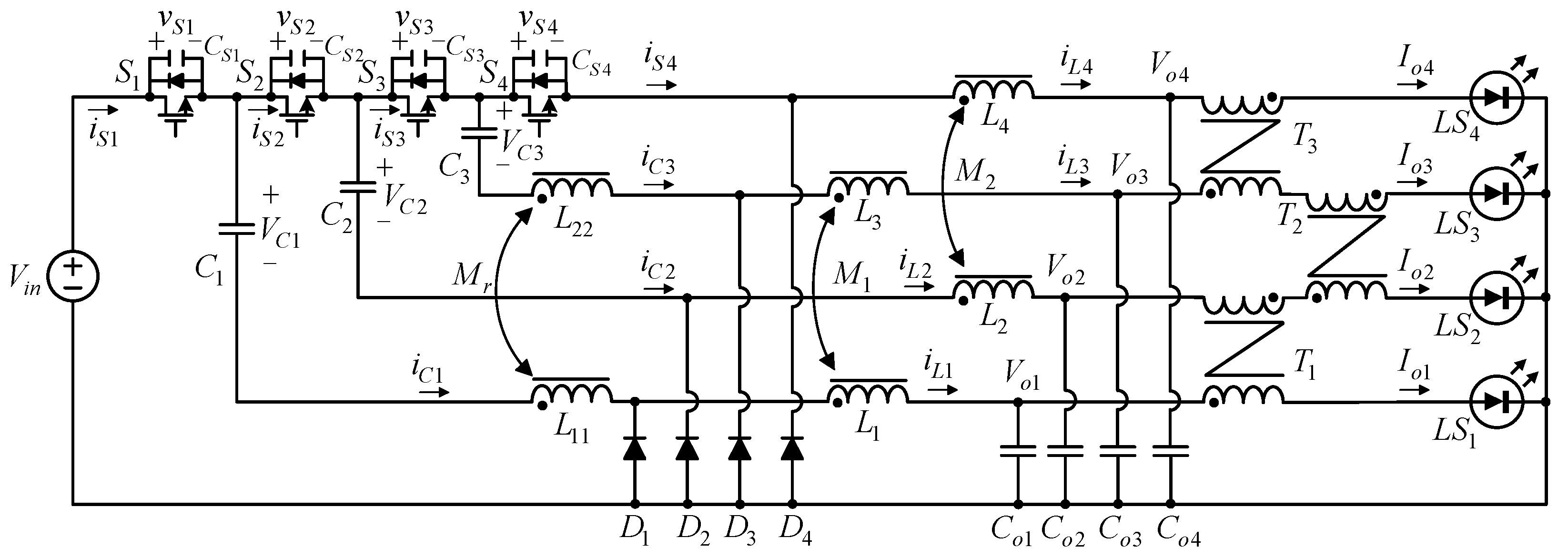
- Vin is the input voltage.
- (2)
- The currents flowing through LS1, LS2, LS3 and LS4 are Io1, Io2, Io3 and Io4, respectively. Under ideal conditions, Io1 = Io2 = Io3 = Io4 = Io.
- (3)
- The values of the energy-transferring capacitors C1, C2, and C3 and the output capacitors Co1, Co2, Co3 and Co4 are large enough to make the voltages across them constant, which will be regarded as voltage sources in the analysis.
- (4)
- Assume that the values of the four self-inductors in M1 and M2 are equal—that is, L1 = L2 = L3 = L4; assume that the values of the two self-inductors in Mr are equal—that is, L11 = L22.
- (5)
- Assume that the values of the two mutual inductors M1 and M2 are equal—that is, M1 = M2 = k1L1, where k1 is one coupling coefficient; assume that the mutual inductance Mr= k2L11, where k2 is the other coupling coefficient.
- (6)
- iS1, iS2, iS3 and iS4 are the currents flowing through S1, S2, S3 and S4, respectively; iL1, iL2, iL3 and iL4 are the currents flowing through L1, L2, L3 and L4, respectively; iC1, iC2, iC3 and iC4 are the currents flowing through C1, C2, C3 and C4, respectively; iD1, iD2, iD3 and iD4 are the currents flowing through D1, D2, D3 and D4, respectively.
- (7)
- vLr1 and vLr2 are the voltages across L11 and L22, respectively; vL1, vL2, vL3 and vL4 are the voltages across L1, L2, L3 and L4, respectively; vS1, vS2, vS3 and vS4 are the voltages across S1, S2, S3 and S4, respectively; vD1, vD2, vD3 and vD4 are the voltages across D1, D2, D3 and D4, respectively; VC1, VC2 and VC3 are the voltages across C1, C2 and C3, respectively.
- (8)
- Ts is the switching period; fs is the switching frequency.
- (9)
- The turn-on times of S1, S2, S3 and S4 are D1Ts, D2Ts, D3Ts and D4Ts, respectively. This circuit adopts a complementary gate driving method, so the duty cycle D1 = D3 = D, D2 = D4 = 1 − D. In addition, there are two blanking times between S1 and S2 over one switching cycle.
- (10)
- All the diodes, inductors and capacitors are regarded as ideal components.
- (11)
- vgs1, vgs2, vgs3 and vgs4 are gate driving signals for the four switches S1, S2, S3 and S4, respectively.
- (12)
- CS1, CS2, CS3 and CS4 are the parasitic capacitances on the four switches S1, S2, S3 and S4, respectively, where CS1 = CS2 = CS3 = CS4 = Coss, ideally.
- (13)
- T1, T2, and T3 are differential-mode transformers, and under ideal conditions, their permeability coefficients are regarded as infinite. Since the four output currents are the same, the sum of the magneto-motive force on each differential-mode transformer will be zero, so the effects of these transformers are ignored in the analysis.
- (14)
- The circuit operates in the continuous conduction mode (CCM), and there are ten operating states over one switching cycle, as shown in Figure 4.
- (15)
- Assume k1 = k2 = 1; then, Leq1 = Leq2 = Leq3 = Leq4 = 2L1 and Lr1 = Lr2 = 2L11 are as shown in Figure 5.
- (16)
2.2. Operating Principle Analysis
2.3. Output Voltage Derivation
2.4. Soft Switching Analysis
3. Specification Considerations
4. Results and Discussion
4.1. Experimental Results
4.2. Current Sharing Error Percentage
4.3. Extension of Number of LED Strings
4.4. Cost Comparison
5. Conclusions
Author Contributions
Funding
Institutional Review Board Statement
Informed Consent Statement
Data Availability Statement
Conflicts of Interest
References
- Liu, P.-J.; Hsu, Y.-C.; Hsu, S.-R. Drain-voltage balance and phase-shifted PWM control schemes for high-efficiency parallel-string dimmable LED drivers. IEEE Trans. Ind. Electron. 2018, 65, 6168–6176. [Google Scholar] [CrossRef]
- Kim, H.-C.; Yoon, C.S.; Jeong, D.-K.; Kim, J. A single-inductor, multiple-channel current-balancing LED driver for display backlight applications. IEEE Trans. Ind. Appl. 2014, 50, 4077–4081. [Google Scholar] [CrossRef]
- Zhao, R.; Zhang, J. High efficiency hybrid current balancing method for multi-channel LED drive. In Proceedings of the IEEE Applied Power Electronics Conference and Exposition, Charlotte, NC, USA, 15–19 March 2015; pp. 854–860. [Google Scholar]
- Hwu, K.I.; Chou, S.-C. A simple current-balancing converter for LED lighting. In Proceedings of the IEEE Applied Power Electronics Conference and Exposition, Washington, DC, USA, 15–19 February 2009; pp. 587–590. [Google Scholar]
- Hwu, K.I.; Tu, W.C.; Hong, M.J. A dimmable LED driver based on current balancing transformer with magnetizing energy recycling considered. IEEE J. Disp. Technol. 2014, 10, 388–395. [Google Scholar] [CrossRef]
- Lin, Y.L.; Chiu, H.J.; Lo, Y.K.; Leng, C.M. Light-emitting diode driver with a combined energy transfer inductor for current balancing control. IET Power Electron. 2015, 8, 1834–1843. [Google Scholar] [CrossRef]
- Hwu, K.I.; Jiang, W.Z.; Wu, P.Y. An expandable two-phase interleaved ultrahigh step-down converter with automatic current balance. IEEE Trans. Power Electron. 2017, 32, 9223–9237. [Google Scholar] [CrossRef]
- Liu, X.; Zhou, Q.; Xu, J.; Lei, Y.; Wang, P.; Zhu, Y. High-efficiency resonant LED backlight driver with passive current balancing and dimming. IEEE Trans. Ind. Electron. 2018, 65, 5476–5486. [Google Scholar] [CrossRef]
- Amiri, M.; Farzanehfard, H. A high-efficiency interleaved ultra-high step-down DC-DC converter with very low output current ripple. IEEE Trans. Ind. Electron. 2019, 66, 5177–5185. [Google Scholar] [CrossRef]
- Blewitt, W.M.; Gurwicz, D.I. Reduction of power MOSFET losses in hard-switched converters. IEEE Electron. Lett. 2008, 44, 1088–1089. [Google Scholar] [CrossRef]
- Alexakis, P.; Alatise, O.; Ran, L.; Mawby, P. Modeling power converters using hard switched silicon carbide MOSFETs and schottky barrier diodes. In Proceedings of the IEEE European Conference on Power Electronics and Applications, Lille, France, 2–6 September 2013; pp. 1–9. [Google Scholar]
- Yau, Y.-T.; Hwu, K.-I.; Shieh, J.-J. Soft switching of non-isolated buck-type converter with common-ground switch. Energies 2021, 14, 5290. [Google Scholar] [CrossRef]
- Feng, J.; Hu, Y.; Chen, W.; Chau-Chun, W. ZVS analysis of asymmetrical half-bridge converter. In Proceedings of the IEEE Power Electronics Specialists Conference, Vancouver, BC, Canada, 17–21 June 2001; pp. 243–247. [Google Scholar]
- Wu, X.; Zhang, J.; Ye, X.; Qian, Z. Analysis and derivations for a family ZVS converter based on a new active clamp ZVS cell. IEEE Trans. Ind. Electron. 2008, 55, 773–781. [Google Scholar] [CrossRef]
- Canesin, C.A.; Barbi, I. Novel zero-current-switching PWM converters. IEEE Trans. Ind. Electron. 1997, 44, 372–381. [Google Scholar] [CrossRef]
- Wakabayashi, F.; Canesin, C. A new family of zero-current-switching PWM converters and a novel HPF-ZCS-PWM boost rectifier. In Proceedings of the IEEE Applied Power Electronics Conference and Exposition, Dallas, TX, USA, 14–18 March 1999; pp. 605–611. [Google Scholar]
- Dudrik, J.; Spanik, P.; Trip, N.-D. Zero-voltageand zero-current switching full-bridge DC-DC converter with auxiliary transformer. IEEE Trans. Power Electron. 2006, 21, 1328–1335. [Google Scholar] [CrossRef]
- Amini, M.; Farzanehfard, H. Novel family of PWM soft-single-switched DC-DC converters with coupled inductors. IEEE Trans. Ind. Electron. 2009, 56, 2108–2114. [Google Scholar] [CrossRef]
- Yang, J.W.; Do, H.L. High-efficiency ZVS AC-DC LED driver using a self-driven synchronous rectifier. IEEE Trans. Circuits Syst. I Regul. Pap. 2014, 61, 2505–2512. [Google Scholar] [CrossRef]
- Xie, W.; Li, S.; Smedley, K.M.; Wang, J.; Ji, Y.; Yu, J. A family of dual resonant switched-capacitor converter with passive regenerative snubber. IEEE Trans. Power Electron. 2020, 35, 4891–4904. [Google Scholar] [CrossRef]
- Zheng, Y.; Brown, B.Y.; Xie, W.; Li, S.; Smedley, K. High step-up DC-DC converter with zero voltage switching and low input current ripple. IEEE Trans. Power Electron. 2020, 35, 9418–9431. [Google Scholar] [CrossRef]
- Soltanzadeh, K. Zero-current transition single-ended forward converter. IET Power Electron. 2020, 13, 1227–1235. [Google Scholar] [CrossRef]
- Yau, Y.-T.; Hwu, K.-I.; Tsai, Y.-D. Development of four-channel buck-type LED driver with automatic current sharing. Energies 2021, 14, 7844. [Google Scholar] [CrossRef]


| Name | Specifications |
|---|---|
| System Operating Mode | Rated Load: CCM Half Load: BCM Light Load: DCM |
| Rated Input Voltage (Vin) | 400 V |
| Rated Output Current per LED String (Io,rated) | 0.35 A |
| Minimum Output Current per LED String in CCM (Io,min,BCM) | 0.175 A |
| Minimum Output Current per LED String in DCM (Io,min,DCM) | 0.0875 A |
| Rated Output Power (Po,rated) | 38.64 W (4 Strings with 8 LEDs per String) |
| Minimum Output Power in CCM (Po,min,BCM) | 17.36 W |
| Minimum Output Power in DCM (Po,min,DCM) | 8.12 W |
| Switching Frequency (fs)/Period (Ts) |
| Name | Specifications |
|---|---|
| Forward Voltage (VF) | 2.95~3.85 V |
| DC Operating Current (IF,max) | 400 mA |
| Pulse Forward Current | 500 mA |
| Junction Temperature | 125 °C |
| Operating Temperature | −40~+85 °C |
| Typical Light Flux Output | 100 lm@350 mA |
| Component | Specifications |
|---|---|
| S1, S2, S3, S4 | IPA50R140CP |
| D1, D2, D3, D4 | DSEP8-02A |
| C1, C2, C3 | /400 V LTEC Electrolytic Capacitor |
| Co1, Co2, Co3, Co4 | /50 V Electrolytic Capacitor |
| Mr | Core: ACME PQ20/20 Lr1 = Lr2 = 200 μF |
| M1, M2 | Core: ACME PQ20/16 Leq1 = Leq2 = Leq3 = Leq4 = 600 μF |
| Gate Driver | TLP250H |
| Current Sensor | ACS712 |
| LED | EHP-AX08EL/GT01H-P01/5670/Y/K42 |
| LS1 | LS2 | LS3 | LS4 | ||
|---|---|---|---|---|---|
| 100% | Ion (mA) | 348 | 351 | 352 | 351 |
| en (%) | 0.71 | −0.14 | −0.43 | −0.14 | |
| 75% | Ion (mA) | 259 | 258 | 262 | 261 |
| en (%) | 0.38 | 0.77 | −0.77 | −0.38 | |
| 50% | Ion (mA) | 176 | 171 | 172 | 176 |
| en (%) | −1.29 | 1.58 | 1.01 | −1.29 | |
| 25% | Ion (mA) | 84.8 | 88.3 | 86.4 | 90.6 |
| en (%) | 3.11 | −0.89 | 1.29 | −3.51 |
| Component | Proposed | [23] | ||
|---|---|---|---|---|
| Specifications | Price (in USD) | Specifications | Price (in USD) | |
| MOSFETs | IPA50R140CP × 4 | (2.74/item) × 4 = 10.96 | SPA07N60C3 × 4 | (2.25/item) × 4 = 9.00 |
| Diodes | DSEP8-02A × 4 | (1.68/item) × 4 = 6.72 | DSEP8-02A × 4 | (1.68/item) × 4 = 6.72 |
| Electrolytic Capacitors | 47 μF/400 V × 3 220 μF/50 V × 4 | (2.68/item) × 3 = 8.04 (0.65/item) × 4 = 2.60 | 47 μF/400 V × 3 220 μF/50 V × 4 | (2.68/item) × 3 = 8.04 (0.65/item) × 4 = 2.60 |
| Cores | ACME PQ20/20 × 1 ACME PQ20/16 × 2 MA100 × 3 | (1.15/item) × 2 = 2.30 (1.03/item) × 2 = 2.06 (0.45/item) × 3 = 1.35 | ACME PQ20/16 × 4 | (1.03/item) × 4 = 4.12 |
| Total Price | 54.03 | Total Price | 30.48 | |
Publisher’s Note: MDPI stays neutral with regard to jurisdictional claims in published maps and institutional affiliations. |
© 2022 by the authors. Licensee MDPI, Basel, Switzerland. This article is an open access article distributed under the terms and conditions of the Creative Commons Attribution (CC BY) license (https://creativecommons.org/licenses/by/4.0/).
Share and Cite
Jiang, W.-Z.; Hwu, K.-I.; Shieh, J.-J. Four-Channel Buck-Type LED Driver with Automatic Current Sharing and Soft Switching. Appl. Sci. 2022, 12, 5842. https://doi.org/10.3390/app12125842
Jiang W-Z, Hwu K-I, Shieh J-J. Four-Channel Buck-Type LED Driver with Automatic Current Sharing and Soft Switching. Applied Sciences. 2022; 12(12):5842. https://doi.org/10.3390/app12125842
Chicago/Turabian StyleJiang, Wen-Zhuang, Kuo-Ing Hwu, and Jenn-Jong Shieh. 2022. "Four-Channel Buck-Type LED Driver with Automatic Current Sharing and Soft Switching" Applied Sciences 12, no. 12: 5842. https://doi.org/10.3390/app12125842
APA StyleJiang, W.-Z., Hwu, K.-I., & Shieh, J.-J. (2022). Four-Channel Buck-Type LED Driver with Automatic Current Sharing and Soft Switching. Applied Sciences, 12(12), 5842. https://doi.org/10.3390/app12125842