Article

Multi-Objective Optimization Design of 6-UPS Parallel Mechanism Based on Taguchi Method and Entropy-Weighted Gray Relational Analysis

1
College of Vehicle and Traffic Engineering, Henan University of Science and Technology, Luoyang 471003, China
2
School of Vehicle and Traffic Engineering, Henan Institute of Technology, Xinxiang 453000, China
*
Author to whom correspondence should be addressed.
Appl. Sci. 2022, 12(12), 5836; https://doi.org/10.3390/app12125836
Submission received: 21 April 2022 / Revised: 31 May 2022 / Accepted: 7 June 2022 / Published: 8 June 2022
(This article belongs to the Special Issue Soft Computing Application to Engineering Design)

Abstract

:
Nowadays, parallel mechanisms are widely used in many fields because of their excellent structural performance. In order to improve the comprehensive performance of 6-UPS parallel mechanism, this article proposes a multi-objective optimization design method for parallel mechanism based on the Taguchi method and entropy-weighted gray relational analysis (EGRA) method. By establishing a parametric model of the 6-UPS parallel mechanism, taking the peak force on the drive pair of the drive branch chain of the mechanism, the minimum value of the projection angle of the body-fixed coordinate system (BCS) relative to the inertial coordinate system (ICS), and the minimum value of the average projected angle of the BCS relative to the ICS as the objective functions, the relationship between the design variables and the objective function is investigated under the condition that the constraints are satisfied. Using the optimization method proposed in this article, the multi-objective optimization problem is transformed into a single-objective optimization problem based on gray relational grade (GRG). Compared with the non-optimized 6-UPS parallel mechanism, the simulation results show that the peak force on the drive pair of the drive branch chain is reduced by 17.73%, and the minimum value of the projected angle and the minimum value of the average projected angle of the BCS relative to the ICS are increased by 27.36% and 36.17%, respectively, which effectively improves the load-bearing capacity and motion range of the 6-UPS parallel mechanism and verifies the reliability of the optimized design method.

1. Introduction

With the advantages of simple structure, high positioning accuracy, and fast dynamic response, the parallel mechanism has been extensively used in the fields of advanced manufacturing equipment, national defense and military, automobile manufacturing, aerospace, and motion simulation [1,2,3]. In previous studies, researchers have explored parallel mechanisms from various aspects, especially in structural synthesis and design theory [4,5,6], kinematics and dynamics studies [7,8,9], singularity analysis [10,11,12], operation mode studies [13,14], and efficient control strategies [15,16]. These studies provide a deep foundation for the development of parallel mechanisms.
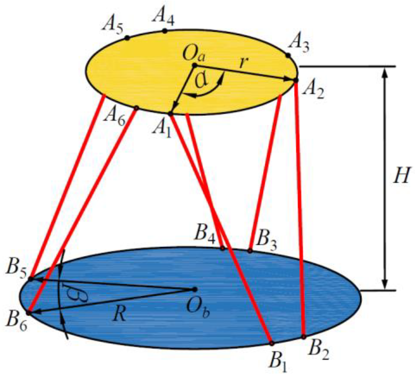
The main body of the 6-UPS parallel mechanism is composed of a mobile platform, a fixed platform, and six drive branch chains, where U stands for universal joint, P stands for prismatic pair, and S stands for spherical hinge. The 6-UPS parallel mechanism performance and its structural parameters are closely related. When the structural parameters are unreasonably designed, the mechanism’s performance will be significantly reduced. Therefore, researchers have also been working on the optimization design of the structure and performance of parallel mechanism, where the most commonly used optimization methods are divided into two categories: optimization methods based on objective functions and optimization methods based on performance atlas [17,18,19].
The optimization method based on objective function is to build up the objective function and constraints according to the optimization index and then use the optimization algorithm to search for the optimal solution. The optimization methods based on objective function are mostly used in the case of many parameter variables and too complex objective function. When there are two or more objective functions, it is called a multi-objective optimization problem, and solving a multi-objective optimization problem is a process of finding the Pareto optimal solution [20,21,22]. Qi et al. [23] conducted a multi-objective optimization of a typical parallel tracking mechanism under comprehensive consideration of the kinematics, stiffness, workspace, and dynamic performances, while considering manufacturing and assembly errors. Zhang et al. [24] used the PSO algorithm to perform multi-objective optimization of the workspace, dexterity, stiffness, energy efficiency, motion/force transfer efficiency, and inertial coupling index of the established 2RPU-2SPR super-constrained redundantly driven parallel mechanism. Mirshekari et al. [25] studied the effects of different parameters, such as the rotation joint angle and spherical joint position of the 6-RUS parallel robot mobile platform on the workspace, kinematics and dynamics indices, and they used the bees algorithm approach to optimize the manipulator structure.
The optimization method based on performance atlas refers to intuitively expressing the relationship between design indices and design parameters in a limited design space, so as to obtain the performance atlas of the mechanism. Liu and Wang [26] optimized the 3PRS mechanism and the spherical 5R parallel mechanism with 2-DOF by using the performance atlas method, so that they had better kinematic performance and force transmission performance in the workspace. Pan and Hou [27] conducted a comprehensive study on a mobile complex multi-body system, through mechanism analysis and identification, introducing sensitivity analysis and extracting key design variables from global variables for multi-objective optimization design. Wang et al. [28] took the motion/force transmissibility and the workspace range as the optimization objectives, respectively, expressing the relationship between the corresponding motion indices and structural parameters by using the performance atlas method and realized the optimal design of 3-PUU mechanism. However, there is a problem in the optimization method based on performance atlas, that is, when there are many characteristic parameters to be optimized, it cannot completely represent the performance atlas in a limited space.
In recent years, the approximate model technology has developed rapidly in multi-objective optimization [29,30]. By fitting the mathematical relationship between input and output, the approximate model technology can replace the real value with the predicted value of the approximate model within a certain error range, so as to effectively improve the calculation efficiency and simulation accuracy [31,32]. The widely used approximate models in engineering mainly include response surface method surrogate model, Kriging surrogate model, and radial basis function surrogate model [33,34]. Hu et al. [35] developed a Latin hypercube design, Kriging interpolation, and neural network training (LKN) method based on the response surface method, taking into account both kinematic and dynamic performance indices, carrying out the robustness design of the 4PUS-1RPU parallel mechanism.
The Taguchi method was initially created for quality engineering to assess and produce better robustness, tolerance specification, and quality management of production processes [36]. The Taguchi method does not rely on complex probabilistic or statistical analysis. It can mine the information of the whole parameter space through a little number of experiments to obtain the optimal solution of the experimental design [37,38]. Park et al. [39] performed kinematic optimization of a redundantly driven parallel mechanism using the Taguchi method with the optimization objective of maximizing the total of energy efficiency and workspace. Wu et al. [40] used the Taguchi method and Monte Carlo simulation method to optimize the 3-RRR parallel micro-movement platform iteratively and found the optimal geometric size of the flexure hinge. Shin et al. [41] proposed an optimization method using the Taguchi method to optimize the redundantly driven parallel mechanism by studying the kinematic parameters of a planar 2-DOF parallel robot; the optimal parameter combination between the link length and stiffness was obtained.
The multi-objective optimization design problem is driven by many competitive standards, and although optimization algorithm can provide designers with a large number of non-dominated optimal solutions, designers still need to use engineering knowledge to independently choose the best compromise solution [42]. Gray correlation analysis (GRA) has been widely used in various decision-making problems. Its basic idea is to use the linear interpolation between adjacent points of the sequence to map the discrete data to the geometry of the space and to determine the correlation between the sequences by calculating the distance between the reference sequence and the comparison sequence [43,44]. Dao and Huang [45,46] used optimization techniques, such as the Taguchi method, response surface method, GRA, and entropy weight measurement, to carry out a multi-objective optimization design for the 2-DOF flexible mechanism and the 2-DOF flexible mechanism with a modified double-lever amplification mechanism, respectively. Hsieh et al. [47] used the GRA method to design the mechanical structure of the conical guide mechanism to solve the interference misalignment problem during excavator attachment assembly.
However, traditional optimization methods are generally only suitable for linear and simple systems, and when they are applied to multi-objective optimization problems, there will be some limitations, such as difficulty in solving and global optimal solutions being ignored [48]. Although intelligent optimization methods outperform traditional optimization methods in solving multi-objective problems, they also have their own limitations, such as being time consuming and having poor convergence [49]. In order to solve this problem, many scholars try to develop new optimization methods, among which the hybrid algorithm can better combine the optimization efficiency and accuracy, so as to solve the multi-objective optimization problem [50,51]. In addition, it also has great application prospects in multi-objective optimization design by combining multiple optimization methods. Wang et al. [52] proposed an optimization method combining radial basis function neural network model, fuzzy subtractive clustering sequential sampling method, and NSGA-II, which is used to improve the calculation efficiency and accuracy of multi-objective optimization problems in engineering. Xiong et al. [53] proposed a hybrid method combining contribution analysis, radial basis function neural-network-response surface method hybrid surrogate modeling method, and PSO algorithm for lightweight design of body front-end structures.
The above studies have carried out multi-objective optimization design of parallel mechanism from different aspects, such as the optimization method based on objective function, optimization method based on performance atlas, approximate model technology, Taguchi method, and gray relational analysis method. In order to further improve the optimization efficiency of the parallel mechanism, on the basis of the above research, this article conducts a multi-objective optimization design of the 6-UPS parallel mechanism based on the parametric modeling technology, the Taguchi method, and entropy-weighted gray relational analysis (EGRA) method. The parametric model of a 6-UPS parallel mechanism is established by ADAMS software, and the validity and accuracy of the parametric model are verified by theoretical calculation. By studying the association between the design variables and the objective function, the multi-objective optimization problem of parallel mechanism is transformed into a single-objective optimization problem based on the gray relational grade (GRG) by using the EGRA method to realize the multi-objective optimal design of the load-bearing capacity and motion range of the 6-UPS parallel mechanism.

2. Multi-Objective Optimization Design Method

Based on parametric modeling technology, the Taguchi method, and the EGRA method, the optimization design of 6-UPS parallel mechanism in this article is mainly divided into five steps, and the optimization design process is shown in Figure 1.
Step 1: Parametric modeling and model validation. The key factors affecting the structural performance of 6-UPS parallel mechanism are found out through the mechanism configuration analysis, and then, the parametric model of the mechanism is created in ADAMS software, and the validity and accuracy of the parametric model are verified by comparing the simulation and theoretical calculation results.
Step 2: Establishing the mathematical model of optimal design. According to the structural parameters and expected structural performance of 6-UPS parallel mechanism, the mathematical models of design variables, objective functions, and constraints are created, and the corresponding design functions are established in ADAMS software.
Step 3: Research on the relationship between design variables and objective functions. By creating the motion law of the driving branch chain, the effect of a single design variable on the objective function is studied, so as to facilitate the subsequent transformation of the multi-objective problem into a single-objective optimization problem.
Step 4: Experiment design based on the Taguchi method. By studying the effect of a single design variable on the objective function, five factors and four levels are determined, and the experimental layout and optimization are carried out by the Taguchi method.
Step 5: EGRA obtains the optimal result. The GRG of each scheme in the Taguchi experimental design is obtained by GRA, and the optimization results are sorted. The average GRG of each design variable is obtained by factor effect analysis, and the optimal result is obtained.

3. Parametric Modeling and Model Validation

3.1. 6-UPS Parallel Mechanism Configuration Analysis

The 6-UPS parallel mechanism comprises a mobile platform, a fixed platform, drive branch chains, spherical hinge, and universal joint. Among them, the fixed platform is set on the base, the telescopic rod end of the drive branch chains is linked to the mobile platform by the spherical hinge, the cylinder end is linked to the fixed platform by the universal joint, and the drive branch chains are used as the driving input device of the mechanism, which enables the mobile platform to complete 6-DOF of movement in space through its respective independent telescopic movements: lateral movement, longitudinal movement, vertical movement, pitch, roll, and yaw.
The structure of the 6-UPS parallel mechanism is shown in Figure 2. Among them, Ai represents the position of the six spherical hinges; Bi represents the position of the six universal joints; r is the distribution circle radius of the geometric center of the spherical hinge of the mobile platform; R is the distribution circle radius of the geometric center of the universal joint of the fixed platform; α is the central angle corresponding to the long side of the spherical hinge; β is the central angle corresponding to the short side of the universal joint; H is the initial height between the center point Oa of the mobile platform and the center point Ob of the fixed platform.

3.2. Parametric Model Creation

The parametric model of the 6-UPS parallel mechanism is established by ADAMS software. The parametric model is based on parameterizing the point coordinates, and the model can be updated automatically by changing only the parameters of the design variables when modifying the model, so as to research the relevant performance of the parallel mechanism under various parameters. The parameterized point coordinates of the mechanism are shown in Table 1.
After the parametric points are created, the corresponding structural components are produced according to Figure 2; the spherical pair and the universal pair are added to the spherical hinge and the universal joint, respectively, and the moving pair is added to the drive branch chain. The parametric model of the mechanism created is shown in Figure 3.

3.3. Parametric Model Validation

Although the structural parameters of the model can be changed quickly through parametric modeling, unverified models can lead to unreliable designs. Therefore, it is essential to compare the simulation test results with the theoretical calculation results to verify the validity of the parametric model before the optimization design is carried out.
Selecting the drive branch chain as the research object, when the distribution circle radius r of the geometric center of the spherical hinge of the mobile platform and the distribution circle radius R of the geometric center of the universal joint of the fixed platform are known, the position vector Ai at the connection between the mobile platform and the spherical hinge and the position vector Bi at the connection between the fixed platform and the universal joint can be represented on the respective coordinate systems to determine the length vector Li of the drive branch chain.
L i = R A i + E i B i   i = 1 , 2 , , 6
where Li is the length vector of the drive branch chain; R is the rotation transformation matrix obtained after three rotation transformations; Ai is the position vector at the connection between the mobile platform and the spherical hinge; Ei is the unit matrix; Bi is the position vector at the connection between the fixed platform and the universal joint.
The coordinate transformation diagram of the mechanism is shown in Figure 4. Among them, the body-fixed coordinate system (BCS) Oa-XaYaZa on the mobile platform can be regarded as obtained by the inertial coordinate system (ICS) Ob-XbYbZb on the fixed platform after three translations and three rotations.
The ICS is translated in the order along the X axis, Y axis, and Z axis, so that the origin Ob of the ICS coincides with the origin Oa of the BCS to obtain the translation transformation matrix T:
T = x y z T
where x, y, and z are the displacements of the BCS relative to the X, Y, and Z axes of the ICS, respectively.
The ICS is rotated in the order around the X axis, Y axis, and Z axis, so that the coordinate axes of the ICS and the BCS are completely coincident to obtain the rotation transformation matrix R:
R = c γ c ψ c γ s ψ s φ s γ c φ s γ s φ + c φ c γ s ψ s γ c ψ c γ c φ s φ s γ s ψ s γ s ψ c φ c γ s φ s ψ c ψ s φ c ψ c φ
where s represents the sine function sin x; c represents the cosine function cos x; φ, ψ, and γ are the rotation angles of the BCS relative to the X, Y, and Z axes of the ICS, respectively.
Let Ai be the absolute coordinates of the spherical hinge on the mobile platform and Bi be the absolute coordinates of the universal joint on the fixed platform, then
A i = x i a y i a z i a T B i = x i b y i b z i b T i = 1 , 2 , , 6
Substitute into Formula (1) to obtain
L i = l i x l i y l i z = c γ c ψ x i a + c γ s ψ s φ s γ c φ y i a + s γ s φ + c φ c γ s ψ z i a + E i x x i b s γ c ψ x i a + c γ c φ s φ s γ s ψ y i a + s γ s ψ c φ c γ s φ z i a + E i y y i b s ψ x i a + c ψ s φ y i a + c ψ c φ z i a + E i z z i b i = 1 , 2 , , 6
Add a multi-DOF drive at the center Oa of the mobile platform of the 6-UPS parallel mechanism; the translational drive along the X, Y, and Z axes is Tx = Ty = Tz = 60 sin (0.5πt), and the rotational drive around the X, Y, and Z axes is Rx = Ry = Rz = 0.
Substituting the values into l i = l i x 2 + l i y 2 + l i z 2 , the theoretical variation curve of the displacement of each drive branch chain is obtained by solving. The simulation and theoretical comparison results of each drive branch chain are shown in Figure 5.
As can be seen from Figure 5, the simulation results of the displacement of each drive branch chain in the 6-UPS parallel mechanism basically match the theoretical calculation results, and the curve is smooth without sudden change, although there is a certain error, but the maximum error is 1.65%, and the motion trend and direction of both are highly consistent, thus verifying the validity and accuracy of the parameterized model.

4. Mathematical Model for Optimal Design

4.1. Design Variable Creation

According to the actual application purpose of the 6-UPS parallel mechanism, the expected load-bearing capacity and the expected operating space, and other requirements, the design variables of the 6-UPS parallel mechanism are expressed as
x = x 1 , x 2 , x 3 , x 4 , x 5 T = r , R , α , β , H T
where xi (i = 1, 2,…, 5) is the design variable; r is the distribution circle radius of the geometric center of the spherical hinge of the mobile platform; R is the distribution circle radius of the geometric center of the universal joint of the fixed platform; α is the central angle corresponding to the long side of the spherical hinge; β is the central angle corresponding to the short side of the universal joint; H is the initial height between the center point Oa of the mobile platform and the center point Ob of the fixed platform.
In Formula (6), the design variables are independent of each other, and the value range of the design variables is shown in Table 2.

4.2. Objective Function Creation

In order to improve the load-bearing capacity of the 6-UPS parallel mechanism and expand the motion range of the mechanism, this article takes the peak force on the drive pair of the drive branch chain, the minimum value of the projection angle of the BCS relative to the ICS, and the minimum value of the average projected angle of the BCS relative to the ICS is used as the optimization objectives, that is, when the load on the mobile platform is identical to the movement law of the six drive branch chain, the peak force on the drive pair of the six drive branch chain is the smallest, and the minimum value of projected angle and the average projected angle of the BCS relative to the ICS are the largest.
Therefore, the objective function of the multi-objective optimization design of the 6-UPS parallel mechanism is
F x = min f 1 x , max f 2 x , max f 3 x f 1 x = max F 1 , F 2 , F 3 , F 4 , F 5 , F 6 f 2 x = min φ , ψ , γ f 3 x = min φ + ψ + γ ¯
where f1(x) is the peak force on the drive pair of the drive branch chain; f2(x) is the minimum value of the projection angle of the BCS relative to the ICS; f3(x) is the minimum value of the average projected angle of the BCS relative to the ICS; F1~F6 are the force values of the drive pair of each drive branch chain; φ, ψ, and γ are the rotation angles of the BCS relative to the X, Y, and Z axes of the ICS, respectively.

4.3. Constraint Creation

To better ensure the comprehensive performance of the 6-UPS parallel mechanism in the optimization process, in addition to the objective function, the displacement of the prismatic pair of the drive branch chain, the rotation angle of the spherical pair and the universal pair, and the interference of the drive branch chain are used as constraints in the optimization process.
The telescopic length of the drive branch chain determines the stroke range of the prismatic pair, and the displacement constraint of the prismatic pair is expressed as
P min P i P max
where Pmin is the minimum displacements allowed by the prismatic pair, Pmin = −300 mm; Pmax is the maximum displacements allowed by the prismatic pair, Pmax = 300 mm.
The rotation angle θi of the spherical pair and the universal pair cannot exceed its maximum allowable rotation angle θmax, whose constraint is expressed as
θ i = arccos L i σ n i L i θ max
where Li is the length vector of the drive branch chain; σ is the attitude of the hinge point relative to the ICS; ni is the Z axis vector of the ith hinge point; θmax is the maximum allowable rotation angle, θmax = 30°.
Due to the physical dimensions of the drive branch chains, interference may occur between the branch chains when the mechanism is in motion. Assuming that each drive branch chain is cylindrical, and its diameter is D, the constraint that the drive branch chain does not interfere is expressed as
D D i
where Di is the shortest distance between two adjacent centerlines.

5. Effect of Design Variables on the Objective Function

5.1. Motion Law of the Drive Branch Chain

To enable the 6-UPS parallel mechanism to complete the translational movement along the X, Y, and Z axes and the rotational movement around the X, Y, and Z axes in a cycle, the drive values in Table 3 are applied to the prismatic pairs of the six drive branch chains.

5.2. Effect of the Distribution Circle Radius of the Geometric Center of the Spherical Hinge of the Mobile Platform on the Objective Function

The effect of the distribution circle radius of the geometric center of the spherical hinge of the mobile platform on the objective function is studied in ADAMS software. The variation curve of the objective function with the distribution circle radius r of the geometric center of the spherical hinge of the mobile platform is shown in Figure 6.
As can be seen from Figure 6, the objective functions f1(x), f2(x), and f3(x) are negatively correlated with the design variables. With the increase in the distribution circle radius of the geometric center of the spherical hinge of the mobile platform, the performance of the objective function f1(x) is gradually enhanced, while the performance of the objective functions f2(x) and f3(x) is gradually reduced.

5.3. Effect of the Distribution Circle Radius of the Geometric Center of the Universal Joint of the Fixed Platform on the Objective Function

The effect of the distribution circle radius of the geometric center of the universal joint of the fixed platform on the objective function is studied in ADAMS software. The variation curve of the objective function with the distribution circle radius R of the geometric center of the universal joint of the fixed platform is shown in Figure 7.
As can be seen from Figure 7, the objective functions f1(x) and f2(x) are positively correlated with the design variables within a certain range, and the objective function f3(x) is negatively correlated with the design variables within a certain range. With the increase in the distribution circle radius of the geometric center of the universal joint of the fixed platform, the performance of the objective functions f1(x) and f3(x) is gradually reduced, while the performance of the objective function f2(x) is gradually enhanced.

5.4. Effect of the Central Angle Corresponding to the Long Side of the Spherical Hinge on the Objective Function

The effect of the central angle corresponding to the long side of the spherical hinge on the objective function is studied in ADAMS software. The variation curve of the objective function with the central angle α corresponding to the long side of the spherical hinge is shown in Figure 8.
As can be seen from Figure 8, the objective function f1(x) is positively correlated with the design variables, and the objective functions f2(x) and f3(x) are negatively correlated with the design variables. With the increase in the central angle corresponding to the long side of the spherical hinge, the performance of the objective functions f1(x), f2(x), and f3(x) is gradually reduced.

5.5. Effect of the Central Angle Corresponding to the Short Side of the Universal Joint on the Objective Function

The effect of the central angle corresponding to the short side of the universal joint on the objective function is studied in ADAMS software. The variation curve of the objective function with the central angle β corresponding to the short side of the universal joint is shown in Figure 9.
As can be seen from Figure 9, the objective function f1(x) is negatively correlated with the design variables; the objective function f2(x) is negatively correlated with the design variables first and is then positively correlated; and the objective function f3(x) is positively correlated with the design variables. With the increase in the central angle corresponding to the short side of the universal joint, the performance of the objective functions f1(x) and f3(x) is gradually enhanced, and the performance of the objective function f2(x) is gradually reduced at first and then progressively enhanced.

5.6. Effect of the Initial Height between the Mobile and Fixed Platform on the Objective Function

The effect of the initial height between the mobile and fixed platform on the objective function is studied in ADAMS software. The variation curve of the objective function with the initial height H between the mobile and fixed platform is shown in Figure 10.
As can be seen from Figure 10, the objective functions f1(x) and f2(x) are negatively correlated with the design variables, and the objective function f3(x) is positively correlated with the design variables. As the initial height increases, the performance of the objective functions f1(x) and f3(x) is gradually enhanced, and the performance of the objective function f2(x) is gradually reduced.

6. Experimental Scheme Design and Optimization Results Discussion

6.1. Experiment Design Based on Taguchi Method

The Taguchi method is an effective mathematical-statistical method, which can mine the information of the whole parameter space through a little number of experiments. The basic steps for using the Taguchi method for experimental design are as follows:
(a)
Identifying the objectives: In the Taguchi method, the specific optimization objective should be defined first, which determines the objective function and influences the classification of variables into controllable factors and noise factors.
(b)
Determining the objective function: Divide the objective function according to three different types: nominally the best, the smaller the better, and the larger the better.
(c)
Selection of controllable factor and noise factor: In the Taguchi method, the controllable factor is determined during the design process, while the noise factor varies according to the conditions of users.
(d)
Selecting an orthogonal array: The orthogonal array can obtain quasi-optimal results without spending a lot of time and uses independent factor impact analysis to reduce computational optimization.
(e)
Simulation and analysis: The analysis phase of the simulation consists of converting the raw data of the objective function into the computation of a representative signal-to-noise ratio, which serves as a measurement tool to determine robustness and is an important factor in optimizing design parameters.
Through the study of the 6-UPS parallel mechanism, five design variables, as shown in Table 2, are determined, which are the main factors affecting the load-bearing capacity and motion range of the mechanism. When different levels of each factor are combined, the mechanism’s performance will change. Therefore, the optimization of the 6-UPS parallel mechanism is a multi-objective, multi-factor, and multi-level problem. The Taguchi experimental design used in this article includes five factors and four levels L16 (45); the levels of every factor are shown in Table 4; and the experimental layout and experimental results are shown in Table 5.

6.2. Gray Relational Grade

The GRA is a method proposed by Deng [54] in 1982 that uses GRG to represent the grade of approximation between design scheme and ideal scheme, which provides an effective mathematical method for dealing with problems of inadequate information, indigent information, and uncertain information. Due to the order of magnitude difference, the experimental results in Table 5 need to be preprocessed before gray correlation analysis. According to the characteristics of the corresponding data, the experimental results are scaled to between 0 and 1 using the different normalization methods.
If the objective has the feature of ‘bigger is better’, the normalization method is expressed as
x i * k = x i k min k   x i k max k   x i k min k   x i k
If the objective has the feature of ‘smaller is better’, the normalization method is expressed as
x i * k = max k   x i k x i k max k   x i k min k   x i k
where x i * k is the normalized value of the ith response in the kth objective function; xi(k) is the initial value of the objective function; maxkxi(k) and minkxi(k) are the maximum and minimum values of the kth objective function, respectively.
The above normalization method is also called ‘gray generation’, and the corresponding gray relational coefficient (GRC) is calculated as
γ x 0 * k , x i * k = Δ min + ζ Δ max Δ 0 i k + ζ Δ max
where x 0 * k is the ideal experimental scheme defined by ideal; x i * k is the designed experimental scheme; Δ0i(k) is the absolute difference between x 0 * k and x i * k ; Δmax and Δmin are the maximum and minimum values of Δ0i(k), respectively; ζ is the discrimination coefficient, ζ [0, 1].
In this article, x 0 * k = 1 is selected as the reference result, and the GRC of the experimental results is shown in Table 6.
The GRG is calculated by weighted summation of the GRC of each objective function, and the calculation formula of GRG is
Γ x 0 * , x i * = k = 1 n ω k γ x 0 * k ,   x i * k
where n is the number of objective functions; ωk is the weight coefficient of the kth objective function, k = 1 n ω k = 1 .
Usually, since the importance of each objective response may be different, their weights can be calculated by the information entropy representing the uncertainty degree of the random variable, and the information entropy of the kth objective function is as follows:
e k = 1 ln m i = 1 m x ik i = 1 m x ik ln x ik i = 1 m x ik
where m is the number of responses, i = 1, 2, … m; n is the number of objective functions, k = 1, 2, … n; xik is the normalized value of the ith response in the kth objective function.
The weight coefficient of the objective function can be calculated as
ω k = d k k = 1 n d k
where dk is the degree of deviation of the kth objective function, dk = 1 − ek.
The weights of the objective functions f1(x), f2(x), and f3(x) are obtained through calculation as 0.36, 0.32, and 0.32, respectively. The GRG and ranking of each experimental result are shown in Table 7.
The greater the GRG, the closer the design parameters are to the best combination. Therefore, it can be seen from Table 7 that the 15th experiment among the 16 experiments provides the optimal solution for the multi-objective optimization problem of 6-UPS parallel mechanism.

6.3. Factor Effect Analysis

In GRA, the average GRG of each factor level is a significant indicator to determine the best combination of design parameters. The GRG is classified according to the identical level of each column of design parameters in the Taguchi array, and the average GRG is calculated for each factor at the same level.
Taking the average GRG of each level of the α factor as an example, the third column in Table 5 shows that the factor α level in the 1st, 6th, 11th, and 16th experiments performed is level 1, and the corresponding value of GRG is the result listed in Table 7. For level 1 of factor α, the GRG of the 1st, 6th, 11th, and 16th experiments are 0.5343, 0.3994, 0.5379, and 0.6203, respectively. Therefore, the level 1 (α1) average GRG of factor α is
α 1 = 0.5343 + 0.3994 + 0.5379 + 0.6203 / 4 = 0.5229
Similarly, the average GRG of α2, α3, and α4 are 0.5466, 0.4968, and 0.4529, respectively. The same method is used to calculate all average GRG for each factor level, and the calculation results are shown in Table 8.
As can be seen from Table 8, the maximum values of the average GRG of the factors H, β, α, R, and r are H4, β3, α2, R1, and r1, respectively. Therefore, the performance of the mechanism is optimal when the structural parameters of the 6-UPS parallel mechanism H = 1100 mm, β = 30°, α = 85°, R = 800 mm, and r = 500 mm. In addition, in Table 8, the absolute deviation between the maximum and minimum value of the average GRG of factor H is the largest. Therefore, factor H has the most excellent effect on the load-bearing capacity and motion range of the 6-UPS parallel mechanism, followed by factors r, α, β, and R.
The effects of different levels of each factor on the multi-objective performance are shown in Figure 11. From the slopes of each factor curve in Figure 11, it can be seen that the initial height H between the mobile and fixed platform has a positive effect on the performance of the 6-UPS parallel mechanism; the distribution circle radius r of the geometric center of the spherical hinge of the mobile platform has a negative effect on the performance of the 6-UPS parallel mechanism, while other factors have an uncertain effect on the performance of the 6-UPS parallel mechanism.

6.4. Discussion of Optimization Results

Based on the optimized combination of design parameters, the multi-objective optimized design of the 6-UPS parallel mechanism is completed. Verify the effectiveness of the optimized design by comparing the mechanism’s performance before and after optimization. The force on the drive pair of the six drive branch chains before and after optimization is shown in Figure 12.
It can be seen from Figure 12a–f that the force change trend of the drive pair of the six drive branch chains before and after optimization has a good consistency, and the peak force on the drive pair of each drive branch chain is significantly reduced after optimization. Before and after the optimization design, the peak force on the drive pair of the drive branch chain is shown in Table 9. Combined with Figure 12a–f, the peak force on the drive pair before the optimization of the 6-UPS parallel mechanism appears at the drive branch chain 5, which is 17.922 N; the peak force on the drive pair after optimization appears at the drive branch chain 2, which is 14.744 N, and the improvement rate reaches 17.73%.
The change of the minimum value of the projected angle of the BCS relative to the ICS before and after optimization is shown in Figure 13.
It can be seen from Figure 13a–c that the variation trend of the minimum value of the projection angle of the BCS relative to the ICS on the X, Y, and Z axes before and after optimization has a good consistency, and the minimum value of the projection angle and the minimum value of the average projected angle are significantly improved after optimization. Before and after the optimization design, the minimum value of the projection angle of the BCS relative to the ICS on the X axis is 1.919° and 2.444°, respectively, which appears at 8.35 s and 8.30 s, respectively; the minimum value of the projection angle of the BCS relative to the ICS on the Y axis is 2.449° and 2.800°, respectively, which appears at 4.65 s and 4.70 s, respectively; the minimum value of the projection angle of the BCS relative to the ICS on the Z axis is 3.188° and 5.048°, respectively, both appearing at 6.95 s. Combined with Figure 13a–c, the minimum value of the projection angle before and after optimization of the 6-UPS parallel mechanism is on the X axis, which is 1.919° and 2.444°, respectively, with an improvement rate of 27.36%; the minimum value of the average projected angle before optimization is 2.519°, and after optimization, 3.430°, with an improvement rate of 36.17%.
To reflect more instinctively the motion range before and after optimization of the 6-UPS parallel mechanism, the position parameters of the position vector Ai at the connection between the mobile platform and the spherical hinge and the position vector Bi at the connection between the fixed platform and the universal joint in the 6-UPS parallel mechanism are input into the MATLAB software for programing and solving, and the workspace before and after optimization of the 6-UPS parallel mechanism is obtained as shown in Figure 14, Figure 15, Figure 16 and Figure 17.
It can be seen from Figure 14, Figure 15, Figure 16 and Figure 17 that the motion range of the optimized 6-UPS parallel mechanism extends to different degrees in the X, Y, and Z axes, and the motion range in the X axis is changed from [−196.89, 196.89] to [−242.20, 242.20]; the motion range in the Y axis is changed from [−171.03, 171.03] to [−212.18, 212.18]; the motion range in the Z axis is changed from [896.91, 1058.93] to [1021.70, 1185.63], and the motion range of the mechanism is significantly expanded.

7. Conclusions

In this article, the multi-objective optimization design of the 6-UPS parallel mechanism is carried out based on the parametric modeling technology, the Taguchi method and EGRA method. The parametric model of the 6-UPS parallel mechanism is established by ADAMS software, and the validity and accuracy of the parametric model are verified by theoretical calculation. The relationship between the design variables and the objective function is investigated by establishing the design variables, objective function, and constraints of the mechanism. Combining the Taguchi method and EGRA method, the multi-objective optimization problem is transformed into a single-objective optimization problem based on the GRG. The best combination of five design variables is determined through factor effect analysis. After the optimized design of the 6-UPS parallel mechanism, the peak force on the drive pair of the drive branch chain is reduced by 17.73%, and the minimum value of the projected angle and the minimum value of the average projected angle of the BCS relative to the ICS are increased by 27.36% and 36.17%, respectively, which significantly improves the load-bearing capacity of the 6-UPS parallel mechanism and expands the motion range of the mechanism.
To sum up, the method proposed in this article attempts to solve multi-objective optimization problems, such as nonlinear and large displacement. Since the multi-objective problem is transformed into a single-objective problem, good results can be obtained when solving nonlinear and complex optimization problems, and computing costs can be significantly reduced. Compared with other multi-objective optimization methods, the method proposed in this article is simpler and more convenient and can be efficiently used in the optimal design of multi-parameter parallel mechanisms, which has certain guiding significance for solving practical engineering problems. In the future, adding more experimental sequences to the experimental design, combining more effective optimization methods, or combining approximate model technology can obtain better optimization results.

Author Contributions

Conceptualization, H.S., X.C. and S.Z.; methodology, H.S. and S.Z.; software, H.S.; validation, H.S. and X.C.; formal analysis, H.S., X.C. and S.Z.; writing—original draft preparation, H.S. and X.C.; writing—review and editing, X.C., S.Z. and L.X.; visualization, H.S.; supervision, X.C., S.Z. and L.X.; project administration, S.Z. and L.X.; funding acquisition, S.Z. and L.X. All authors have read and agreed to the published version of the manuscript.

Funding

This research was funded by the National Key Research and Development Program of China, grant number 2017YFD070020402; the Key Scientific Research Project of Colleges and Universities in Henan Province, grant number 20A460013; and the Young Talent Support Project in Henan Province, grant number 2020HYTP016.

Institutional Review Board Statement

Not applicable.

Informed Consent Statement

Not applicable.

Data Availability Statement

Not applicable.

Conflicts of Interest

The authors declare no conflict of interest.

References

  1. Li, C.Y.; Wu, H.P.; Eskelinen, H. Design and multi-objective optimization of a dexterous mobile parallel mechanism for fusion reactor vacuum vessel assembly. IEEE Access 2021, 9, 153796–153810. [Google Scholar] [CrossRef]
  2. Xie, Y.; Li, Y.; Chi, C.F.; Zhu, Z.; Chen, X. Design and analysis of a novel compact XYZ parallel precision positioning stage. Microsyst. Technol. 2020, 27, 1925–1932. [Google Scholar] [CrossRef]
  3. Katsushi, F.; Michio, S.; Ryusei, K. Nanometre-cutting machine using a Stewart-platform parallel mechanism. Meas. Sci. Technol. 2004, 15, 467–474. [Google Scholar] [CrossRef]
  4. Liu, Y.; Han, X.; Guo, Z.; Jia, X. Structure and kinematics analysis of a novel 4-RPTR parallel mechanism. China Mech. Eng. 2010, 23, 2812–2815, 2820. [Google Scholar] [CrossRef]
  5. Kang, D.S.; Seo, T.W.; Kim, J. Development and kinematic calibration for measurement structure of a micro parallel mechanism platform. J. Mech. Sci. Technol. 2008, 22, 746–754. [Google Scholar] [CrossRef]
  6. Tang, X.Y.; Chen, I.M.; Li, Q. Design and nonlinear modeling of a large-displacement XYZ flexure parallel mechanism with decoupled kinematic structure. Rev. Sci. Instrum. 2006, 77, 115101. [Google Scholar] [CrossRef]
  7. Piccin, O.; Bayle, B.; Maurin, B.; Mathelin, M.D. Kinematic modeling of a 5-DOF parallel mechanism for semi-spherical workspace. Mech. Mach. Theory 2009, 44, 1485–1496. [Google Scholar] [CrossRef]
  8. Zhang, D.S.; Xu, Y.D.; Yao, J.T.; Hu, B.; Zhao, Y.S. Kinematics, dynamics and stiffness analysis of a novel 3-DOF kinematically/actuation redundant planar parallel mechanism. Mech. Mach. Theory 2017, 116, 203–219. [Google Scholar] [CrossRef]
  9. Wang, S.C.; Hikita, H.; Kubo, H.; Zhao, Y.S.; Huang, Z.; Ifukube, T. Kinematics and dynamics of a 6 degree-of-freedom fully parallel manipulator with elastic joints. Mech. Mach. Theory 2003, 38, 439–461. [Google Scholar] [CrossRef]
  10. Monsarrat, B. Singularity analysis of a Three-leg Six-degree-of-freedom parallel platform mechanism based on grassmann line geometry. Int. J. Robot. Res. 2001, 20, 312–328. [Google Scholar] [CrossRef]
  11. Kim, J.S.; Park, J.H. Geometric singularity avoidance of a 3-SPS/S parallel mechanism with redundancy using conformal geometric algebra. J. Korean Soc. Precis. Eng. 2015, 32, 253–261. [Google Scholar] [CrossRef]
  12. Laryushkin, P.; Glazunov, V.; Erastova, K. On the maximization of joint velocities and generalized reactions in the workspace and singularity analysis of parallel mechanisms. Robotica 2019, 37, 675–690. [Google Scholar] [CrossRef]
  13. Nurahmi, L.; Gan, D.M. Reconfiguration of a 3-(rR)PS metamorphic parallel mechanism based on complete workspace and operation mode analysis. J. Mech. Robot. 2020, 12, 011002. [Google Scholar] [CrossRef]
  14. Nurahmi, L.; Caro, S.; Wenger, P.; Schadlbauer, J.; Husty, M. Reconfiguration analysis of a 4-RUU parallel manipulator. Mech. Mach. Theory 2015, 96, 269–289. [Google Scholar] [CrossRef] [Green Version]
  15. Shen, G.; Li, G.; Zang, W.S.; Li, X.; Tang, Y. Modal space feedforward control for electro-hydraulic parallel mechanism. IEEE Access 2019, 7, 39751–39761. [Google Scholar] [CrossRef]
  16. Sun, S.W.; Wu, N.; Zheng, G.; Wang, X.H.; Xia, H.X. Research and implementation on control technology of plane two-DOF dual-truck parallel mechanism. In Proceedings of the 2011 IEEE International Conference on Mechatronics and Automation, Beijing, China, 7–10 August 2011; pp. 1682–1687. [Google Scholar] [CrossRef]
  17. Huang, G.Y.; Guo, S.; Zhang, D.; Qu, H.B.; Tang, H.Y. Kinematic analysis and multi-objective optimization of a new reconfigurable parallel mechanism with high stiffness. Robotica 2017, 36, 187–203. [Google Scholar] [CrossRef]
  18. Wu, M.L.; Zhang, Y.; Yue, X.Q.; Lv, D.Y.; Chen, M.; Wang, X.H.; Zhang, J. Optimal design of an asymmetrical parallel mechanism. Proc. Inst. Mech. Eng. Part C-J. Eng. Mech. Eng. Sci. 2021, 235, 6922–6939. [Google Scholar] [CrossRef]
  19. Gao, Z.; Zhang, D. Workspace representation and optimization of a novel parallel mechanism with Three-degrees-of-freedom. Sustainability 2011, 3, 2217–2228. [Google Scholar] [CrossRef] [Green Version]
  20. Unnsteinsson, S.D.; Koziel, S. Generalized Pareto ranking bisection for computationally feasible multiobjective antenna optimization. Int. J. RF Microw. Comput.-Aided Eng. 2018, 28, e21406. [Google Scholar] [CrossRef]
  21. Liu, Y.; Cheng, Q.S.; Koziel, S. A Generalized SDP Multi-Objective Optimization Method for EM-Based Microwave Device Design. Sensors 2019, 19, 3065. [Google Scholar] [CrossRef] [Green Version]
  22. Amrit, A.; Leifsson, L.; Koziel, S. Fast Multi-Objective Aerodynamic Optimization Using Sequential Domain Patching and Multifidelity Models. J. Aircr. 2020, 57, 388–398. [Google Scholar] [CrossRef]
  23. Qi, Y.; Sun, T.; Song, Y.M. Multi-objective optimization of parallel tracking mechanism considering parameter uncertainty. J. Mech. Robot. 2018, 10, 041006. [Google Scholar] [CrossRef]
  24. Zhang, H.Q.; Tang, J.L.; Gao, Q.; Cui, G.H.; Shi, K.; Yao, Y.A. Multi-objective optimization of a redundantly actuated parallel robot mechanism for special machining. Mech. Sci. 2022, 13, 123–136. [Google Scholar] [CrossRef]
  25. Mirshekari, E.; Ghanbarzadeh, A.; Shirazi, K.H. Structure comparison and optimal design of 6-RUS parallel manipulator based on kinematic and dynamic performances. Lat. Am. J. Solids Struct. 2016, 13, 2414–2438. [Google Scholar] [CrossRef] [Green Version]
  26. Liu, X.J.; Wang, J.S. A new methodology for optimal kinematic design of parallel mechanisms. Mech. Mach. Theory 2007, 42, 1210–1224. [Google Scholar] [CrossRef]
  27. Pan, Y.J.; Hou, L. Lifting and parallel lifting optimization by using sensitivity and fuzzy set for an earthmoving mechanism. Proc. Inst. Mech. Eng. Part D-J. Automob. Eng. 2016, 231, 192–203. [Google Scholar] [CrossRef]
  28. Wang, L.P.; Xu, H.Y.; Guan, L.W. Optimal design of a 3-PUU parallel mechanism with 2R1T DOFs. Mech. Mach. Theory 2017, 114, 190–203. [Google Scholar] [CrossRef]
  29. Pietrenko-Dabrowska, A.; Koziel, S. Nested Kriging Surrogates for Rapid Multi-Objective Optimization of Compact Microwave Components. Appl. Comput. Electromagn. Soc. J. 2021, 35, 1344–1345. [Google Scholar] [CrossRef]
  30. Koziel, S.; Pietrenko-Dabrowska, A. Fast Multi-Objective Optimization of Antenna Structures by Means of Data-Driven Surrogates and Dimensionality Reduction. IEEE Access 2020, 8, 183300–183311. [Google Scholar] [CrossRef]
  31. Koziel, S.; Pietrenko-Dabrowska, A. Rapid multi-objective optimization of antennas using nested kriging surrogates and single-fidelity EM simulation models. Eng. Comput. 2020, 37, 1491–1512. [Google Scholar] [CrossRef]
  32. Villiers, D.; Koziel, S.M. Fast multi-objective optimisation of pencil beam reflector antenna radiation pattern responses using Kriging. IET Microw. Antennas Propag. 2018, 12, 120–126. [Google Scholar] [CrossRef]
  33. Pietrenko-Dabrowska, A.; Koziel, S. Accelerated multiobjective design of miniaturized microwave components by means of nested kriging surrogates. Int. J. RF Microw. Comput.-Aided Eng. 2020, 30, e22124. [Google Scholar] [CrossRef]
  34. Koziel, S.; Pietrenko-Dabrowska, A. Tolerance-Aware Multi-Objective Optimization of Antennas by Means of Feature-Based Regression Surrogates. IEEE Trans. Antennas Propag. 2022; early access. [Google Scholar] [CrossRef]
  35. Hu, Y.; Li, B. Robust design and analysis of 4PUS-1RPU parallel mechanism for a five-degree-of-freedom hybrid kinematic machine. Proc. Inst. Mech. Eng. Part B-J. Eng. Manuf. 2011, 225, 685–698. [Google Scholar] [CrossRef]
  36. Stufken, J. Taguchi methods: A hands on approach. Technometrics 1994, 36, 121–122. [Google Scholar] [CrossRef]
  37. Ouyang, P.R. A spatial hybrid motion compliant mechanism: Design and optimization. Mechatronics 2011, 21, 479–489. [Google Scholar] [CrossRef]
  38. Kim, D.; Hong, H.; Kim, H.S.; Kim, J. Optimal design and kinetic analysis of a stair-climbing mobile robot with rocker-bogie mechanism. Mech. Mach. Theory 2012, 50, 90–108. [Google Scholar] [CrossRef]
  39. Park, S.; Kim, J.; Jeong, J.I.; Kim, J.; Lee, G. Optimal dimensioning of redundantly actuated mechanism for maximizing energy efficiency and workspace via Taguchi method. Proc. Inst. Mech. Eng. Part C-J. Eng. Mech. Eng. Sci. 2018, 231, 326–340. [Google Scholar] [CrossRef]
  40. Wu, C.Q.; Wu, Y.F. Robust optimal design of compliant parallel robot for the complex multiple response problems. In Proceedings of the 3rd Asian Pacific Conference on Mechanical Components and Control Engineering, Tianjin, China, 20–21 September 2014; Volume 668–669, pp. 518–521. [Google Scholar] [CrossRef]
  41. Shin, H.; Lee, S.; In, W.; Jeong, J.I.; Kim, J. Kinematic optimization of a redundantly actuated parallel mechanism for maximizing stiffness and workspace using Taguchi method. J. Comput. Nonlinear Dyn. 2011, 6, 011017. [Google Scholar] [CrossRef]
  42. Koziel, S.; Pietrenko-Dabrowska, A. Recent advances in accelerated multi-objective design of high-frequency structures using knowledge-based constrained modeling approach. Knowl.-Based Syst. 2020, 214, 106726. [Google Scholar] [CrossRef]
  43. Zhang, Y.H.; Liu, C.; Xu, T.T.; Huang, Y.; Tao, L.Y. Impact analysis and classification of aircraft functional failures using improved FHA based on grey evaluation. Grey Syst. 2020, 10, 159–171. [Google Scholar] [CrossRef]
  44. Zhang, Z.F.; Li, H.L.; Yue, L.; Du, Y.K. End of life vehicle disassembly plant layout evaluation integrating gray correlation and decision making trial and evaluation laboratory. IEEE Access 2020, 8, 141446–141455. [Google Scholar] [CrossRef]
  45. Dao, T.P.; Huang, S.C. Optimization of a two degrees of freedom compliant mechanism using Taguchi method-based grey relational analysis. Microsyst. Technol. 2017, 23, 4815–4830. [Google Scholar] [CrossRef]
  46. Huang, S.C.; Dao, T.P. Multi-objective optimal design of a 2-DOF flexure-based mechanism using hybrid approach of Grey-Taguchi coupled response surface methodology and entropy measurement. Arab. J. Sci. Eng. 2016, 41, 5215–5231. [Google Scholar] [CrossRef]
  47. Hsieh, C.C.; Hung, C.C.; Hsiao, T.J.; Li, T.C. Finite element analysis applied to the taper mechanism of excavator assembly alignment analysis and optimization. Eng. Fail. Anal. 2021, 121, 747–752. [Google Scholar] [CrossRef]
  48. Koziel, S.; Pietrenko-Dabrowska, A. Constrained multi-objective optimization of compact microwave circuits by design triangulation and pareto front interpolation. Eur. J. Oper. Res. 2022, 299, 302–312. [Google Scholar] [CrossRef]
  49. Koziel, S.; Sigurdsson, A.T. Multi-fidelity EM simulations and constrained surrogate modelling for low-cost multi-objective design optimisation of antennas. IET Microw. Antennas Propag. 2018, 12, 2025–2029. [Google Scholar] [CrossRef]
  50. Shang, J.R.; Tian, Y.N.; Liu, Y.; Liu, R.L. Production scheduling optimization method based on hybrid particle swarm optimization algorithm. J. Intell. Fuzzy Syst. 2018, 34, 955–964. [Google Scholar] [CrossRef]
  51. Yildiz, A.R. A novel hybrid whale–Nelder–Mead algorithm for optimization of design and manufacturing problems. Int. J. Adv. Manuf. Technol. 2019, 105, 5091–5104. [Google Scholar] [CrossRef]
  52. Wang, D.F.; Xie, C.; Wang, S. An adaptive RBF neural network–based multi-objective optimization method for lightweight and crashworthiness design of cab floor rails using fuzzy subtractive clustering algorithm. Struct. Multidiscip. Optim. 2021, 63, 915–928. [Google Scholar] [CrossRef]
  53. Xiong, F.; Wang, D.F.; Ma, Z.D.; Chen, S.M.; Lv, T.T.; Lu, F. Structure-material integrated multi-objective lightweight design of the front end structure of automobile body. Struct. Multidiscip. Optim. 2018, 57, 829–847. [Google Scholar] [CrossRef]
  54. Deng, J.L. Control problems of grey systems. Syst. Control Lett. 1982, 1, 288–294. [Google Scholar] [CrossRef]
Figure 1. Optimization design process.
Applsci 12 05836 g001
Figure 2. Structure of the 6-UPS parallel mechanism.
Applsci 12 05836 g002
Figure 3. Parametric model of the 6-UPS parallel mechanism.
Applsci 12 05836 g003
Figure 4. Coordinate transformation diagram of the 6-UPS parallel mechanism: (a) Schematic diagram of translation; (b) Schematic diagram of rotation.
Applsci 12 05836 g004
Figure 5. Theoretical verification results of the drive branch chain: (a) Drive branch chain 1; (b) Drive branch chain 2; (c) Drive branch chain 3; (d) Drive branch chain 4; (e) Drive branch chain 5; (f) Drive branch chain 6.
Applsci 12 05836 g005
Figure 6. Variation curve of the objective function with the distribution circle radius r of the geometric center of the spherical hinge of the mobile platform.
Applsci 12 05836 g006
Figure 7. Variation curve of the objective function with the distribution circle radius R of the geometric center of the universal joint of the fixed platform.
Applsci 12 05836 g007
Figure 8. Variation curve of the objective function with the central angle α corresponding to the long side of the spherical hinge.
Applsci 12 05836 g008
Figure 9. Variation curve of the objective function with the central angle β corresponding to the short side of the universal joint.
Applsci 12 05836 g009
Figure 10. Variation curve of the objective function with the initial height H between the mobile and fixed platform.
Applsci 12 05836 g010
Figure 11. Effect of factor level on multi-objective performance.
Applsci 12 05836 g011
Figure 12. Force on the drive pair of the six drive branch chains before and after optimization: (a) Drive branch chain 1; (b) Drive branch chain 2; (c) Drive branch chain 3; (d) Drive branch chain 4; (e) Drive branch chain 5; (f) Drive branch chain 6.
Applsci 12 05836 g012
Figure 13. Minimum projected angle: (a) X axis; (b) Y axis; (c) Z axis.
Applsci 12 05836 g013aApplsci 12 05836 g013b
Figure 14. Projection of the workspace on the xoy plane: (a) Before optimization; (b) After optimization.
Applsci 12 05836 g014
Figure 15. Projection of the workspace on the xoz plane: (a) Before optimization; (b) After optimization.
Applsci 12 05836 g015
Figure 16. Projection of the workspace on the yoz plane: (a) Before optimization; (b) After optimization.
Applsci 12 05836 g016
Figure 17. Three-dimensional distribution of the workspace: (a) Before optimization; (b) After optimization.
Applsci 12 05836 g017
Table 1. Parameterized point coordinates of the 6-UPS parallel mechanism.
Parametric PointX CoordinateY CoordinateZ Coordinate
A1r cos (α/2)r sin (α/2)H
A2r cos (α/2))r sin (α/2)H
A3r cos (120° − α/2)r sin (120° − α/2)H
A4r cos (120° + α/2)r sin (120° + α/2)H
A5r cos (120° + α/2)r sin (120° + α/2)H
A6r cos (120° − α/2)r sin (120° − α/2)H
B1R cos (β/2)R sin (β/2)0
B2R cos (β/2)R sin (β/2)0
B3R cos (120° − β/2)R sin (120° − β/2)0
B4R cos (120° + β/2)R sin (120° + β/2)0
B5R cos (120° + β/2)R sin (120° + β/2)0
B6R cos (120° − β/2)R sin (120° − β/2)0
Table 2. Value range of design variables.
Design VariableSymbolUnitInitial ValueLower ValueUpper Value
x1rmm600500700
x2Rmm8508001000
x3α(°)908095
x4β(°)252035
x5Hmm10009501100
Table 3. Drive values of the drive branch chains.
NumberDrive ValueNumberDrive Value
Drive branch chain 120 sin (0.8πt)Drive branch chain 420 sin (1.8πt)
Drive branch chain 220 sin (1.2πt)Drive branch chain 520 sin (1.4πt)
Drive branch chain 320 sin (1.6πt)Drive branch chain 620 sin (1.0πt)
Table 4. Influencing factors and levels.
FactorLevel 1Level 2Level 3Level 4
H950100010501100
β20253035
α80859095
R8008509501000
r500600650700
Table 5. Experimental layout and experimental results.
NumberHβαRrf1(x)/Nf2(x)/(°)f3(x)/(°)
11111119.462.4413.19
21222219.321.952.557
31333320.011.8452.291
41444420.251.7062.084
52123418.511.6942.131
62214318.691.9262.41
72341217.421.8792.546
82432118.342.5953.312
93134218.212.0472.45
103243118.362.5412.975
113312415.081.6092.403
123421314.811.7132.633
134142315.641.7742.322
144231414.581.6552.313
154324117.222.9453.518
164413215.462.2483.021
Table 6. The GRC of experimental results.
NumberGray Relational GenerationGRC
f1(x)f2(x)f3(x)f1(x)f2(x)f3(x)
References1.00001.00001.00001.00001.00001.0000
[1]0.13930.62280.77130.36750.57000.6862
[2]0.16400.25520.32980.37430.40170.4273
[3]0.04230.17660.14440.34300.37780.3688
[4]0.00000.07260.00000.33330.35030.3333
[5]0.30690.06360.03280.41910.34810.3408
[6]0.27510.23730.22730.40820.39600.3929
[7]0.49910.20210.32220.49960.38520.4245
[8]0.33690.73800.85630.42990.65620.7768
[9]0.35980.32780.25520.43850.42650.4017
[10]0.33330.69760.62130.42860.62310.5690
[11]0.91180.00000.22250.85010.33330.3914
[12]0.95940.07780.38280.92490.35160.4475
[13]0.81310.12350.16600.72790.36320.3748
[14]1.00000.03440.15971.00000.34120.3731
[15]0.53441.00001.00000.51781.00001.0000
[16]0.84480.47830.65340.76310.48940.5906
Table 7. The GRG and ranking of experimental results.
NumberGRGRanking
10.53438
20.400012
30.362415
40.338716
50.371314
60.399413
70.439010
80.61333
90.422911
100.53587
110.53796
120.58874
130.49829
140.58865
150.82641
160.62032
Table 8. Average GRG.
FactorLevel 1Level 2Level 3Level 4Max-Min
H0.40890.45580.64110.79810.3892
β0.45670.48100.54140.54030.0847
α0.52290.54660.49680.45290.0937
R0.53770.51240.47250.49690.0652
r0.62750.47060.46220.45910.1684
Table 9. The peak force on the drive pair of the drive branch chain.
ProjectPeak Force before Optimization/NPeak Force after Optimization/NImprovement Rate/%
Drive branch chain 117.41814.51416.67
Drive branch chain 217.75314.74416.95
Drive branch chain 317.70314.53217.91
Drive branch chain 417.88514.69017.86
Drive branch chain 517.92214.66718.16
Drive branch chain 617.35914.32317.49
Publisher’s Note: MDPI stays neutral with regard to jurisdictional claims in published maps and institutional affiliations.

