Article

Seismic Performance of Corroded Reinforced Concrete Columns Strengthened with Basalt Fiber Sheets

1
College of Civil and Transportation Engineering, Hohai University, No. 1, Xikang Rd., Nanjing 210098, China
2
College of Architectural Engineering, Jiangsu Open University, No. 399, North of Jiangdong Rd., Nanjing 210036, China
*
Author to whom correspondence should be addressed.
Appl. Sci. 2022, 12(11), 5611; https://doi.org/10.3390/app12115611
Submission received: 15 April 2022 / Revised: 24 May 2022 / Accepted: 29 May 2022 / Published: 1 June 2022

Abstract

:
The corrosion of steel bars causes the decline of their mechanical properties, the bond performance between steel bars and concrete and the seismic performance of reinforced concrete columns. Four reinforced concrete columns were designed and fabricated with the corrosion rates set to be 0 and 8%, respectively. By carrying out tests on the seismic performance of four specimens with the axial compression ratio of 0.2, the effect of reinforcement layers on the seismic bearing capacity, stiffness, hysteretic performance, ductility and energy-dissipation capacity of the corroded reinforced concrete columns was analyzed. The results obtained in this research can be directly used for the simulation analysis of the seismic performance of corroded reinforced concrete columns after reinforcement.

1. Introduction

The increase in corrosive substances in the atmospheric environment and the pollution of the marine environment causes the corrosion of buildings, bridges, dams, etc. The research on the seismic performance of corroded structures is helpful for the evaluation and reinforcement of corroded reinforced concrete structures, so as to avoid the collapse of corroded structures during earthquake disasters [1,2,3,4].
Relevant experimental research mainly focusses on the quantitative influence of the seismic performance of corroded reinforced concrete columns (CRCC). Shi [5,6] and Niu [7,8] conducted two batches of tests on the reinforced concrete specimens to analyze the effect of different corrosion rates and axial compression ratios on the seismic performance of CRCC. Gong [9,10] carried out research on the “+” shaped reinforced concrete column with an axial compression ratio of 0.23 to analyze the effect of corrosion rate on the seismic performance of the CRCC. Jiang [11,12] studied the effect of corrosion rate on the seismic performance of CRCC under artificial climate corrosion. The above studies have not achieved relatively consistent results.
Scholars have carried out multiple studies on the seismic reinforcement of reinforced concrete columns, mainly using enlarged-section reinforcement, steel-frame reinforcement, bonded-steel reinforcement and fiber-sheet reinforcement. However, these studies mainly focus on the uncorroded columns, and the material mainly concentrated on is carbon fiber, while the reinforcement performance of the component after corrosion has rarely been studied. Li [13,14,15,16] conducted experimental research on the seismic performance of corroded concrete square columns and circular columns reinforced with CFRP. Gong [17,18] studied the seismic performance of corroded concrete columns reinforced with hybrid fibers by considering the effects of axial compression ratio and stirrup reinforcement ratio. Carbon fiber has good physical and mechanical properties, but it depends on imports and is expensive. The price of basalt fiber is between 1/10 and 1/20 of carbon fiber, which has an absolute price advantage with high strength and good durability. However, there are few studies concerning the basalt fiber with better comprehensive performance.
In order to study the seismic performance of corroded concrete columns reinforced with basalt fiber sheets, the low-cycle repeated test of four reinforced concrete columns was completed. The failure process and form of concrete columns under working conditions of no corrosion, corrosion and corrosion reinforcement were described. The effect of the layers of reinforced basalt fibers on the seismic performance indexes, such as hysteretic performance, bearing capacity, stiffness and ductility of the reinforced concrete columns, was compared and analyzed.

2. Specimen Design and Fabrication

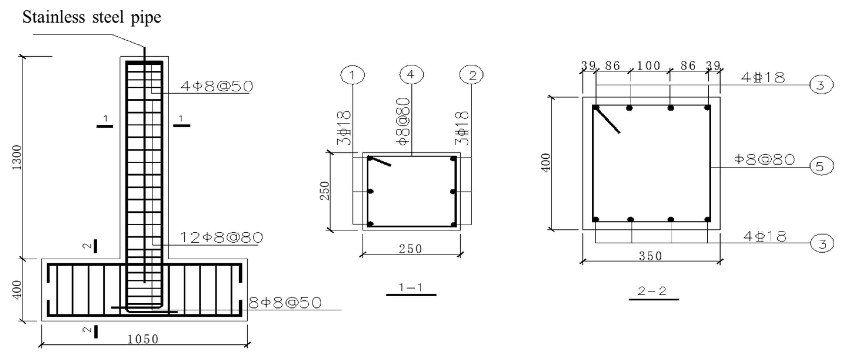
2.1. Specimen Design

Four reinforced concrete columns were designed and fabricated with the corrosion rates set to be 0 and 8%, respectively, in the test. The corrosion process was applied to the reinforcing steel. The corrosion rate determined by the mass loss. The concrete strength grade was C40 with the slump of 16 ± 2 cm. The thickness of the net protective layer was set as 30 mm. Moreover, commercial concrete was applied in present research and the strength grade was C30. The water-to-binder ratio of concrete in all tested specimens was 0.48, and the mixed proportions by weight of cement, sand, coarse aggregates, fly ash, ground granulated basalt furnace slag and superplasticizer were 210, 719, 1112, 70, 70 and 4.18 kg/m3, respectively. Three 16 mm diameter grade III steel (HRB400) longitudinal bars were arranged on each side with symmetrical reinforcement. The stirrups were made of grade I steel (HPB235) with the diameter and spacing of 8 mm and 80 mm, respectively. The stirrups at both ends of the specimen were properly densified with the spacing of 50 mm. The geometric size of specimens and the reinforcement form are shown in Figure 1.
The reinforced concrete columns were strengthened with basalt fiber sheets. The specimens were numbered Z1, Z2, Z3 and Z4, respectively. The specific structural parameters are shown in Table 1.

2.2. Specimen Corrosion Scheme and Control

The wet electrification method was adopted to accelerate corrosion. By putting each specimen into the corresponding corrosion test tank, the corrosion was carried out with a constant voltage and current source. The specific steps are as follows:
(1)
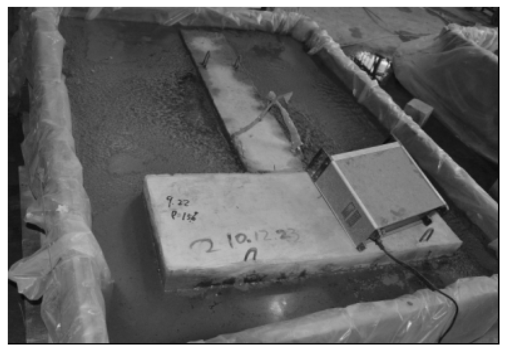
At first, the corrosion test tank were built. After that, specimens were placed into the tank and the water was injected. Then the salt was added to make a 5% NaCl solution. The corrosion rate refers to the mass loss rate. In order to improve the speed of reinforcement corrosion, the high concentrations of NaCl solution were adopted. If water leakage was found, it would be remedied in time.
(2)
The specimens were immersed in the tank for seven days to let the chloride ion enter the concrete and then started energizing. The positive pole of the constant voltage and current source was connected with the hook welded on the specimen. The negative electrode was connected with the stainless-steel tube through a wire, while the stainless-steel tube was put into NaCl solution to act as the cathode. The accelerated corrosion test of the specimen is shown in Figure 2.

2.3. Reinforcement Construction of Reinforced Concrete Column

The reinforcement construction steps of reinforced concrete columns refer to the “Technical Specification for Strengthening Concrete Structure with Carbon Fiber Reinforced Polymer Laminate”. Before reinforcement, the rust on the surface of the corroded concrete column was polished clean. The construction site is shown in Figure 3. Before bonding the FRP sheets, several preparations needed to be finished. Firstly, the crushed concrete and the dust on the surface of the specimens was removed and cleaned up. Secondly, the cracks of the concrete were rehabilitated by the epoxy cement mortar and the rehabilitated specimens needed to be cured for at least one day. When the epoxy cement mortar was hardened, surfaces of the specimens were polished smooth. Subsequently, utilizing the mixed epoxy resins to bond the BFRP sheets and the coatings brushed on the BFRP surface were periodically inspected. The fiber sheets wrapped the reinforced concrete column along the longitudinal fiber direction. At last, additional concentration was taken to guarantee the effectiveness of the coatings, while the epoxy resins needed to be carefully cared for over several days, as shown in Figure 3.

2.4. Material Properties

The measured compressive strength of the concrete standard cube was 40.34 N/mm2. Before the longitudinal bar was corroded, its yield strength and ultimate strength were 440 N/mm2 and 640 N/mm2, respectively. A balance with an accuracy of 0.1 g was used to weigh the longitudinal bars to obtain the weight per unit length of 1.58 g/mm. After the test of the corroded specimen was completed, the main bars, away from the failure section of the damaged specimen, were removed. The main bars were derusted with steel brushes to study the mechanical properties in order to obtain the nominal yield and ultimate strength, as shown in Table 2. The high-performance unidirectional basalt fiber sheet was used and the fiber-bonding impregnation adhesive TLS-503 was selected as the binder. The mechanical properties of the basalt fiber sheet are shown in Table 3. The primer and adhesive used in the reinforcement process were tested by the National Chemical Building Materials Testing Center (Construction Engineering Testing Department). The measured results of colloidal properties and bonding properties are shown in Table 4.

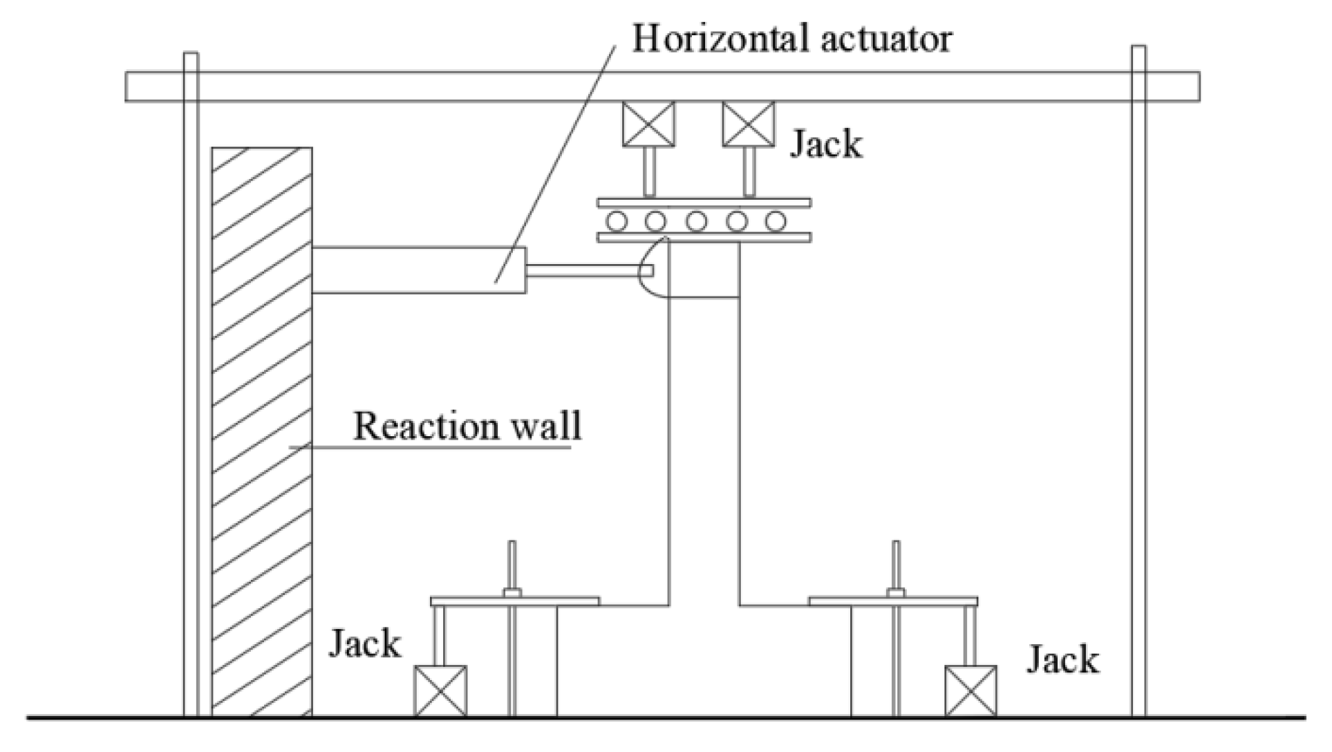
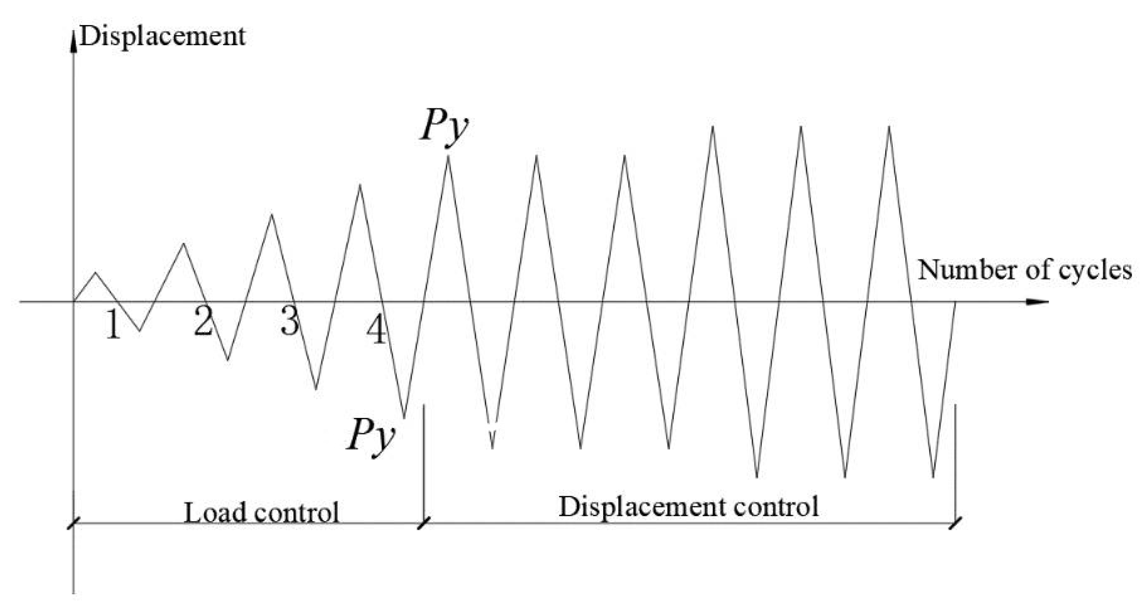
2.5. Test Setup and Loading Method

The load-displacement mixed control loading was adopted in the test, and the loading device is shown in Figure 4. The tested specimens were constructed with a 1/2-scale and tested under the cyclic loading by the Chinese Standard GB 50010–2015 [19]. Dimensions and reinforcements of all tested specimens were identical, as depicted in Figure 4. The vertical load of the specimen was applied through the reaction frame on the test bench. Two 25-ton hydraulic jacks were installed on the reaction frame and placed upside down. Two steel plates with the thickness of 35 mm that clamp the rollers were placed below the jack. The horizontal repeated load was applied by a 500 kN hydraulic actuator (travel of ±150 mm), as shown in Figure 5.
The axial compression ratio was set as 0.2. The vertical load was applied first and then the horizontal repeated load was applied after the vertical load being stable. Before the test, it was determined that the preload repeated load test should be carried out twice and the preload value should not exceed 30% of the calculated value of the cracking load. Before reaching the yield load, the horizontal load control was used first and the cycle was staged with the load of 10 kN in each stage. After reaching the yield load, the cyclic loading was controlled according to the vertex displacement of the column in multiple increments of 4 mm and each stage was cycled three times. The loading procedure is shown in Figure 6.

3. Test Results and Analysis
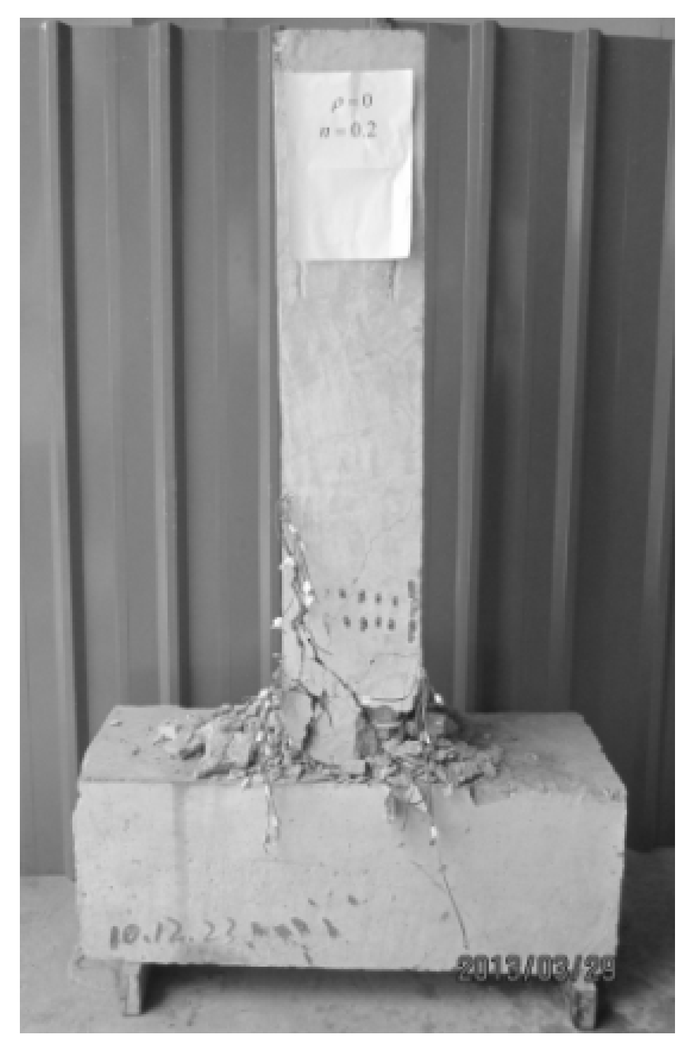
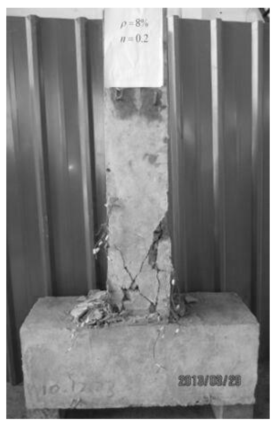
3.1. Failure Mode

When the load of intact specimen Z1 reached 40 kN, 50 kN and 60 kN, the first three bending transverse cracks would appear at the root, 25 cm and 50 cm from the root in turn. When the load was 80 kN, the bending shear oblique crack appeared at 35 cm away from the root and developed along the bending crack. With the increase of the shear force, the bending shear cracks in the parallel plane of the column root continued to develop, penetrate and finally staggered into a network. After the specimen reached the ultimate load, the concrete near the root would be crushed and peeled off in the vertical shear plane, resulting in the decrease of bearing capacity. The plastic hinge was formed at the bottom of the column and the specimen was damaged. With the increase of loading cycles, the horizontal cracks gradually appeared and continued to widen. The cracks were mainly distributed in the height range of about 350 mm to 500 mm from the column root. The horizontal cracks gradually developed obliquely until the forward and reverse cracks were connected. Two or three cracks at the root developed into main cracks. The core concrete was divided into several pieces, which were crushed and destroyed, as shown in Figure 7.
For the intact specimen Z1, the original longitudinal cracks continued to develop under horizontal cyclic loads. The failure process was similar to that of the intact specimen, while the bending transverse crack and bending shear oblique crack appeared when the load reached 30 kN and 60 kN, respectively. Due to the corrosion of steel bars, the bonding performance between the steel bar and the concrete was degraded. When the damage occurred, a large area of protective layer fell off. The longitudinal bar was exposed with the yield of compressed steel bars, as shown in Figure 8. Short vertical cracks appeared only when the specimen was close to the failure load.
For the specimens reinforced with basalt fibers, since the specimens were wrapped, the development of cracks could not be observed during the loading process. However, with the continuous application of horizontal repeated loads, the sound of crackling was constantly heard in the basalt fibers. It can be seen from the last few cycles before the end of the test that the basalt fiber sheet near the root of the column bulged, indicating that the concrete was crushed. However, the concrete was still well wrapped in basalt fiber sheet, as shown in Figure 9 and Figure 10, which means that the basalt fiber can play a useful role in restraining concrete. The corrosion rate of specimen Z3 was 8% and the specimen Z3 was reinforced with one layer of fiber sheet. A slight sound of cracking could be heard when the lateral load was 50 kN, which could be attributed to the breaking of hardened resins. As the test proceeded, the sounds were loud and continuous. However, no evident cracks of the concrete at the surface were observed in the first stage. In the displacement control stage, BFRP sheets fractured at the corners and bulged at the core area when the displacement was 32 and 36 mm, respectively. Due to the crushing of concrete at the core area, the BFRP sheets were entirely bulged and delaminated from the surface when the displacement was 44 mm, as well as the load-bearing capacity decreasing. The test was terminated when the displacement was 66 mm, and the shearing failure mode can be found in Figure 9.
The corrosion rate of specimen Z4 reinforced with two layers of fiber sheet was 8%. A slight sound of cracking could be heard when the lateral load was 60 kN, which could be attributed to the breaking of hardened resins. As the test proceeded, the sounds were loud and continuous. However, no evident cracks of the concrete at the surface were observed in the first stage. In the displacement control stage, BFRP sheets fractured at the corners and bulged at the core area when the displacement was 36 and 40 mm, respectively. Due to the crushing of concrete at the core area, the BFRP sheets were entirely bulged and delaminated from the surface when the displacement was 48 mm, as well as the load-bearing capacity decreasing. The test was terminated when the displacement was 72 mm, and the shearing failure mode can be found in Figure 10.

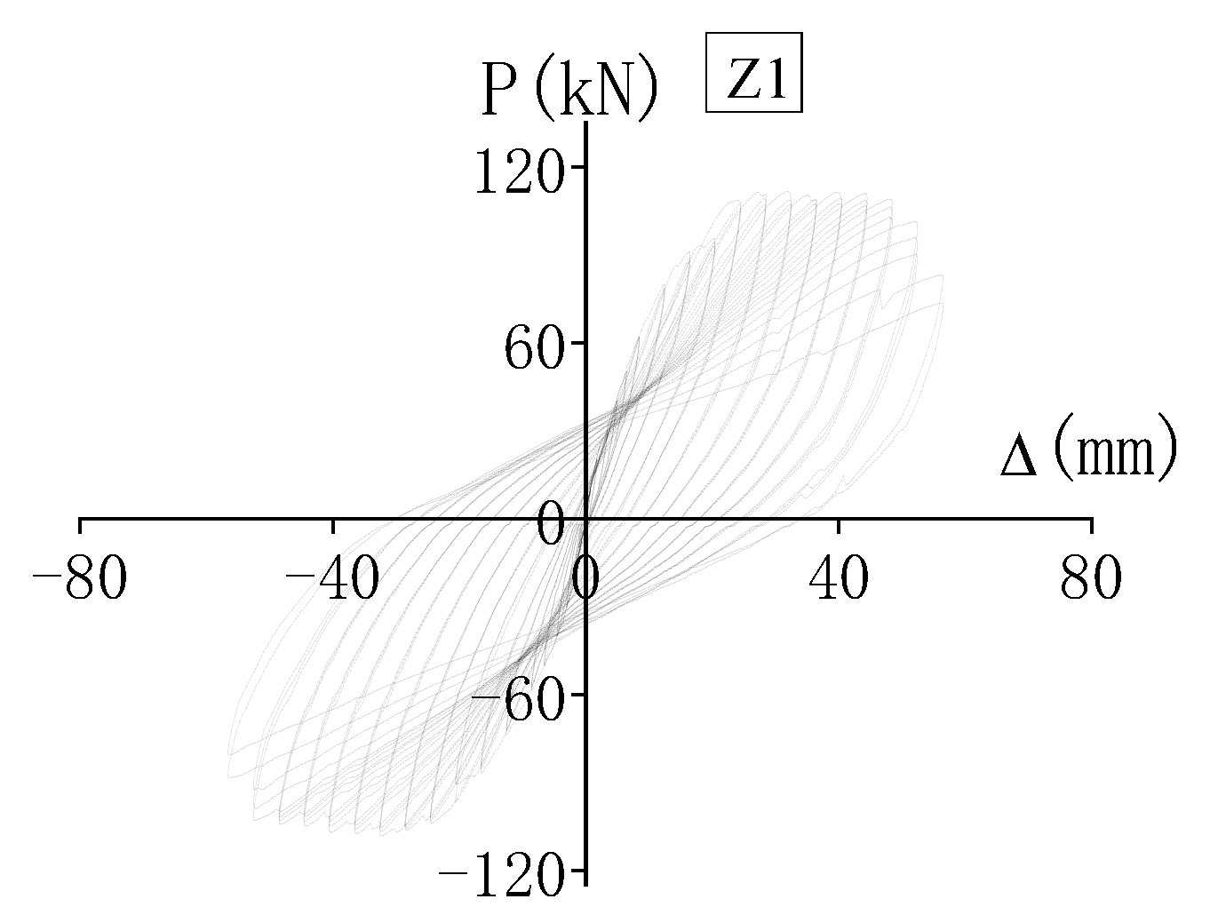
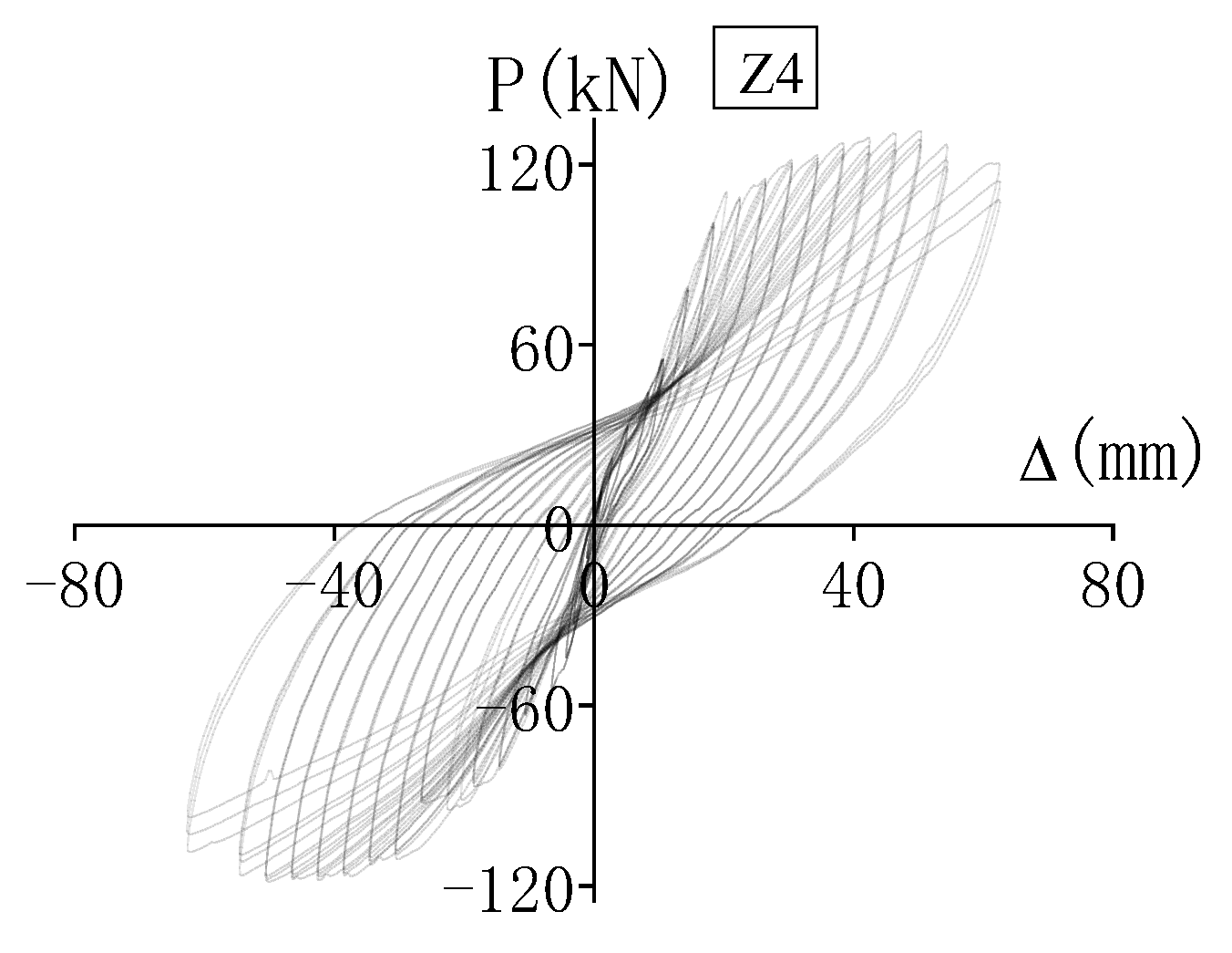
3.2. Hysteretic Performance
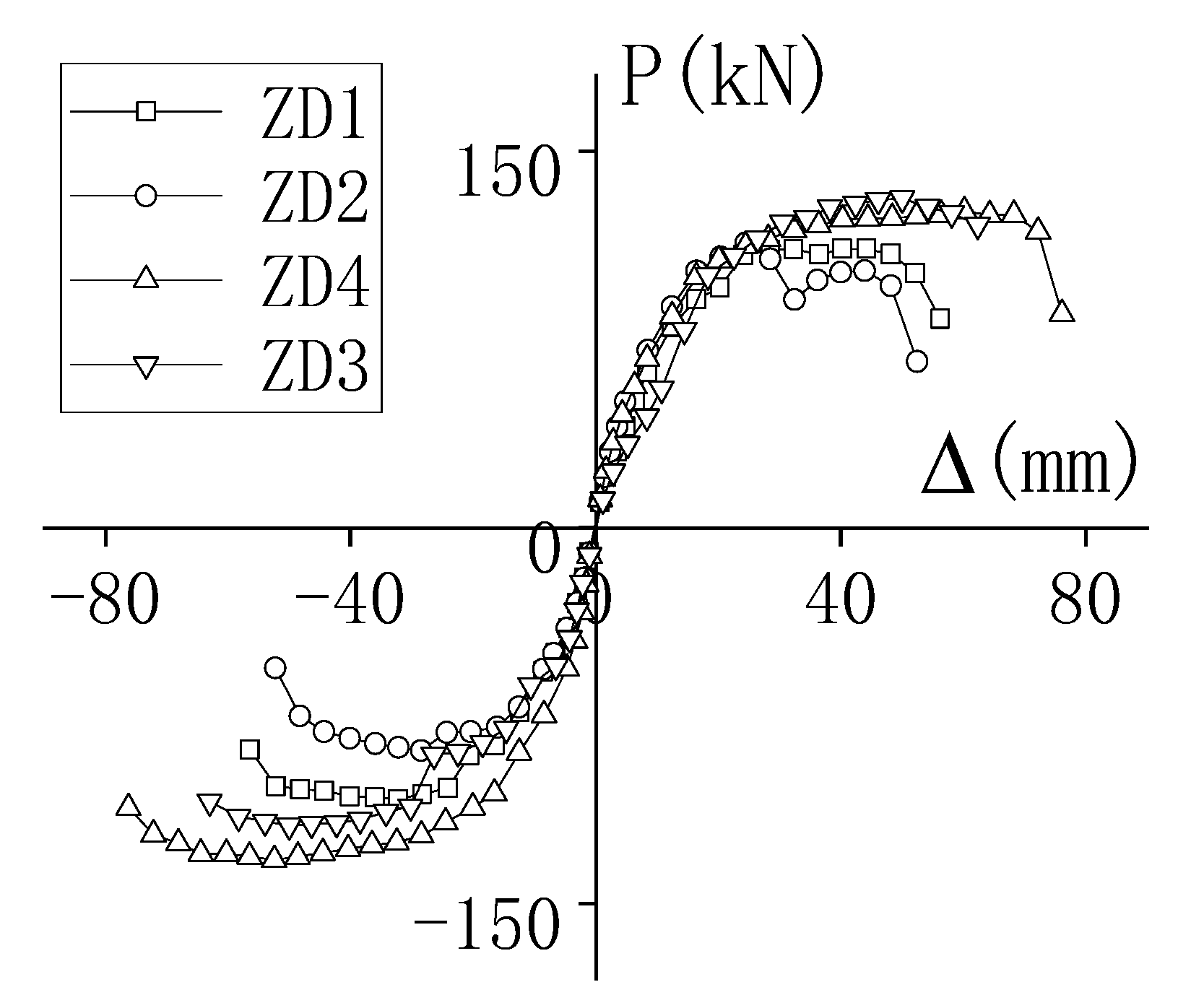
Figure 11, Figure 12, Figure 13 and Figure 14 are the load-displacement hysteresis curves of specimens. It can be seen that the hysteresis curve was basically a straight line without hysteresis loop under small loads. The displacement at the top of column was small and the specimen was in the elastic stage. Before the specimen yielded, the concrete underwent plastic deformation, but the overall deformation was small. The slope of the loading curve changed slightly and there was a small amount of residual deformation after the component was unloaded.
After the specimen yielded, the displacement-controlled loading began. The bearing capacity would continue to increase with a slow growth rate. In addition, it was found that before the load reached the limit, the latter-stage load curve basically passed through the maximum point of the load-displacement in the former-stage load curve. Comparing the loading curves of all stages, the slope of the latter curve was smaller than that of the former curve, indicating that the stiffness of the specimen was degraded under repeated loading.
When the specimen was unloaded, the initial unloading curve was relatively steep and the recovered deformation was very small. The slope of the unloading curve decreased with the increase of unloading times, indicating that the unloading stiffness was degraded.
Figure 11 and Figure 12 are the hysteresis curves of the corroded and intact specimens under the same axial compression ratio. It can be seen that the hysteresis curve of the intact specimen is much fuller than that of the corroded specimen, and the hysteresis loop area is obviously larger, indicating that the energy-dissipation capacity and ductility of specimens decreases after being corroded. The hysteresis curve of the intact specimen Z1 is basically symmetrical, while the curve of the corroded but unreinforced specimen Z2 is asymmetric due to the serious and uneven degree of corrosion.
The Figure 12, Figure 13 and Figure 14 are hysteretic curves of the corroded but unreinforced specimen Z2; the corroded specimen Z3, reinforced with one layer of fiber sheet; and corroded specimen Z4, reinforced with two layers of fiber sheet under the same axial compression ratio. It can be seen that the hysteretic curves of Z3 and Z4 are much fuller than that of Z2, and the hysteretic loop area is obviously larger. The results show that the bearing capacity, energy-dissipation capacity and ductility of specimens is greatly improved after being reinforced with basalt fiber sheet.

3.3. Backbone Curve

The envelope curve formed by the peak point in the first cycle at each loading stage of the load-displacement curve shall be taken as the backbone curve of concrete specimen. The strength, stiffness and ductility of the specimen can be more clearly reflected in the backbone curve. The backbone curves of each specimen were plotted in Figure 15.
As shown in Figure 15, the bearing capacity and ductility of corroded specimen Z2 were significantly lower than those of intact specimen Z1. The corroded and strengthened specimens Z3 and Z4 have higher bearing capacity and ductility than the intact specimen after reinforcement. A similar conclusion can also be found in [20,21].

3.4. Ductility and Bearing Capacity

Pu is the ultimate load of the specimen, and the failure load was taken as 0.85Pu. Δu is the ultimate displacement of the specimen; Δy is the yield displacement; u = Δu/Δy, is the displacement ductility ratio. The values of load and displacement at each stage were listed in Table 5.
The results of specimens Z1 and Z2 were compared as shown in Table 5. Compared with the intact specimen Z1, the bearing capacity and ductility of Z2 with a corrosion rate of 8% decreased by 10.1% and 14.8%, respectively. Therefore, the steel bars with severe corrosion (>8%) will lead to a significant decrease in the bearing capacity and ductility of the specimens. The ductility of the corroded specimen decreased more obviously than the bearing capacity.
The bearing capacity of the strengthened specimens Z3 and Z4 with a corrosion rate of 8% was increased by 4.1% and 13.99%, respectively, and the ductility was increased by 6.58% and 10.95%, respectively, compared with the intact specimen Z1. The bearing capacity of the strengthened specimens Z3 and Z4 with corrosion rate of 8% was increased by 16.1% and 20.6%, respectively, and the ductility was increased by 24.14% and 30.27%, respectively, compared with the specimen Z2 with a corrosion rate of 8%. It can be seen that the bearing capacity and ductility of the specimen was greatly improved due to the wrapping of basalt fiber sheet. With the increase of reinforcement layers, the restraint effect of basalt fiber sheet on the specimen also increased, and the improvement effect on the bearing capacity and ductility of reinforced specimens was also more obvious.
This indicates that utilizing a BFRP sheet can rehabilitate the ductility and bearing capacity of corroded to the level of the uncorroded specimen, and similar results can also be found in [22,23].

4. Conclusions

By carrying out low-cycle repeated tests of four reinforced concrete columns, the failure process and formation of concrete columns under working conditions of no corrosion, corrosion and corrosion reinforcement were described. The effect of changes in parameters, such as the corrosion rate and the reinforcement layers of basalt fiber on the seismic performance of reinforced concrete columns, were compared and analyzed. The conclusions are as follows:
(1)
The basalt fiber sheet bulged under horizontal repeated loads, indicating the crush of concrete. However, the concrete was still well wrapped in the basalt fiber sheet, which plays a good role in restraining the concrete.
(2)
The hysteresis curve of the intact specimen is much fuller than the corroded specimens and the hysteresis loop area is obviously larger, indicating that the energy-dissipation capacity and ductility of specimens is reduced after corrosion. The hysteretic curve of the specimen strengthened with basalt fiber sheet is much fuller than that of the corroded specimen with a larger hysteretic loop area, indicating that the bearing capacity, energy-dissipation capacity and ductility is greatly improved when reinforced with basalt fiber sheet.
(3)
The bearing capacity and ductility of the corroded specimens under repeated horizontal loads were significantly weakened compared with the intact specimens, while the bearing capacity and ductility of the corroded and reinforced specimen all exceeded those of the intact specimen.
(4)
The restraint effect of basalt fiber sheet on the specimen increases with the reinforcement layers. The more reinforced layers of basalt fiber sheet, the more obvious the ductility of the reinforced specimens is improved.

Author Contributions

Conceptualization, methodology, formal analysis and investigation, writing—original draft preparation, J.Y.; writing—review and editing, resources, supervision, validation, D.S. All authors have read and agreed to the published version of the manuscript.

Funding

The financial support of the National Key R&D Program of China (Grant No. 2018YFC0705800) and the National Natural Science Foundation of China (Grant No. 51879092) are gratefully acknowledged. This work is also sponsored by Enterprise Practice Training of Young Teacher Project of Vocational College of Jiangsu Province of China.

Institutional Review Board Statement

Not applicable.

Informed Consent Statement

Not applicable.

Data Availability Statement

Not applicable.

Conflicts of Interest

The authors declare no conflict of interest.

References

  1. Choe, G.; Shinohara, Y.; Kim, G.; Lee, S.; Lee, E.; Nam, J. Concrete corrosion cracking and transverse bar strain behavior in a reinforced concrete column under simulated marine conditions. Appl. Sci. 2020, 10, 1794. [Google Scholar] [CrossRef] [Green Version]
  2. Ou, Y.C.; Nguyen, N.D. Influences of location of reinforcement corrosion on seismic performance of corroded reinforced concrete beams. Eng. Struct. 2016, 126, 210–223. [Google Scholar] [CrossRef]
  3. Zheng, A.H.; Li, S.; Zhang, D.F.; Yan, Y.H. Shear strengthening of RC beams with corrosion-damaged stirrups using FRP grid-reinforced ECC matrix composites. Compos. Struct. 2021, 272, 114229. [Google Scholar] [CrossRef]
  4. Firouzi, A.; Abdolhosseini, M.; Ayazian, R. Service life prediction of corrosion-affected reinforced concrete columns based on time-dependent reliability analysis. Eng. Fail. Anal. 2020, 117, 104944. [Google Scholar] [CrossRef]
  5. Shi, Q.X.; Niu, D.T.; Yan, G.Y. Experimental research on hysteretic characteristics of corroded RC members with fiexural and compressive axial loads under repeated horizontal loading. Earthq. Eng. Eng. Vib. 2000, 20, 44–50. [Google Scholar]
  6. Yan, G.Y.; Sun, B.N.; Wang, Z.J.; Niu, D.T. Experimental research on seismic behavior of the corroded RC members with bending and compression loads. J. Build. Struct. 2003, 33, 16–18. [Google Scholar]
  7. Niu, D.T.; Chen, X.X.; Wang, X.M. Experimental study on seismic performance of corroded reinforced concrete members with flexure and compression. J. Build. Struct. 2004, 34, 36–38. [Google Scholar]
  8. Chen, X.X.; Niu, D.T.; Wang, X.M. The force-restoring model of corroded reinforced concrete members with flexure and compression. J. Xi’an Univ. Archit. Technol. (Nat. Sci. Ed.) 2005, 37, 155–159. [Google Scholar]
  9. Gong, J.X.; Zhong, W.Q.; Zhao, G.F. Experimental study on low-cycle behavior of corroded reinforced concrete member under eccentric compression. J. Build. Struct. 2004, 25, 92–104. [Google Scholar]
  10. Gong, J.X.; Li, J.B.; Zhao, G.F. Restoring force model of corroded reinforced concrete elements. China Civil. Eng. J. 2005, 8, 38–101. [Google Scholar]
  11. Jiang, L.J.; Yuan, Y.S. Experimental study on stiffness deterioration of corroded reinforced concrete column for axial load and moment under cyclic loading. J. Concr. 2011, 5, 3–5. [Google Scholar]
  12. Jiang, L.J.; Yuan, Y.S. Restoring force model of corroded reinforced concrete column for axial load and moment. J. Concr. 2011, 6, 29–32. [Google Scholar]
  13. Li, J.B. Study on Seismic Strengthening of Corroded Reinforced Concrete Columns. Ph.D. Thesis, Dalian University of Technology, Dalian, China, 2009. (In Chinese). [Google Scholar]
  14. Li, J.B.; Gong, J.X. Influences of rebar corrosion on seismic behavior of circular RC columns. China J. Highw. Transp. 2008, 21, 55–60. [Google Scholar]
  15. Li, J.B.; Gong, J.X. Experimental research on ductile behavior of corroded reinforced concrete column confined with CFRP. J. Dalian Univ. Technol. 2010, 50, 220–227. [Google Scholar]
  16. Li, J.B.; Gong, J.X.; Wang, L.H. Experimental study on seismic behavior of corroded reinforced concrete columns strengthened with concrete jacket and CFRP. China Civil. Eng. J. 2009, 42, 17–26. [Google Scholar]
  17. Gong, J.X.; Zhang, Y.Q.; Li, J.B. Research on seismic behavior of corroded and reinforced concrete specimens. Constr. Technol. 2011, 40, 74–80. [Google Scholar]
  18. Gong, J.X.; Li, J.B.; Cheng, L. Seismic behavior of strengthened corrosion-damaged circular reinforced concrete columns. China J. Highw. Transp. 2010, 23, 41–48. [Google Scholar]
  19. GB 50010-2015; Chinese Standard, Code for Design of Concrete Structures. Ministry of Housing and Urban-Rural Development of the People’s Republic of China: Beijing, China, 2010. (In Chinese)
  20. Shen, D.J.; Yang, Q.; Huang, C.B.; Cui, Z.H.; Zhang, J.Y. Tests on seismic performance of corroded reinforced concrete shear walls repaired with basalt fiber-reinforced polymers. Constr. Build. Mater. 2019, 209, 508–521. [Google Scholar] [CrossRef]
  21. Jiang, S.F.; Zeng, X.X.; Shen, S.; Xu, X.C. Experimental studies on the seismic behavior of earthquake-damaged circular bridge columns repaired by using combination of near-surface-mounted BFRP bars with external BFRP sheets jacketing. Eng. Struct. 2016, 106, 317–331. [Google Scholar] [CrossRef]
  22. Ma, G.; Chen, X.H.S.; Yan, L.B.; Hwang, H.J. Effect of pre-damage on compressive properties of circular RC columns repaired with BFRP composites: Testing and modeling. Compos. Struct. 2020, 247, 112483. [Google Scholar] [CrossRef]
  23. Liu, X.F.; Li, Y. Experimental study of seismic behavior of partially corrosion-damaged reinforced concrete columns strengthened with FRP composites with large deformability. Constr. Build. Mater. 2018, 191, 1071–1081. [Google Scholar] [CrossRef]
Figure 1. Geometric size of column and arrangement of bars.
Applsci 12 05611 g001
Figure 2. The accelerated corrosion of specimens.
Applsci 12 05611 g002
Figure 3. (a) A roll of fiber sheets. (b) Shape of the basalt fiber sheet. (c) bonding between BFRP and corroded concrete column.
Applsci 12 05611 g003
Figure 4. Scheme of test set-up.
Applsci 12 05611 g004
Figure 5. Photo of test set-up.
Applsci 12 05611 g005
Figure 6. Loading procedure.
Applsci 12 05611 g006
Figure 7. Z1 (ρ = 0).
Applsci 12 05611 g007
Figure 8. Z2 (ρ = 8%).
Applsci 12 05611 g008
Figure 9. Z3 (ρ = 8%, one layer).
Applsci 12 05611 g009
Figure 10. Z4 (ρ = 8%, two layers).
Applsci 12 05611 g010
Figure 11. Hysteretic curve Z1 (ρ = 0).
Applsci 12 05611 g011
Figure 12. Hysteretic curve Z2 (ρ = 8%).
Applsci 12 05611 g012
Figure 13. Hysteretic curve Z3 (ρ = 8%, one layer).
Applsci 12 05611 g013
Figure 14. Hysteretic curve Z4 (ρ = 8%, two layers).
Applsci 12 05611 g014
Figure 15. Backbone curve of specimens.
Applsci 12 05611 g015
Table 1. Main parameters of hysteretic specimens.
SpecimensDesigned Corrosion RateAxial Compression RatioReinforcement Form
Z100.2not reinforced with FRP
Z28%0.2not reinforced with FRP
Z38%0.2jacketed with FRP (one layer)
Z48%0.2jacketed with FRP (two layers)
Table 2. Material properties of main reinforcement.
SpecimensActual Corrosion RateNominal Yield Strength (N/mm2)Nominal Ultimate Strength
(N/mm2)
Z10440640
Z28.4%399587
Z39.1%376547
Z47.6%415592
Table 3. Technical indexes of basalt fiber sheet.
NumberTest ItemsTest Results
1Tensile strength (MPa)2303
2Elastic modulus (MPa)1.05 × 10⁵
3Elongation (%)2.18
Table 4. Test results of colloid and bonding properties.
NumberTest ItemsTest ResultsTest Results
Class AClass B
1Colloidal propertiesTensile strength (MPa)≥40≥3045.79
Elastic modulus (MPa)≥2.5 × 10³≥1.5 × 1032.6 × 103
Elongation (%)≥1.53.47
2Bonding propertiesNormal bonding strength with concrete (MPa)≥2.5 (C30 Concrete failure)5.87
Table 5. Characteristic loads and ductility of specimens.
SpecimensPu (kN)Δy (mm)Δu (mm)u0.85Pu (kN)
Z1109.5814.4354.273.7693.14
Z298.512.5146.223.6983.73
Z3114.0414.5257.843.9896.93
Z4124.915.0960.213.99106.17
Publisher’s Note: MDPI stays neutral with regard to jurisdictional claims in published maps and institutional affiliations.

