Article

Structural Analysis and Form-Finding of Triaxial Elastic Timber Gridshells Considering Interlayer Slips: Numerical Modelling and Full-Scale Test

by
Antonio José Lara-Bocanegra
1,*,
Almudena Majano-Majano
1,
Juan Ortiz
2 and
Manuel Guaita
2
1
Department of Building Structures and Physics, School of Architecture, Universidad Politécnica de Madrid, avda. Juan de Herrera 4, 28040 Madrid, Spain
2
Department of Agroforestry Engineering, University of Santiago de Compostela, calle Benigno Ledo, 27002 Lugo, Spain
*
Author to whom correspondence should be addressed.
Appl. Sci. 2022, 12(11), 5335; https://doi.org/10.3390/app12115335
Submission received: 16 April 2022 / Revised: 23 May 2022 / Accepted: 23 May 2022 / Published: 25 May 2022
(This article belongs to the Special Issue Gridshells: From Materials to Structures)

Abstract

:
Elastic timber gridshells are lightweight structures whose stiffness is highly dependent on multiple factors, such as boundary conditions and the semi-rigidity and eccentricity of the joints. Their structural analysis requires calibrated numerical models that incorporate all aspects influencing stiffness. Unfortunately, very little research on experimentally verified numerical models can be found. This paper focuses on the structural behaviour of a novel concept of triaxial elastic long-gridshells supported only on their short sides, called by the authors TEL-gridshells. First, the most relevant details of the construction process and the load test of a full-scale laboratory prototype are presented. Then, two finite element models for structural analysis and form-finding are proposed. Both are based on the modelling of the joints using a series of aligned couplings that allow the integration of the actual joint eccentricity and the interlayer slip by means of springs in all shear planes. The first model replicates the geometry of the prototype built from experimental measurements, focusing on stiffness calibration. The results of the load test are used to verify the proposed model and to analyse the most influential aspects on the stiffness of the structure. The second is a form-finding model that reproduces the construction process of the laboratory prototype, focusing on the residual stresses generated during the deformation process of the structural elements. From the numerical results, the structural behaviour of the prototype is discussed and some of the main aspects to be considered in the design and structural analysis of TEL-gridshells are established.

1. Introduction

Elastic timber gridshells, also known as strained timber gridshells [1,2] or active bending gridshells [3], are a highly efficient and architecturally expressive structural solution of great interest for application in lightweight roofs of medium and large spans. They are built from initially straight timber laths, of small cross-section and great length, which are elastically deformed until they reach the final shape, giving rise to a structural grid of continuous elements.
Traditional elastic gridshells can be classified into two groups according to the curving process of the laths and the multilayer system used.
The first, developed by Prof. Frei Otto and colleagues at the Institut für leichte Flächentragwerke (Institute for Lightweight Structures) in Stuttgart, Germany, is based on the premise that a flat quadrangular grid of continuous timber laths connected by hinged joints that allow rotation around an axis perpendicular to the plane of the grid, can be transformed into a doubly curved surface. The transformation is possible owing to the elastic deformation of the laths and the lack of in-plane shear stiffness of the grid during the curving process [4]. Spectacular structures have been realised following this procedure, such as antifunicular surfaces as the Mannheim Multihalle gridshell (1975), with a maximum span of 60 m [5], or undulating forms as the Weald & Downland Living Museum gridshell (2002) [6] and the Savill Garden gridshell (2006) [7], with 15 and 25 m span, respectively. In all these structures, two layers of laths have been necessary to provide the grid with the required out-of-plane bending stiffness. The connection between the different layers is always made after the curving process. This results in a composite profile with high inertia, while maintaining the minimum radius of curvature of each lath. The connection system between the different timber layers is solved by means of mechanical fasteners that produce semi-rigid joints. This connection can be made in different ways: at the nodes using bolts, as in the Mannheim Multihalle [5] (Figure 1a); at the nodes and members, as in the Weald & Downland Living Museum gridshell [6] (Figure 1b), where shear blocks were used at the members and a patented steel connection at the nodes; or exclusively at the members by means of timber shear blocks fastened with screws to the laths, as in the Savill Garden gridshell [7] (Figure 1c).
The second group of gridshells, developed at École Polytechnique Fédérale de Lausanne (EPFL) in Switzerland by the engineer J. Natterer, is based on the idea of constructing grids formed by two directions of curved elements generated by mechanical lamination. This is done by nailing and/or screwing multiple layers of overlapping laths together, creating a solid cross-section of ribs with high inertia (Figure 1d), so structures built with this technique are called ribbed shells [8]. Unlike F. Otto’s concept, initially the laths do not have to be part of a grid and can therefore be individually curved [9]. This allows greater freedom in both surface geometry and mesh geometry, the latter being able to be irregular. Although the system allows any surface to be constructed and any grid layout to be adopted, J. Natterer used preferably canonical surfaces and geodesic paths for the laths, as these do not involve strong axis bending during the curving process. Impressive structures have been built following this technique, such as the cylindrical 22 m spanning Kleinmachnow Sporthalle in Berlin (1997); several spherical shells, such as the 25 m side Polydôme EPFL (1991); or the Expodach in Hannover (1999) [10].
Recent research carried out by the authors has combined features of both procedures to develop an innovative concept of long gridshells supported only on their short sides that offers new and interesting architectural applications. The grid layout consists of three directions of bent laths to provide out-of-plane bending stiffness (Figure 2 left). Two of these, arranged longitudinally, generate a diamond pattern and lay on the supports. The third, in the transverse direction, triangulates the grid and also works as a bracing system. Due to the small radius of curvature in this transverse direction, the laths must have very small thicknesses, so mechanical lamination of thin pieces is used to achieve the required thickness, similar to that proposed by Natterer.
This concept, referred here as triaxial elastic long-gridshells (hereafter TEL-gridshells), has been successfully implemented in the construction of a first permanent 24 m long roof, called the PEMADE gridshell (Figure 2 right) [11,12,13].
The aim of the present work is to analyse the structural behaviour of TEL-gridshells based on the load test of a full-scale laboratory prototype and numerical analyses using finite element models (FEM). This first involves a review of the main approaches to the development of computational models for structural analysis and form-finding of elastic gridshells, with emphasis on the modelling strategy of the multilayer system and the simplifications adopted. Based on the analysis performed, a new modelling strategy for elastic timber gridshells is proposed, which consists of including all the joints of the structure with the actual eccentricity and slip in them by using couplings and springs. Then, a load test of a full-scale TEL-gridshell lab prototype is presented, including a description of the main structural details and the construction process, which are used as a reference for the development of two FEM models. The first model replicates the geometry of the prototype built from experimental measurements, focusing on the stiffness calibration. The second is a form-finding model that reproduces the construction process of the TEL-gridshell lab prototype, focusing on the residual stresses generated during the deformation process. The results of the load test are used to verify the proposed model and to analyse the most influential features on the stiffness of the structure. From the numerical results, the structural behaviour of the prototype is discussed, concluding with some of the key aspects to consider in the design and structural analysis of TEL-gridshells.

2. Overview of Structural Analysis and Form-Finding of Elastic Timber Gridshells

Structural analysis is one of the main topics in the design of elastic timber gridshells and remains an open research challenge. The existence of significant residual stresses due to the construction process, of eccentricities in the nodal joints caused by the multilayer configuration and of slip in the connection elements, typical of mechanical joints in timber, represent issues of considerable complexity in terms of computational modelling. This is coupled with a marked non-linear response of the structure due to the high slenderness and other phenomena such as a possible non-linear behaviour of the joints, and the rheological properties of the material both in terms of deformation amplification (creep) and stress reduction due to the forming process (stress relaxation). Incorporating all these aspects into a single model can be counterproductive, as too much complexity of the model requires high development cost and usually implies a decrease in operability. For this reason, engineers and researchers have often opted to develop simplified models which, to a greater or lesser extent, omit some of the above-mentioned aspects.
In addition to these conditions intrinsic to elastic timber gridshells, a crucial aspect in their design is to ensure that the constructed structure will maintain the designed geometry after all auxiliary elements have been removed from the construction site. This can be guaranteed for any shape and boundary conditions if multilayer and bracing systems with adequate stiffness are used, which is the usual solution (and condition) for elastic timber gridshells in building construction. In single-layer gridshells, it is also necessary to limit the movements of the entire perimeter. Otherwise, when the auxiliary elements are removed, the structure will move in search of the equilibrium position of minimum strain energy, which will generally not coincide with the projected shape. In the latter case, the design of the structure cannot be done by geometrical methods, and it is necessary to resort to form-finding strategies. In short, two approaches are possible: (1) modelling the final geometry; or (2) modelling the deformation process by means of form-finding methods, which allows residual stresses to be obtained.

2.1. Numerical Modelling for Structural Analysis from the Final Geometry

For elastic timber gridshells used in building construction, a very practical approach is to model the geometry to be built by performing a non-linear geometric analysis at large deformations (usually solved with methods based on Newton-Rapson iteration scheme). The model must take into account the slip at the joints of the multilayer system. One possible strategy is to replace the slipping multilayer system with simple elements of equivalent stiffness. This approach was applied in the analysis of the Mannheim Multihalle gridshell. In this case, the multilayer structure was simplified into simple elements of reduced second moment of area with respect to the full composite member, assuming linear elastic behaviour of the joints [5]. A similar strategy was proposed for the analysis of ribbed shells [8,14], which can be adequately modelled by applying the shear analogy method developed for layered timber beams [15]. This method transforms each multilayer timber rib into a model of two beams connected by inextensible bars with equivalent bending and shear stiffness, considering also a linear behaviour of the connections. In both cases, eccentricities between layers were not considered.
Subsequent work included eccentricity between the layers of elastic gridshells through small rigid couplings. The use of couplings also makes it possible to incorporate the complete multilayer system without resorting to simplified elements of equivalent stiffness. One possible solution is to adjust the bending stiffness of the coupling so that it produces the same deformation as the expected slip at the joints [16]. This solution only assumes a linear behaviour of the joints. Numerical investigations carried out on the buckling analysis of elastic gridshells in composite materials [17] and timber [18] have shown the importance of considering eccentricities in the model of single-layer elastic gridshells, as they can significantly reduce the stiffness of the structure and consequently the critical buckling load. However, in multilayer gridshells, the effect of eccentricity is much less relevant [18].
Numerous works in the field of simulation of timber composite elements e.g., [19,20] have demonstrated the effectiveness of couplings (or link elements) and springs for modelling the behaviour of multilayer elements joined with mechanical fasteners. In these cases, the couplings are rigid and the slip at the joints is included from the stiffness of the springs. This approach has also been successfully used in the modelling of small-scale elastic timber gridshells [21] and allows easy consideration of linear and non-linear behaviour of the joints.
Obviously, when directly modelling the final geometry, additional considerations on the residual stresses due to the forming process are necessary and depend on the individual case. For multilayer structures made with laths of very small thicknesses and large curvature radii, the stresses may be very small and could be neglected [8]. In structures built with wet timber that bend very slowly (several months), as in the case of the Weald & Downland Living Museum gridshell or the Savill Garden gridshell, the initial stresses dissipate to a large extent. Under these conditions, one approach could be to disregard the curving stresses, but to consider a reduction in the timber bending strength, similar to the standard procedure applied in the sizing of glulam arches [22]. However, in most cases it is necessary to take into account the forces resulting from the construction process, especially bending moments. These can be derived geometrically from a curvature analysis of the grid [8,23] and considered as prestress loads [11] or strains loads [24,25].

2.2. Numerical Modelling for Form-Finding

A very different approach to consider residual stresses is to simulate the gridshell construction process. This approach is also necessary when the final shape of the structure depends on the internal strain forces.
Modelling the forming process involves solving very important geometrical non-linearities due to the large displacements and rotations that take place during the deformation. This problem has been addressed by the scientific community in recent years in the general field of active bending systems (e.g., [26,27]) as well as in the specific field of elastic gridshells, mainly using the dynamic relaxation (DR) method and FEM.
DR solvers with three degrees of freedom (DoF) per vertex have been widely used for the form-finding of single-layer elastic gridshells made of composite materials, with circular cross-sections and no slip at the joints [28,29]. However, these models can not accurately represent the behaviour of rectangular cross-sections which present torsion and bending in the two axes of inertia. The 4 and 6 DoF methods overcome this limitation, but have been applied exclusively to single-layer gridshells, also without slip at the joints [30,31,32,33,34]. A 6 DoF method for the form-finding of multilayer timber gridshells was developed in [35]. It conducted form-finding by initially considering a single layer. Once the final shape was reached, the bending stiffness of the members was modified by attributing a new equivalent bending stiffness, corresponding to that of the considered multilayer system. The new stiffness was assigned according to the Gamma Method included in Eurocode 5 [36] for the analysis of mechanically connected composite beams, which assumes linear behaviour of the connections. This model did not consider the eccentricity of the connections. Subsequent work with a similar approach was carried out by [3].
FEM simulations have also been used for the form-finding of single-layer gridshells with circular and rectangular cross-sections [1,37,38], including the eccentricity between the laths by means of small couplings that allow rotation around the vector perpendicular to the grid surface. Although these models do not include multilayer systems or semi-rigidity in the joints, the great advantage of this method is that it allows a complete mechanical description of the structure, making it possible the simultaneous use of different types of elements (Timoshenko beams, cables, couplings, springs, etc.) and assigning them the actual physical properties, including non-linear behaviour if necessary. In addition, the main FEM software packages have the possibility to activate and deactivate temporary elements at different stages to perform the simulation of the forming process. This has been done by two procedures: the imposition of a displacement field at certain grid nodes, or the use of temporary elastic contraction elements [39]. The latter has the advantage of not requiring knowledge of the intermediate path of the points during the curving process. In addition, the increasing interoperability of parametric design software and FEM allows virtually unlimited modelling capabilities.
As gridshells are structures with high deformability and hyperstability, it is essential that the numerical models are properly calibrated, including the main elements that influence the stiffness of the structure, to correctly estimate the stresses and the global deformability. Unfortunately, very little research can be found that has validated the proposed models with full-scale tests. In single-layer elastic gridshells made of composite materials, some of the research mentioned above has compared structural analysis and form-finding simulations with the experimental results of full-scale prototype tests [37,40]. However, in the case of timber, research in this direction is really scarce (e.g., [8]).

3. TEL-Gridshell Lab Prototype

This section describes the construction process and main structural details of a laboratory prototype of a triaxial elastic long-gridshell supported on its short sides. A load test is also presented in which the displacements of all nodes and midpoints of the members are measured using low-cost photogrammetric techniques. These measurements are complemented by the use of several transducers.

3.1. General Description

A laboratory prototype was built with the TEL-gridshell concept, similar to that of the PEMADE gridshell (see Figure 2). Specifically, it is a barrel-shaped structure with a 6.5 m span supported on two semicircular supports. Its theoretical form is determined geometrically by generating a loft between three semicircular cross-sections, the two at the ends with a radius of 1.45 m and the central one with a radius of 1.60 m, whose centre was vertically displaced 0.10 m with respect to the centres of the other two. The grid was defined by two directions of longitudinal laths with 1.64 m interaxis and a third transverse direction of laths acting as a bracing system (Figure 3).
The cross-sections of the longitudinal and transverse laths were dimensioned to limit the bending stresses due to curving to 55% and 75% of the characteristic bending strength of the timber, respectively. These are very high values but leave sufficient structural reserve for the load test. In a permanent structure, the bending stresses caused by the curving process should be limited to lower ratios considering the corresponding safety coefficients. Clearly, one solution to reduce the stresses due to curving would have been to reduce the cross-sections of the laths, but the priority in this case was to use cross-sections of similar size to those that could be used in a real permanent structure.

3.2. Material

Fifty-three boards of three meters in length of Eucalyptus globulus L. from Galicia, Spain, were used to produce the laths. They were first visually graded according to UNE 54566:2013 [41] and conditioned at 65% relative humidity and 21 °C temperature until equilibrium moisture content was reached. The static modulus of elasticity (Em,0) of the boards was determined from edgewise bending tests under four-point loading according to UNE-EN 408:2011+A1 [42], giving an average value of 17,544 N/mm2 (standard deviation of 3396 N/mm2). The material density (ρmean) was also measured resulting in an average value of 795 kg/m3 (standard deviation of 90 kg/m3). The values obtained are very close to the mean values for the species reported in the Spanish standard UNE 565464:2013 [41] (Em,0 = 18,400 N/mm2 and ρmean = 797 kg/m3).
Subsequently, small knots were removed from the boards to ensure high quality. Finger-joints produced with a 15 mm nominal finger length cutter were performed in accordance with previous research by the authors [43] to obtain high performance laths of approximately 7.5 m in length. The estimated characteristic flatwise bending strength, considering the actual cross-section of the laths, was 63.9 N/mm2 according to previous experimental research by the authors [24]. A 40-mm thick pine laminated veneer lumber (LVL) panel was used to make the gridshell supports.

3.3. Construction Process

A total of 18 finger jointed solid timber laths were planned to a final cross-section of 60 × 25 mm2 and used to build the principal grid of the prototype (Figure 3).
Two levelled beams of GL24h spruce glulam were arranged longitudinally on the floor as a horizontal base. Then, the two semicircular LVL supports of 2.9 m diameter were placed on them. Such semicircular supports were reinforced on both sides with timber pieces of 40 × 220 mm2 cross-section obtained from the same LVL panel. These pieces joined the support points of the gridshell on the semicircular LVL panel, with the support points of the panel on the two level beams. Once the grid was built, it was closed and then unfolded on the semicircular supports. When the final shape was achieved, the third layer of bent laths was arranged in the form of small transverse arches to provide the structure in-plane shear stiffness. Due to the small radius of curvature in this direction, these transverse laths were made as a mechanical laminate of three 60 × 8.3 mm2 pieces using small screws, resulting in a final cross-section of 60 × 25 mm2.

3.4. Joints

All gridshell joints were solved by mechanical fasteners that produced sliding in the shear planes. Three different types of joints can be found: the grid nodal joint (Type 1), consisting of 5 eucalyptus layers (two of 60 × 25 mm2 and three of 60 × 8.3 mm2) connected by a 6 mm diameter screw (Figure 4 left); the gridshell support on the semicircular LVL panels (Type 2), consisting of two 60 × 25 mm2 eucalyptus laths fixed to the panels by means of 8 mm diameter screws (Figure 4 middle); and the joint corresponding to the mechanical lamination of the transverse laths (Type 3), consisting of three 60 × 8.3 mm2 eucalyptus laths joined by 4 mm diameter screws at 60 mm spacing (Figure 4 right).

3.5. Full-Scale Loading Test

A load test was performed on the gridshell. This was carried out one week after the prototype was built to allow for some relaxation of the initial bending stresses due to the construction process. This decrease can be estimated to be 78% according to previous research by the authors [22]. The five central nodes of the lath corresponding to the plane of transverse symmetry of the grid were loaded with a force of 1.04 kN/node. To this end, plastic graduated containers of 50 L capacity were hung in pairs from the corresponding nodes. They were then filled slowly and symmetrically with water to avoid sudden movements (Figure 5).

3.6. Measurement of Displacements

Photogrammetric measurements were taken during the load test of the gridshell prototype, evaluating the initial and deformed positions after load application.
A total of 145 circular coded- and dot-type paper targets of 14 bits and 150 mm diameter were used to build the 3D point cloud of the gridshell (Figure 6). These coded targets were located at all lath crossing nodes and at the midpoits of the laths between the nodes. These points were used as deformation control points after the load test. Additional coded targets placed on the floor served as dimensional checking points to accurately measure the corresponding coordinates and to scale and level the gridshell model.
The photogrammetric survey of the gridshell prototype was performed using a Canon EOS 550D digital camera, which had a CMOS (complementary metal oxide semiconductor) sensor of 18 megapixels resolution, 22.3 mm × 14.9 mm dimensions, and 4.3 μm × 4.3 μm pixel size. Compared to CCD sensors, CMOS has the advantage of processing pixels simultaneously rather than in pixel-by-pixel sequence, resulting in higher speed at lower cost and less space. The camera was equipped with a Canon EF 20 mm 1:2.8 lens.
For the unloaded state, 112 photos were taken of the lower part all around the gridshell and 53 from the top using a mast with a gimbal. Regarding the final deformed state, 52 photos were taken from the lower part and 41 with the mast. The camera-gridshell distances ranged between 3.3 and 3.5 m from the top using the mast, 1.6 and 1.9 m to the long sides (without mast), and 3.4 and 3.7 m to the short sides (without mast).
High shutter speed (1/320 s) and ISO (6400) were required with a lens aperture of f/5.6. The diffuse lighting conditions in the workspace provided adequate homogeneous brightness and colour over the entire surface of the gridshell during the photos acquisition. PhotoModeler Scanner v6 (2008) software was used to process the photos and generate accurate 3D models of the gridshell. A detailed description of the photogrammetric measurement can be found in [44].
The absolute errors in the distances between 5 pairs of model checking points on the floor compared to the corresponding actual distances measured with a class II tape measure are shown in Table 1 for both the unloaded and loaded states. Relative errors are also provided in relation to the diagonal length of the rectangular base (8348.8 mm). The mean error of these measurements was found to be around ±1.5 mm.
In addition to the global measurements made by photogrammetry, three transducers (LVDTs) were used to measure the displacement of some points of special interest more precisely. Specifically, an LVDT was placed in the high area of the symmetrical axis of each of the LVL supports to record their loss of verticality (control points A and B), which was expected to be very small. A third LVDT was used to measure the vertical displacement of the central node of the structure (control point C).
Table 2 shows the displacements of the above-mentioned deformation control points after the load test. For the central point of the gridshell (control point C), the measurements obtained by both procedures are presented. In addition, the displacements of the two lower nodes of the central transverse lath (control points D and E) are shown, as these are the points of the structure with the greatest displacement.

4. Numerical Modelling for Structural Analysis of TEL-Gridshells

This section presents a computational finite element model (FEM) for the structural analysis of TEL-gridshells, with a focus on the stiffness calibration of the model. In addition, stresses due to external loads are analysed. The model consists of including the actual eccentricity of the joints and the existing interlayer slips. For this purpose, a system of couplings aligned in the actual position of each connection is implemented, which include springs in all shear planes. The results of the full-scale test described in the previous section are used to validate the proposed model and to analyse the most influential aspects in its stiffness.

4.1. Joints Model

All the screws used in the joints Type 1, Type 2 and Type 3 were modelled as a sequence of aligned couplings. Each of the couplings had a length equal to half the height of the timber lath it passed through, so that one of its ends was located on the longitudinal axis of the lath, and the other on the shear plane. At the end of one of the couplings reaching the shear plane, there were two springs perpendicular to each other that allowed only movements perpendicular to the axis of the connector, i.e., movements in the shear plane. The stiffness of both springs, ki, was assumed to be identical, so kiy = kiz. In all shear planes of joints Type 1 and Type 2, rotation around the axis of the coupling was also allowed.
The proposed connector concept by coupling is shown in Figure 7, while Figure 8 presents a detail of the joint Type 1, as well as the scheme of the complete model of this joint consisting of a total of eight aligned couplings.

4.2. Shear Stiffness of the Joints

The shear stiffness of the joints was estimated according to the design recommendations of Eurocode 5 [36] for timber construction. This standard provides expressions to determine the slip modulus for each shear plane, K, of different connection elements. In serviceability limit state (SLS), the slip modulus for dowel-type fasteners such as bolts or screws, referred to as Kser, can be obtained from Equation (1):
K ser = d 23 ρ mean 1.5
where Kser is expressed in N/mm, d is the diameter of the fastener (in mm), and ρmean is the mean density of the wood species (in kg/m3). When the shear plane is derived from two timber elements with different densities, ρmean can be estimated as (ρ1·ρ2)0.5.
According to the above considerations, the stiffness of the connection element depends exclusively on the diameter of the dowel and the density of the timber members it connects. Based on the connection types described above, the following springs for the gridshell model were defined: Spring 1 for the four shear planes of joint Type 1; Spring 2A for the shear plane formed by the two eucalyptus members of joint Type 2; Spring 2B for the shear plane formed by one eucalyptus member and the LVL support of joint Type 2; and Spring 3 for the two shear planes of joint Type 3. Table 3 shows the stiffness assigned to each of the springs determined by Equation (1). The axial stiffness of all joints was assumed to be infinite.

4.3. Geometry, Materials and General Aspects

The geometry was modelled in Rhino and Grasshopper [45] reconstructed from the coordinates of the target points measured by photogrammetry, and not from the original design model. This takes into account construction imperfections and the small movements of the structure due to elastic recovery, minimising uncertainties arising from geometrical differences between the computational model and the tested prototype.
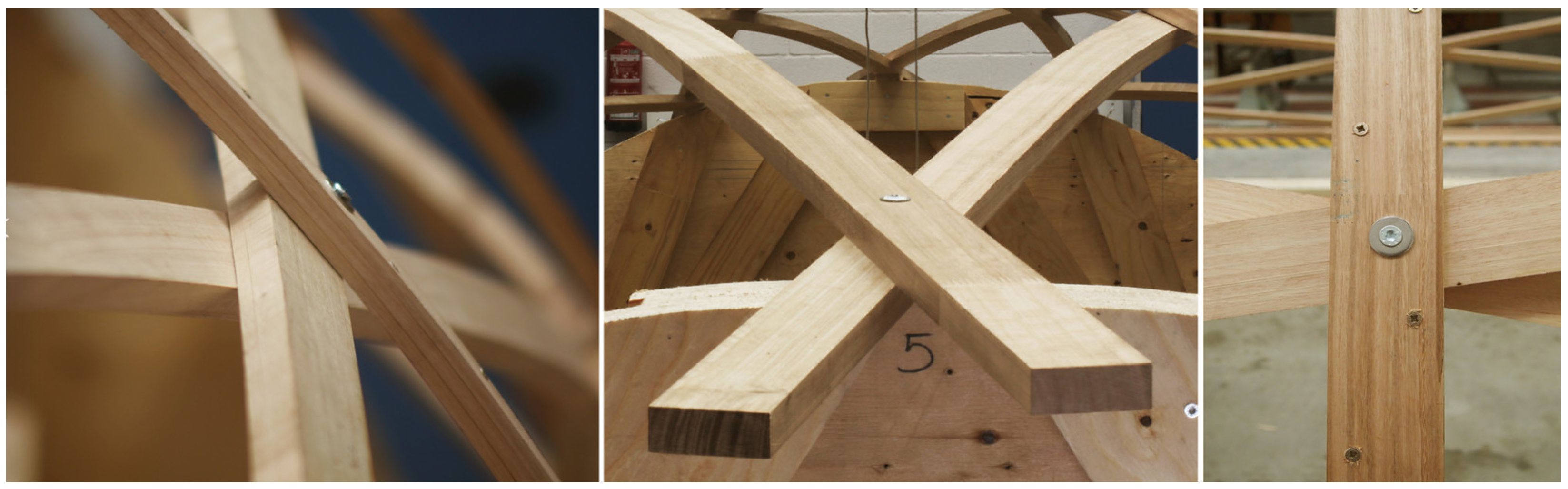
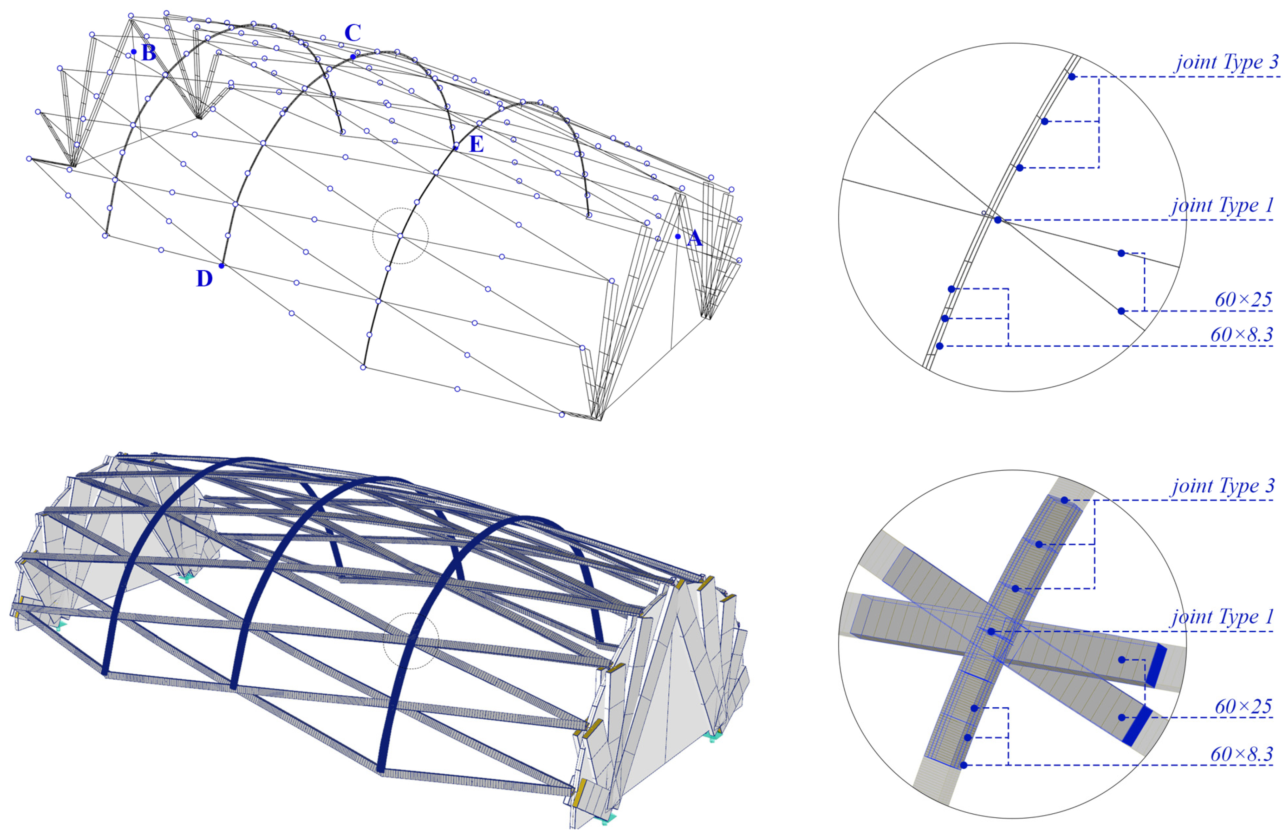
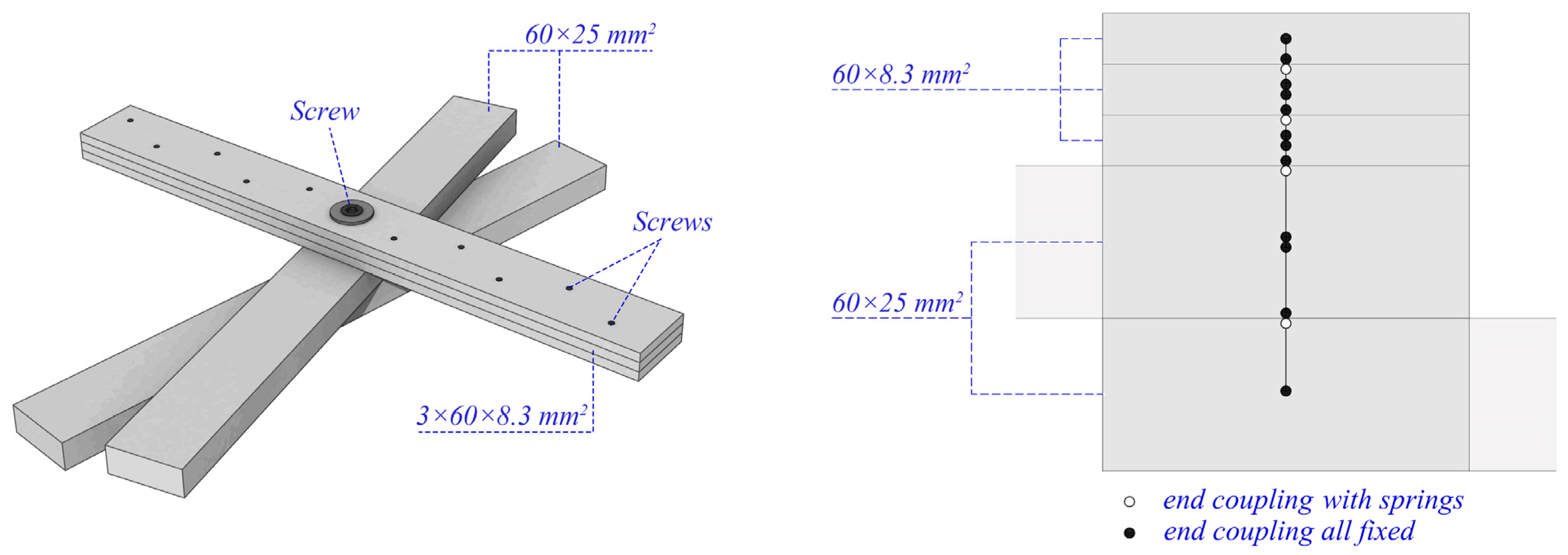
The main family of laths was discretised into six segments in each span between nodes. Rotation around the weak axis of the cross-section was allowed at the end nodes of each of the 18 laths. The transverse laths were discretised into segments of 60 mm in length, corresponding to the screw spacing of the Type 3 joint. The cross-section of each member segment was oriented so that the weak axis coincided with the vector normal to the surface at the centre point of each segment.
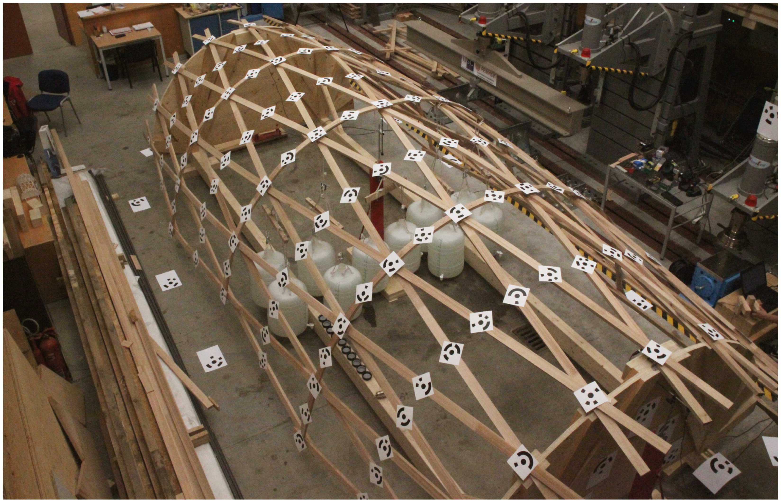
The points corresponding to each target (deformation control points) were implemented in the numerical model using small beam members that perpendicularly join the lath axis with the point corresponding to the centre of each target. In this way, a total correspondence was achieved between the coordinates of the targets in the numerical model and those obtained from the photogrammetry. This strategy also made it possible to detect the rotation by torsion of the members even if their ends do not move (Figure 9).
After completion of the geometrical model in Rhino, it was exported to RFEM (Dlubal Software GmbH, Tiefenbach, Germany) [46], where all necessary structural information was added. The timber laths were modelled as beam elements (with axial, shear, bending and torsional stiffness), to which the actual cross-section and average elastic properties were assigned.
The LVL supports were modelled as shell elements of 40 mm thickness. The shells were meshed so that one of their nodes coincided with the position of the LVDTs (control points A and B). The meshing of these elements was performed automatically in RFEM allowing triangular and quadrangular elements with a maximum side length of 0.5 m. No mesh refinement was applied. The reinforcement pieces were modelled as beams in their actual position, which were connected to the shell using small couplings. The general appearance of the developed geometrical and FEM models of the TEL-gridshell, including the location of control points A, B, C, D and E, and the detail of a nodal joint can be seen in Figure 10.
Linear and elastic material behaviour was assumed. The material properties of the beams are summarised in Table 4. For the shells, 2D orthotropic elastic material was taken. The average values of the mechanical properties of eucalyptus have been obtained from tests carried out by the authors (see Section 3.2), while those of pine LVL have been taken from data provided by the manufacturer (Metsä Wood, Espoo, Finland) [
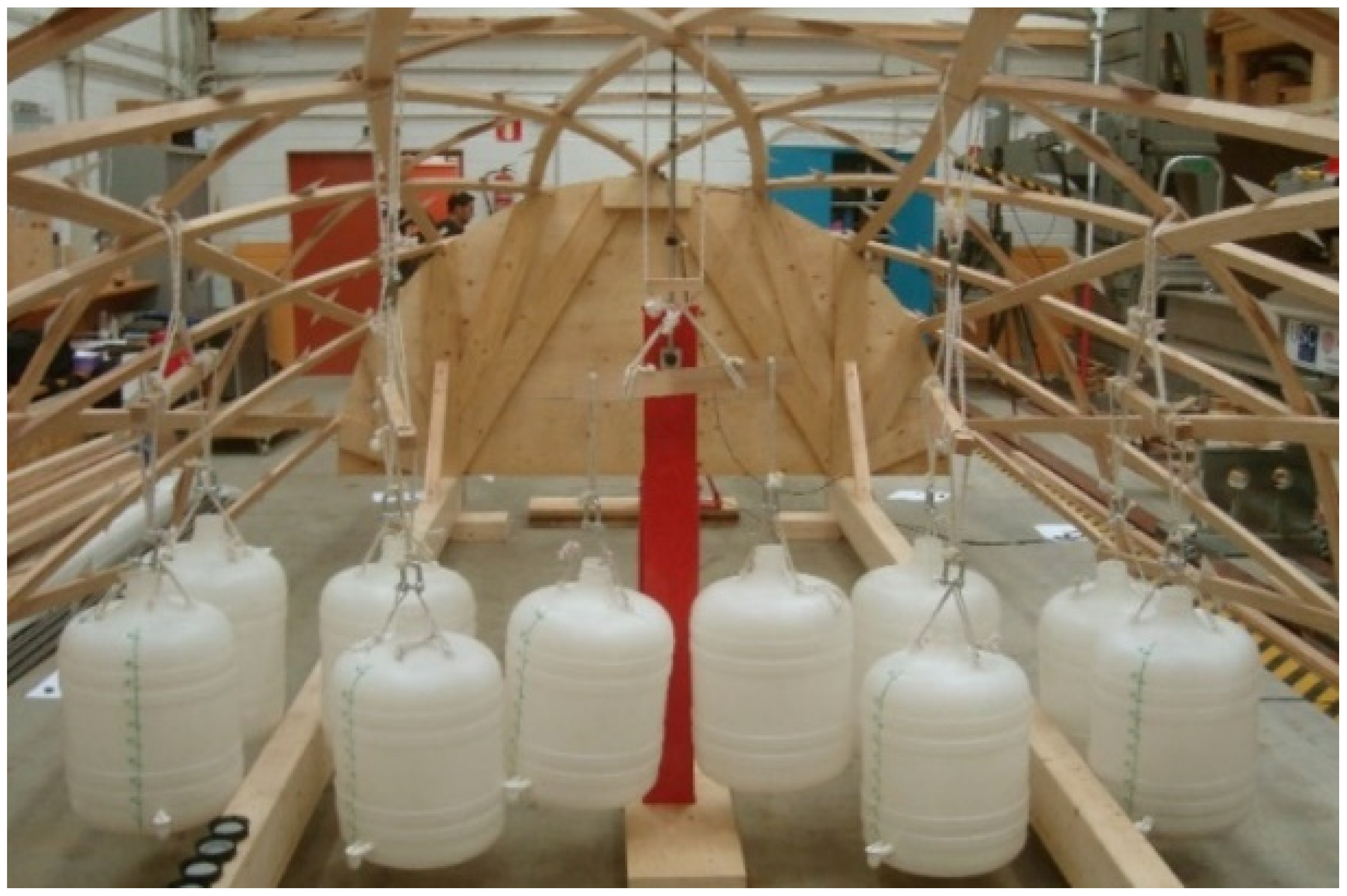
47]. The external loads were applied as point loads at the upper nodes of the corresponding joints. These were applied incrementally in eight steps until the experimental test load was reached. Geometrically non-linear large deformation analysis was performed.
To better understand the behaviour of the structure, the influence of the LVL supports and the stiffness of the joints on the overall stiffness of the gridshell was analysed. For this purpose, several numerical models (with and without LVL supports, and with and without slip) were developed for the three types of joints defined. The models considered are compiled in Table 5. Non-slip joints modelled without springs are defined as “Rigid”.

4.4. Experimental Results and Comparison with Numerical Analysis

The experimental displacements of the gridshell prototype points where the targets were placed were easily calculated from the coordinates of these points before and after loading. The average displacement of all nodes was 10.22 mm. The displacement vectors of the target points in the different numerical models were also obtained. Comparison of the experimental and numerical displacement values for the 145 measured points is shown in Table 6. The first row shows the sum of the displacements in absolute value for all nodes, Σ|U|. It provides an overview of the deformability of the structure. The second row presents the ratio of the above parameter for each numerical model in relation to the experimental one, Σ|U|num/Σ|U|exp. The third row gives the value of the mean displacement at each point, |U|mean. The following five rows show the displacements corresponding to the control points A–E presented in Table 2. The last rows show the deviation of the numerical results with respect to the experimental ones, providing the absolute difference between the experimental and numerical displacement vectors, |Uexp − Unum|, and the angle (in absolute value) formed by their directions.
As can be observed from Table 6, the C5 model, which incorporates the LVL supports and semi-rigidity in all joints, gives the best results. For this model, the calculated gridshell deformation shows reasonable agreement with the experimental values. The mean displacements are in the same range as the actual ones with a mean error of 1.85 mm and a standard deviation of 1.6 mm. This numerical error is very close to the mean error of the experimental measurement (1.63 mm, see Section 3.6), so better fittings of the numerical model are difficult to quantify.
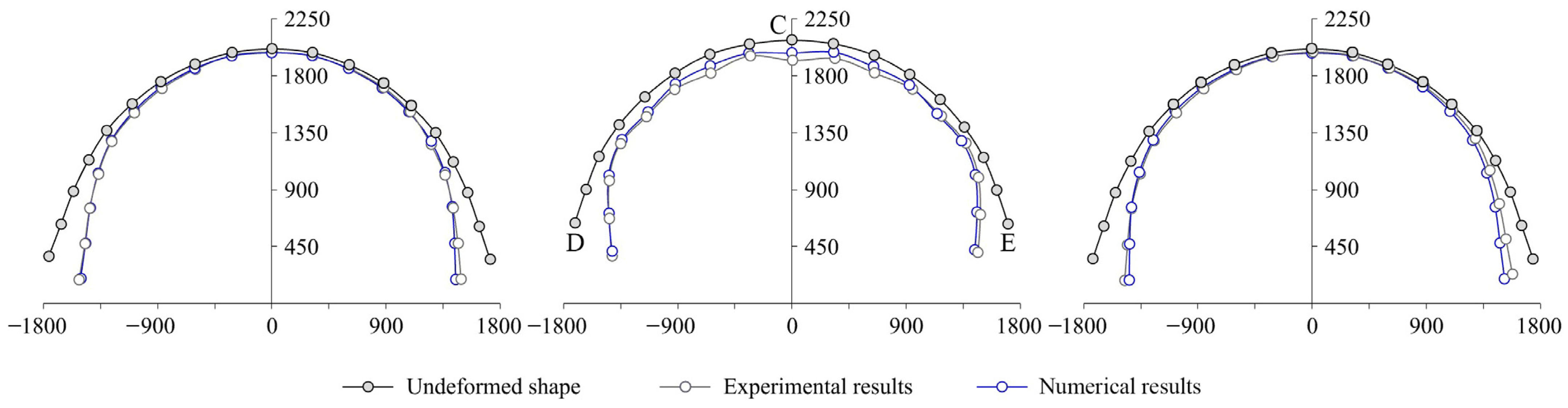
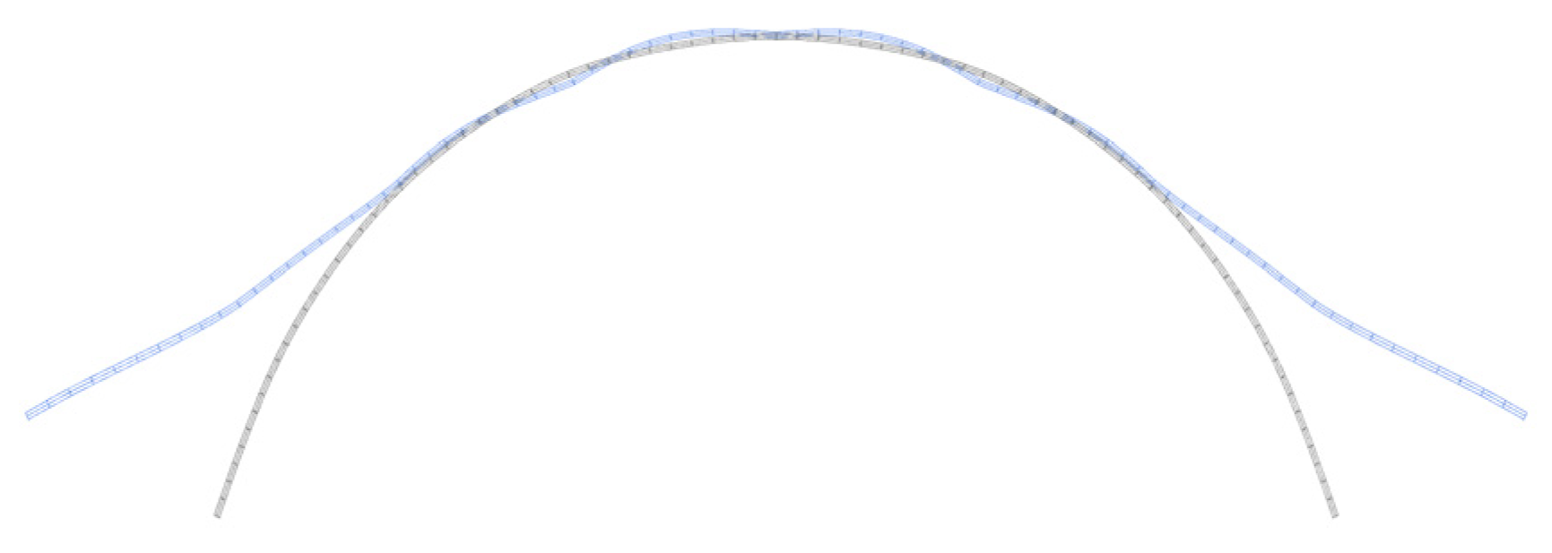
Figure 11 shows the final global deformations of the C5 model. For easier comparison with the experimental results, the three transverse laths of this model are presented in Figure 12.
As can be seen, the deformations at the load application points resulted greater in the experimental test than in the numerical model. Although the maximum experimental displacement in this area was 13.8 mm (14.6 mm from LVDT measurement), which is below the maximum value corresponding to SLS (L/300 = 21.7 mm), the stress in the joints may exceed their service range due to the application of heavy concentred loads. This could lead to local effects not considered in the model, such as non-linearity phenomena in the slip of the joints. To improve the model fitting in this respect, experimental studies of the joints would be necessary to determine their stiffness over the entire load range and to implement non-linear laws for the behaviour of the springs.
It should be noted that the greatest displacements of the structure do not occur in the load application points, but in the lower part of the transverse laths, which close inwards when the vertical loads are applied.
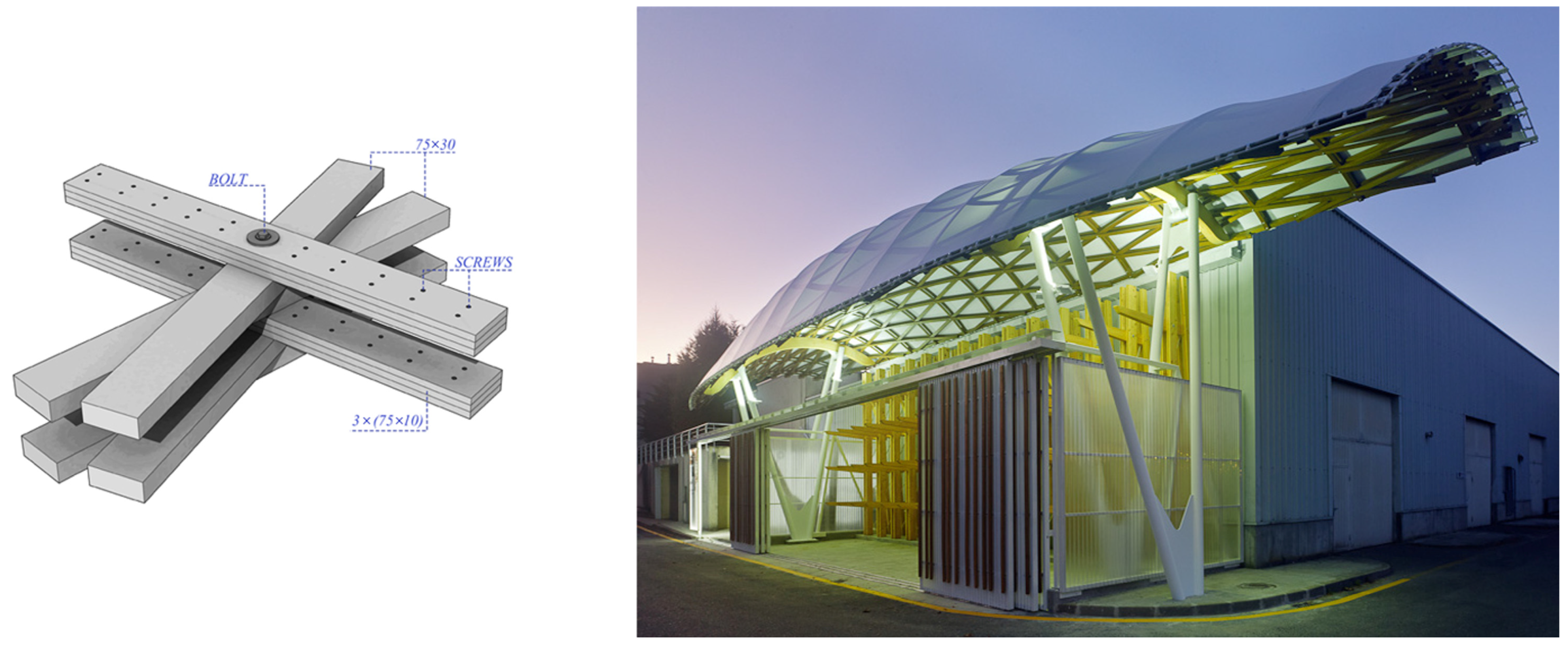
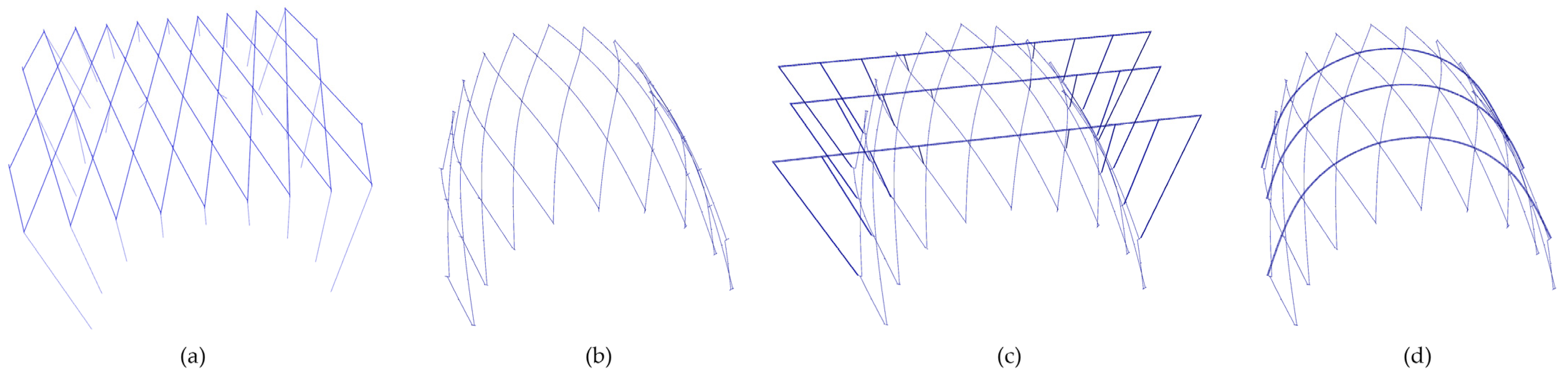
This behaviour highlights the lack of stiffness of the structure in this area, and points to the need for design modifications. Numerical simulations carried out by the authors have shown that an increase in the cross-sections of the longitudinal laths had practically no influence in this respect [11]. To increase the gridshell stiffness in that area, it is necessary to have an edge beam of large cross-section or to increase the moment of inertia of the transverse laths. The latter solution was used in a first permanent TEL-gridshell structure designed by the authors, in which double transverse laths were arranged (Figure 2 and Figure 13).
Analysing each of the different aspects involved in stiffness separately, it is observed that the addition of the LVL supports in the model is the most important to properly simulate the stiffness of the structure. The S5 model, without LVL supports but with slip at all joints, showed an average displacement much lower than that of any other model including LVL supports, even lower than that of the C1 model with all rigid joints. In particular, when comparing the S5 model with its counterpart C5 with supports, the mean displacement of the latter was more than three times higher than that of the former.
Likewise, the assumption of semi-rigidity at the nodal joints and supports in the model is of relevant importance to adjust the stiffness of the structure. As can be seen in Table 6, the gridshell with LVL supports and semirigid Type 1 and Type 2 joints (C4 model) had a 40% higher |U|mean than the same structure with all rigid joints (C1 model).
In short, similar to what happens in arches where their behaviour is strongly dependent on the stiffness of their supports, the gridshell under study requires the most accurate modelling possible of both the supporting structural elements and the connections of the laths resting on them. From a design point of view, it is a priority to provide the lateral supports and their connections with the maximum possible stiffness in order to minimise the deformations of the structure.
The relative influence of considering the stiffness of the mechanical laminate joints in the transverse laths (joint Type 3) can be analysed by comparing models C1, C2 and C3. As can be observed, the semi-rigidity of the nodal joints (C2) increases the displacement values more significantly than the consideration of semi-rigidity in the transverse laths (C3). The latter is the least influential variable on the overall stiffness of the prototype. Similar conclusions from a qualitative point of view are obtained by analysing models without the LVL supports, which are ultimately equivalent to structures with rigid supports. A parameterised study of all geometric and stiffness variables would be necessary to generalise these statements for TEL-gridshells.
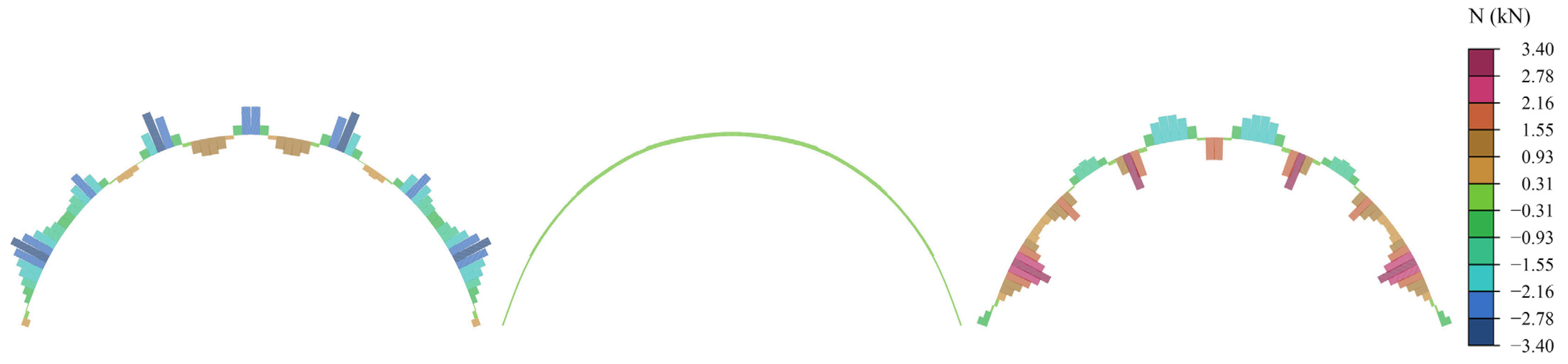
In order to have an approximation of the stress level reached in the prototype members due to the external load alone, the stresses obtained numerically are also analysed. The stresses have not been verified with any experimental procedure, but since the deformation obtained with model C5 provides a reasonable agreement with the experimental deformation, it is reasonable to think that the stresses obtained with this model also offer an adequate approximation.
Table 7 summarises the maximum values of axial forces (N), weak/strong axis bending moment (My and Mz, respectively), torsion moment (Mt), and weak/strong axis shear force (Vy and Vz) obtained with model C5. The results using model C1 (with all rigid connections) are also shown to better understand the influence of the joint stiffness on the stresses of the members.
As can be seen, in the model without slip at the joints (C1), the bending stresses due to My and Mz are 90% and 65% of the model with slip (C5), respectively. In contrast, the axial stresses are approximately 13% higher. Higher axial stresses and lower bending stresses are always desirable in the design of gridshell structures, as they lead to a better behaviour of the structure as a membrane and, consequently, to greater material savings. From a design point of view, this consideration is crucial and points out the importance of reflecting on the type of connection to be used, looking for high stiffness solutions.
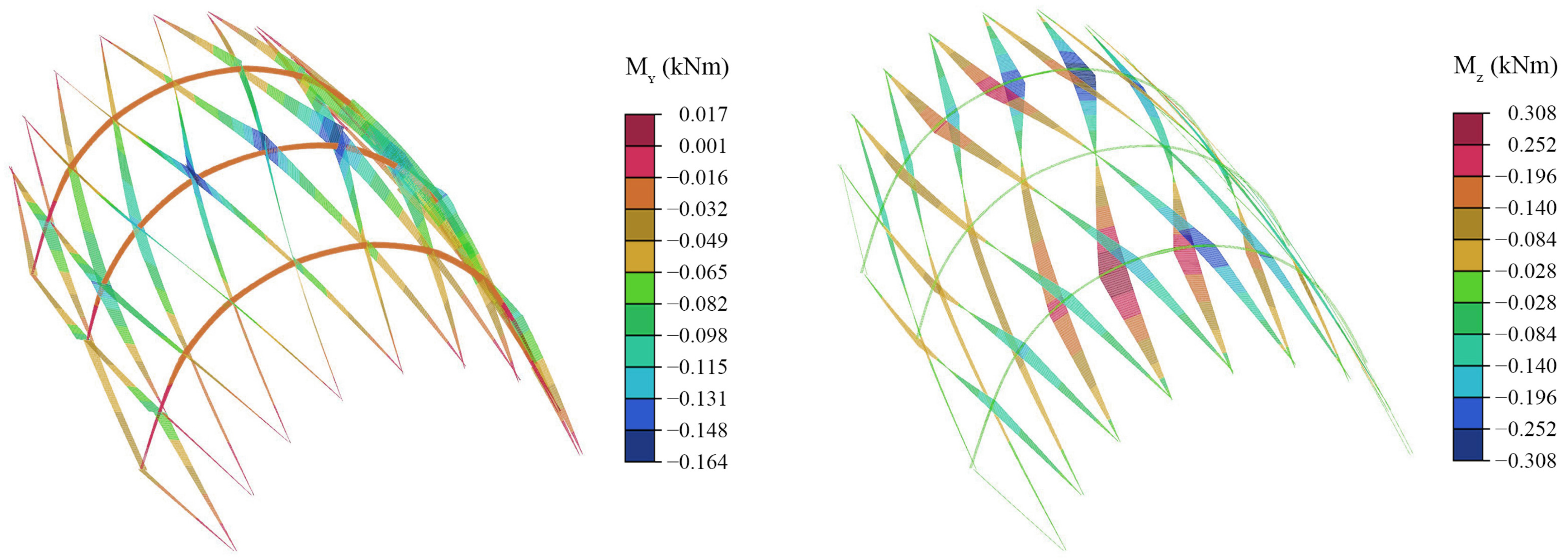
In general, the stresses in the structure are small, with maximum values in the zone of application of the point loads. Focusing on the results of model C5, the maximum values of combined normal stresses produced by the simultaneous action of axial and bending stresses (N, My and Mz) resulted in 11.5 N/mm2 for the longitudinal grid laths and 20.0 N/mm2 for the laths of the transverse laths. These are located in both cases in the kidney area of the central transverse lath, where the deformation due to curvature in the weak axis is more pronounced (see Figure 12). In fact, normal stresses due to My are responsible for more than 70% of the maximum combined normal stress in the case of longitudinal laths and 85% in the case of transverse laths.
The maximum shear stresses due to Vy and Vz are also small. The maximum value of 0.39 N/mm2 occurs in the transverse laths, in the same area as the maximum combined normal stress. The tangential stress due to Mt is very low and does not exceed 0.20 N/mm2 at any point.
In relation to the stresses in the joints, Table 8 shows the maximum shear Vj obtained in each type, calculated as (Vy2 + Vz2)0.5. As expected, shear values are higher in the model without slip than with slip. It should be noted that the maximum value of Vj in the nodal joints (Type 1 and Type 2) is only between 5% (Type 1) and 22% (Type 2-Spring 2B) higher in model C1 than in model C5, while it is more than twice as high in the case of the screws of the mechanical laminate of the transverse laths (Type 3 joint).
The results presented in this section do not take into account the stresses generated by the construction process. These are discussed in the next section.

5. Numerical Modelling for Form-Finding of TEL-Gridshells

In this section, a form-finding FEM model is presented to simulate the construction process of triaxial elastic long-gridshells supported on the short sides including the multilayered transverse laths, with emphasis on the residual stresses generated during the process. In addition, the structural behaviour of the bracing system and the movement of the structure after relaxation are analysed. The simulation reproduces the erection process of the laboratory prototype presented in previous sections. For this purpose, a customised model is developed with five intermediate stages in which the structural elements are progressively incorporated, and different auxiliary elements are activated and deactivated to simulate the bending process. This bending process is carried out by means of a provisional system of supports and contraction cables with reduced stiffness together with a system of couplings that are activated at the end of the bending process to connect the different structural elements.

5.1. Geometry, Materials and General Aspects

Geometrical modelling was performed completely in Rhino/Grasshopper. For the development of the computational model, the RF-Stages module of RFEM (Dlubal Software GmbH) was used, which allows the integration of the structural analysis of different construction stages in a single run analysis, considering large deformations. For each stage, 100 load steps (500 steps for the whole analysis) were set up, making a high resolution for the results with a short computational time. The target geometry of the grid was obtained from the design, not from photogrammetry. The type of element used to model the laths, the discretisation, the materials and the connection model (based on couplings with springs) are similar to those described in the previous section, so only the additional specific aspects related to the simulation of the construction process of the structure are shown here.

5.2. Form-Finding Stages

The main aspects of each erection stage defined in the numerical model are described below:
  • Stage 1. Grid bending (Figure 14a,b). In this stage, the grid bending is modelled from its initial position at the top of the structure until its complete deformation (Figure 3). For this purpose, the grid is modelled plane and positioned at the top of the built structure. For reasons of computation time, the grid is modelled semi-open instead of closed. The grid is linked to a support located in the centre of the grid, which prevents its displacement but allows it to rotate around a vertical axis. At this stage, rotation around the longitudinal axis of the couplings is allowed (see Figure 7), but the springs at their ends remain deactivated. The ends and points of the transverse midplane of the grid are pulled to their final coordinates by means of very low stiffness contraction cables which are shortened to almost zero length by an imposed axial deformation ε = −0.999 on each of them. For reasons of numerical stability, ε cannot be one and therefore the length of the cables is never completely zero;
  • Stage 2. Grid support. The cables from the previous stage are deactivated, and the definitive grid supports located at the ends of the laths are activated. Provisional supports are also activated at the internal crossing points of the deformed grid. This is essential to keep the grid position fixed until the transverse laths are added;
  • Stage 3. Bending of transverse laths (Figure 14c,d). The multilayer transverse members are modelled straight and placed tangent to the grid in the appropriate position. For the bending of these transverse members, contraction cables are also used, which pull the nodes of the three laths forming each of them into their deformed position in the grid. The coordinates of the target points of the nodes of each of the laths are easily obtained by placing auxiliary bars perpendicular to the grid at the corresponding nodes;
  • Stage 4. Connection. The cables from the previous stage are deactivated and a new coupling system is activated to connect the transverse members to the grid, and the couplings of the three layers of the transverse members to each other. The springs at the ends of the couplings corresponding to the Type 1, Type 2 and Type 3 joints, described in the previous section, are also activated;
  • Stage 5. Relaxation. Finally, all the provisional supports used in previous stages are deactivated. The gridshell relaxes and reaches a new equilibrium position as a result of the internal forces of elastic deformation and the slipping produced in the joints.

5.3. Workflow

The proposed form-finding model for TEL-gridshells requires determining the geometry of the elements in two steps with the help of an intermediate run analysis.
In the first step, the geometry of the main grid and the auxiliary elements corresponding to Stages 1 and 2 are established. The model is then imported into RFEM and a first provisional analysis is performed.
Once the deformed geometry of the grid is obtained, it is exported to Rhino where the geometry of the transverse laths in the deformed position is determined and, from this, the geometry of the straight laths including the position of the connectors is derived. Then, the cables required for the curving of the transverse laths and the auxiliary connectors needed to join all the elements are added to the geometrical model. These operations are carried out using custom scripts developed in Grasshopper. Once the geometrical model is complete, it is exported back to RFEM and the final full computational run analysis is performed (Stages 15).
The two-step geometrical modelling is necessary because the shortening of the cables is not total, and therefore the deformed grid does not exactly match the target grid. This means that the length of the transverse laths to be used does not match the length of the target geometry either and must be slightly readjusted. Otherwise, the length of the transverse laths will be longer than the distance in the grid and unrealistic stresses or convergence problems may occur.

5.4. Residual Stresses

The applied method allows the elements of the structure to be deformed elastically until the target geometry is reached (Stage 4) and, consequently, it also makes it possible to obtain the internal stresses at each point of the structure due to the deformation process. Furthermore, after the relaxation phase (Stage 5), it allows estimating the final shape of the structure and the final stresses in both members and joints. For the sake of clarity of the results, the self-weight of the structure is not taken into account in this section.
To analyse bending stresses due to curving in the target geometry (Stage 4) as well as changes in shape and residual stresses after the relaxation process (Stage 5) including slip at the joints, the results obtained for the structure in both stages are compared (model A). The stiffness values assigned to the springs are the same as in the previous section (see Table 5).
Table 9 shows the displacement values in model A at control points C and D–E (see Section 3.6), the maximum values obtained for N, My, Mz and Mt of the longitudinal grid members, and N and My in the transverse laths (Mz and Mt are null). Results are shown before and after relaxation (Stages 4 and 5).
As can be seen from the above results, the maximum moments My, Mz and Mt of the main grid are almost identical for Stages 4 and 5. This is because, in general, the movements produced after relaxation of the structure are actually very small and similar in both cases. When the inner links are deactivated, the grid moves slightly until it reaches a new equilibrium position.
Movements occur mainly in the area where the structure has the lowest stiffness, which, as discussed in the previous section, corresponds to the central area of the longitudinal lateral edges. The maximum displacements occur at control points D and E, which have practically identical moduli as they are symmetrical, and the model does not consider imperfections. These points were displaced by 18.4 mm. This displacement is not negligible, so again there is a need to increase the stiffness of the structure in this area.
Figure 15 shows the residual bending moment after the relaxation process. The longitudinal laths show high curving moments in the two axes of inertia. This is because their longitudinal axes are not geodesic curves of the structure surface. The maximum weak axis bending moment (My) of the longitudinal laths occurs in the area of the central transverse lath and has a value of 0.164 kNm, which produces a maximum bending stress of 26.24 N/mm2.
On the other hand, the strong axis bending moments (Mz) of the main laths are maximum in the vicinity of the other two transverse laths, with a maximum value of 0.308 kNm and a stress of 20.53 N/mm2, being zero in the area near the central transverse lath. The maximum value of the stress produced by both bending moments in the longitudinal laths is 33.97 N/mm2 and is located in the section of maximum Mz.
The longitudinal laths also exhibit normal stresses due to axial forces, but these are very low compared to those caused by bending. Specifically, the normal stress corresponding to the maximum axial force (1.984 kN compression) is only 1.32 N/mm2 and is located in a different section from the maximum combined bending section, which happens to be the maximum combined normal stress section.
The shear stresses produced by the construction process are moderate and do not require special attention during the design process.
The maximum torsional moment is 0.032 kNm, producing a maximum shear stress of only 1.39 N/mm2. The maximum stresses due to shear forces (Vy and Vz) are practically negligible, not exceeding 0.2 N/mm2.
Table 10 summarises the maximum shear forces Vj in the different type of joints produced during the construction process.
The effect of the bracing system on the structural behaviour of gridshells has been studied by several authors. It is essential to provide in-plane shear stiffness, significantly reducing deformations under external loads [3,40] and therefore considerably increasing the critical buckling load. However, the influence of the bracing system on the final shape of the structure and on the distribution of residual stresses in the members is a subject that has been little addressed in the literature. Moreover, in the specific case of the TEL-gridshells, the analysis of the bracing system requires special attention since it is formed by strongly curved laths and, therefore, with very high bending stresses. Thus, in order to better understand the influence of the bracing system in this type of structure, the results of the full structure model (model B) are compared with those of the model without transverse laths (model C) resulting from the elimination of Stages 3 and 4. In both cases, slip-free connections are considered.
Table 11 shows the displacements of models B and C at control points C and D–E, as well as the maximum values obtained for the stresses N, My, Mz and Mt in the longitudinal members of the grid. The results are shown before and after relaxation (Stages 4 and 5).
As is obvious, in Stage 4 before relaxation, the position of the nodes of both models is identical. In model C, without bracing system by removing the supports that hold the nodes in the target position, the whole structure deforms considerably.
In model C, the central point (control point C) descends 48.2 mm (L/135) and the curvatures of the laths in both axes are reduced, and consequently also the bending moments. The grid tends to return to the initial flat position, deforming more in the area where it is not bound, i.e., in the central strip of the structure. The quadrilaterals tend to close in the transverse direction of the grid, decreasing the length of their short diagonal. However, in the braced gridshell (model B), the overall geometry remains almost undeformed (except in the lower area of the transverse members, where there is a maximum displacement of 16.2 mm). The central point descends only 0.1 mm, and the bending moments before and after relaxation are practically the same. The final geometry of the structure after relaxation for both models is shown in Figure 16.
The elements of the bracing system triangulate the quadrilaterals of the grid maintaining their shape. As the quadrilaterals tend to close, the bracing is compressed. As the bracing is formed by curved transverse laths (not by cables or straight bars), the axial compressive forces produce bending moments in them which increase their curvature. Conversely, the elastic recovery moments of the laths tend to decrease the curvature. Figure 17 shows the final shape of the central traverse lath of the braced structure (model B) after relaxation.
Since the transverse members are made up of three mechanically joined laths, the resulting bending stresses are translated into normal stresses distributed in each of them (Figure 18), whose maximum compression value reaches 3.34 kN in model B, producing a compressive stress of 7.0 N/mm2.
In the case of the structure with slip (model A), the distribution of normal stresses in the laths of the transverse members is very similar to the previous case without slip, but the values are reduced by around 80% producing a maximum stress of 5.5 N/mm2, which represents a low value in relation to the material strength. It should be noted that the stresses produced by the curving moment (My) of the transverse member’ laths are much more important. This is practically constant along the member (see Figure 16) with a value of 0.033 kNm (see Table 9), which produces a maximum bending stress of 53.1 N/mm2, almost 10 times higher than those produced by the axial forces and close to the characteristic bending strength of the material.
It should be kept in mind that the calculated stresses correspond to the initial instant of curving. However, as explained in Section 3.5, the load test was carried out one week after the prototype construction was completed, allowing part of the stresses due to curving to dissipate because of the rheological behaviour of the wood. A discussion on the long-term evolution of bending stresses and the consideration of rheological effects of wood in the sizing of laths under constant deformation can be found in [24].

6. Conclusions

This work presents the most relevant aspects of the structural behaviour of triaxial elastic long-gridshells made of timber (TEL-gridshells), an innovative gridshell concept that uses three directions of bent laths and rests exclusively on its short sides.
The construction and load testing of a full-scale TEL-gridshell laboratory prototype have demonstrated the feasibility of the concept and served as a basis for the development of the numerical models.
FEM models are presented for structural analysis and form-finding of TEL-gridshells, considering the actual eccentricity and slip at the joints by means of a series of aligned couplings with springs.
The results of the first model, which replicates the actual geometry of the lab prototype obtained from experimental measurements, show that the most influential aspect on the overall deformability of the TEL-gridshells is the integration of the supporting structural elements, followed by the consideration of the semi-rigidity of the grid nodal joints. The incorporation of the semi-rigidity of the transverse members’ joints has turned out to be the least relevant aspect. A reasonably good fit between numerical and experimental results has been achieved when the supporting structural elements of the TEL-gridshell and the semi-rigidity of all joints, considering a linear behaviour of the latter, have been included in the model.
The second model developed proposes a methodology to reproduce the construction process of TEL-gridshells. It is based on an analysis by stages at large deformations using temporary supports and contraction cables with reduced stiffness to produce the deformation of the elements, and a system of additional couplings to connect the elements to each other after the curving process. The methodology has been successfully implemented in the simulation of the prototype construction and has proven to be a viable procedure for form-finding and for determining the residual forces of this type of structure.
Numerical analyses have provided further insight into the structural behaviour of TEL-gridshells. A parametric analysis would be necessary to draw general conclusions. However, the results obtained allow pointing out some of the main aspects to be considered in the design and structural analysis of this specific type of gridshells:
  • Transverse members are essential to maintain the target shape of the grid. They take on non-negligible normal stresses after the formwork is removed (relaxation);
  • These structures have a natural lack of out-of-plane bending stiffness at the longitudinal edges. It is important to consider some solution to increase the stiffness in this area, such as additional layers in the transverse members;
  • The stiffness of the structure is strongly influenced by the stiffness of the supporting elements. It is necessary to incorporate these elements in the numerical model to analyse the deformability of the structure. From a design point of view, it is advisable to look for solutions with the highest possible stiffness;
  • Higher joint stiffness increases axial forces and decreases bending forces in the members, which is generally desirable;
  • The worst stresses in the members correspond in general to the construction process. The most critical elements are the transverse members, which require the most attention in the design process of this type of structure. Despite being made up of thin laths, they have the highest curving stresses due to their small curvature radius. In addition, they also exhibit the highest bending stresses under external loads;
  • The longitudinal grid members have significant bending moments in both strong and weak axes due to the construction process. However, due to the external loads, bending occurs mainly in the weak axis. Grid geometries that minimise strong axis bending (e.g., geodesic curves) are desirable, as they significantly reduce the residual stresses due to the construction and thus increase the structural reserve of the laths under external loads;
  • The torsional stresses due to the forming process are much higher than those due to external loads (almost 10 times in the case of the prototype). However, these are not significant and do not pose a particular problem in the design process. In the case of cross-sections with larger width/depth ratios, this consideration should be reviewed. Shear forces due to the construction process are negligible, and those due to external loads are very low;
  • The stresses in the joints due to external loads are greater than those due to the construction process.
Although the work has focused particularly on the structural analysis of TEL-gridshells, the proposed modelling strategy could be applied to any type of elastic timber gridshell, which always presents eccentricity and slip at the joints. Furthermore, the model could be extended to other types of analysis, such as buckling, which is strongly dependent on the stiffness of the joints. Incorporating non-linear effects in the joint response could improve the results. This is very easy to do in the FEM environment used.

Author Contributions

Conceptualisation, A.J.L.-B. and M.G.; methodology, A.J.L.-B. and J.O.; validation, A.J.L.-B.; formal analysis, A.J.L.-B.; investigation, A.J.L.-B., A.M.-M. and J.O.; writing—original draft preparation, A.J.L.-B. and A.M.-M.; writing—review and editing, A.J.L.-B., A.M.-M., J.O. and M.G.; visualisation, A.J.L.-B.; supervision, M.G.; project administration, A.M.-M. and M.G.; funding acquisition, A.M.-M. and M.G. All authors have read and agreed to the published version of the manuscript.

Funding

Numerical research is part of the R&D&I Project PID2020-112954RA-I00 funded by MCIN/AEI/10.13039/501100011033. The experimental work is part of the R&D&I Project BIA2015-64491-P funded by MCIN/AEI/10.13039/501100011033 and by ERDF A way of making Europe.

Institutional Review Board Statement

Not applicable.

Informed Consent Statement

Not applicable.

Data Availability Statement

Not applicable.

Conflicts of Interest

The authors declare no conflict of interest.

References

  1. Quinn, G.C.; Gengnagel, C.; Williams, C.J.K. Comparison of erection methods for long-span strained grid shells. In Proceedings of the International Association for Shell and Spatial Structures (IASS) Symposium, Amsterdam, The Netherlands, 17–20 August 2015. [Google Scholar]
  2. Adriaenssens, S.; Barnes, M.; Harris, R.; Williams, C. Dynamic relaxation: Design of a strained timber gridshell. In Shell Structures for Architecture: Form Finding and Optimization; Adriaenssens, S., Block, P., Veenendaal, D., Williams, C., Eds.; Routledge: Abingdon, UK, 2014; pp. 89–102. [Google Scholar]
  3. Collins, M.; Cosgrove, T. Dynamic relaxation modelling of braced bending active gridshells with rectangular sections. Eng. Struct. 2019, 187, 16–24. [Google Scholar] [CrossRef]
  4. Hennicke, J.; Matsushita, K.; Otto, F.; Sataka, K.; Schaur, E.; Shirayanagi, T.; Gröbber, G. IL 10 Gitterschalen; Institut für Leichte Flächentragwerke (IL): Stuttgart, Germany, 1974. [Google Scholar]
  5. Happold, E.; Liddell, W.I. Timber lattice roof for the Mannheim Bundesgartenschau. Struct. Eng. 1975, 53, 99–135. [Google Scholar]
  6. Harris, R.; Kelly, O.; Dickson, M. Downland gridshell-an innovation in timber design. Proc. Inst. Civ. Eng.—Civ. Eng. 2003, 156, 26–33. [Google Scholar] [CrossRef]
  7. Harris, R.; Haskins, S.; Roynon, J. The Savill Garden gridshell: Design and construction. Struct. Eng. 2008, 86, 27–34. [Google Scholar]
  8. Gliniorz, K.-U.; Mosalam, K.M.; Natterer, J. Modeling of layered timber beams and ribbed shell frameworks. Compos. Part B Eng. 2002, 33, 367–381. [Google Scholar] [CrossRef]
  9. Natterer, J.; Burger, N.; Müller, A.; Natterer, J. Holzrippendächer in Brettstapelbauweise—Raumerlebnis durch filigrane Tragwerke. Bautechnik 2000, 77, 783–792. [Google Scholar] [CrossRef]
  10. Natterer, J.; Burger, N.; Müller, A.; Natterer, J. Roof of the Main Hall at Expo 2000 in Hanover, Germany. Struct. Eng. Int. 2000, 10, 167–169. [Google Scholar] [CrossRef]
  11. Lara-Bocanegra, A.J.; Roig, A.; Majano-Majano, A.; Guaita, M. Innovative design and construction of a permanent elastic timber gridshell. Proc. Inst. Civ. Eng.—Struct. Build. 2020, 173, 352–362. [Google Scholar] [CrossRef]
  12. Triaxial Gridshell of Eucalyptus (First Prototype Project). Available online: https://vimeo.com/252906184 (accessed on 14 April 2022).
  13. Design of the Triaxial Gridshell Prototype Project. Available online: https://vimeo.com/252746775 (accessed on 14 April 2022).
  14. Gliniorz, K.-U.; Hübner, L.; Natterer, J. Berechnung von Holzrippenschalen. Forschung und Entwicklungen an der ETH Lausanne. Bautechnik 2008, 78, 156–163. [Google Scholar] [CrossRef]
  15. DIN 1052; Entwurf, Berechnung und Bemessung von Holzbauwerken—Allgemeine Bemessungsregeln und Bemessungsregeln für den Hochbau. (in English: Design of Timber Structures—General Rules and Rules for Buildings); Deutsches Institut für Normung: Berlin, Germany, 2000.
  16. Naicu, D.-I. Geometry and Performance of Timber Gridshells. Master’s Thesis, The University of Bath, Bath, UK, 2012. [Google Scholar]
  17. Lefevre, B.; Douthe, C.; Baverel, O. Buckling of elastic gridshells. J. Int. Assoc. Shell Spat. Struct. 2015, 56, 153–171. [Google Scholar]
  18. Reindl, J.-O. Buckling Analysis of Cylindrical Elastically Bent Timber Gridshells. Master’s Thesis, Technical University of Munich, Munich, Germany, 2019. [Google Scholar]
  19. Fernandez-Cabo, J.L.; Fernandez-Lavandera, J.; Diez-Barra, R.; Avila-Jalvo, J.M. Timber composite beams with a discrete connection system. Proc. Inst. Civ. Eng.—Struct. Build. 2013, 166, 57–72. [Google Scholar] [CrossRef]
  20. Monteiro, S.R.S.; Dias, A.M.P.G.; Lopes, S.M.R. Bi-dimensional numerical modeling of timber–concrete slab-type structures. Mater. Struct. 2015, 48, 3391–3406. [Google Scholar] [CrossRef]
  21. Grönquist, P.; Panchadcharam, P.; Wood, D.; Menges, A.; Rüggeberg, M.; Wittel, F.K. Computational analysis of hygromorphic self-shaping wood gridshell structures. R. Soc. Open Sci. 2020, 7, 192210. [Google Scholar] [CrossRef]
  22. Lara-Bocanegra, A.J.; Majano-Majano, A.; Arriaga, F.; Guaita, M. Long-term bending stress relaxation in timber laths for the structural design of lattice shells. Constr. Build. Mater. 2018, 193, 565–575. [Google Scholar] [CrossRef]
  23. Roig, A.; Lara-Bocanegra, A.J.; Majano-Majano, A.; Guaita, M. Integrating design tools for elastic timber gridshells. In Proceedings of the World Conference on Timber Engineering (WCTE), Santiago, Chile, 9–12 August 2021. [Google Scholar]
  24. Lara-Bocanegra, A.J.; Majano-Majano, A.; Arriaga, F.; Guaita, M. Eucalyptus globulus finger jointed solid timber and glued laminated timber with superior mechanical properties: Characterisation and application in strained gridshells. Constr. Build. Mater. 2020, 265, 120355. [Google Scholar] [CrossRef]
  25. Schling, E.; Kilian, M.; Wang, H.; Schikore, J.; Pottmann, H. Design and Construction of Curved Support Structures with Repetitive Parameters. In Proceedings of the AAG 2018—Advances in Architectural Geometry, Gothenburg, Sweden, 22–25 September 2018. [Google Scholar]
  26. Lienhard, J.; Gengnagel, C. Recent developments in bending-active structures. In Proceedings of the IASS Annual Symposium, Boston, MA, USA, 16–20 July 2018. [Google Scholar]
  27. Bauer, A.M.; Längst, P.; La Magna, R.; Lienhard, J.; Piker, D.; Quinn, G.; Gengnagel, C.; Bletzinger, K.-U. Exploring Software Approaches for the Design and Simulation of Bending Active Systems. In Proceedings of the IASS Annual Symposium, Boston, MA, USA, 16–20 July 2018. [Google Scholar]
  28. Douthe, C.; Baverel, O.; Caron, J.-F. Form-finding of a grid shell in composite materials. J. Int. Assoc. Shell Spat. Struct. 2006, 47, 53–62. [Google Scholar]
  29. Quinn, G. Structural analysis for the pneumatic erection of elastic gridshells. Structures 2020, 28, 2276–2290. [Google Scholar] [CrossRef]
  30. Du Peloux, L.; Tayeb, F.; Lefevre, B.; Baverel, O.; Caron, J.-F. Formulation of a 4-DoF torsion/bending element for the formfinding of elastic gridshells. In Proceedings of the International Association for Shell and Spatial Structures (IASS) Symposium, Amsterdam, The Netherlands, 17–20 August 2015. [Google Scholar]
  31. Tayeb, F.; Lefevre, B.; Baverel, O.; Caron, J.F.; Du Peloux, L. Design and realisation of composite gridshell structures. J. Int. Assoc. Shell Spat. Struct. 2015, 56, 49–59. [Google Scholar]
  32. Barnes, M.R.; Adriaenssens, S.; Krupka, M. A novel torsion/bending element for dynamic relaxation modeling. Comput. Struct. 2013, 119, 60–67. [Google Scholar] [CrossRef] [Green Version]
  33. Li, J.-M. Timber Shell Structures: Form-Finding and Structural Analysis of Actively Bent Grid Shells and Segmental Plate Shells. Ph.D. Thesis, Universität Stuttgart—Institut für Tragkonstruktionen und Konstruktives Entwerfen, Stuttgart, Germany, 2017. [Google Scholar]
  34. Poulsen, E. Structural Design and Analysis of Elastically Bent Gridshells. Master’s Thesis, Chalmers University of Technology, Gothenburg, Sweden, 2015. [Google Scholar]
  35. D’Amico, B.; Kermani, A.; Zhang, H. Form finding and structural analysis of actively bent timber grid shells. Eng. Struct. 2014, 81, 195–207. [Google Scholar] [CrossRef] [Green Version]
  36. UNE-EN 1995-1-1; Eurocódigo 5: Proyecto de Estructuras de Madera—Parte 1-1: Reglas Generales y Reglas Para Edificación. (In English: Eurocode 5: Design of Timber Structures—Part 1-1: General. Common Rules and Rules for Buildings); AENOR: Madrid, Spain, 2016.
  37. Lafuente Hernández, E.; Baverel, O.; Gengnagel, C. On the Design and Construction of Elastic Gridshells with Irregular Meshes. Int. J. Space Struct. 2013, 28, 161–174. [Google Scholar] [CrossRef]
  38. Lafuente Hernández, E.; Gengnagel, C. Influence of Constructive Aspects on the Geometry and Performance of elastic Gridshells. In Proceedings of the IASS-APCS Symposium: From Spatial Structures to Space Structures, Seoul, Korea, 21–24 May 2012. [Google Scholar]
  39. Lienhard, J.; La Magna, R.; Knippers, J. Form-finding bending-active structures with temporary ultra-elastic contraction elements. WIT Trans. Built Environ. 2014, 136, 107–115. [Google Scholar]
  40. Douthe, C.; Caron, J.F.; Baverel, O. Gridshell structures in glass fibre reinforced polymers. Constr. Build. Mater. 2010, 24, 1580–1589. [Google Scholar] [CrossRef]
  41. UNE 56546; Clasificación Visual de la Madera Aserrada para Uso Estructural. Madera de Frondosas. (In English: Visual Grading for Structural Sawn Timber. Hardwood Timber); AENOR: Madrid, Spain, 2013.
  42. UNE-EN 408:2011+A1; Estructuras de Madera. Madera Aserrada y Madera Laminada Encolada para Uso Estructural. Determinación de Algunas Propiedades Físicas y Mecáncias. (In English: Timber Structures. Structural Timber and Glued Laminated Timber. Determination of Some Physical and Mechanical Properties); AENOR: Madrid, Spain, 2012.
  43. Lara-Bocanegra, A.J.; Majano-Majano, A.; Crespo, J.; Guaita, M. Finger-jointed Eucalyptus globulus with 1C-PUR adhesive for high performance engineered laminated products. Constr. Build. Mater. 2017, 135, 529–537. [Google Scholar] [CrossRef]
  44. Ortiz-Sanz, J.; Gil-Docampo, M.; Bastos, G. Inexpensive photogrammetry applied to displacement measurement of a gridshell. Measurement 2022, 111365. [Google Scholar] [CrossRef]
  45. Rhinoceros 3D; Version 6; Robert McNeel & Associates: Seattle, WA, USA, 2018.
  46. RFEM. FEM Structural Analysis Software; Version 5.27; Dlubal Software GmbH: Munich, Germany, 2021. [Google Scholar]
  47. VTT Certificate No. 184/03—Kerto-S and Kerto-Q Structural Laminated Veneer Lumber; VTT Expert Services Ltd.: Espoo, Finland, 2016.
Figure 1. Multilayer system in traditional elastic timber gridshells: (a) the Mannheim Multihalle; (b) the Weald & Downland Living Museum; (c) the Savill Garden; (d) the Polydôme EPFL.
Applsci 12 05335 g001
Figure 2. TEL-gridshell concept. Detail of the nodal joint (left) and general view of the first permanent TEL-gridshell (right).
Applsci 12 05335 g002
Figure 3. Construction process of the TEL-gridshell lab prototype.
Applsci 12 05335 g003
Figure 4. Joints of the TEL-gridshell lab prototype.
Applsci 12 05335 g004
Figure 5. Interior view of the TEL-gridshell lab prototype during the load test.
Applsci 12 05335 g005
Figure 6. TEL-gridshell lab prototype view with the photogrammetric measuring target points.
Applsci 12 05335 g006
Figure 7. Connector concept by coupling used for modelling of the joints.
Applsci 12 05335 g007
Figure 8. Joint Type 1. Layout detail and aligned couplings for the numerical model.
Applsci 12 05335 g008
Figure 9. Movement of a deformation control point (k) due exclusively to torsion in the lath.
Applsci 12 05335 g009
Figure 10. Geometrical (top) and numerical (down) models of the gridshell and detail of a nodal joint.
Applsci 12 05335 g010
Figure 11. Model C5. Undeformed geometry in lines and deformed geometry in coloured sections for point loads of 1.04 kN (amplification factor = 10).
Applsci 12 05335 g011
Figure 12. Experimental and numerical (model C5) deformation results of the three transverse laths of the TEL-gridshell (amplification factor = 10).
Applsci 12 05335 g012
Figure 13. Detail of the double transverse laths of the first permanent TEL-gridshell.
Applsci 12 05335 g013
Figure 14. Simulation of the construction process of the TEL-gridshell lab prototype: (a) and (b) grid bending; (c) and (d) bending of transverse laths.
Applsci 12 05335 g014
Figure 15. Model A with semi-rigid connections: residual bending moment.
Applsci 12 05335 g015
Figure 16. TEL-Gridshell geometry after relaxation, with bracing system (left) and without bracing system (right). Amplification factor = 5.
Applsci 12 05335 g016
Figure 17. Transverse lath before relaxation of the structure (Stage 4) in black, and deformed shape after relaxation in blue (amplification factor = 40).
Applsci 12 05335 g017
Figure 18. Model B: residual normal forces in the three laths forming the transverse members. Upper lath (left), middle lath (centre) and lower lath (right).
Applsci 12 05335 g018
Table 1. Minimum, maximum, average, and standard deviation (SD) values of the errors in the distances between five pairs of checking points for the unloaded and loaded states.
Unloaded StateLoaded State
Error (mm)Error (‰)Error (mm)Error (‰)
min0.930.110.990.11
max1.940.232.430.23
average1.41 1.63
SD0.45 0.48
Table 2. Displacement of the deformation control points A, B, C, D and E (in mm).
Control PointsABCDE
Photogrammetry14.6038.9732.71
LVDTs0.180.4513.80
Table 3. Stiffness of the springs.
d (mm)ρmean,1 (kg/mm3)ρmean,2 (kg/mm3)ρmean (kg/mm3)kiy = kiz = Kser
(N/mm)
Spring 167957957955848
Spring 2A87957957957797
Spring 2B87955106375589
Spring 347957957953898
Table 4. Material properties of Eucalyptus globulus and Pinus sylvestris LVL beam elements used in the numerical model: mean modulus of elasticity parallel to grain (E0,mean), mean shear modulus (Gmean), and mean density (ρmean).
E0,mean (N/mm2)Gmean (N/mm2)ρmean (kg/mm3)
Eucalyptus globulus beam17,544969795
Pinus sylvestris LVL beam13,800600510
Table 5. Numerical models analysed and stiffness values considered for each of the springs (N/mm).
Without LVL Supports (S-Models)With LVL Supports (C-Models)
S1S2S3S4S5C1C2C3C4C5
Kser,spring 1Rigid5848584858485848Rigid5848584858485848
Kser,spring 2ARigid7797779777977797Rigid7797779777977797
Kser,pring 2BRigidRigidRigid55895589RigidRigidRigid55895589
Kser,spring 3RigidRigid3898Rigid3898RigidRigid3898Rigid3898
Table 6. Comparison between numerical and experimental displacements.
Without LVL Supports (S-Models)With LVL Supports (C-Models)
Exp.S1S2S3S4S5C1C2C3C4C5
Σ|U| (mm) 1481.90189.9292.7296.9401.2404.9960.31163.41235.51350.91445.9
Σ|U|num/Σ|U|exp 0.130.200.200.270.280.650.800.850.920.98
|U|mean (mm) 10.221.312.022.052.772.796.668.028.529.329.97
|U|A (mm) 0.180.080.040.070.010.12
|U|B (mm) 0.450.250.400.450.380.44
|U|C (mm) 13.84.06.57.77.18.45.318.099.78.610.2
|U|D (mm) 38.974.036.497.728.148.4427.5230.4032.9734.9338.17
|U|E (mm) 32.713.14.54.67.67.926.729.432.034.037.2
|Uexp − Unum| (mm)mean 8.988.308.297.537.513.952.732.362.031.85
SD 8.48.18.17.47.43.02.31.81.71.6
CoV (%) 93.597.697.798.398.575.984.276.383.786.5
Angle (°)mean 40.736.436.123.722.920.418.017.418.618.0
Table 7. Maximum axial force (N), shear force (V) and bending moment (M) in the members from the load test.
N (kN)My (kNm) Mz (kNm)Mt (kNm)Vy (kN)Vz (kN)
C1Principal grid+2.630/−2.555+0.045/−0.046+0.023/−0.024 +0.002/−0.0030.0720.157
Transverse laths+3.021/−3.992+0.004/−0.005+0.011/−0.008+0.000/−0.0000.1030.132
C5Principal grid+2.332/−2.259+0.047/−0.051+0.031/−0.037+0.004/−0.0040.0770.155
Transverse laths+2.462/−3.469+0.006/−0.011+0.010/−0.005+0.001/−0.0010.0610.128
Table 8. Maximum stresses in the joints derived from the load test for models C1 (without slip) and C5 (with slip).
Type 1Type 2 (Spring 2A)Type 2 (Spring 2B)Type 3
C1Vj (kN)3.042.642.311.14
C5Vj (kN)2.902.301.890.52
Table 9. Model A (with semi-rigid connections). Displacements at control points C and D–E and maximum axial forces and moments due to the construction process, before relaxation (Stage 4) and after relaxation (Stage 5).
Before RelaxationAfter Relaxation
Control points|U|C (mm)0.00.1
|U|D–E (mm)0.118.4
Longitudinal gridN (kN)+0.590/−0.849+0.951/−1.984
My (kNm)+0.015/−0.164 +0.017/−0.164
Mz (kNm)+0.315/−0.315+0.308/−0.308
Mt (kNm)+0.033/−0.032+0.032/−0.030
Transverse lathsN (kN)+0.918/−0.397+2.472/−2.617
My (kNm)+0.006/−0.044+0.001/−0.033
Table 10. Model A (with semi-rigid connections). Maximum residual shear forces in the joints.
Type 1Type 2AType 2BType 3
Vj (kN)1.490.791.390.46
Table 11. Models B and C (with rigid connections). Displacements at control points C and D–E, and maximum axial force and moments in the longitudinal grid members due to the construction process, before and after relaxation.
Model B (with Bracing System)Model C (without Bracing System)
Before RelaxationAfter RelaxationBefore RelaxationAfter Relaxation
|U|C (mm)0.00.10.048.2
|U|D–E (mm)0.016.20.054.0
N (kN)+0.583/−0.842+1.062/−1.930+0.598/−0.801+1.206/−2.008
My (kNm)+0.015/−0.165+0.017/−0.165+0.015/−0.165+0.025/−0.131
Mz (kNm)+0.315/−0.315+0.312/−0.312+0.315/−0.315+0.289/−0.289
Mt (kNm)+0.033/−0.032+0.033/−0.031+0.033/−0.032+0.027/−0.043
Publisher’s Note: MDPI stays neutral with regard to jurisdictional claims in published maps and institutional affiliations.

