1. Introduction
In the 21st century world where science and technology are rapidly developing, the urban rail transit system represented by the subway has been vigorously developed, and gradually plays an increasingly important role in people’s lives, not only facilitating people’s lives, but also greatly promoting the economic growth [
1,
2,
3]. However, with the denser subway lines and the increase in train speed, the environmental vibration problem caused by subway train operations has gradually become prominent. When the subway train runs along the subway line, the train wheel–rail contact is accompanied by the track irregularity, which produces an excitation effect and, in turn, produces vibrations between the vehicle and the track structure. The vibration will be transmitted to the ground through the basic structure, and may even cause secondary vibrations of adjacent buildings and noise, which have a greater impact on the work and life of residents along the line and the precision instruments of certain scientific research institutes. For some precious ancient buildings, the secondary vibration may also have an adverse effect on the safety of the structure [
4]. Therefore, in the 20 years that the world has vigorously developed rail transit, the research on such issues has been extremely active. In most subway line segments, the ordinary monolithic track and the steel-spring-floating slab track are often laid alternately to ensure the vibration damping effect of the constructed line.
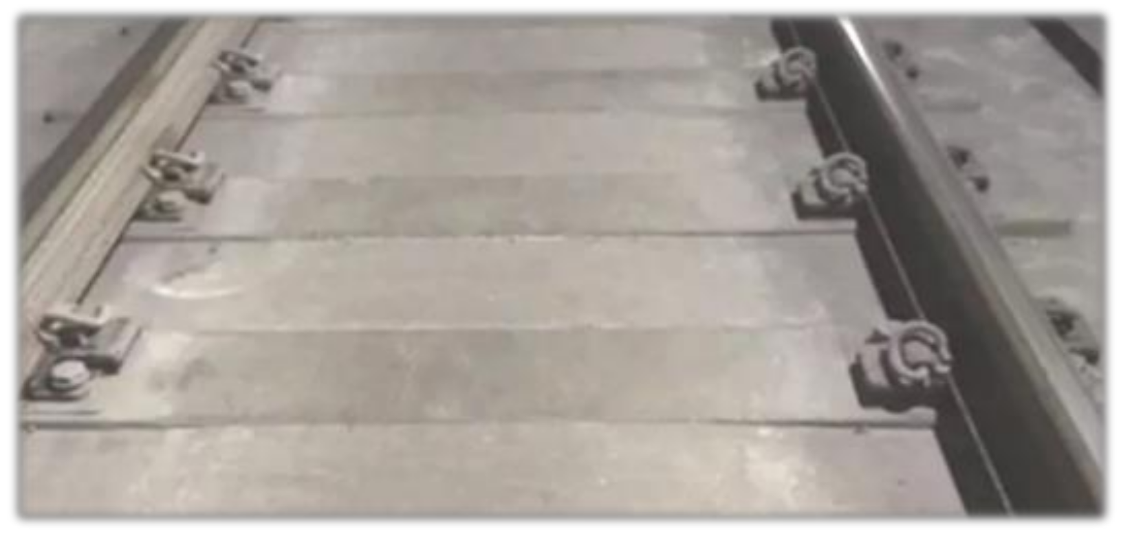
Ordinary monolithic track structure often adopts cast-in-place sleeper-embedded track bed structure (
Figure 1), which has good integrity and relatively low cost [
5]. For the ordinary monolithic track structure system used in the primary vibration damping area of the subway track structure, the elasticity of the lower part of the rail is mainly provided by the corresponding fasteners. The rail fasteners can be used to adjust the overall mechanical and material properties of the track and adapt to the track geometry. Therefore, the design and manufacturing requirements are relatively high. The fasteners often need to have enough buckle pressure to ensure the safety of the train during operation, and also need to have a certain vibration damping effect, and facilitate maintenance and repair [
6]. In this research, the vibration response of the ordinary monolithic track is used as a control group to compare the dynamic properties of the steel-spring-floating slab track.
For special places with high vibration damping requirements, subway lines generally adopt a steel-spring-floating slab track structure, as shown in
Figure 2. Its components include generally a concrete base, a steel-spring vibration isolator, a reinforced concrete floating slab, and fasteners. In this structure, elastic supports are added between the concrete bottom slab and the reinforced concrete floating slab [
7,
8,
9,
10]. The elastic support has a certain adjustment flexibility. Both sides of the floating slab are fixed with elastic materials, and the rail is fixed on the floating slab with fasteners. At the same time, in order to ensure the coordination of the overall rigidity of the floating slab track, shear hinge devices are also provided at the ends of the two floating slab tracks [
11,
12].
The steel-spring-floating slab track system is actually a mass-spring vibration isolation system [
13]. The vibration isolation method is to float a reinforced concrete track bed with a certain mass and rigidity on the vibration isolation element, and uses the slab and the vibration isolation element to form a mass spring [
14]. The vibration damping system adopts the mass inertia of the floating slab to balance part of the load of the train operation, and transfer the remaining load to the track bed, tunnel, and other structures to achieve the purpose of vibration damping [
15]. After analysis by researchers from various countries, the floating slab track is used as an important plan for the track vibration damping segment:
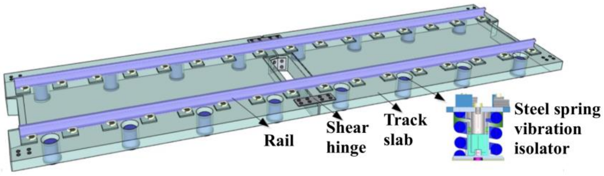
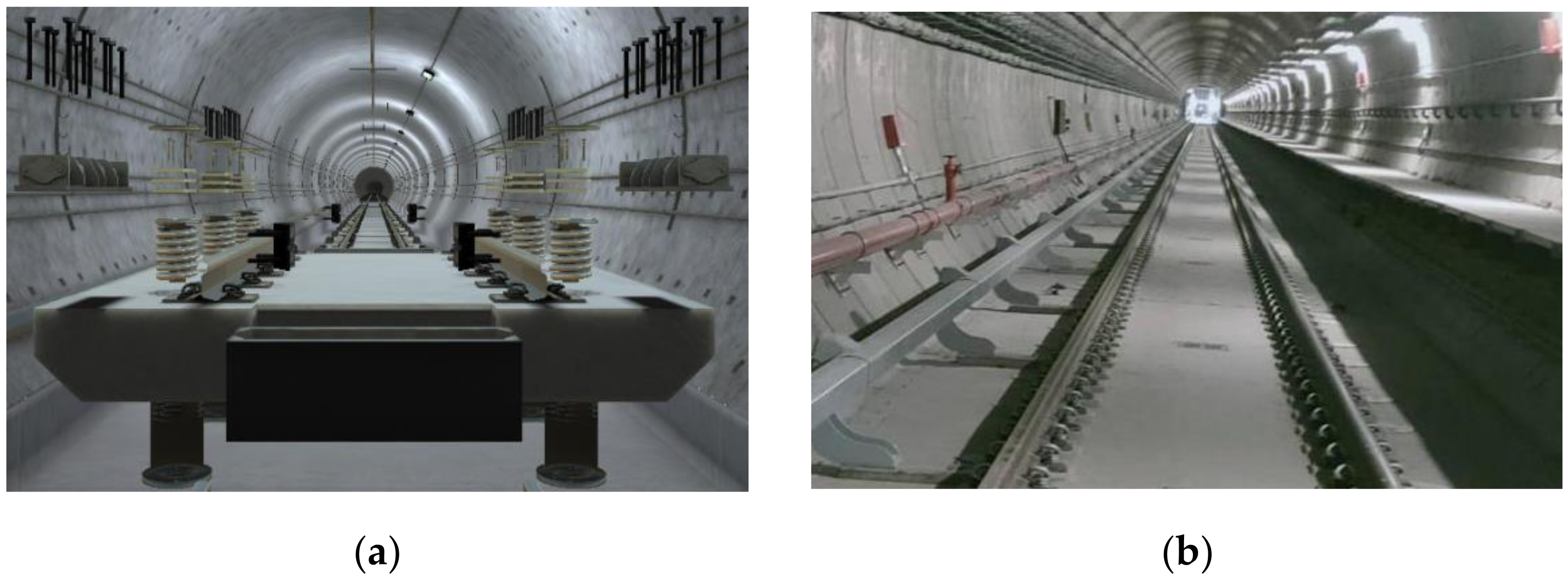
The structure split diagram of the steel-spring-floating slab track and the on-site diagram are shown in
Figure 3, the steel-spring-floating slab track has the following advantages:
(1) The geometric space of the tunnel can be used effectively [
16]. The lateral clearance between the track bed and the tunnel sidewall is small, which is beneficial to reduce the clearance of the tunnel, reduce the engineering cost, and increase the application range of the steel-spring-floating slab track.
(2) It is convenient to repair and replace the spring and does not affect the normal operation of the train.
(3) The floating slab part of the steel-spring-floating slab and the damping part of the steel spring consume energy, which can ultimately reduce the load from the track to the subgrade [
17,
18].
Under different line conditions, the vehicle-track-coupled vibration system may have different responses. Therefore, the ordinary monolithic track control group is used to compare the vibration of the steel-spring-floating slab track under different line conditions. The experimental method is the most reliable and real research method. Therefore, in order to study the vibration characteristics of the steel-spring-floating slab track under the actual train load, the steel-spring-floating slab track of a subway line and the ordinary monolithic track of the corresponding segment were selected for vibration testing. For this purpose, the accelerations of the rail, track bed, and tunnel walls of the steel spring floating slab track in the straight and curvilinear segments are compared and analyzed with those of the ordinary monolithic track, which could provide an experimental basis for the corresponding railway line vibration evaluation and related theoretical research.
Since the steel-spring-floating slab track is widely used in subway lines, it is necessary to analyze and study the vibration damping and transfer characteristics of the steel- spring-floating slab track in various frequency bands under the action of train loads. Therefore, the novelty of the work and study tasks are as follows:
Novelty of the work: (1) The difference of the vibration response of the steel-spring- floating slab track under different line conditions is studied, and the difference of the vibration of the steel-spring-floating slab track in the straight line and the curved section is clarified; (2) an ordinary monolithic track with similar line conditions is used as the control group to highlight the uniqueness of the vibration characteristics of the steel- spring-floating slab track; (3) the process response of vibration transmitted from the rail to the track bed of the steel-spring-floating slab track and finally to the tunnel wall is analyzed under train excitation; (4) a variety of signal processing methods in the field of mechanical engineering are introduced, and the laws of vibration attenuation and transmission of subway steel-spring-floating slab tracks are studied from various perspectives.
Study tasks: (1) The vibration test plan of the subway steel-spring-floating slab track and the general track bed is designed, the test sites of the straight line and the curved section are determined, and the test equipment and the position of the test point are selected. (2) Based on the acceleration data of the test, the time domain analysis and empirical mode decomposition are compared to show the change of the vibration process of the steel-spring-floating slab track with time. (3) The frequency spectrum of the steel- spring-floating slab track and the ordinary monolithic track is obtained, and the cross-spectral analysis method is used to determine the vibration frequency-domain correlation between the rail-track bed–tunnel wall in different frequency bands. (4) The method of vibration level analysis is used to compare and study the frequency division vibration level response of the track system and the track components, and the insertion loss of the steel-spring-floating slab track in the straight line and the curved section is calculated. (5) The vibration transfer between the rail-track bed–tunnel wall is studied, the frequency division vibration-level-transfer difference and transfer ratio are compared, and the transfer function method is introduced for further analysis. (6) According to the relevant industry specifications, the Z vibration levels of the rails, track beds, and tunnel walls were calculated and compared, so as to obtain the vibration reduction effect of the steel-spring-floating slab track under different line conditions.
2. Vibration Test Plan Design
2.1. Subway Line Condition
In this experimental study, one straight line segment and one curved test section were selected on the subway lines where the steel-spring-floating slab track and ordinary monolithic track were installed, respectively. In summary, a total of 4 test sections were subjected to vibration testing (
Table 1). Among them, “one thousandth” (‰) is used for the slope mark.
2.2. Measuring Point Arrangement
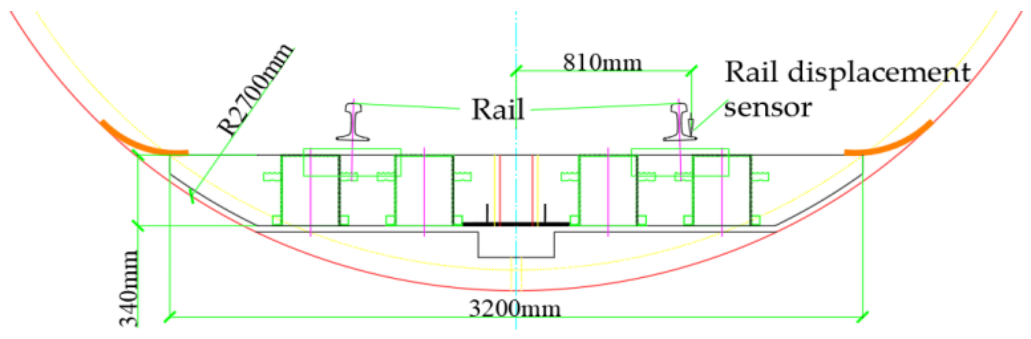
The displacement of the rail relative to the steel-spring-floating slab track is measured by a displacement sensor. Two displacement sensors per measuring segment are used to measure the vertical deformation of the rail relative to the track bed (
Figure 4). Through the vertical dynamic displacement curve of the rail, combined with the model parameters of the train, the operating speed of the train can be calculated and analyzed.
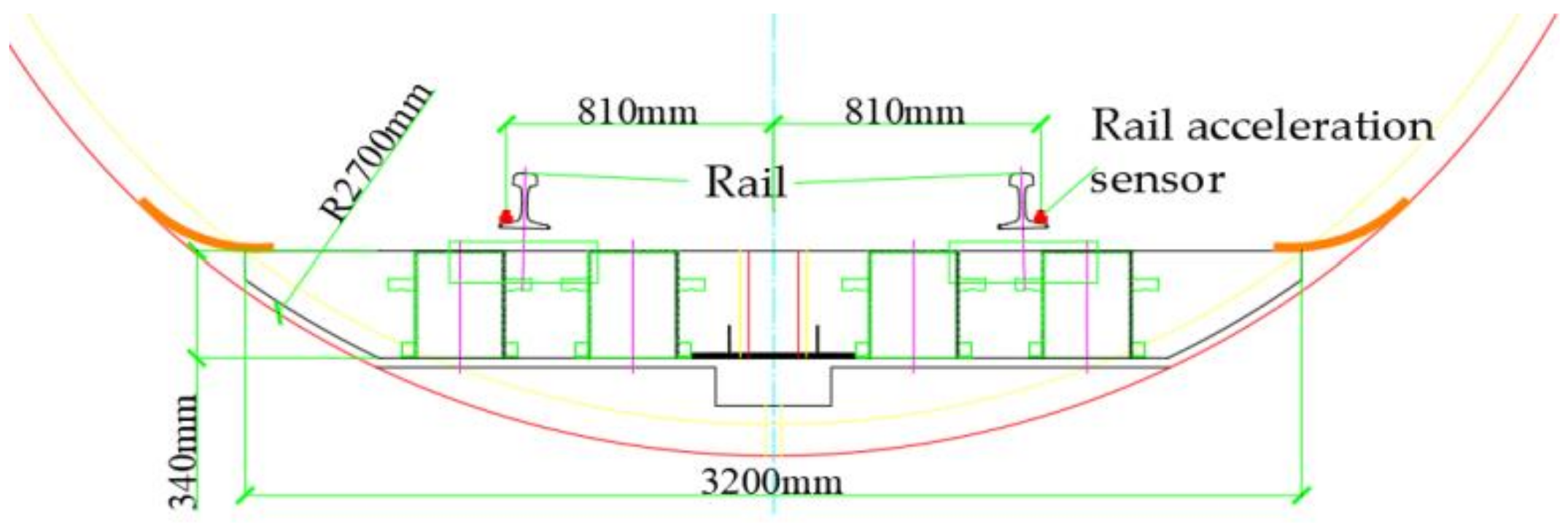
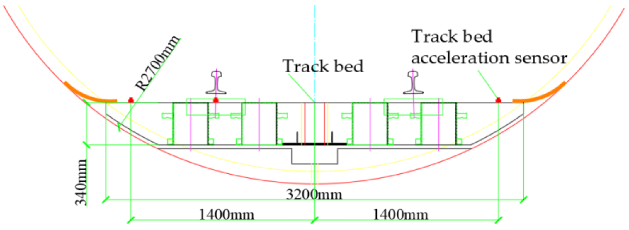
Vibrations of the track bed are measured by an acceleration sensor. Two acceleration sensors are used for each measurement segment, one is used to measure the vertical acceleration of the rail (
Figure 5), and the other is used to measure the vertical acceleration of the track bed (
Figure 6).
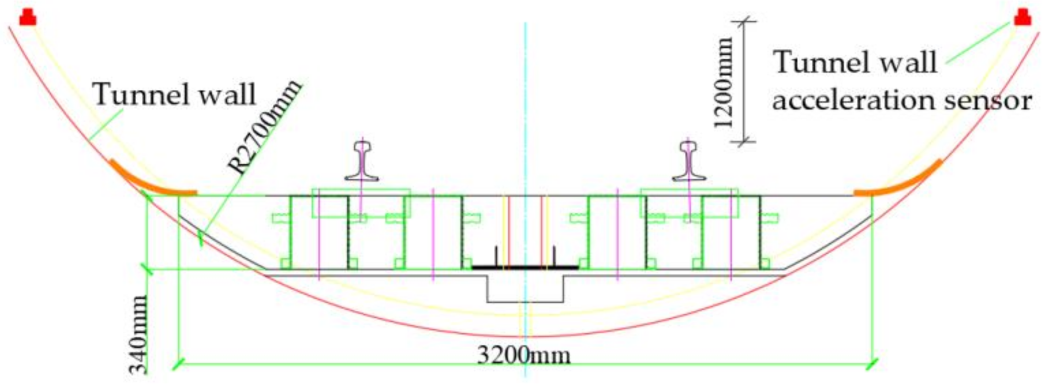
Vibrations of tunnel wall are measured by an acceleration sensor. Each measurement segment adopts an acceleration sensor to measure the vertical acceleration of the tunnel wall (
Figure 7).
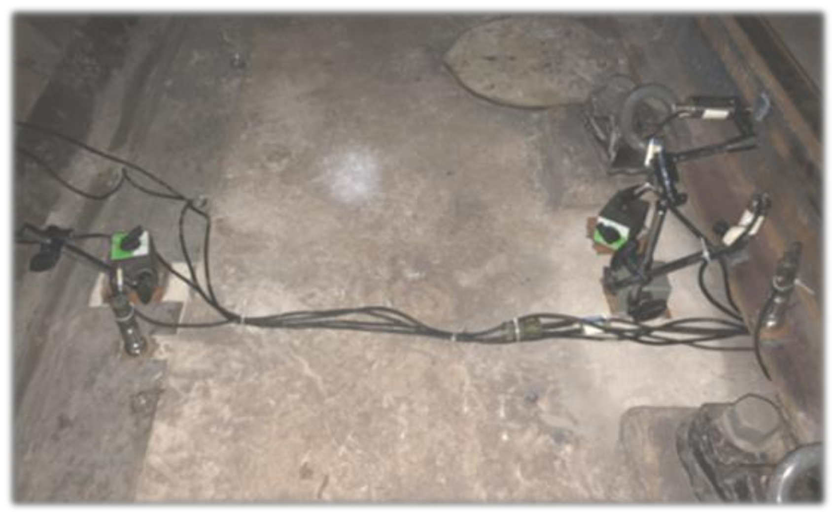
According to the above test plan, the time of the “train stops” is selected to arrange the displacement and acceleration sensors in the four working condition segments. The layout of on-site measuring points is shown in
Figure 8. For the range of the acceleration sensor, the rail acceleration adopts 2000 g acceleration sensors, the track bed acceleration adopts 25 g acceleration sensors, and the tunnel wall acceleration adopts 0.5 g acceleration sensors. The sensitivities of the three types of sensors are 5 Mv/g, 200 Mv/g, and 10,000 Mv/g, respectively; the resolutions are 8 mg, 0.2 mg, and 0.002 mg, respectively.
3. Test Data Analysis
3.1. Time Domain Analysis
3.1.1. Time-Domain Curve Analysis
During the test, the vibration of the environment around the tunnel will generate a certain amount of clutter, and the acceleration sensor at the tunnel wall has high accuracy, so it is very susceptible to the influence of small external vibrations. Therefore, in order to eliminate the influence of clutter on the experimental analysis, it is necessary to perform noise reduction processing on the collected signals. According to the analysis of the reference [
19], the wavelet threshold denoising has a good noise reduction effect on the vibration test data, so it is eliminated to reduce the noise in the test process.
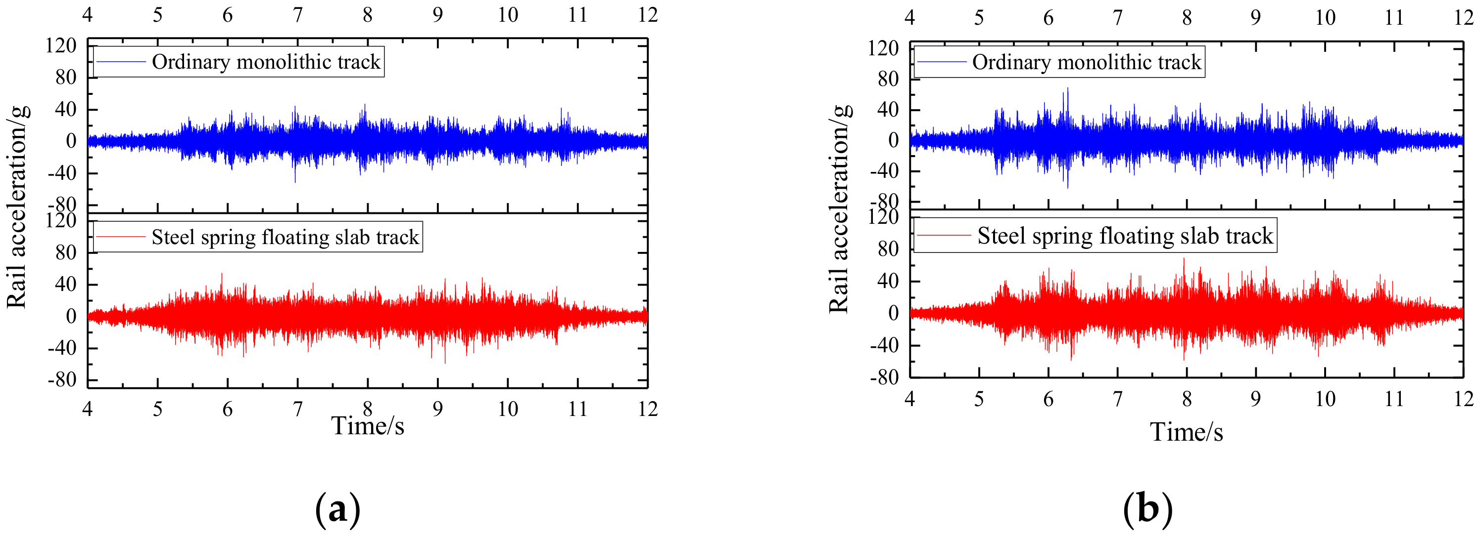
Based on the vibration test data after noise reduction, in order to compare and study the vibration characteristics of the steel-spring-floating slab track relative to the ordinary monolithic track under different line conditions, time-domain analysis of the accelerations of rail, track bed, and tunnel walls for the ordinary monolithic track and the steel-spring- floating slab track in straight and curved segments is shown in
Figure 9,
Figure 10 and
Figure 11, and it can be seen that:
(1) According to
Figure 9, for the acceleration of the rail, the acceleration of the steel- spring-floating slab track is similar to that of the ordinary monolithic track, and is slightly larger than that of the ordinary monolithic track, which shows that the four working conditions are very close at the excitation level of the rail, so the vibration isolation and transmission of the track bed and the tunnel wall can be well compared. The rail accelerations under different line conditions are very close, and the rail acceleration in the curved segment is greater than that in the straight line segment, indicating that the excitation of the rail in the curved segment is slightly greater than that in the straight line segment.
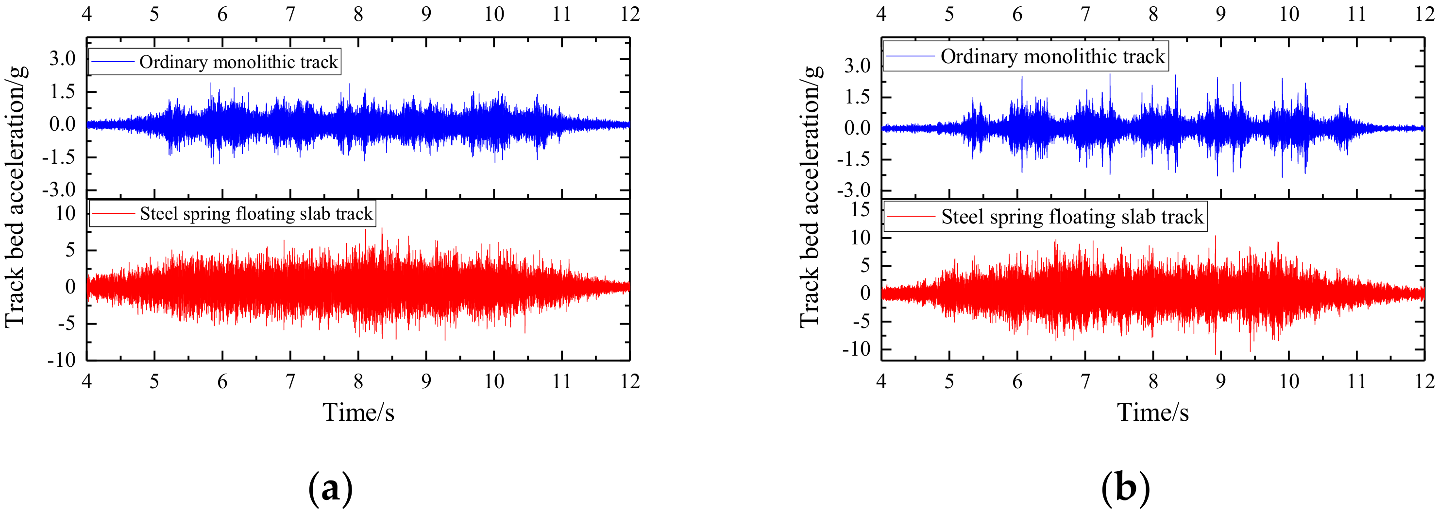
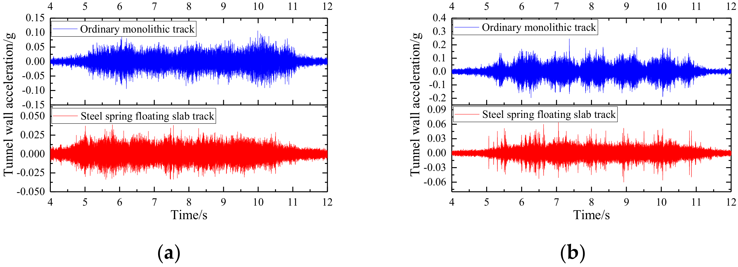
(2) According to
Figure 10, for the acceleration of the track bed, it can be seen that the acceleration of the steel-spring-floating slab track is significantly larger than that of the ordinary monolithic track, and its amplitude is about 3~4 times that of the ordinary monolithic track. The reason is that the bottom of the ordinary monolithic track is fully constrained, while the bottom of steel-spring-floating slab track is only constrained by vibration isolators and the overall stiffness is small, so the dynamic effect is more significant under similar excitation conditions. The acceleration of the track bed in the curved segment also shows a similar law, and is slightly larger than the acceleration of the track bed in the straight line segment.
(3) According to
Figure 11, for the tunnel wall acceleration, the steel-spring-floating slab track segment is significantly smaller than the ordinary monolithic track segment, and the amplitude is about 0.2~0.3 of the ordinary monolithic track. It can be seen that when the excitations at the rail are similar, the steel-spring-floating slab track has an excellent vibration isolation effect, which can filter and weaken the vibration very efficiently, which is of great significance to ensure the vibration damping requirements along the subway line.
3.1.2. Empirical Mode Decomposition Analysis
Empirical mode decomposition is an adaptive signal time-frequency processing method, which is more suitable for the processing of nonlinear and non-stationary signals. The essence is to decompose the noisy signal into each component intrinsic-mode function step by step, from high frequency to low frequency, based on the time scale [
20].
This method decomposes complex signals into a limited number of high-frequency and low-frequency components with meaningful instantaneous frequencies, whose frequency or amplitude can be modulated, and has the advantages of no prior knowledge and strong adaptability [
21,
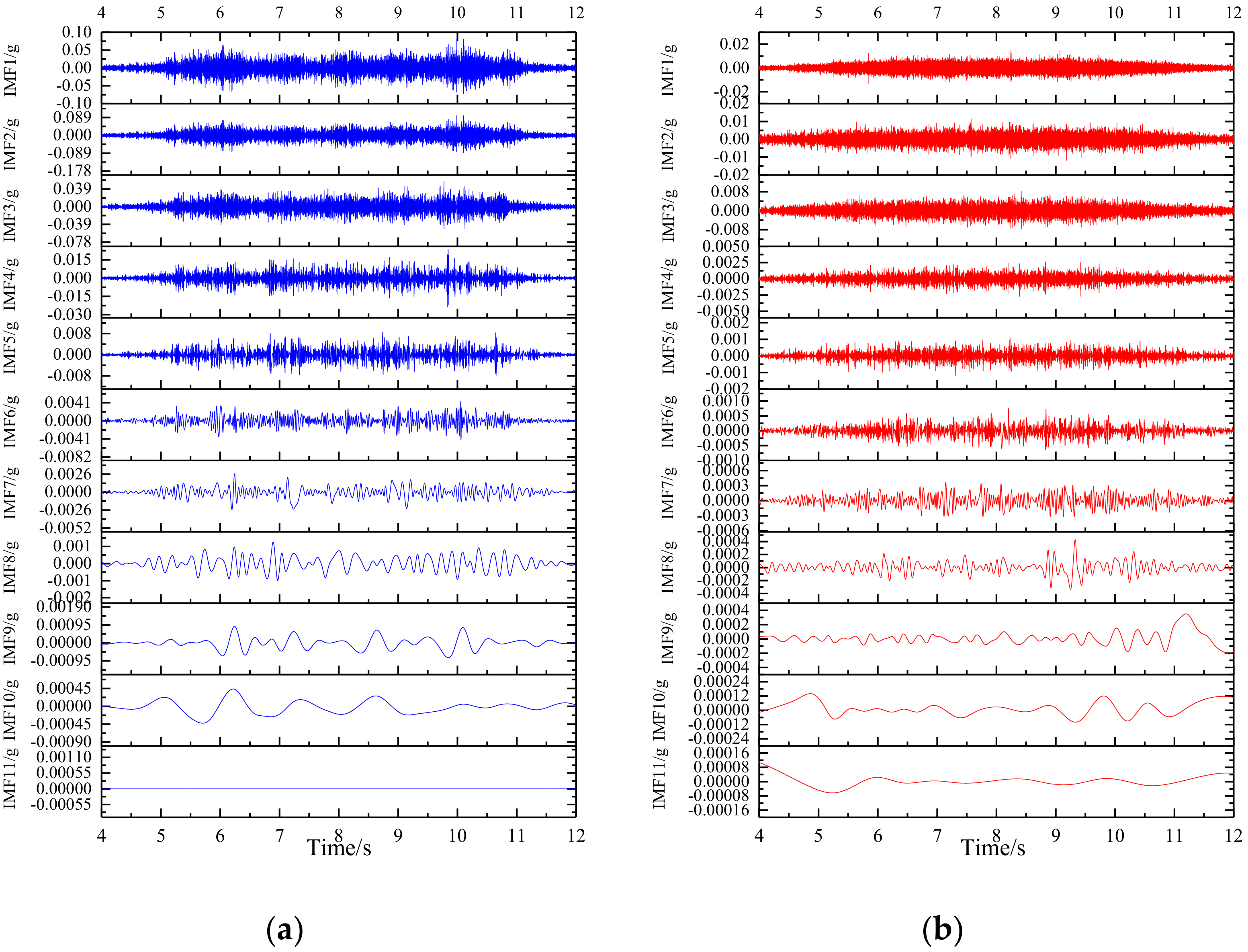
22]. Since the acceleration of the tunnel wall is the most concerned, the empirical mode decomposition method is used to decompose the acceleration time-domain curves of the tunnel wall under the four working conditions, as shown in
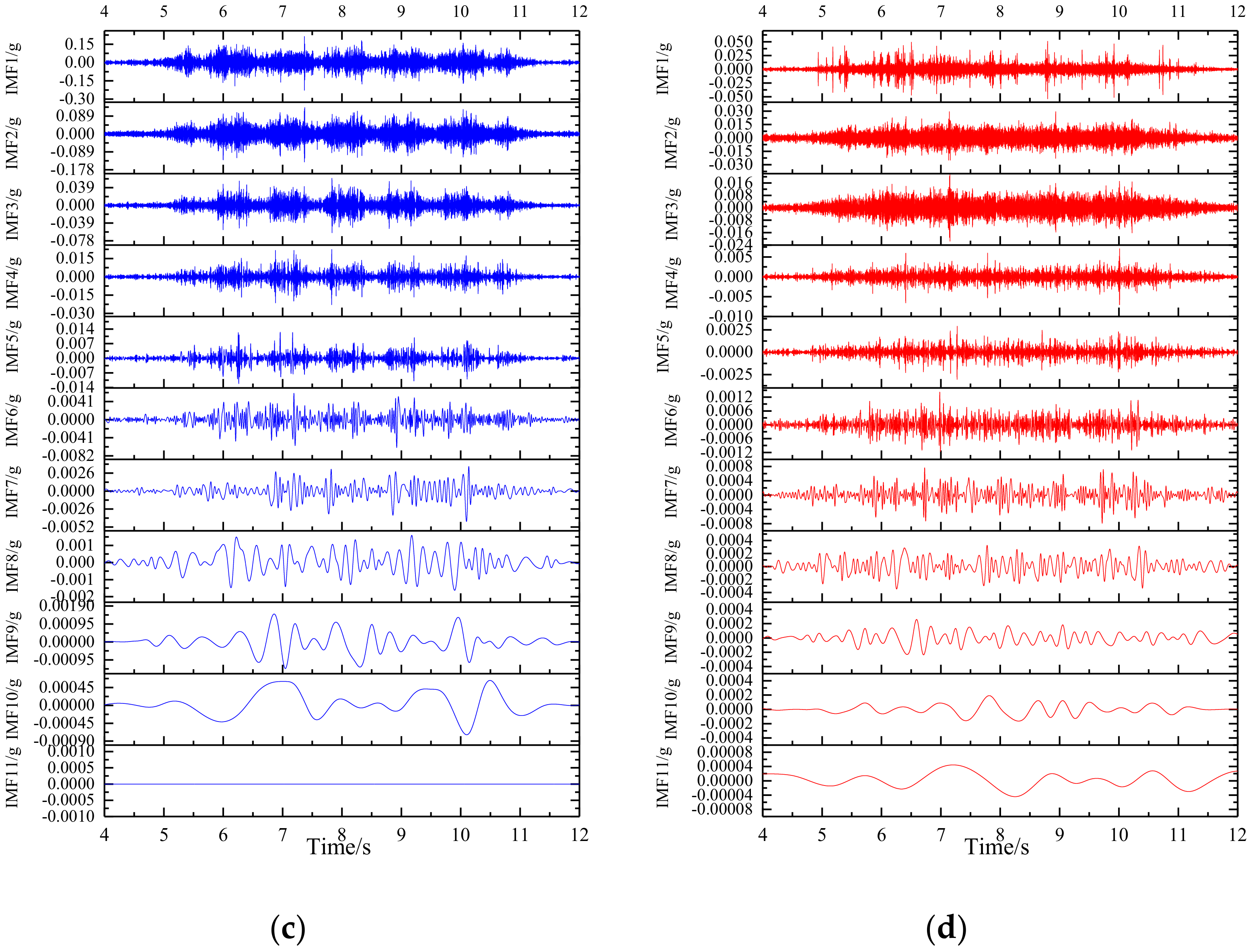
Figure 12, among them, IMF1~11 refers to the intrinsic mode function of the 1st~11th order. It can be seen that the acceleration time-domain curves of the tunnel wall under the four working conditions can be decomposed into 11 orders, and each order intrinsic-mode function of the tunnel wall at steel-spring-floating slab track vibration is smaller than the corresponding intrinsic-mode function curve of the ordinary monolithic track tunnel wall vibration. Therefore, the steel-spring vibration isolator has a weakening effect on the vibration in all frequency bands.
Comparing
Figure 12a,c, it can be seen that there are 6 peak envelopes on the decomposed intrinsic-mode function curve for the ordinary monolithic-track tunnel wall acceleration, corresponding to the 6 carriages of the B-type subway car, and the peak envelope of the curved segment is more obvious. Except for intrinsic mode function 3, intrinsic mode function 4, intrinsic mode function 5, and intrinsic mode function 11, the intrinsic- mode function amplitudes of other orders in the curved segment are significantly larger than those in the straight line segment, especially intrinsic mode function 1. It can be seen that the amplitude of the high-frequency signal in the curved segment increases significantly.
Comparing
Figure 12b,d, it can be seen that the intrinsic mode function 2, intrinsic mode function 3, intrinsic mode function 5, intrinsic mode function 10 of the tunnel wall at the steel-spring-floating slab track acceleration in the curved segment have increased, especially in the intrinsic mode function 2 and intrinsic mode function 10. It can be seen that the high-frequency and low-frequency signal intensities in the curved segment have increased.
3.2. Frequency Domain Analysis
3.2.1. FFT Analysis
Time domain analysis can only describe the change of signal amplitude with time, while the frequency domain analysis allows us to more intuitively understand the composition of the signal as it reflects the essence of the signal [
23]. Therefore, it is necessary to use the FFT method to transform the above vibration time domain signal, and plot the magnitude (RMS) spectrum, where the RMS value is the “Root mean square” of the signal and is used to characterize the amount of energy in the signal [
24]. For calculating the RMS value from the time domain, the sum of the squares of all the amplitudes of the time series should be calculated, then divided by the total number of sample points, and, finally, the square root should be taken [
25,
26]. The above method is adopted to draw the vibration signal amplitude (RMS) spectrum, as shown in
Figure 13,
Figure 14 and
Figure 15.
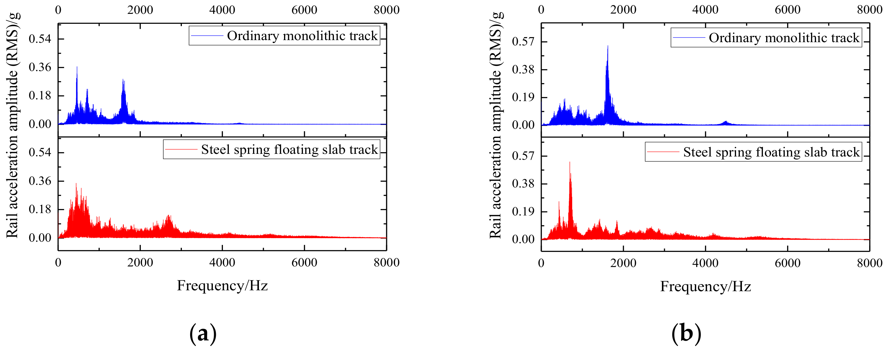
(1) According to
Figure 13a, it can be seen that the rail acceleration spectrum distribution of the ordinary monolithic track and the steel-spring-floating slab track is significantly different. The peak points of the rail acceleration spectrum of the ordinary monolithic track are concentrated in the segment below 2000 Hz, and there are obvious peak points at 458.73 Hz and 1617.98 Hz. The amplitudes are 0.32 g and 0.28 g, respectively. The spectral peak points of the steel-spring-floating slab track are distributed in 0~3000 Hz, and the peak point density below 1000 Hz is greater than the rail acceleration of the ordinary monolithic track. Its two obvious peak points are located at 438.96 Hz and 2683.52 Hz, and their amplitudes are 0.35 g and 0.15 g, respectively. For the curved segment, as shown in
Figure 13b, it can be seen that the amplitudes of each peak point are significantly larger than those of the straight-line segment. The maximum values of the ordinary monolithic track and the steel-spring-floating slab track are located at 1622.26 Hz and 693.99 Hz, respectively, and the amplitudes are 0.55 Hz and 0.53 Hz, respectively.
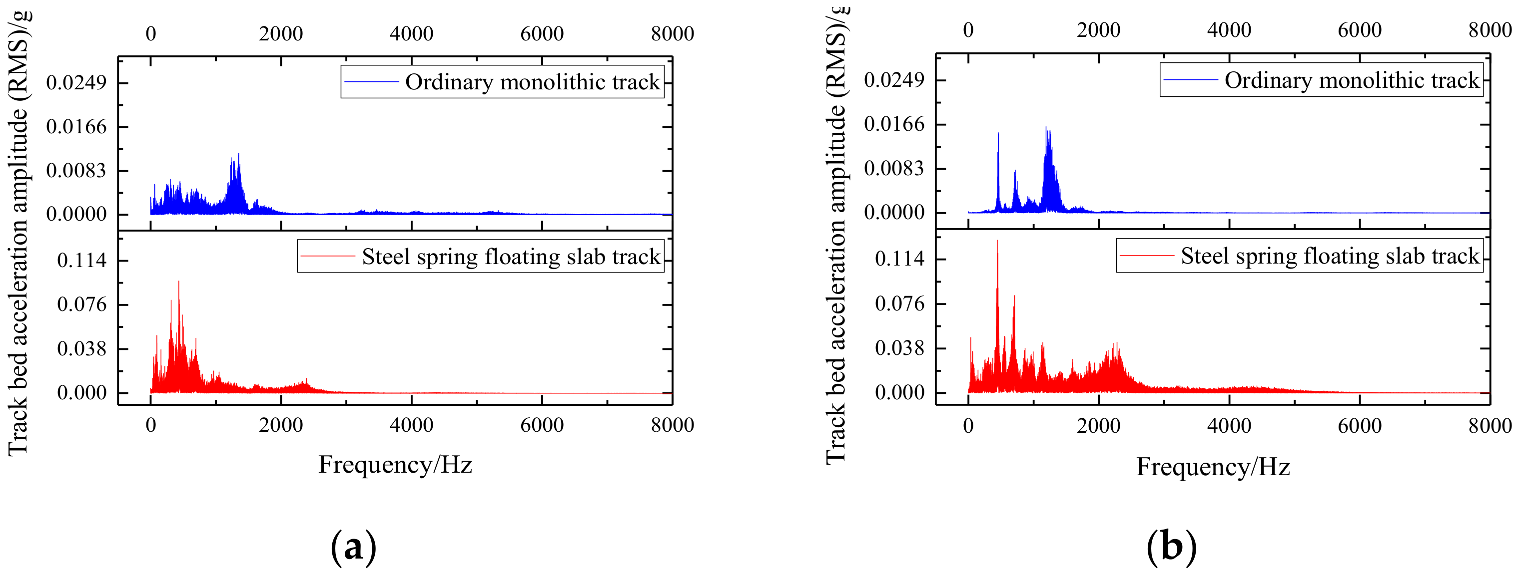
(2) Comparing the waveform diagrams in
Figure 13 and
Figure 14, it can be seen that the vibration acceleration waveform of the track bed is consistent with the waveform of the rail, where the position of the peak point is the same as the shape change law of the waveform, indicating that the transmission efficiency of the fastener for each frequency band of the rail acceleration is similar. However, the amplitude of the waveform of the steel- spring-floating slab track is significantly larger than that of the ordinary monolithic track. The reason is that the bottom of the steel-spring-floating slab track is suspended, and its constraints are less, and the stiffness of the vibration isolator is also maintained at a smaller value, with the result that the acceleration of the track bed of the steel-spring-floating slab track is significantly greater than that of the ordinary monolithic track. In
Figure 14a, the maximum peak values of the acceleration amplitudes of the track bed of the ordinary monolithic track and the steel-spring-floating slab track are located at 1290.93 Hz and 432.79 Hz, respectively, and their amplitudes are 0.012 g and 0.097 g, respectively. In
Figure 14b, the maximum peak values of the acceleration amplitudes of the track bed of the ordinary monolithic track and the steel-spring-floating slab track are located at 1249.33 Hz and 442.39 Hz, respectively, and their amplitudes are 0.015 g and 0.131 g, respectively. It can be seen that the peak positions of the acceleration spectrum of the track bed under different line conditions are very close, but the amplitude of the curved segment is larger than that of the straight line segment.
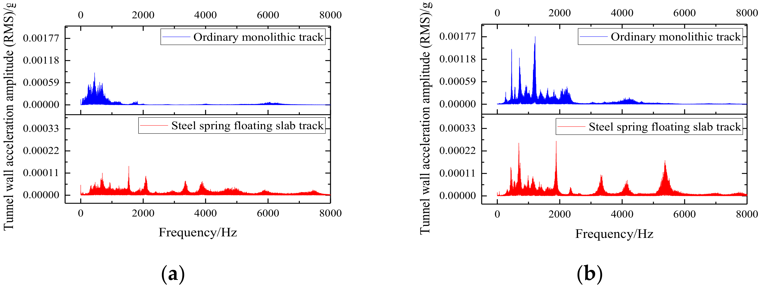
(3) Since the acceleration amplitude of the tunnel wall reflects the impact of train vibration on the environment, it is also the key to evaluating the vibration damping effect of the track structure. According to
Figure 15, the peaks of the acceleration amplitude spectrum of the tunnel wall in the tunnel wall at the steel-spring-floating slab track segment are significantly smaller than those in the ordinary monolithic track segment, especially the frequency band below 2500 Hz is greatly weakened. In
Figure 15a, the maximum peak values of the tunnel wall acceleration amplitudes of the ordinary monolithic track and the steel-spring-floating slab track are located at 442.86 Hz and 1541.73 Hz, respectively, and their amplitudes are 8.57 × 10
−4 g and 1.44 × 10
−4 g, respectively. In
Figure 15b, the maximum peak values of the tunnel-wall acceleration amplitudes of the ordinary monolithic track and the steel-spring-floating slab track are located at 1213.73 Hz and 1888.33 Hz, respectively, and their amplitudes are 1.7 × 10
−3 g and 3.21 × 10
−4 g, respectively. It can be seen that the vibration isolator of the steel-spring-floating slab track can effectively isolate and filter the frequency band below 2500 Hz, and its built-in damping structure can greatly consume the vibration energy, thereby reducing the vibration wave transmitted to the tunnel wall.
3.2.2. Cross-Spectral Analysis
Cross-power spectrum, abbreviation for cross-power density spectrum, is a method to describe the degree of statistical correlation between two different signals in the frequency domain [
27]. There are two stationary random signals x(t) and y(t), according to stochastic process theory, the statistical correlation between them should be expressed by their cross-correlation function. Fourier transform is performed on the cross-correlation function of x(t) and y(t) to obtain the power density spectrum in the frequency domain, which is called the cross-power density spectrum, also known as the cross-spectrum. The cross-spectrum and the cross-correlation function are two different representations that describe the statistical correlation of two signals from the frequency domain and the time domain, and they are mutual Fourier transforms and are suitable for deterministic signal analysis. Therefore, it is useful to measure the input and output signals of the system, and perform the cross-spectral operation between the two.
The
and
self-spectra
and
can be obtained by the Welch average periodogram method; then, the amplitude squares of
and
are coherent functions [
28] (referred to as the coherence function) and are given by:
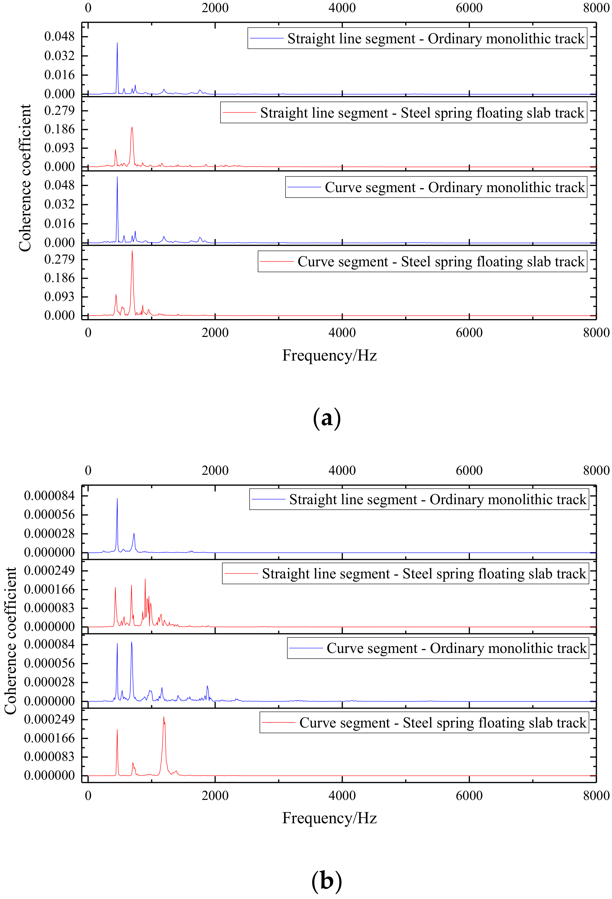
The coherence function can measure the degree of correlation between two signals in the frequency domain. The frequency band with a large coherence function contains more source signal components, and the signal-to-noise ratio of the frequency band is higher. Therefore, the coherence function and cross-power spectral-difference spectrum of the collected vibration signals of the rail, track bed, and tunnel wall can be used to estimate the characteristic frequency band of the source signal, so that the vibration correlation between different track components can be analyzed (
Figure 16).
According to
Figure 16a, it can be seen that the coherence coefficient of the rail–track bed acceleration spectrum of the steel-spring-floating slab track is significantly larger than that of the ordinary monolithic track. The rail–track bed acceleration spectral coherence curve of the ordinary monolithic track has one significant peak point at 458 Hz; the steel-spring-floating slab track has two significant peak points at 429 Hz and 693 Hz, respectively. Compared with the straight line segment, the coherence coefficient amplitude of the curved segment is larger, and there are more fluctuation points at high frequencies.
According to
Figure 16b, it can be seen that the coherence curves of the track bed–tunnel wall acceleration spectrum under the four working conditions are quite different. The track bed–tunnel wall acceleration spectral coherence curve of the ordinary monolithic track has 2 significant peak points (458 Hz, 683 Hz) in the straight line segment, and the amplitude of the peak point at 683 Hz in the curved segment increases. There are two additional peak points (967 Hz, 1162 Hz, 1875 Hz). The coherence coefficient of the track bed–tunnel wall acceleration spectrum of the steel-spring-floating slab track is significantly smaller than that of the ordinary monolithic track, and its characteristic frequency bands are located at 429 Hz, 684 Hz, and 898 Hz. The characteristic frequency bands of the curved segment have changed, and are located at 459 Hz, 703 Hz, and 1191 Hz, respectively.
3.3. Frequency-Division Vibration Level Analysis
According to the above analysis, the rail vibration of the steel-spring-floating slab track is similar to that of the ordinary monolithic track, the vibration of the steel-spring- floating slab track track bed is significantly larger, and the vibration of tunnel wall at the steel-spring-floating slab track is significantly smaller than that of the ordinary monolithic track. However, whether it is time-domain or frequency-domain analysis, from the calculated curves, it is difficult to judge the vibration of each frequency band in a standard way. Moreover, the amplitudes between the rail, the track bed, and the tunnel walls are all too different, making it inconvenient to perform quantitative vibration level comparison. Therefore, it is necessary to introduce the 1/3-octave frequency band to analyze the acceleration frequency-division vibration levels of the rail, track bed, and tunnel walls of the ordinary monolithic track and the steel-spring-floating slab track, so as to further reveal the vibration damping characteristics of the steel-spring-floating slab track [
29].
3.3.1. Track System Comparison
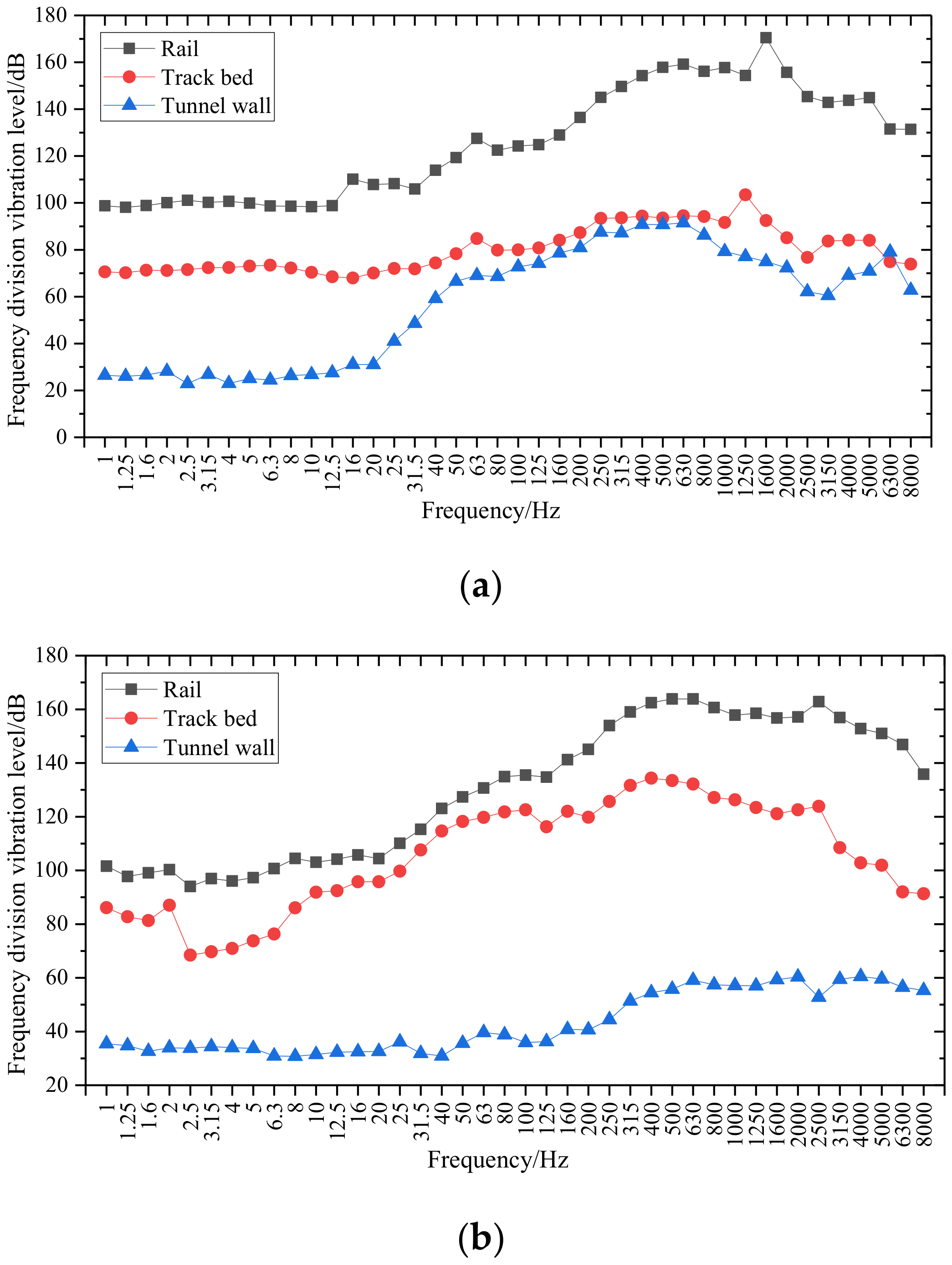
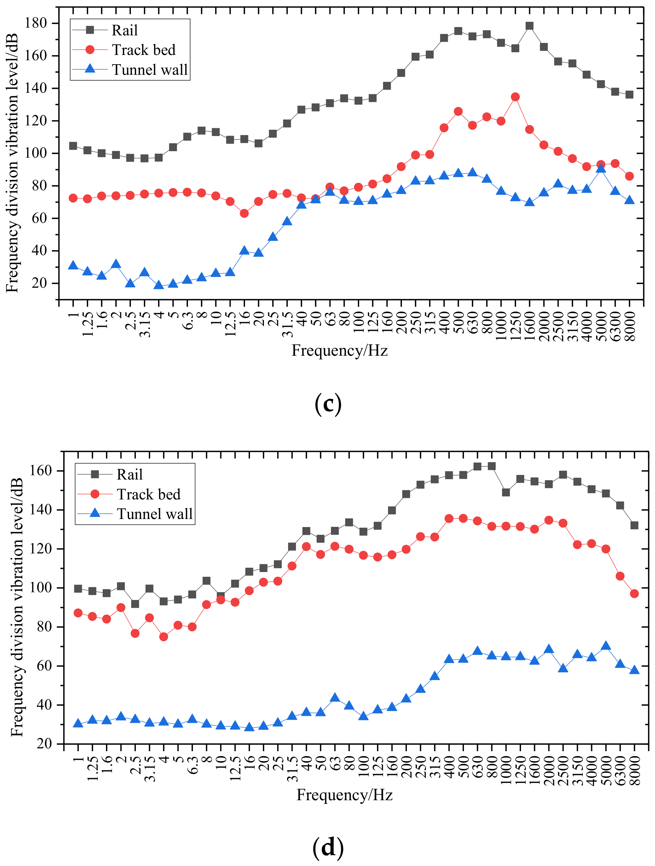
The 1/3-octave frequency analysis was carried out on the vibration acceleration of the rail, track bed and tunnel wall under the four test conditions, and the acceleration level in the range of 1~8000 Hz was obtained. The 1/3-octave acceleration levels of the rail, track bed, and tunnel walls in each working condition are compared. As shown in
Figure 17, it can be seen that with the vibration transmission of the rail, the track bed, and the tunnel wall, the sub-frequency vibration level of each frequency band decreases in turn.
According to
Figure 17a,c, it can be seen that the frequency-division vibration level curve of rail acceleration of the ordinary monolithic track is far away from the frequency-division vibration level curve of the track bed acceleration. The distance between the frequency-division vibration level curve of the acceleration of the track bed and that of the tunnel wall acceleration is relatively close, and the vibration level attenuation in the high- frequency band is small. In the frequency band above 50 Hz, the frequency-division vibration level curve of ordinary monolithic track is relatively close, indicating that this frequency band is the main segment where ordinary monolithic track vibration transmission occurs. It can be seen that the ordinary monolithic track is particularly poor for vibration isolation in frequency bands above 50 Hz. At the same time, the high-frequency vibration effect of rail, track bed, and tunnel walls in the curved segment is more significant, and there are multiple peak points.
According to
Figure 17b,d, it can be seen that the distance between the rail acceleration frequency division vibration level curve of the steel-spring-floating slab track and the track bed acceleration frequency-division vibration level curve is relatively close. The distance between the frequency-division vibration level curve of the acceleration of the track bed and the vibration level of the tunnel wall acceleration is far away, and the vibration level attenuation effect of each frequency band, especially the high-frequency band, is larger.
3.3.2. Track Parts Comparison
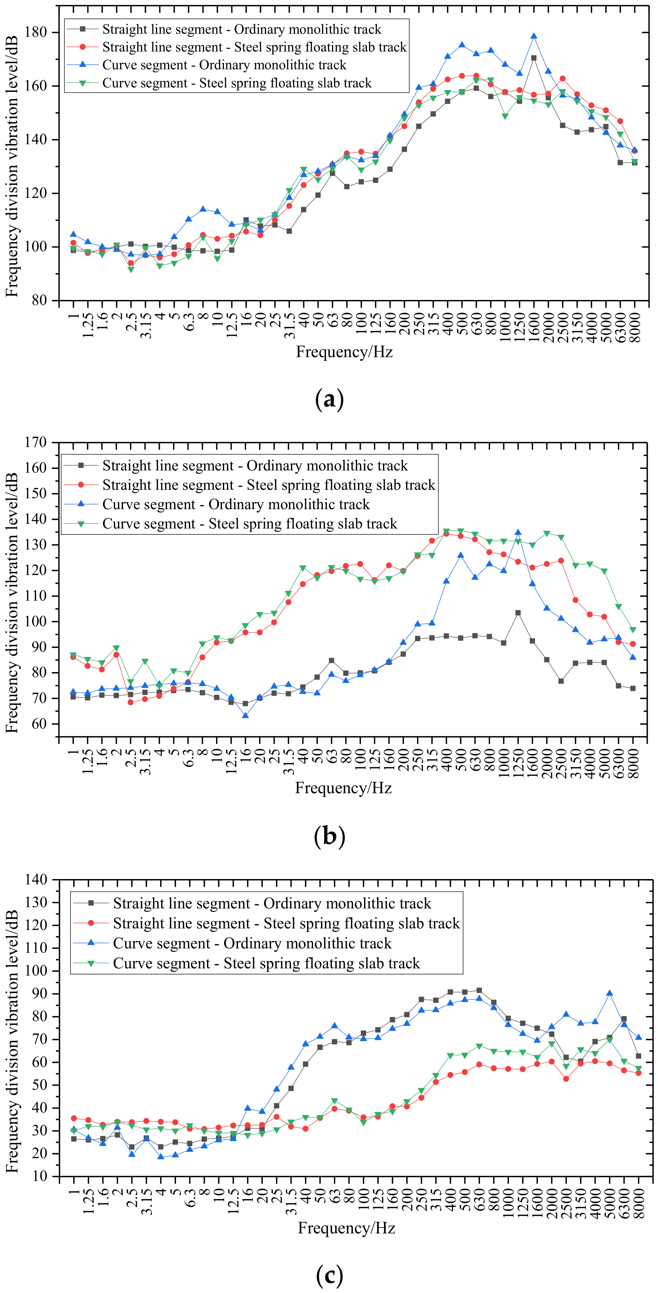
According to the analysis in
Section 3.3.1, the frequency-division vibration levels of rail, track bed, and tunnel walls will be different under different working conditions. Therefore, the frequency-division vibration levels of the rail components under each working condition are compared, as shown in
Figure 18. Under the working conditions of the same track type, the distance between the frequency-division vibration level curves of the straight line and the curved segment is relatively close. Each frequency band of the cross-frequency vibration-level curve in the curved segment is slightly larger than the straight line segment, and the difference is significant in the high-frequency band.
According to
Figure 18a, although the restraint conditions at the bottom of the track bed are different, the vibration level curves of the rail under the four working conditions are very close, and the vibration level curve basically shows the phenomenon that the vibration level of high frequency is larger. The peak point of ordinary monolithic track appears at 1600 Hz, while the peak point of the steel-spring-floating slab track is located at 2500 Hz, and the shape of the rail frequency-division vibration level curve of the same track structure is basically the same.
According to
Figure 18b, it can be seen that in most of the segments (especially above 6.3 Hz), the frequency-division vibration level curve of the steel-spring-floating slab track is larger than that of the ordinary monolithic track, and the vibration level of the high-frequency band in the curved segment is significantly larger than that in the straight line segment. Under the influence of line conditions, the frequency-division vibration-level curve of the ordinary monolithic track for frequencies above 315 Hz has multiple peak points, which are significantly larger than those of the straight line segment ordinary monolithic track. It even exceeds the steel-spring-floating slab track at 1250 Hz, indicating that the vibration of the ordinary monolithic track is more susceptible to line conditions.
According to
Figure 18c, it can be seen that the sub-frequency vibration level of the tunnel wall at the steel-spring-floating slab track acceleration is significantly smaller than that of the ordinary monolithic track in most frequency bands. However, in the low-frequency range below 16 Hz, the frequency-division vibration level of the steel-spring-floating slab track is larger than that of ordinary monolithic track, and the frequency-division vibration level of the ordinary monolithic track above 2000 Hz is slightly larger than that of the steel-spring-floating slab track. It can be seen that the vibration damping effect of the steel-spring-floating slab track is mainly reflected in the range of 16~2000 Hz.
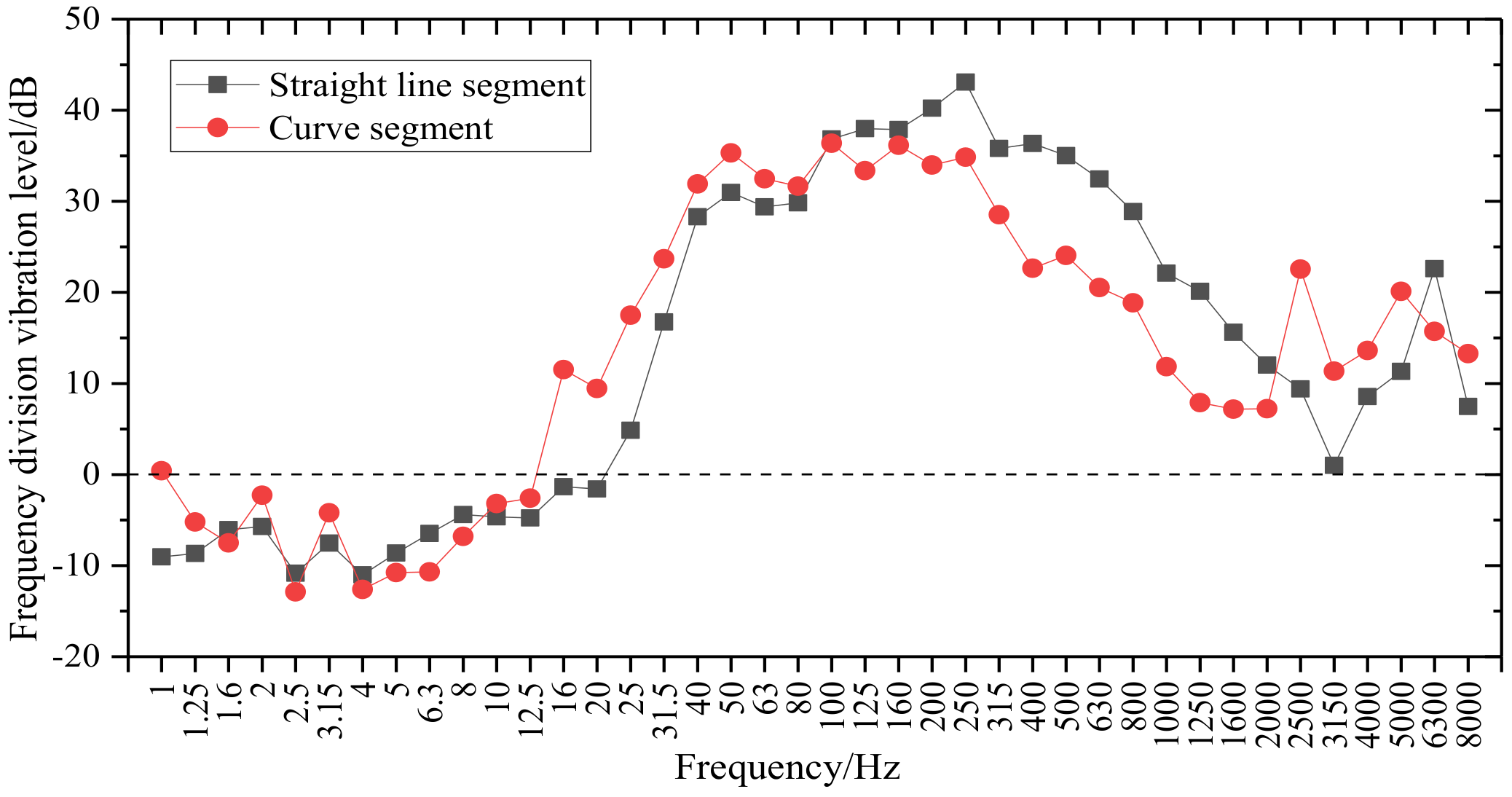
3.3.3. Insertion Loss Comparison
According to CJJ191-2012 “Technical Specification for Floating Slab Track” [
30], the vibration damping effect of the steel-spring-floating slab track is mainly evaluated by comparison with the ordinary monolithic track. For the insertion loss analysis of the sub-frequency vibration level, Δ
La obtained by subtracting the sub-frequency vibration level of the ordinary monolithic track tunnel wall and the sub-frequency vibration level of the tunnel wall at the steel-spring-floating slab track in the corresponding frequency band under each line condition is mainly used as the evaluation index. Taking the maximum difference Δ
Lmax of the frequency division vibration level as a reference, it is calculated according to the following formula [
30]:
In the formula:
VLq(i)—select the segment where the steel-spring-floating slab track is not adopted as the reference object, and the vertical vibration acceleration of the tunnel wall measuring point is the frequency-division vibration level (dB) of the i-th center frequency in the 1/3- octave band; in this research, the ordinary monolithic track tunnel wall acceleration measurement point was selected;
VLh(i)—the sub-frequency vibration level (dB) of the vertical vibration acceleration of the tunnel wall measuring point at the i-th center frequency of the 1/3-octave band in the segment where the steel-spring-floating slab track is taken.
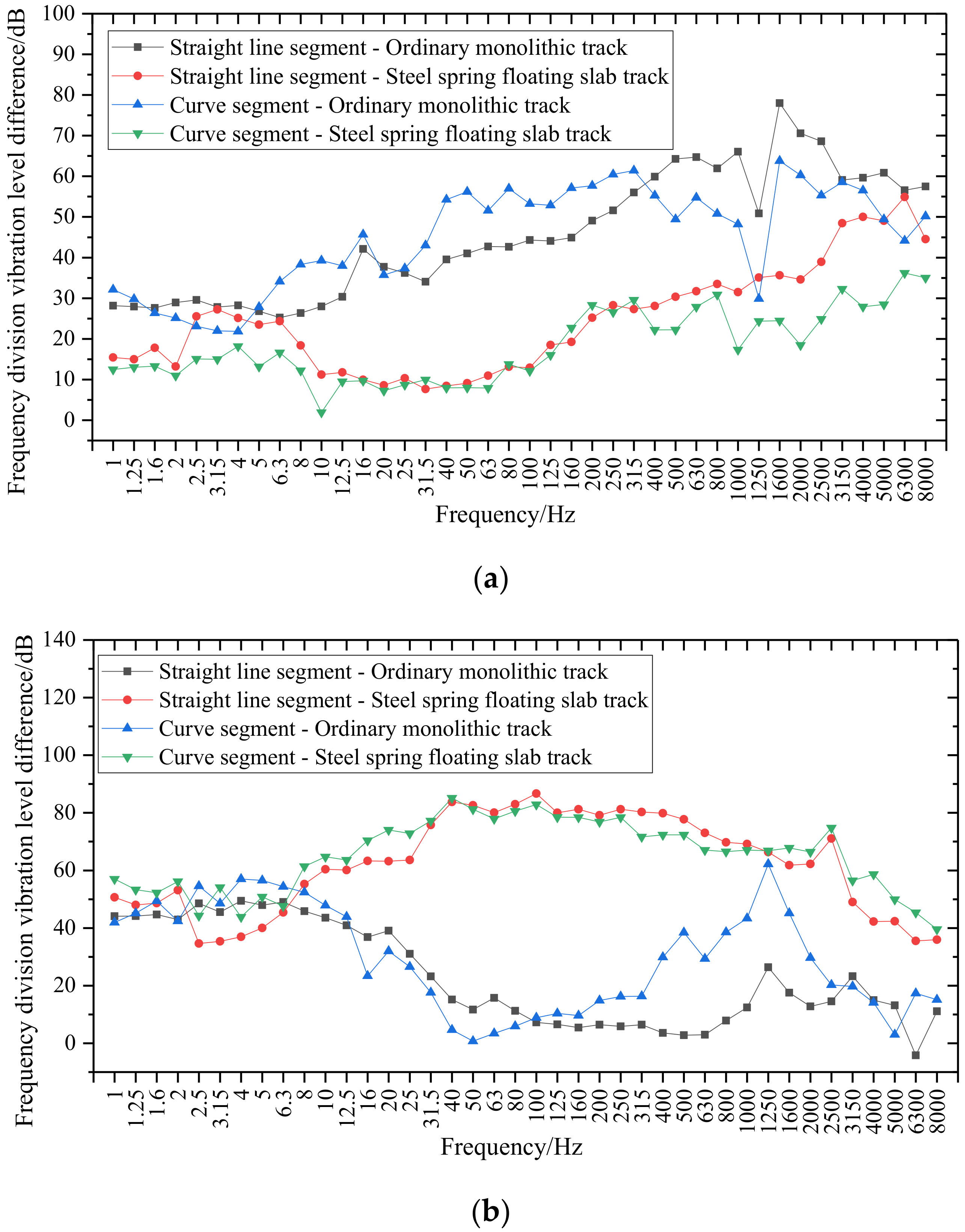
Therefore, the steel-spring-floating slab track frequency-division vibration level-insertion loss curve of the straight line and the curved segment is obtained, as shown in
Figure 19. By comparing the frequency-division vibration level insertion loss curves of the straight line and the curved segment, it can be seen that the steel-spring-floating slab track insertion loss curve of the straight line and the curved segment is similar, and the insertion loss of the curved segment at high frequencies is greater than that of the straight line segment. The reason is that the high-frequency vibration response of the ordinary monolithic track tunnel wall in the curved segment is intensified, and the vibration damping effect is achieved by using the steel-spring-floating slab track.
3.4. Frequency Response Transfer Analysis
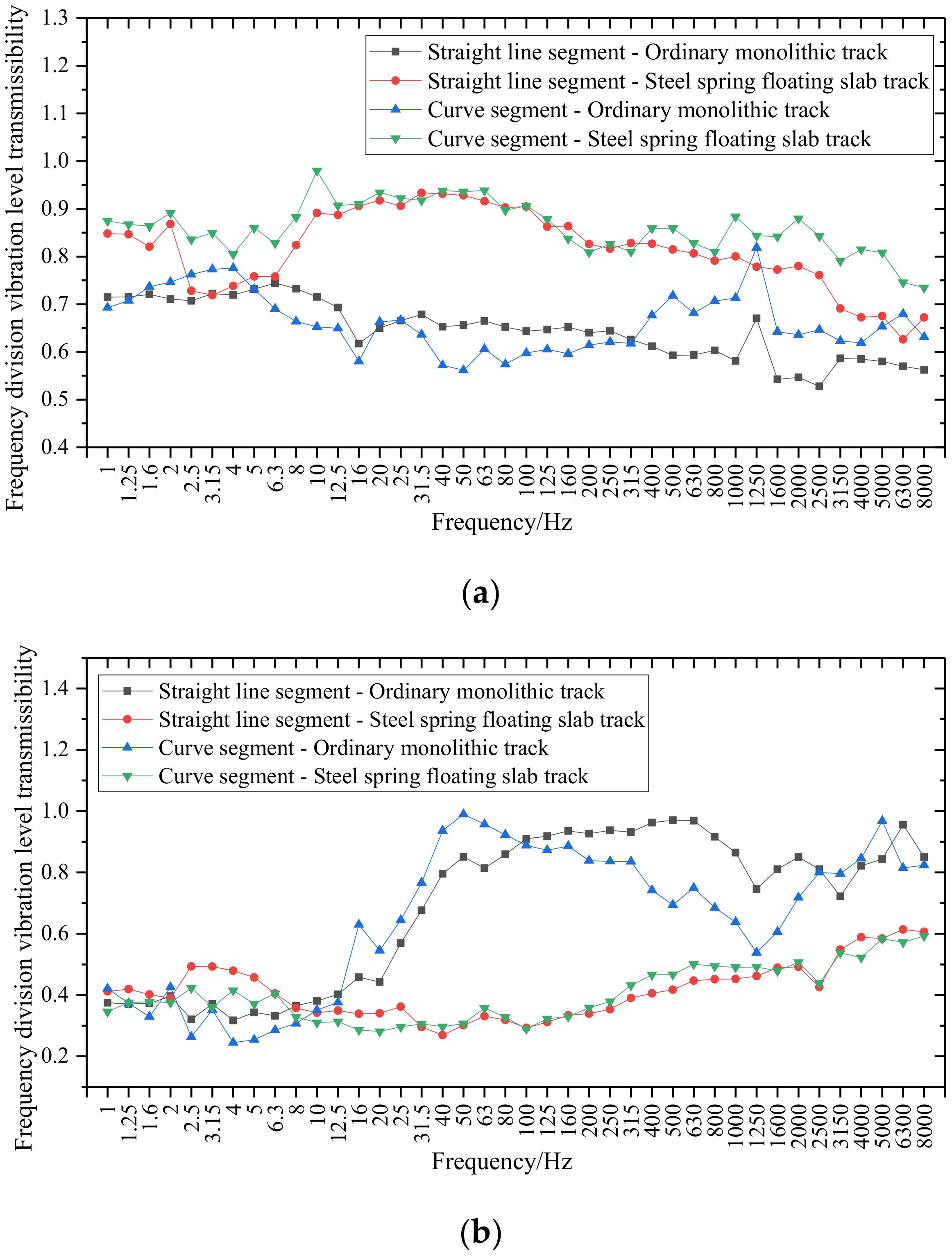
3.4.1. Vibration-Level Transfer Analysis
In order to analyze the frequency-division vibration-level transfer characteristics of the rail, the track bed and the tunnel wall under the four working conditions, the vibration-level transfer difference and the vibration-level transfer rate of the rail–track bed, track bed and tunnel wall are compared and analyzed, as shown in
Figure 20 and
Figure 21. Among them, the vibration-level transfer difference is the difference between the frequency-division vibration levels of each frequency band of the rail–track bed, track bed–tunnel wall, and the vibration-level transfer rate is the frequency-division vibration-level ratio of the track bed–rail, tunnel wall–track bed. It can be seen that the vibration-level transmission difference is inversely proportional to the transfer rate, that is, if the vibration-level transmission difference between adjacent track components is larger, the transfer rate is correspondingly smaller.
According to
Figure 20a and
Figure 21a, it can be seen that for the vibration-level transfer between the rail and the track bed, the vibration-level reduction of the steel-spring-floating slab track is small, that is, the vibration-level transfer rate is large. Especially in the vibration level in the 12.5~100 Hz frequency band, the vibration-level transfer rate is generally around 0.9. However, the rail–track bed vibration-level transfer difference of the ordinary monolithic track is generally larger than that of the steel-spring-floating slab track, and the vibration-level transfer rate of each frequency band is mostly between 0.6 and 0.75, and the vibration-level transfer rate gradually decreases as the frequency increases. At the same time, through the comparison between the straight line segment and the curved segment, it can be seen that for the frequency band above 400 Hz, the vibration transmission of the rail–track bed in the curved segment is significantly greater than that in the straight line segment.
According to
Figure 20b and
Figure 21b, it can be seen that for the vibration-level transfer between the track bed and the tunnel wall, the vibration level of the steel-spring-floating slab track is greatly reduced, that is, the vibration-level transmission rate is low, and the vibration level of each frequency band has dropped significantly. However, the vibration- level transfer difference between the track bed and the tunnel wall of the ordinary monolithic track is generally smaller than that of the steel-spring-floating slab track. In the frequency above 10 Hz, the vibration-level transfer rate is larger. The reason is that the ordinary monolithic track and the shield tunnel are consolidated by reinforced concrete, so the vibration transmission is equivalent to a whole structure, so the vibration level reduction is small and the vibration-level transmission rate is large. At the same time, it can be seen from the comparison between the straight line segment and the curved segment that the vibration-level transfer rate of the steel-spring-floating slab track in the segment below 10 Hz is greater than that of the ordinary monolithic track. The vibration-level transfer rate of the steel-spring-floating slab track in each frequency band of the straight line and the curved segment is very close, while the vibration level transmission of the ordinary monolithic track at high frequencies is smaller than that of the straight line segment.
3.4.2. Transfer Function Analysis
In actual engineering prediction, because the force between different subsystems is usually difficult to measure, and the vibration response
R,
R2.
Rn of each subsystem is easy to measure. Therefore, the concept of response transfer ratio needs to be introduced, which is defined as the ratio of the vibration responses of different subsystems under the excitation of the same vibration source load in the frequency domain [
31]. The definition formula is shown in Formula (5):
where
represents the frequency-domain vibration response of the mth subsystem,
represents the frequency vibration response of the
nth subsystem,
is the response transfer ratio of the
m-th and
n-th subsystems.
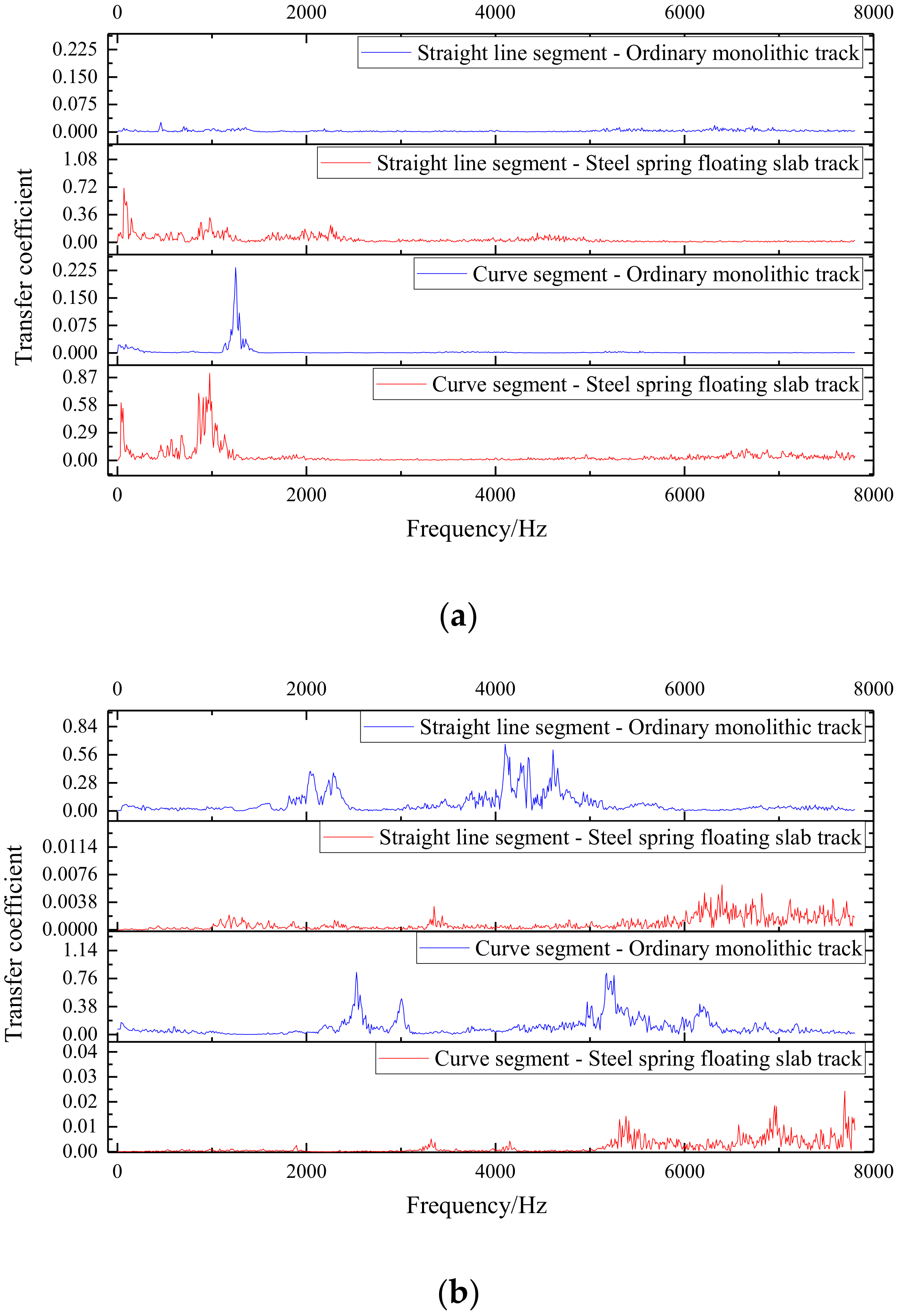
Therefore, according to the above method, the transmission coefficient analysis is performed on the measured vibration acceleration data, as shown in
Figure 22.
According to
Figure 22a, the vibration transmission of the rail–track bed under the four working conditions is mainly concentrated in the frequency band below 1484 Hz. The steel-spring-floating slab track has a high rail–track bed transfer rate in most frequency bands, especially in the frequency band of 39–68 Hz, the steel-spring-floating slab track rail–track bed transfer coefficient curve also has a peak point.
According to
Figure 22b, the vibration transmission between the track bed and the tunnel wall under the four working conditions is mainly concentrated in the middle and high frequency bands above 1806 Hz.
3.5. Z Vibration Level Analysis
According to “Measurement Method of Environmental Vibration in Urban Areas” GB10071-1988 [
32], the tunnel wall vibration data were analyzed according to ISO 2631/1-1997 [
33] vertical (Z-direction) weighting method (1~80 Hz). The Z vibration level (V
LZ) refers to the Z vibration level measured when the train passes through the measuring segment, and is the most commonly used evaluation index. However, since the running speed of the train will be different under different line conditions, it is necessary to correct the data of the Z vibration level according to the data of the train to balance the influence of the train speed on the result.
3.5.1. Train Speed Calculation
According to “Technical Guidelines for Environmental Impact Assessment—Urban Rail Transit. Beijing, China: Ministry of Ecology and Environment” HJ453-2008 [
34], for the environmental vibration caused by train operations, the train speed correction formula at different speeds is:
where:
v0—the reference speed of the source intensity, in km/h;
v—the running speed of the train, in km/h.
Therefore, the speed of the train needs to be calculated. In the analysis, the displacement-waveform bandpass filtering [
35,
36] is mainly used to obtain the displacement time- domain curve of the rail measuring point, as shown in
Figure 23.
The running speed of the train is calculated based on the time between the wheels and the distance between the wheels. Since the measured vehicle is a subway B-type vehicle [
37], the design speed of the vehicle is 80 km/h, and the basic parameters of the vehicle are shown in
Table 2. Therefore, it can be calculated that the data for the four operating conditions of straight line segment—ordinary monolithic track, straight line segment—steel-spring-floating slab track, curved segment—ordinary monolithic track, and curved segment—steel-spring-floating slab track are: 71.36 km/h, 73.00 km/h, 66.87 km/h, 63.16 km/h. It can be seen that the train speed in the straight line segment is higher than that in the curved segment.
3.5.2. Z Vibration Level and Insertion Loss Analysis
Take the data measured when 20 trains pass through the test section, analyze and statistically obtain the V
LZ value and the vibration difference V
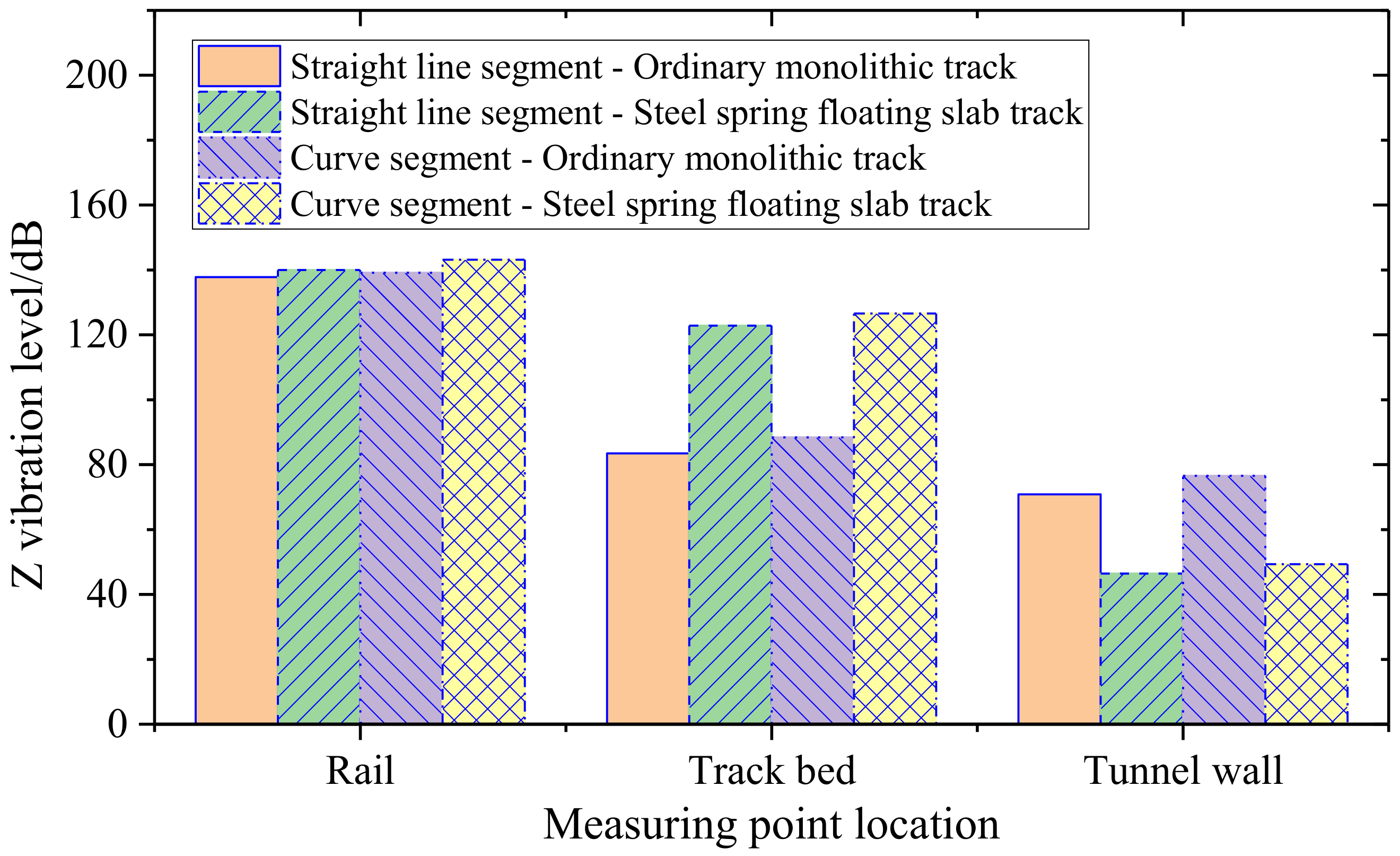
LZ of the tunnel wall measurement point of each test section under the two track bed forms. In order to compare the Z vibration levels of the track components under different line conditions, the above corrected Z vibration levels are counted, as shown in
Figure 24.
It can be seen from
Figure 24 that after the vehicle speed is corrected to the same speed, the Z vibration level of the tunnel wall in the steel-spring-floating slab track segment is significantly smaller than that in the ordinary monolithic track segment. For the ordinary monolithic track tunnel wall, the Z vibration level is located at 70.83~76.54 dB. The Z vibration level of the tunnel wall at the steel-spring-floating slab track is located at 46.41~49.33 dB. The insertion loss V
LZ of the straight line and the curved segment are 24.42 dB and 27.21 dB, respectively, and the average insertion loss V
LZ is 25.82 dB, indicating that the steel-spring-floating slab track has a significant vibration isolation effect.
4. Discussion
Existing research suggests relatively simple analysis methods for steel-spring-floating slab tracks. In this study, the vibration responses of rails, track beds and tunnel walls of steel-spring-floating slab tracks and ordinary monolithic tracks under straight and curved conditions are compared by using a variety of signal processing and analysis methods.
According to the results of the spectral (RMS) analysis, the frequency response of the tunnel wall in the steel-spring-floating slab track section is significantly reduced. Comparing
Figure 15a with
Figure 15b, it can be seen that compared with the ordinary monolithic track-tunnel-wall-acceleration amplitude spectrum in the straight line segment, the ordinary monolithic track-tunnel-wall-vibration acceleration amplitude spectrum in the curved segment has more peak points, and is larger in magnitude. This shows that the wheel-rail vibration in the curved segment is more complicated, which results in the phenomenon that more peak points appear in the acceleration spectrum of the ordinary monolithic track tunnel wall. For the above phenomenon, the steel-spring-floating slab track has a good reduction effect on these peak points, so it can ensure the vibration damping effect in the curve segment.
Comparing the frequency-division vibration level curves in
Figure 17, it can be seen that although the frequency-division vibration level curves of the rail and track bed are different in value, their shapes are basically the same. The attenuation of the sub-frequency vibration level of the steel-spring-floating slab track transmitted from the rail to the track bed is small. The reason is that the bottom of the steel-spring-floating slab track is suspended, and its restraint is less than that of the ordinary monolithic track, so the vibration effect is more significant. However, because the bottom of the ordinary monolithic track is fully constrained by rigidity, it is easier to transmit the vibration to the tunnel wall under the action of the dynamic load of the train, and the transmission capacity of high-frequency vibration is stronger, which leads to the similar frequency-division vibration level between the track bed and the tunnel wall of the ordinary monolithic track, in which the curves are closely spaced in the high-frequency range. Therefore, comparing the above phenomena, it can be seen that in the design of steel-spring-floating slab tracks, in order to limit the vibration of the track bed, it is necessary to appropriately increase the restraint at the bottom of the track bed, increase the number of vibration isolators, and appropriately increase the stiffness value.
For different line conditions, the frequency-division vibration level at the high frequency of the curved segment is significantly larger than that of the straight line segment, and the ordinary monolithic track and tunnel wall at steel-spring-floating slab track acceleration frequency-division vibration levels of the curved segment are both the maximum values near 5000 Hz, which shows that the setting of the curve segment will lead to aggravated vibration of the tunnel wall at high frequency.
In terms of vibration transmission, the vibration transmission characteristics of the rails, track bed and tunnel walls of the steel-spring-floating slab track and ordinary monolithic track have obvious field characteristics (
Figure 22). Comparing the rail–track transfer coefficient curves of the straight line segment and the curved segment, it can be seen that when passing through the curved segment, the rail–track bed transfer coefficient curves of the ordinary monolithic track and the steel-spring-floating slab track both show a new peak point at 791~1455 Hz. They are located at 1250.01 Hz and 976.56 Hz, respectively, and the transfer coefficient amplitudes are 0.233 and 0.915. Compared with the steel-spring-floating slab track, the track bed–tunnel wall vibration transfer curve of ordinary monolithic track has two peak regions in the mid-frequency region, and the peak regions are also different with the change of line conditions. The track bed–tunnel wall vibration-transfer peak at ordinary monolithic track areas in the straight line segment are located at 1806~2490 Hz and 3681~5136 Hz, and the track bed–tunnel wall vibration-transmission peak areas of the ordinary monolithic track in the curved segment are located at 2168~3134 Hz and 4912~6386 Hz. It can be seen that the frequency of the peak segment in the curved segment is higher and wider. The track bed–tunnel wall vibration transfer curve of the steel-spring-floating slab track is mainly located in the high frequency above 5107 Hz, and the peak range and peak value of the transfer coefficient curve in the curved segment are larger than those in the straight line segment, and the two main peak areas appearing in the transfer coefficient curve of the ordinary monolithic track are eliminated. The reason for the difference is that the basic setting of the track structure in the curved segment is different.
5. Conclusions
By designing a vibration test scheme for subway lines, the vibration tests were carried out on the cumulative four working conditions of ordinary monolithic track and steel-spring-floating slab track under different line conditions (straight line and curved segment) with similar speeds. The vibration responses of rail, track bed, and tunnel wall under real train loads under four working conditions were mainly studied. Based on various time-frequency analysis methods, the vibration of track components under different working conditions was comprehensively analyzed, and the following results were obtained:
(1) According to the time domain, frequency domain and Z vibration level analysis results, it is shown that steel-spring-floating slab track can significantly reduce the acceleration response of the tunnel wall, and all kinds of vibration indicators at the tunnel wall are larger for the ordinary monolithic track, indicating that steel-spring-floating slab tracks can significantly reduce the impact of subway trains on the surrounding environment.
(2) By comparing the time-frequency curves of rail, track bed, and tunnel walls, it can be seen that under the action of train loads, the dynamic responses of the rail under the four working conditions are relatively close, where the steel-spring-floating slab track is slightly larger than that of the ordinary monolithic track, and the acceleration steel-spring- floating slab track of the track bed is significantly larger than that of the ordinary monolithic track.
(3) In the case of two different lines, the driving speed of the curved segment is lower than that of the straight line segment, but the vibration response generated by it is significantly larger than that of the straight line segment, and each frequency band will generate more peak points, and the high-frequency vibration will be more severe. At the same time, the comparison of the two track structures shows that the vibration of the ordinary monolithic track is more easily affected by the line conditions.
(4) According to the frequency-response transfer analysis between the track components, it can be seen that the rail-track bed vibration transfer rate of the steel-spring-floating slab track is significantly greater than that of the ordinary monolithic track, while the vibration transfer rate of its track bed-tunnel wall is significantly smaller than that of the common integral-track bed track. It shows that for the steel-spring-floating slab track, one needs to pay more attention to the vibration control of its track bed in the process of use to ensure the safety and stability of subway trains.
Meanwhile, the countable effect and possible impact on the optimization design of the steel-spring-floating slab track are put forward as follows:
(1) At present, the research methods for the dynamic characteristics of the steel-spring-floating slab track are relatively simple, and a deeper exploration of the dynamic characteristics of the steel-spring-floating slab track is carried out to further reveal the vibration reduction and transmission mechanism of the steel-spring-floating slab track, and then optimize the track structure and the design of the vibration isolator.
(2) In this study, a variety of time-frequency analysis methods were used to compare the dynamic characteristics of the cast-in-place steel-spring-floating slab track under different line conditions, and further reveal the vibration characteristics of the cast-in-place steel-spring-floating slab track in the actual vehicle-operating environment. At the same time, it can be seen that the vibration in the curved section is more random.
(3) Therefore, it is recommended to limit the speed of subway trains in curved segment, and take more limiting measures for steel-spring-floating slab track, such as adding lateral limit vibration isolators to control the dynamic response of steel-spring-floating slab track in a curved segment. According to the results of the transmission analysis, the corresponding dynamic vibration absorption device can also be designed according to the transmission peak frequency band analyzed in this study to achieve the effect of reducing the vibration transmission.
Future outlook: With the increasing requirements for vibration reduction of railway tracks, the steel-spring-floating slab track will not only be used in the main line in the subway tunnel, but also may be used in areas with complex line conditions such as turnouts and stations. With the development of society, the urban population will be denser, and the steel-spring-floating slab track will inevitably be used in the field of high-speed railway and urban express lines in the future. Therefore, the development of the subsequent steel-spring-floating slab track will inevitably develop in the direction of complex line shape, high axle load, and high speed. In this study, the measured vibration response of the steel-spring-floating slab track under the curve condition was compared and analyzed, which is beneficial to provide an experimental case for the subsequent design optimization of the steel-spring-floating slab track.


 ,
, 


