
Experimental Analysis of Constrained Layer Damping Structures for Vibration Isolation in Lightweight Railway Vehicles

 , ,
, ,  , ,
, ,  , and
, and
Abstract
:1. Introduction
2. Experimental Study
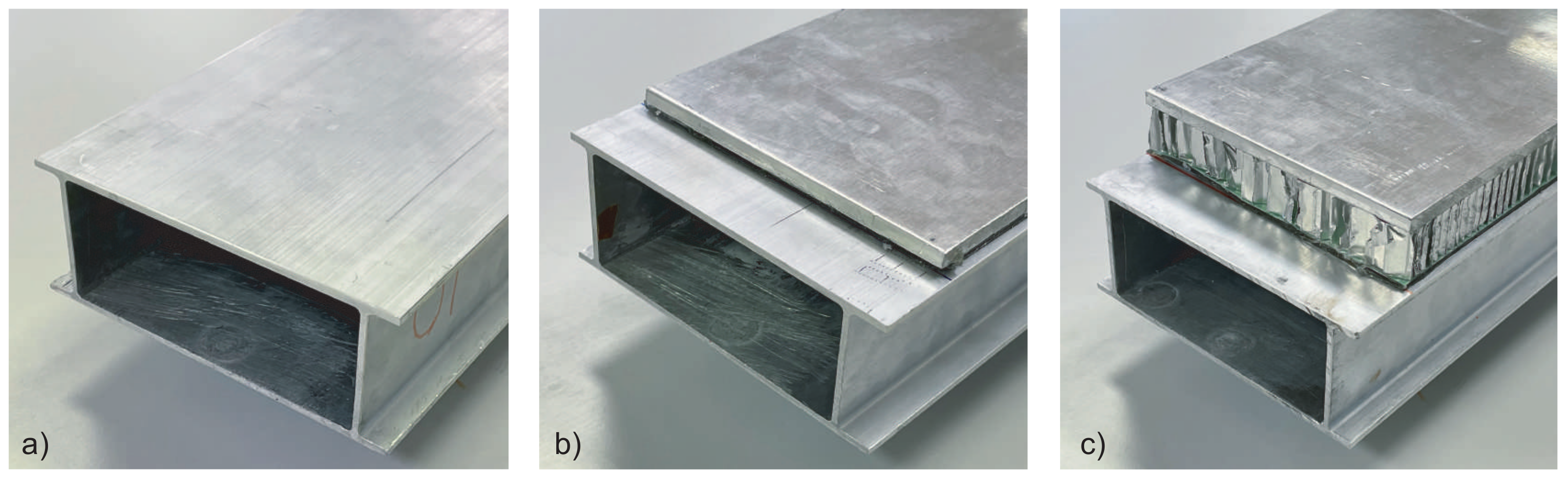
2.1. Ligthweight Car Body Specimen
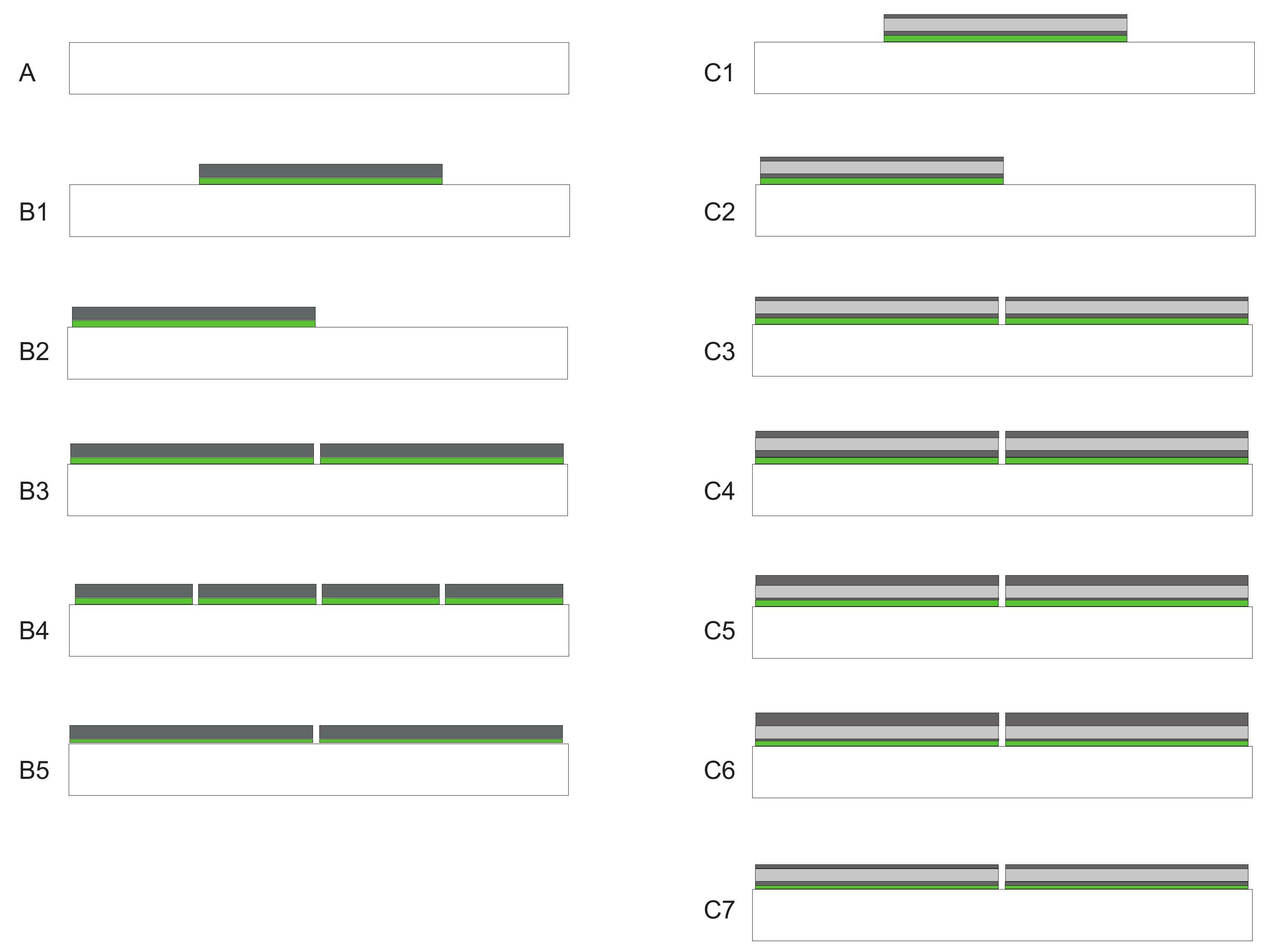
2.2. CLD Type and Location
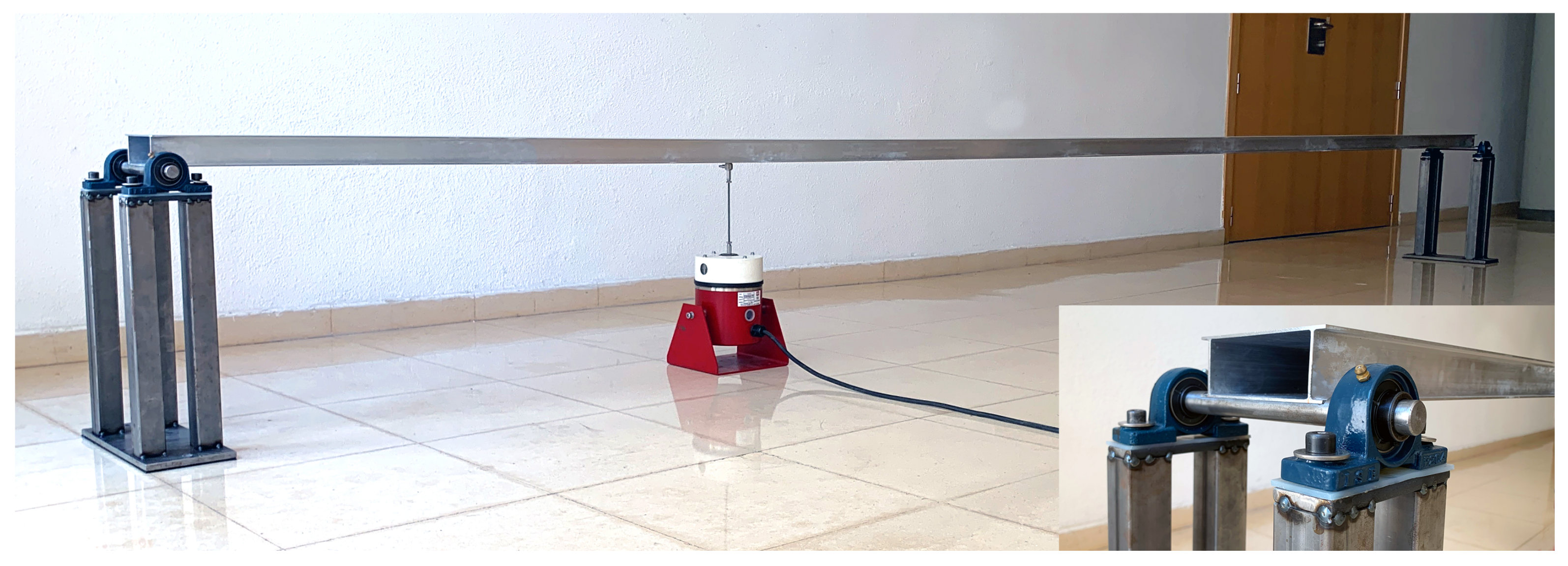
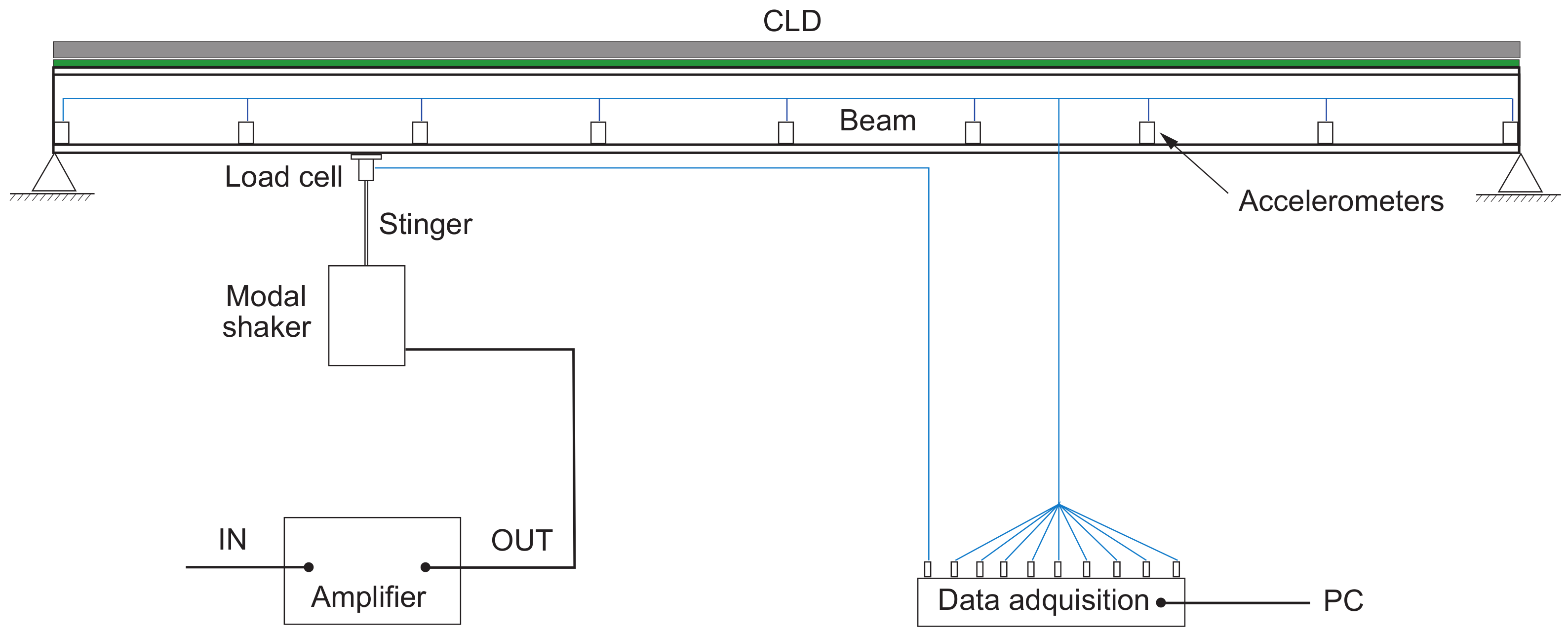
2.3. Test Bench
3. Experimental Results
4. Conclusions
Author Contributions
Funding
Acknowledgments
Conflicts of Interest
References
- Zhou, J.; Goodall, R.; Ren, L.; Zang, H. Influences of car body vertical flexibility on ride quality of passenger railway vehicles. Proc. IMechE Part F J. Rail Rapid Transit. 2009, 223, 461–471. [Google Scholar] [CrossRef]
- Nashif, A.; Jones, D.; Henderson, J. Vibration Damping; John Wiley: New York, NY, USA, 1985. [Google Scholar]
- Mead, D. Passive Vibration Control; John Wiley & Sons: Chichester, UK, 1998. [Google Scholar]
- Rao, M. Recent applications of viscoelastic damping for noise control in automobiles and commercial airplanes. J. Sound Vib. 2003, 262, 457–474. [Google Scholar] [CrossRef]
- Fan, R.; Meng, G.; Yang, J.; He, C. Experimental study of the effect of viscoelastic damping materials on noise and vibration reduction within railway vehicles. J. Sound Vib. 2009, 319, 58–76. [Google Scholar] [CrossRef]
- Furukava, M.; Gerges, S.; Neves, M.; Coelho, B. Analysis of structural damping performance in passenger vehicles chassis. J. Acoust. Soc. Am. 2009, 126, 2280. [Google Scholar] [CrossRef]
- Danti, M.; Vige, D.; Nierop, G. Modal methodology for the simulation and optimization of the free-layer damping treatment of a car body. J. Vib. Acoust. 2010, 132, 021001. [Google Scholar] [CrossRef]
- Giannella, V.; Branda, F.; Passaro, J.; Petrone, G.; Barbarino, M.; Citarella, R. Acoustic improvements of aircraft headrests based on Electrospun Mats evaluated through Boundary Element Method. Appl. Sci. 2020, 10, 5712. [Google Scholar] [CrossRef]
- Giannella, V.; Colangeli, C.; Cuenca, J.; Citarella, R.; Barbarino, M. Experimental/Numerical acoustic assessment of aircraft seat headrests based on Electrospun Mats. Appl. Sci. 2020, 11, 6400. [Google Scholar] [CrossRef]
- Fomin, O.; Gorbunov, M.; Lovska, A.; Gerlici, J.; Kravchenko, K. Dynamics and strength of circular tube open wagons with aluminum foam filled center sills. Materials 2021, 14, 1915. [Google Scholar] [CrossRef]
- Fomin, O.; Gorbunov, M.; Gerlici, J.; Vatulia, G.; Lovska, A.; Kravchenko, K. Research into the strength of an open wagon with double sidewalls filled with aluminium foam. Materials 2021, 14, 3420. [Google Scholar] [CrossRef]
- Alam, N.; Asnani, N. Vibration and damping analysis of multilayered rectangular plates with constrained viscoelastic layers. J. Sound Vib. 1984, 97, 597–614. [Google Scholar] [CrossRef]
- Yildiz, A.; Stevens, K. Optimum thickness distribution of unconstrained viscoelastic layer treatment for plates. J. Sound Vib. 1985, 103, 183–199. [Google Scholar] [CrossRef]
- Nokes, D.; Nelson, F. Constrained layer damping with partial coverage. Shock Vib. 1968, 38, 5–10. [Google Scholar]
- Parathasarathy, G.; Reddy, C.; Ganesan, N. Partial coverage of rectangular plates by unconstrained layer damping treatments. J. Sound Vib. 1985, 102, 203–216. [Google Scholar] [CrossRef]
- Lall, A.; Asnani, N.; Nakra, B. Vibration and damping analysis of rectangular plate with partially covered constrained viscoelastic layer. J. Vib. Acoust. Stress. Reliab. Des. 1987, 109, 241–247. [Google Scholar] [CrossRef]
- Lall, A.; Asnani, N.; Nakra, B. Damping analysis of partially covered sandwich beams. J. Sound Vib. 1988, 123, 247–259. [Google Scholar] [CrossRef]
- Zheng, H.; Cai, C.; Pau, G.; Liu, G. Minimizing vibration response of cylindrical shells through layout optimization of passive constrained layer damping treatments. J. Sound Vib. 2005, 279, 739–756. [Google Scholar] [CrossRef]
- Zheng, L.; Xie, R.; Wang, Y.; Adel, E. Topology optimization of constrained layer damping on plates using Method of Moving Asymptote MMA approach. Shock Vib. 2011, 18, 221–244. [Google Scholar]
- Ansari, M.; Khajepour, A.; Esmailzadeh, E. Application of level set method to optimal vibration control of plate structures. J. Sound Vib. 2013, 332, 687–700. [Google Scholar] [CrossRef]
- Takezawa, A.; Daifuku, M.; Nakano, Y.; Nakagawa, K.; Yamamoto, T.; Kitamura, M. Topology optimization of damping material for reducing resonance response based on complex dynamic compliance. J. Sound Vib. 2016, 365, 230–243. [Google Scholar] [CrossRef]
- Liu, Q.; Ruan, D.; Huang, X. Topology optimization of viscoelastic materials on damping and frequency of macrostructures. Comput. Methods Appl. Mech. Eng. 2018, 337, 305–323. [Google Scholar] [CrossRef]
- Xie, X.; Zheng, H.; Jonckheere, S.; Desmet, W. Explicit and efficient topology optimization of frequency-dependent damping patches using moving morphable components and reduced-order models. Comput. Methods Appl. Mech. Eng. 2019, 355, 591–613. [Google Scholar] [CrossRef]
- Madeira, J.; Araújo, A.; Soares, C.M. Multiobjective optimization of constrained layer damping treatments in composite plate structures. Mech. Adv. Mater. Struct. 2017, 24, 427–436. [Google Scholar] [CrossRef]
- Verboven, P.; Guillaume, P.; Cauberghe, B.; Vanlanduit, S.; Parloo, E. Modal parameter estimation from input-output Fourier data using frequency-domain maximum likelihood identification. J. Sound Vib. 2004, 276, 957–979. [Google Scholar] [CrossRef]
- El-Kafaty, M.; Peeters, B.; Guillaume, P.; De Trover, T. Constrained maximum likelihood modal parameter identification applied to structural dynamics. Mech. Syst. Signal Process. 2007, 72–73, 567–589. [Google Scholar]


| Specimen | Polymer | Core | Upper Layer | Lower Layer | CLD | CLD |
|---|---|---|---|---|---|---|
| Thickness (mm) | Layer | Thickness (mm) | Thickness (mm) | Length (m) | Added Mass (kg) | |
| A | - | - | - | - | - | - |
| B1 | 2 | ALU6 | - | - | 1 × 2.50 | 5.6 |
| B2 | 2 | ALU6 | - | - | 1 × 2.50 | 5.6 |
| B3 | 2 | ALU6 | - | - | 2 × 2.50 | 11.3 |
| B4 | 2 | ALU6 | - | - | 4 × 1.25 | 11.3 |
| B5 | 1 | ALU6 | - | - | 2 × 2.50 | 10.7 |
| C1 | 2 | HC20 | 1 | 1 | 1 × 2.50 | 2.8 |
| C2 | 2 | HC20 | 1 | 1 | 1 × 2.50 | 2.8 |
| C3 | 2 | HC20 | 1 | 1 | 2 × 2.50 | 5.6 |
| C4 | 2 | HC20 | 2 | 2 | 2 × 2.50 | 8.9 |
| C5 | 2 | HC20 | 4 | 0.25 | 2 × 2.50 | 9.4 |
| C6 | 2 | HC20 | 6 | 0.25 | 2 × 2.50 | 12.7 |
| C7 | 1 | HC20 | 1 | 1 | 2 × 2.50 | 8.4 |
| Mode 1 | Mode 2 | Mode 3 | |||||||
|---|---|---|---|---|---|---|---|---|---|
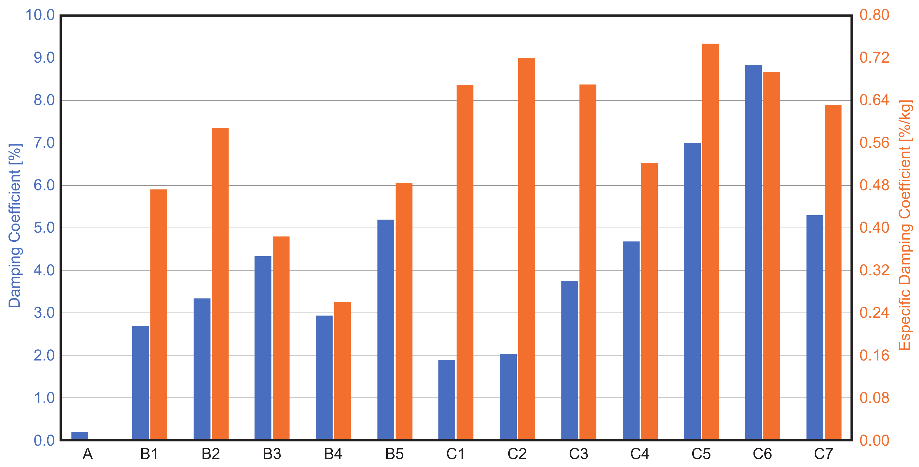
| Specimen | [Hz] | [%] | [%/kg] | [Hz] | [%] | [%/kg] | [Hz] | [%] | [%/kg] |
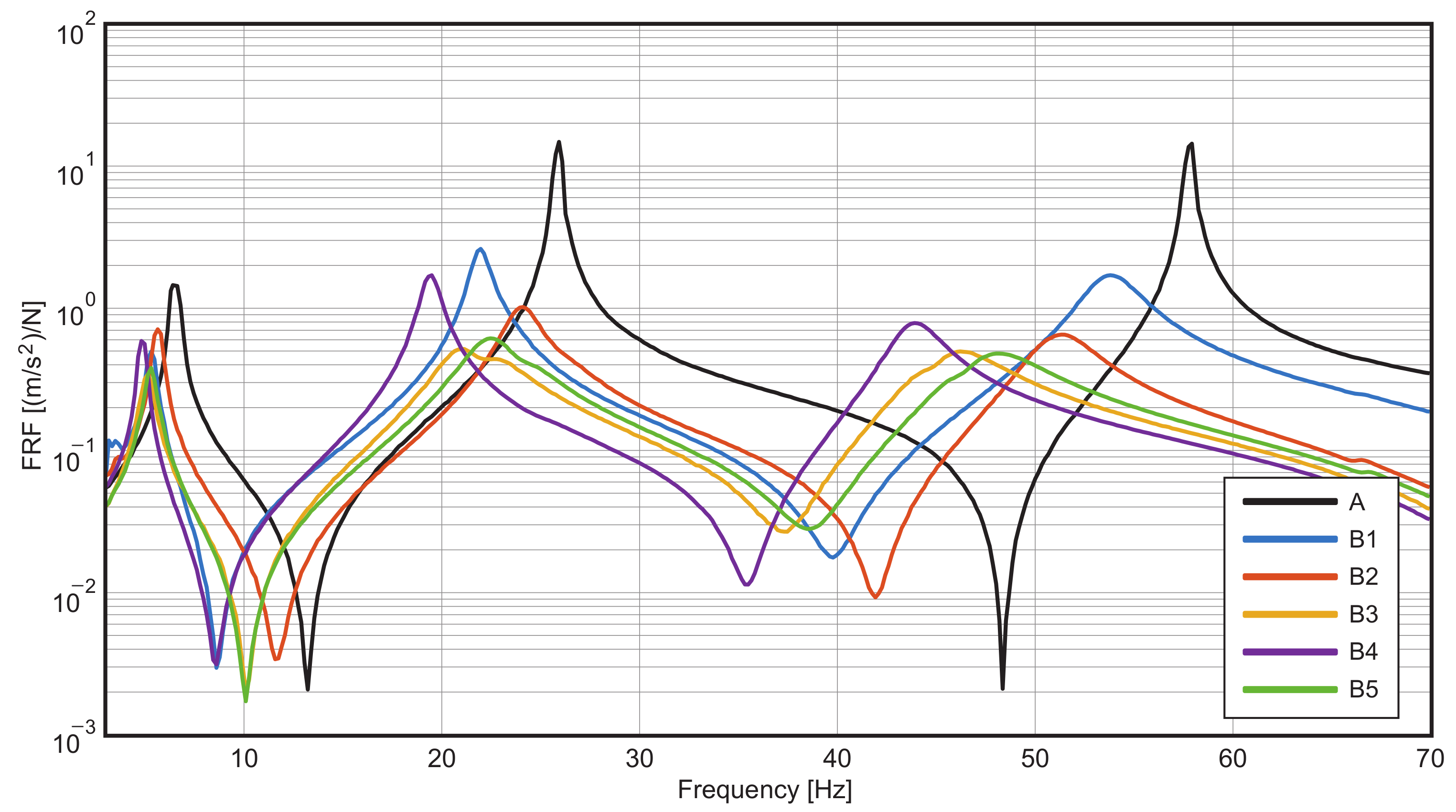
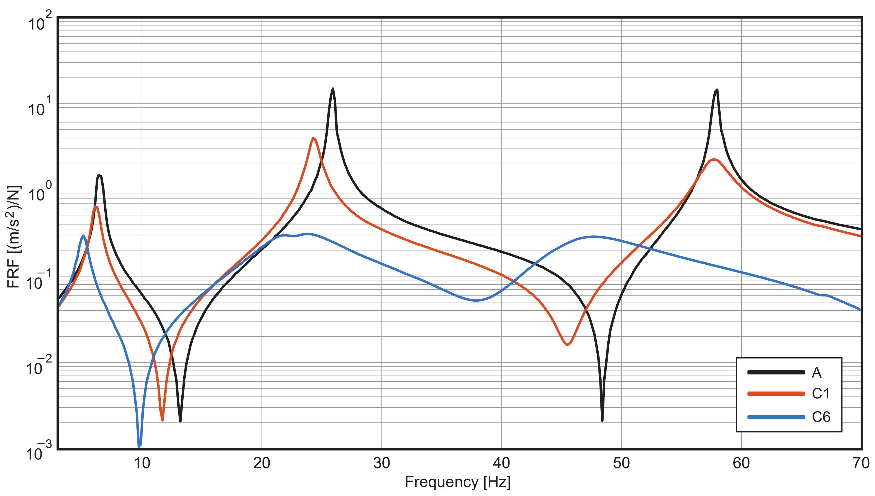
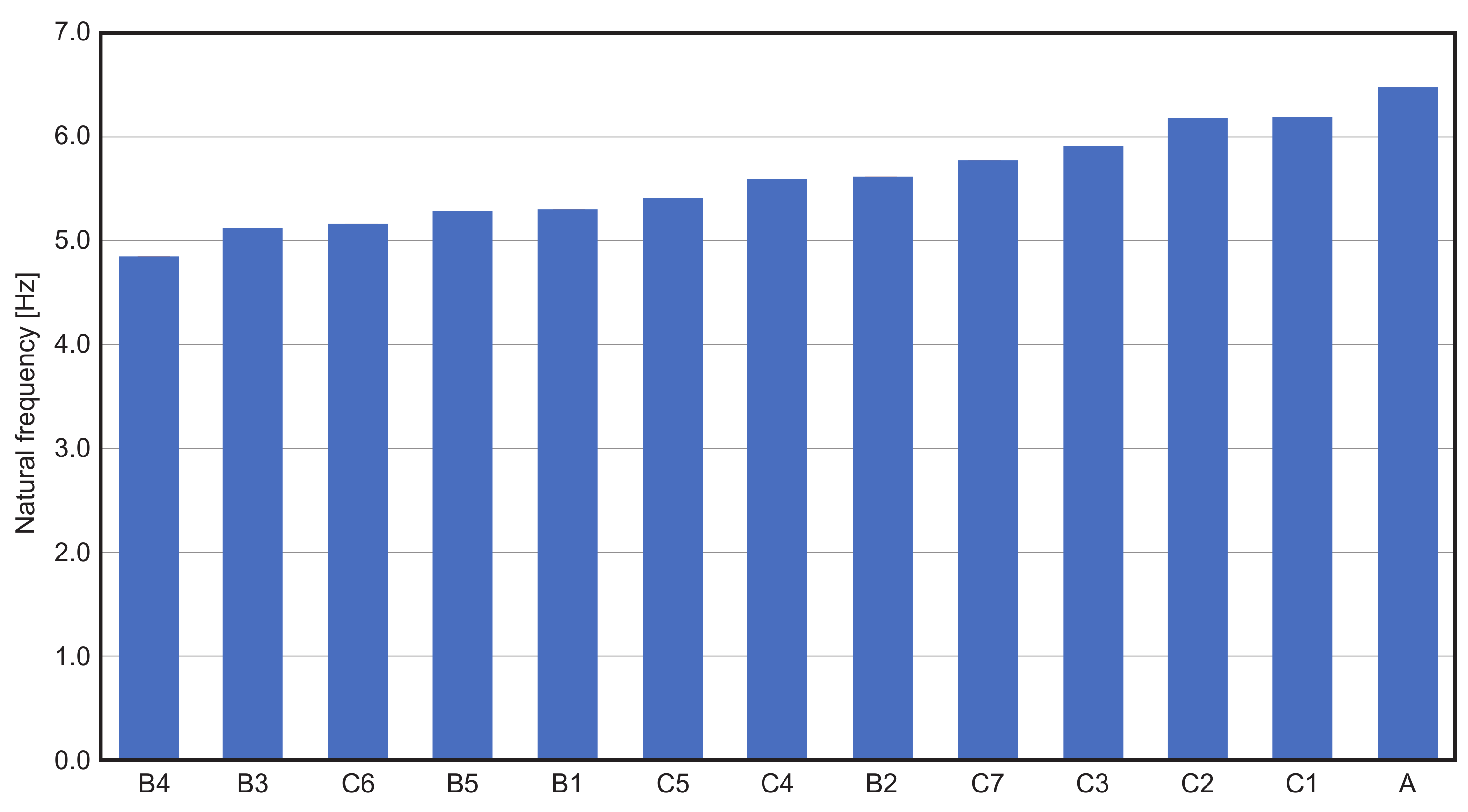
| A | 6.5 | 0.3 | - | 25.9 | 0.2 | - | 57.8 | 0.2 | - |
| B1 | 5.3 | 3.8 | 0.67 | 21.9 | 1.7 | 0.31 | 53.8 | 2.7 | 0.47 |
| B2 | 5.6 | 2.6 | 0.46 | 24.1 | 3.7 | 0.65 | 51.2 | 3.3 | 0.59 |
| B3 | 5.1 | 4.6 | 0.40 | 21.7 | 8.8 | 0.78 | 45.9 | 4.3 | 0.38 |
| B4 | 4.9 | 1.2 | 0.10 | 19.4 | 2.2 | 0.19 | 43.9 | 2.9 | 0.26 |
| B5 | 5.3 | 4.3 | 0.40 | 22.5 | 6.0 | 0.56 | 47.8 | 5.2 | 0.48 |
| C1 | 6.2 | 3.3 | 1.19 | 24.4 | 1.5 | 0.55 | 57.6 | 1.9 | 0.67 |
| C2 | 6.2 | 1.6 | 0.56 | 25.3 | 2.8 | 1.00 | 55.0 | 2.0 | 0.72 |
| C3 | 5.9 | 3.0 | 0.54 | 24.7 | 5.5 | 0.98 | 53.1 | 3.7 | 0.67 |
| C4 | 5.6 | 3.2 | 0.35 | 23.8 | 8.2 | 0.92 | 50.3 | 4.7 | 0.52 |
| C5 | 5.4 | 4.3 | 0.46 | 23.5 | 10.5 | 1.13 | 49.5 | 7.0 | 0.75 |
| C6 | 5.2 | 7.0 | 0.55 | 23.4 | 15.0 | 1.17 | 46.7 | 8.9 | 0.70 |
| C7 | 5.8 | 4.0 | 0.48 | 25.1 | 8.8 | 1.05 | 51.7 | 5.3 | 0.63 |
Publisher’s Note: MDPI stays neutral with regard to jurisdictional claims in published maps and institutional affiliations. |
© 2022 by the authors. Licensee MDPI, Basel, Switzerland. This article is an open access article distributed under the terms and conditions of the Creative Commons Attribution (CC BY) license (https://creativecommons.org/licenses/by/4.0/).
Share and Cite
Melero, M.; Nieto, A.J.; Morales, A.L.; Palomares, E.; Chicharro, J.M.; Ramiro, C.; Pintado, P. Experimental Analysis of Constrained Layer Damping Structures for Vibration Isolation in Lightweight Railway Vehicles. Appl. Sci. 2022, 12, 8220. https://doi.org/10.3390/app12168220
Melero M, Nieto AJ, Morales AL, Palomares E, Chicharro JM, Ramiro C, Pintado P. Experimental Analysis of Constrained Layer Damping Structures for Vibration Isolation in Lightweight Railway Vehicles. Applied Sciences. 2022; 12(16):8220. https://doi.org/10.3390/app12168220
Chicago/Turabian StyleMelero, Miguel, Antonio J. Nieto, Angel L. Morales, Eduardo Palomares, Jose M. Chicharro, Carmen Ramiro, and Publio Pintado. 2022. "Experimental Analysis of Constrained Layer Damping Structures for Vibration Isolation in Lightweight Railway Vehicles" Applied Sciences 12, no. 16: 8220. https://doi.org/10.3390/app12168220
APA StyleMelero, M., Nieto, A. J., Morales, A. L., Palomares, E., Chicharro, J. M., Ramiro, C., & Pintado, P. (2022). Experimental Analysis of Constrained Layer Damping Structures for Vibration Isolation in Lightweight Railway Vehicles. Applied Sciences, 12(16), 8220. https://doi.org/10.3390/app12168220