Article

Efficiency of Different Cage Armour Systems

Department of Weapon Systems and Ballistics, Royal Military Academy, Renaissance Avenue 30, 1000 Brussels, Belgium
Appl. Sci. 2022, 12(10), 5064; https://doi.org/10.3390/app12105064
Submission received: 25 February 2022 / Revised: 3 May 2022 / Accepted: 6 May 2022 / Published: 17 May 2022
(This article belongs to the Special Issue Armour and Protection Systems, Volume II)

Abstract

:

Featured Application

This article describes the state of the art of current cage armour systems and compares their efficiencies after experimental validation of the efficiency calculation method.

Abstract

Cage armour systems have been in use since the 1960s and are still being used extensively on many armoured vehicles up to this day to offer protection against mainly a number of RPG-7 shaped charge warheads. Nevertheless, many misunderstandings still exist up to this day as well as regarding their working principle as regarding their actual efficiency. This article will start by exploring the origins of the current cage armour systems and by explaining the working principle behind them. This will be followed by the development of a methodology to calculate the efficiency of different types of cage armour systems (slat, bar, net and inertial distributed weight systems) as a function of impact conditions for a specific RPG-7 shaped charge warhead. The results of the developed methodology will be compared to experimental results for four different cage armour systems, in order to validate the followed approach. It will then be applied to different cage armour systems in order to calculate their overall ballistic and mass efficiency as a function of the impact angle. The analysis will finally be refined taking into account the likely impact conditions for an RPG-7 shaped charge warhead, based on a simple trajectory model.

1. Introduction

In the recent and current operational theatres such as Afghanistan, Iraq or Syria, a major threat to light and even heavy armoured vehicles are portable antitank weapon systems from the Soviet RPG-7 family [1,2,3] (Figure 1a). Due to their high proliferation, their easy portability and low complexity, combined with a very high penetration capacity, the RPG-7 family of weapon systems form a real threat both to light and heavy armoured vehicles. This high penetration capacity is due to the use of a shaped charge warhead for the antitank ammunitions of the RPG-7 family of weapon systems, giving a minimum penetration of 300 mm in rolled homogeneous armour for the most basic versions [4]. Even if recent statistics [5] indicate that losses due to the use of the RPG-7 system are relatively limited (the available statistics, however, do not allow determining if this is due to limited use or a limited efficiency of the system), many countries have equipped their vehicles with a so-called cage armour system in order to counter the ubiquitous threat posed by the RPG-7 weapon system, especially by its antitank warheads (the RPG-7 system can use different types of ammunition including antitank and fragmenting antipersonnel rounds).
This ‘bird cage’ (Figure 1b) put around the vehicle exploits a specific weakness in the design of the detonation chain of two of the most common antitank rounds for the RPG-7 system, using, respectively, the PG-7 warhead (the oldest and likely most proliferated antitank ammunition for this system) and the PG-7M warhead (based on the same functioning mechanism as the original PG-7, but having a smaller maximum diameter). Next to these two very widespread types of ammunition, a number of other Soviet types of ammunition work on the same principle, e.g., the PG-7L warhead also for the RPG-7 weapon system, the warhead of the RPG-18 disposable antitank rocket launcher, and of the SPG-9 recoilless rifle.
Contrary to what many may believe, the main defeat mechanism for the PG-7(M) warhead, when fired against such a cage armour system, is not based on an increase in standoff distance, as with the so-called ‘bazooka plates’ from World War II (Figure 1c). A simple comparison between the two types of protection clearly shows the much more complex (and hence expensive) geometry of a typical cage armour system when compared with the simple sheets used for the historical bazooka plates, which would have sufficed if the goal was only to create standoff distance.

2. Cage Armour Working Principle

Many misunderstandings still exist around the working principle of cage armour, as illustrated even recently by the (useless) addition of cage armour systems on the turrets of Russian main battle tanks to counter guided missiles [6,7,8,9]. In order to understand cage armour, it is essential to first describe the main threat that is being countered by the cage armour, namely the RPG-7 weapon system with its basic antitank ammunition being the PG-7 and PG-7M rounds.

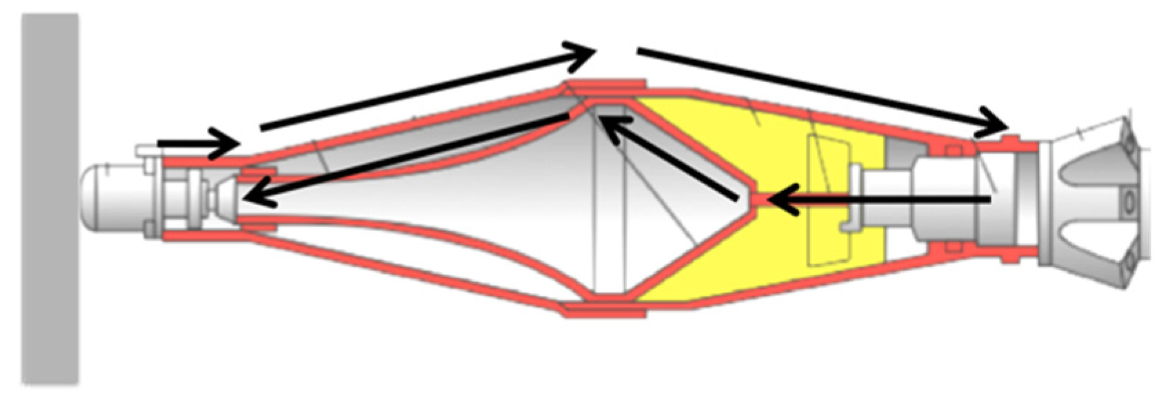
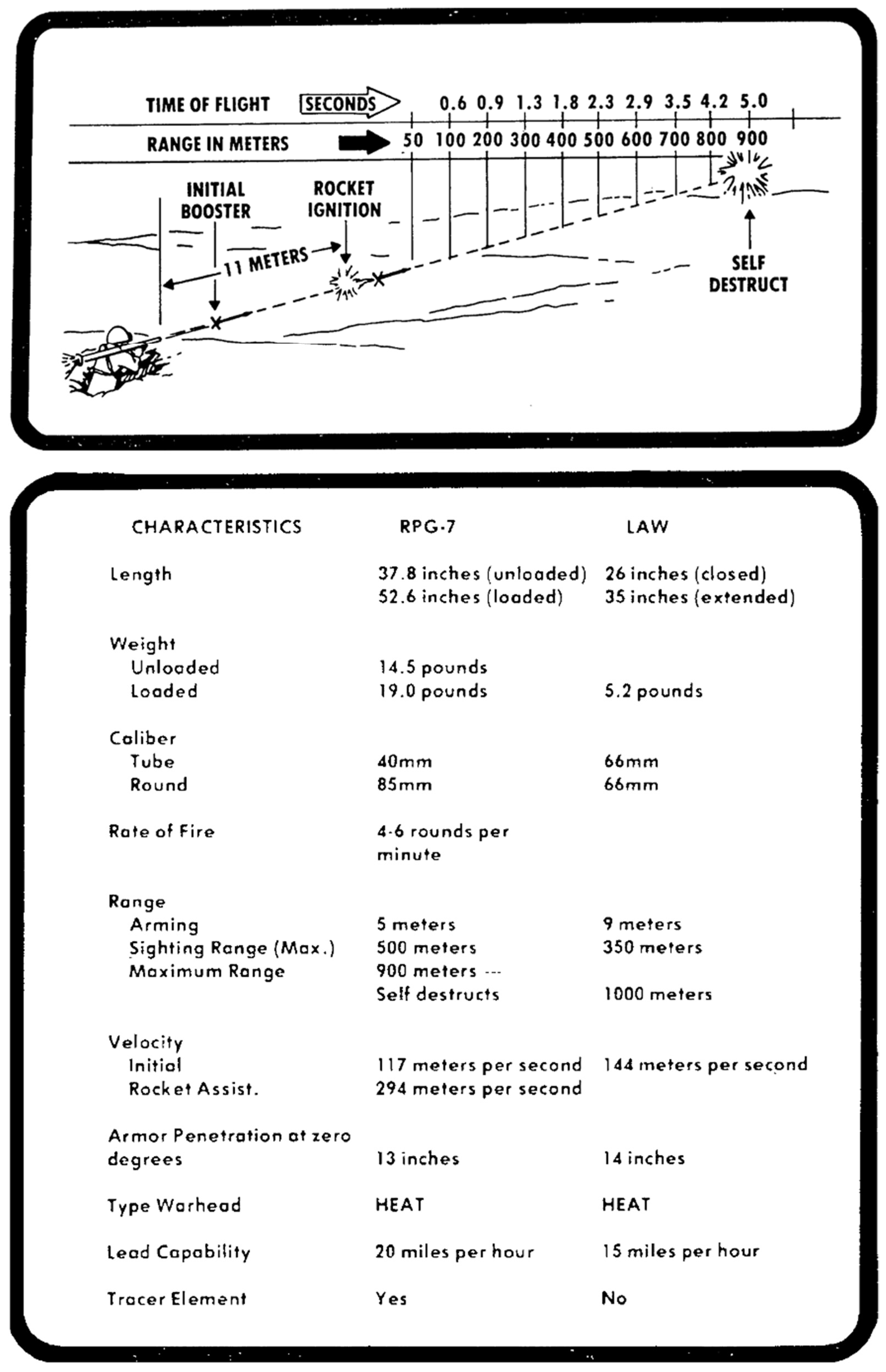
2.1. PG-7(M) Detonation Chain

The PG-7(M) round consists of two parts, as shown in Figure 2. The first part contains the warhead and a fixed rocket engine. The second part, which is screwed onto the base of the first part just before using the round, contains the folding fins to stabilize the rocket on its flight towards the target, next to a booster charge, which serves to propel the rocket to a safe distance from the launcher before ignition of the rocket engine. The latter method of firing prevents the shooter from being injured by the hot exhaust of the rocket engine upon firing.
The detonation chain of the PG-7(M) warhead is based on a specific design for the electrical circuit used to trigger the detonator. This circuit runs from the piezoelectric element in the nose of the projectile (which will produce a voltage difference and hence a current upon impact on a hard surface used to initiate the detonator) to the detonator in the back of the warhead. The produced current passes over the external, conical metal skin of the projectile (which also serves as the nose part of the complete projectile and hence determines largely the aerodynamic profile of the projectile) and is closed using a metal connector from the detonator to the liner, over the liner and finally a second, inner metallic trumpet-shaped cone. Isolating rings between the inner and outer cone prevent the current from passing from the outer to the inner cone without passing through the piezoelectric element and the detonator. Both the inner and outer metallic cones are typically made out of a thin aluminium sheet, yet rounds can be found that use mild steel for the outer cone as well (it is not clear if the steel has been used for the inner cone as well).
When the projectile is fired and hits a hard target, the pressure developed in the piezoelectric element will cause a voltage difference to occur over the piezoelectric element as shown in Figure 3. This voltage will cause a current to flow in the circuit formed by the piezoelectric element, the outer cone, the detonator, the liner and the inner cone back to the piezoelectric element. This current will initiate the detonator, which, in turn, will initiate the explosive of the shaped charge. The specific geometry of the nose of the projectile will also ensure that the shaped charge is triggered at an optimum standoff distance from the target.

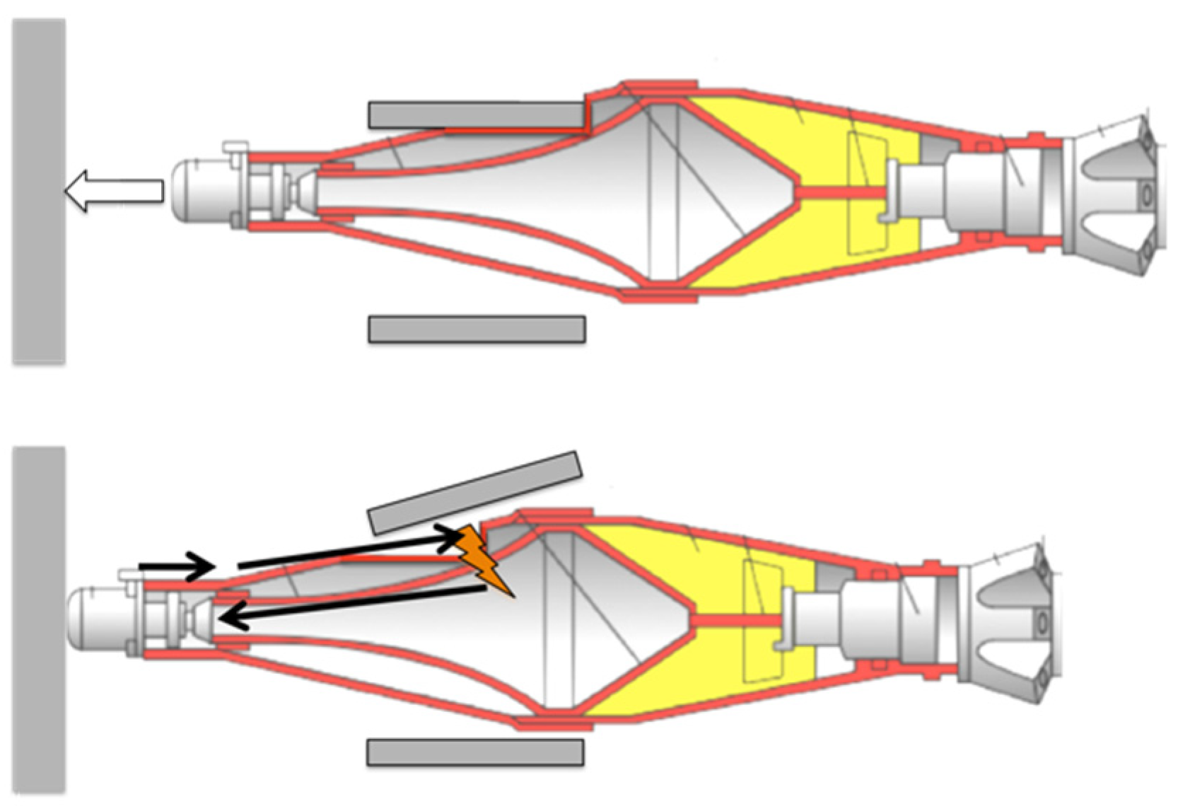
2.2. Cage Armour Working Principle

The working principle of the cage armour consists of short-circuiting the detonation chain of the warhead in such a way that current will no longer flow through the detonator upon the impact of the piezoelectric element on the target, generally the armoured hull of a fighting vehicle. This short-circuit is caused by the local deformation of the outer metallic cone by the cage armour; thus that it is in immediate contact with the inner cone upon impact. If this short-circuit can indeed be accomplished (and maintained) before the piezoelectric element impacts the target, the main current will no longer flow to the detonator but will return to the piezoelectric element through the short-circuit (Figure 4). Only a very small current will still flow to the detonator due to the high resistance of the detonator and the fact that the short-circuit, with very low resistance, and the detonator are forming a parallel circuit with the piezoelectric element as a power source. This very small current will normally be insufficient to trigger the detonator.
A secondary effect of the cage armour is the possible damage done to the liner of the shaped charge, even if insufficient damage has been done to the warhead to cause a short-circuit in the detonation chain. Although this can significantly reduce the penetration capacity of the warhead, this is in most cases not sufficient to protect light armoured vehicles from a complete perforation of the hull [10]. However, for main battle tanks, this reduction in penetration capacity can be sufficient to avoid a complete perforation of their armour.
A possible negative side-effect of the cage armour is the possibility that the explosive material in the short-circuited warhead still detonates upon impact on the main armour. This may be caused simply by the shock at impact [11] or by the impact of the hot and possibly still burning rocket engine into the explosive material after impacting the vehicle hull. In the worst case, this may lead to spalling on the backside of the armour, although modern combat vehicles are equipped with additional spall liners on the inner surface of the vehicle hull, effectively mitigating this effect.

2.3. Cage Armour Design Principle

From Section 2.2. it is possible to deduce the four main design principles for an optimized cage armour system.
Firstly, the horizontal and/or vertical distance between the structural parts of the slat armour should not be larger than the maximum diameter of the projectile against which the cage armour is designed to offer protection. Failing to do so will offer a possibility for an impacting projectile to pass between the structural parts of the cage armour without any interference with the latter. This leads to a maximum allowable horizontal and/or vertical distance between the cage armour parts of ±85 mm and ±72 mm for, respectively, the PG-7 and PG-7M warheads. In reality, this distance has to be slightly smaller than the maximum diameter of the projectile to assure sufficient deformation of the outer cone to cause and maintain a short-circuit until the impact of the piezoelectric element on the hull of the target.
In order to assure sufficient interaction between the cage armour components and the projectile, the cage armour must, of course, also offer sufficient resistance, either by strength or by inertia, or a combination of both. This leads to a second design principle being to determine minimum dimensions for the cage armour components to have sufficient strength, stiffness and/or inertia.
Thirdly, the piezoelectric element may not be allowed to come into contact with the hull of the target before a short-circuit has been caused by the cage armour. For this, it is important to put the cage armour at a minimum standoff distance from the hull corresponding to the distance existing between the piezoelectric element in the nose of the projectile on the one side and the projectile nose section with the maximum diameter on the other hand. For the PG-7(M) projectile this corresponds with a minimum standoff distance of ±190 mm. In practical applications, the selected standoff distance is generally considerably larger. This makes sure that there has been sufficient interaction between the cage armour components and the incoming projectile before the latter comes into contact with the hull of the vehicle. In certain cases, this might also lead to significant damage to the liner of the shaped charge, further reducing the risk of having a complete perforation of the hull. Additional advantages of this larger standoff are also that local variations in the geometry of the vehicle (e.g., the presence of boxes, connectors, handles, equipment, etc.) will not lead locally to a too-small standoff distance, next to reducing the blast effects on the hull of any explosive projectile impacting on the cage armour system.
Last but not least, the probability that the piezoelectric element (with a diameter of ±20 mm) impacts directly on the cage armour system instead of in-between its components must be minimized, as an impact of the piezoelectric element directly on the cage armour will generally lead to triggering of the detonator. The latter will initiate the shaped charge in a regular fashion. Although the standoff will be slightly increased compared to an impact directly onto the vehicle hull, it will, in almost all cases, not be sufficient to significantly lower the penetration capacity of the shaped charge (above 300 mm for even the most basic versions) to avoid a complete perforation of the armoured hull (see [4] for the residual penetration capacity of the PG-7 warhead as a function of standoff). This means that the horizontal and vertical distance between the different cage armour components must be maximized, but still taking into account the first principle that a projectile should not be able to pass between the cage armour components. Minimizing the probability of a direct hit on the cage armour components also dictates minimizing the dimensions of these components, but this is in conflict with the second principle that sufficient damage must be caused to the warhead to assure a short-circuit in the detonation chain.
The last design principle illustrates why cage armour is considered to be a ‘statistical armour,’ as based on the actual dimensions of the system, the impact conditions, and the type of incoming projectile, there is a certain probability that the cage armour will (if the piezoelectric element passes between the cage armour components) or will not work (if the piezoelectric element impacts on the cage armour components) as intended.

3. Technical Solutions for a Cage Armour System
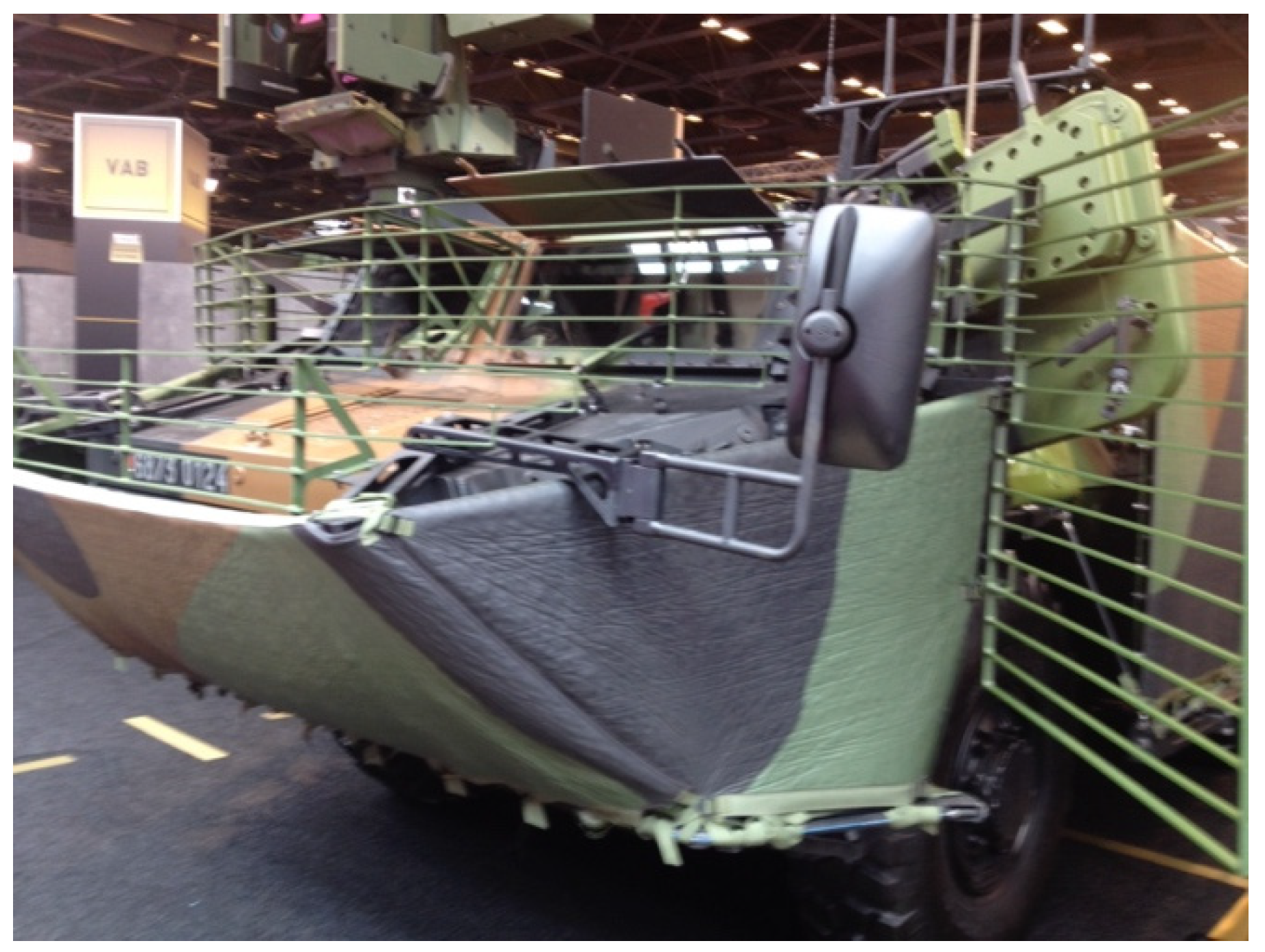
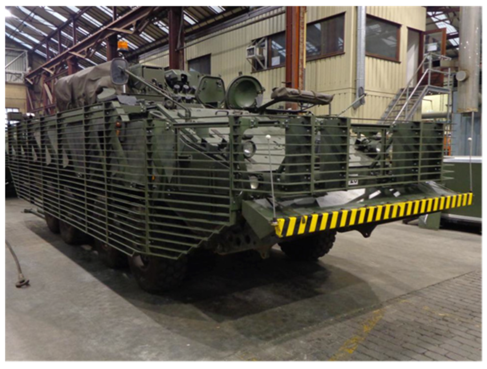
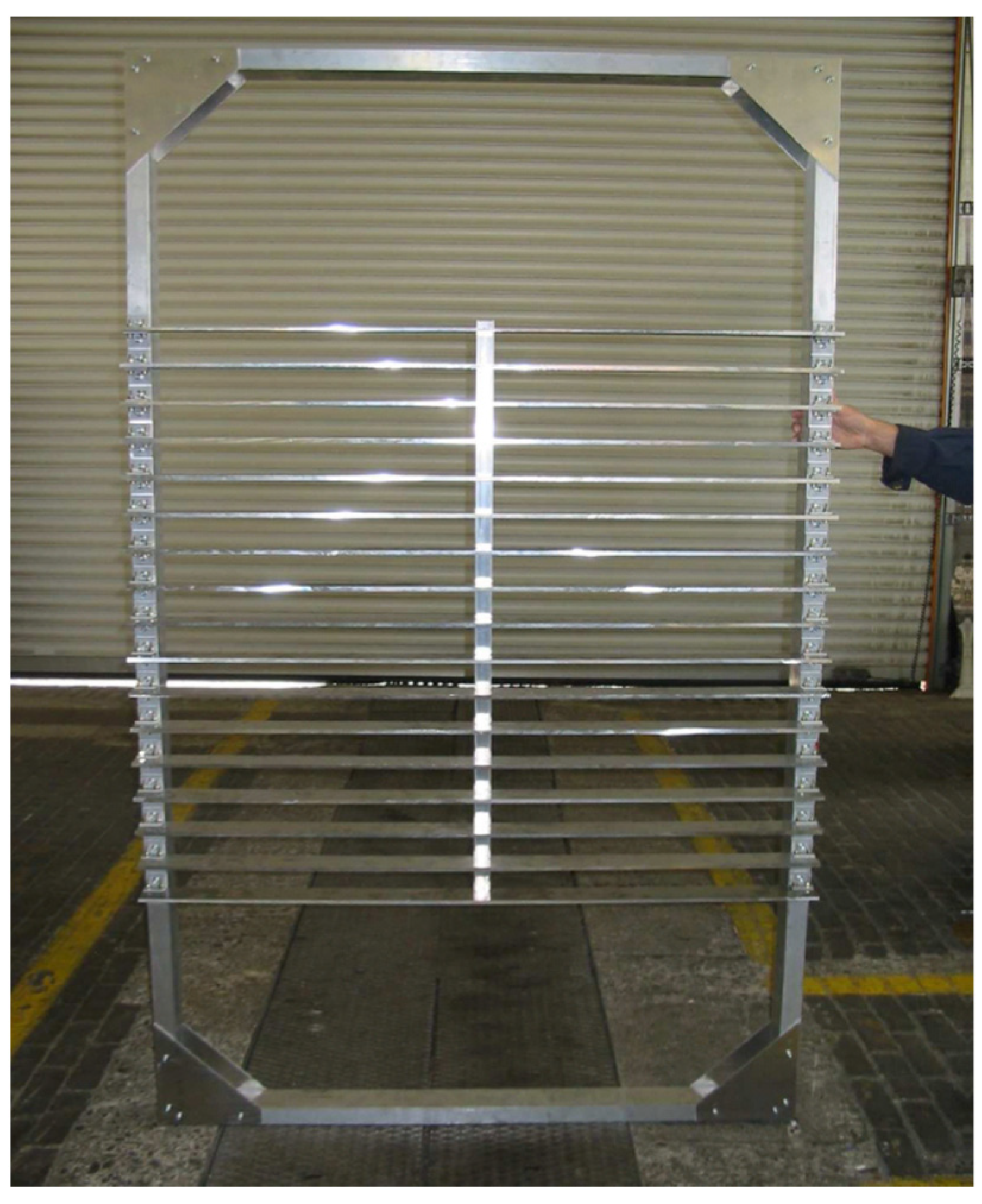
In the following sections, the most common technical solutions for a cage armour system will be discussed in more detail, describing the typical geometries and used materials.

3.1. Bar Armour

Likely being the simplest cage armour system, bar armour consists of attaching horizontal bars to the platform to protect it against shaped charge projectiles, as illustrated in Figure 5. Although round bars are often used, a number of nations have used square bars to increase the damaging effect of the bars on the incoming rounds. In order to have sufficient stiffness and resistance, 12.7–19.0 mm (0.5–0.75 in) diameter steel bars are often selected as the basis for a bar armour system. This generally also makes the system more ‘forgiving’ whenever the platform hits another object (trees, rocks, buildings…). These diameters normally also permit the user of the vehicle to use the bar armour to climb on the vehicle, as the normal stepping and climbing points are no longer accessible once a cage armour system is mounted onto the vehicle.

3.2. Slat Armour

Most cage armour systems are built up using metallic slats or lamellae (Figure 6). The use of such geometry maximizes the stiffness and the resistance of the cage armour against an incoming projectile (second design principle), while minimizing its vertical cross section (fourth design principle). This, however, comes at a cost: the horizontal surface is increased, lowering the performance for higher vertical impact angles (see Section 5.2), and the reduction in vertical stiffness no longer allows climbing onto the slat armour, while also making it more vulnerable to damage during use.
Typical slat dimensions show a width of 40–60 mm and a thickness of 6–8 mm. Slats can be made out of aluminium or steel, with aluminium giving considerably lighter yet more expensive solutions.

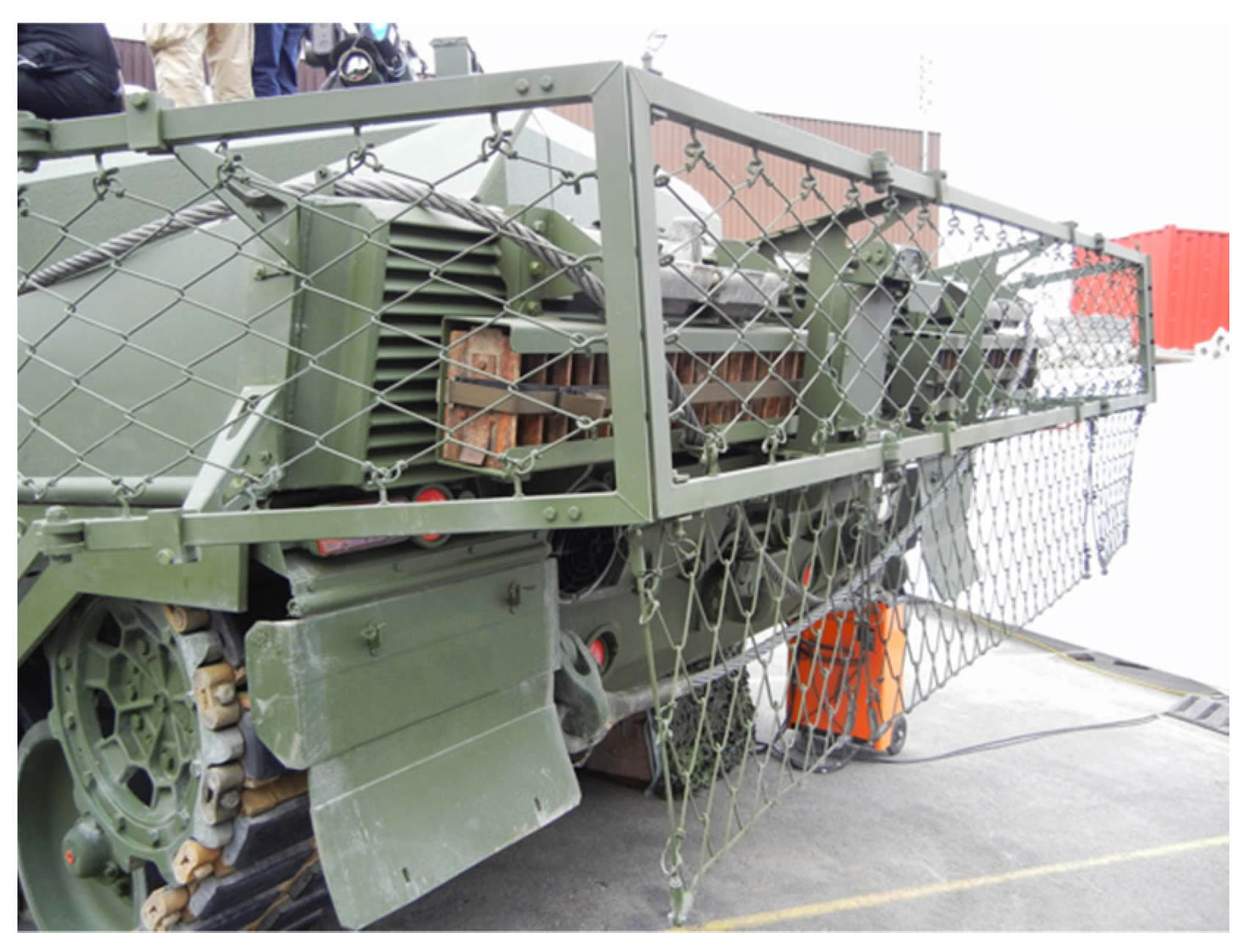
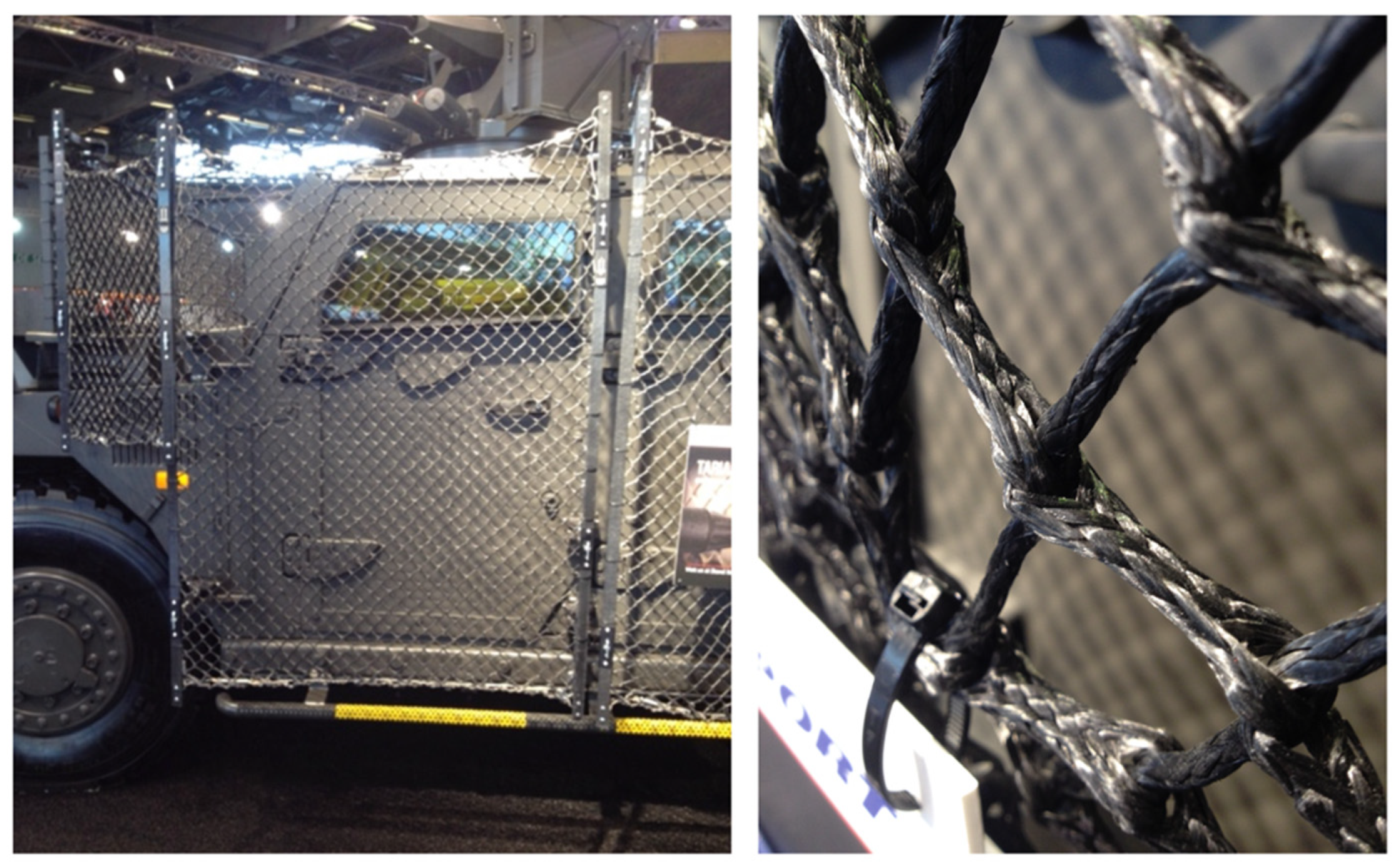
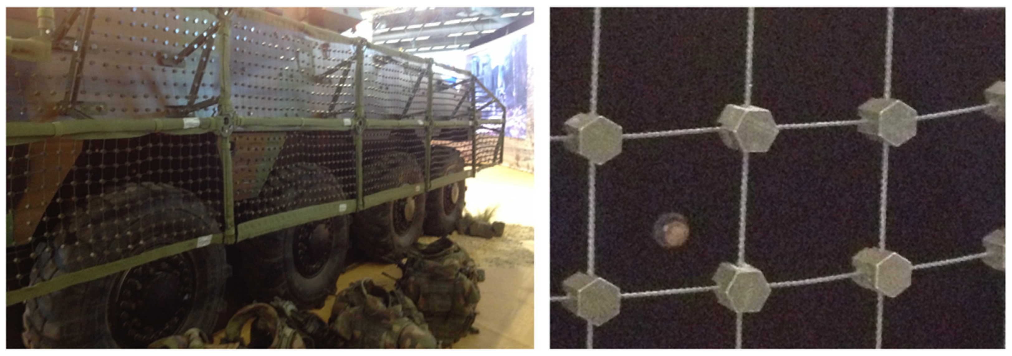
3.3. Net/Mesh Armour

A very low-weight cage armour system can be achieved using a high-strength net or mesh as the functional component of the system [12]. Two material solutions have been extensively used for cage armour systems, being, respectively, high-strength steel nets (Figure 7) and high-strength polymeric fibre nets (Figure 8).
High-strength steel nets are produced (as the name implies) from high-strength steel fibres woven together to form a mesh structure. In the case of a metal mesh, relatively high-pretension is allowed on the net, as metals tend to have similar resistance in tension as in shear.
This is different for a net based on high-strength polymeric fibres. As these fibres have normally been optimized for maximum tension along the fibre direction, their shear resistance in a direction perpendicular to the fibre direction is limited. Due to this, the pretension on a polymeric fibre-based net solution should not be too high, as this will not allow the initial shear loading of the impacting projectile to be transformed into a tensile loading along the fibre direction. The latter is achieved by permitting an important out-of-plane movement of the net, and due to this, the standoff required for a polymeric fibre-based net solution tends to be larger than for any other system, reducing the spatial effectiveness of this solution. This also has a consequence that the final short-circuiting of the detonation chain of the incoming projectile is not achieved by shearing off of part of the outer cone, but rather by constriction of the complete outer cone when it is passing through one of the mesh openings. This has a beneficial effect on the effectiveness of such a system, as this allows a small delay for the component of the cage armour, i.e., the polymer meshes, to move ‘out of the way’ before sufficient force is built up on the piezoelectric element to trigger it, considering the typical low density of polymeric fibres, in cases where the piezoelectric element impacts directly on the fibre. Such a sequence of events is illustrated in Figure 9. Nevertheless, for an impact directly onto a fibre, especially in the neighbourhood of a knot in the mesh, there is a probability that the piezoelectric element will be triggered just as with any other cage armour system. A significant drawback of this system is its limited service time and shelf life, as the polymer fibres change their properties due to ageing, especially when exposed to different meteorological conditions. Due to this, its performance can typically not be guaranteed for longer periods, even if stored in a controlled environment.

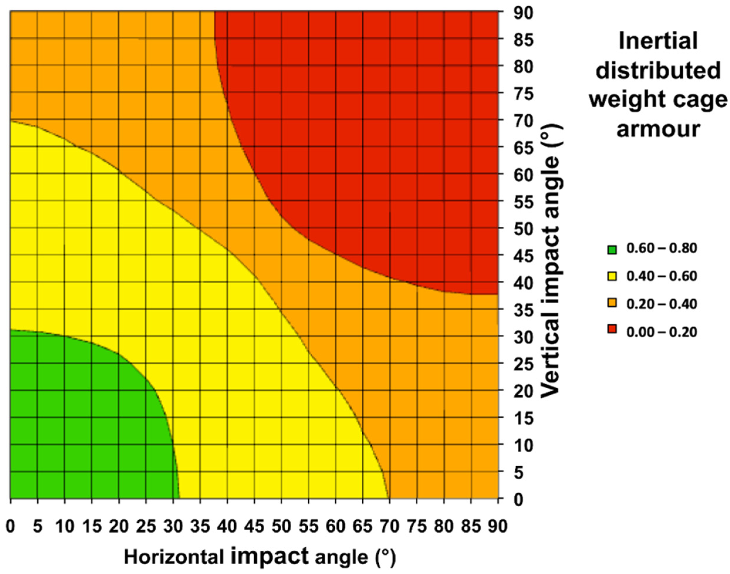
3.4. Inertial Distributed Weight Armour

The most recent addition in the range of different technical solutions for cage armour consists of an array of suspended small masses (nodules) in a plane parallel to the vehicle hull (Figure 10). The idea of this system is for the suspended masses to have sufficient inertia to deform an impacting projectile sufficiently to cause a short-circuit [13,14]. To suspend these masses in an array parallel to the vehicle hull, they are typically attached to a polymeric fibre-based net or a polymer sheet in a square or hexagonal pattern. The fibres and sheet material have normally been tuned in such a way that they offer sufficient resistance to keep the attached masses in their position during normal use of the vehicle but will readily break away should the piezoelectric element of the projectile impact directly onto one of these fibres or the sheet material. Although these systems have high mass efficiency, a significant drawback of these is again their limited in-service and shelf life, as the polymer fibres and sheets change their properties due to ageing, especially when exposed to different meteorological conditions. The efficiency can, however, be increased by using high-density material (e.g., tungsten) for the nodules, as this will minimize the dimensions of the nodules for a given effect on the projectile.

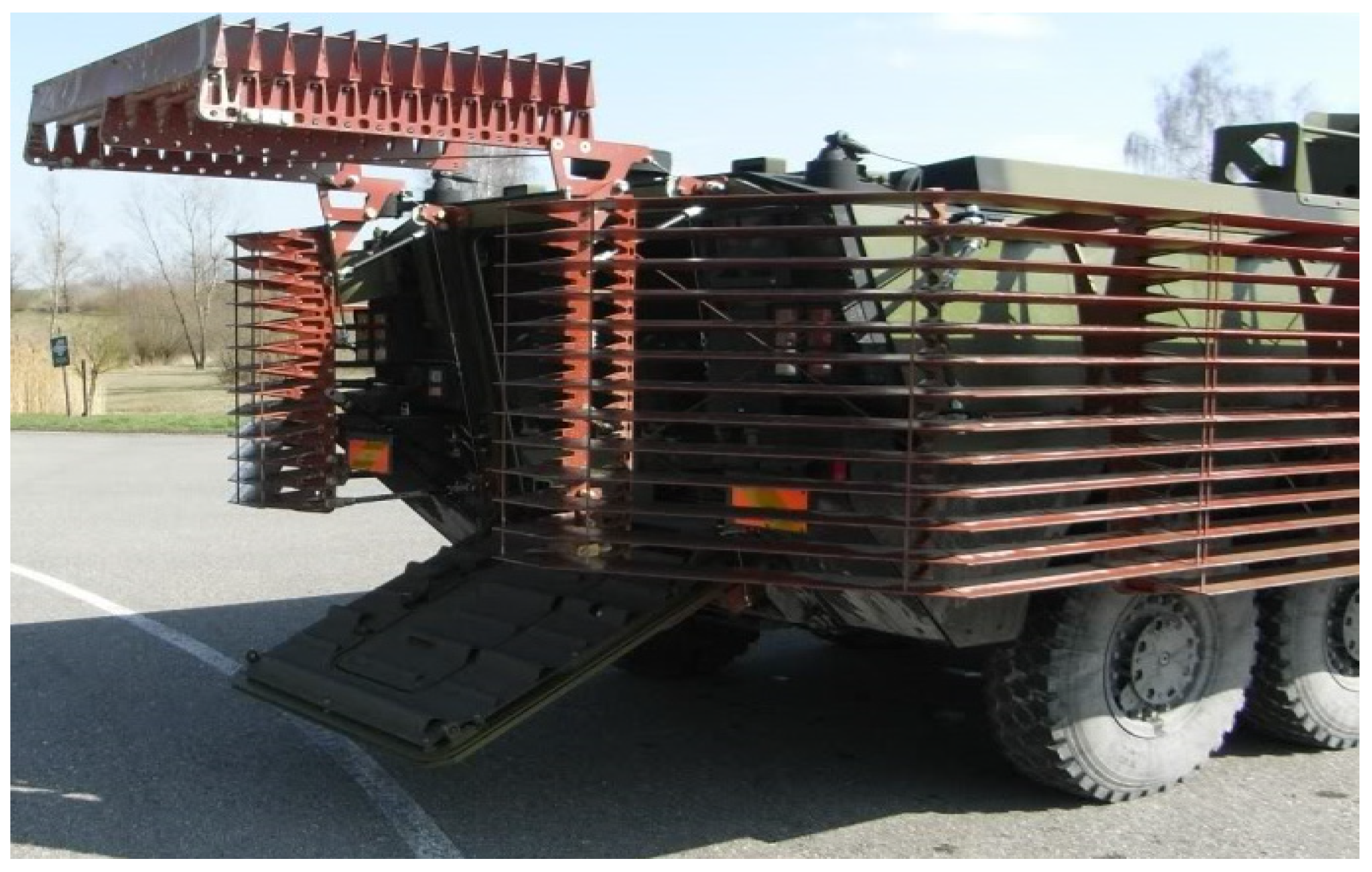
3.5. Special Versions

A number of cage armour systems have also been developed for specific applications or in search of specific properties but are not as widespread as the previous systems. A number of these specialized systems are briefly described in the following subsections.

3.5.1. Spike Armour

A similar concept to the inertial distributed weight system, yet acting on the structural resistance instead of the inertia effect, is so-called spike armour. The cage armour here consists of outwardly oriented metal spikes that will pierce the projectile body upon impact on the cage armour [15]. This will again cause a short-circuit of the detonation chain but will also severely damage the cone of the shaped charge. The concept was apparently already experimented with by South Africa in the 1970–1980s, yet the spike armour tended to stick onto the vegetation the vehicle, equipped with the spike armour, was riding through, effectively turning it into a ‘moving haystack.’ This problem was only solved relatively recently by the development of polymer cover sheets for the spike armour that would keep the vegetation from interacting with the spike armour, but with sufficiently low resistance not to trigger the piezoelectric element of the projectile upon impact on the cover sheet.

3.5.2. Steel Cable Armour

A number of countries also experimented with high-strength steel cables attached to a frame and put under an angle, typically in front of the vehicle windscreen. This not only helped in improving the visibility for the driver but by attaching the cables top and bottom to the angled frame, also helped in causing the projectile to only graze the cage armour and bounce off into the air again, especially for shots aimed directly at the front of the vehicle (which is the preferred tactical firing technique with the RPG-7 weapon system). The efficiency of this solution seemed, however, to be limited compared to the other technical solutions. Nevertheless, serrated flexible thin slat solutions with similar flexibility as cable solutions have recently been introduced that have the same effect as regular slat armour, but that easily fold and bend without damage, e.g., when driving to thick vegetation [16].

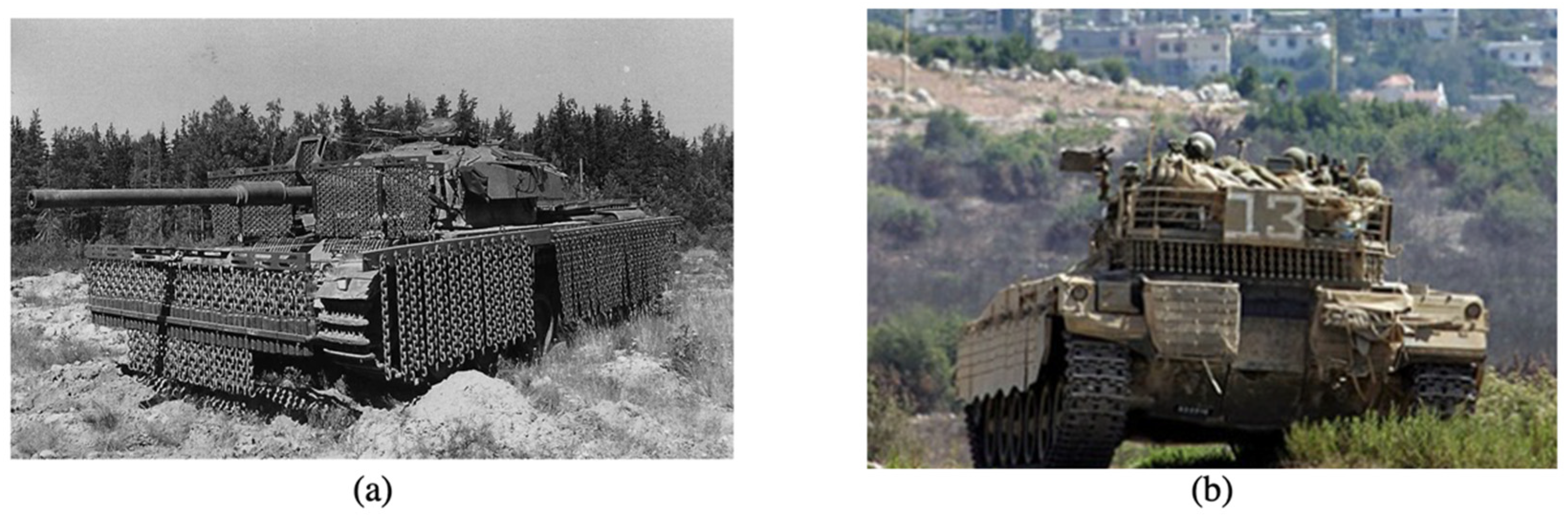
3.5.3. Chain/Ball Armour

Similar to the steel cable armour, a number of armoured vehicles used vertically suspended chains to either short-circuit or damage the projectile before impacting the hull of the vehicle. In order to assure sufficient interaction between the chains and the projectile, the inertia of the chains is typically increased by attaching a heavy ball at the end of the chain. Although the efficiency is generally limited due to the relatively small amount of free space in between the chains, the combination of possible short-circuiting of the detonation chain, damaging the shaped charge and increasing the standoff distance has led to the operational use of chain/ball armour, specifically on main battle tanks (Figure 11) where a fixed cage armour system would interfere with one of the functionalities of the vehicle (e.g., under the turret bustle of a tank to allow turning the turret without interference with the vehicle hull).

4. Experimental Validation of the Geometrical Efficiency Calculation

4.1. Metal-Based Cage Armour Systems

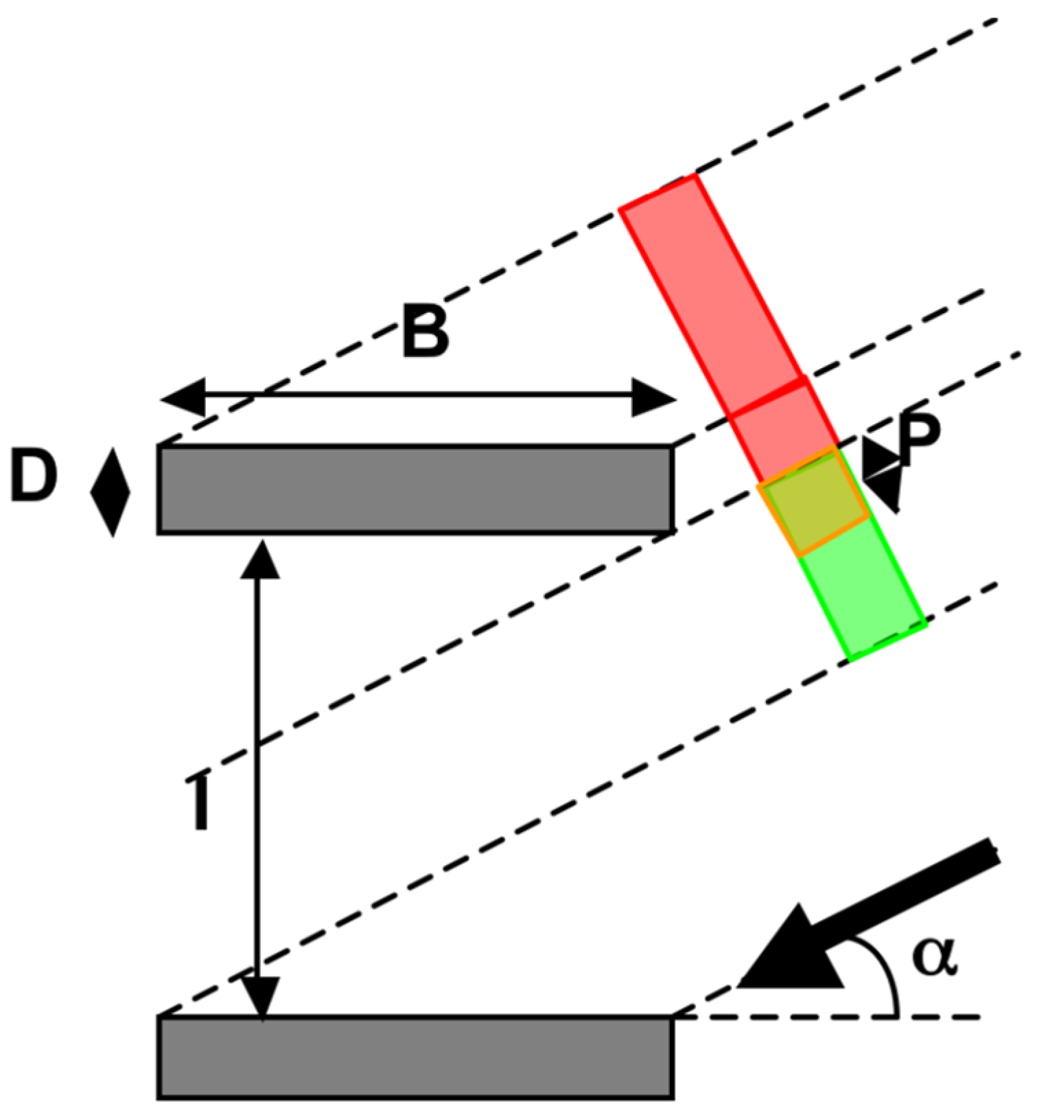
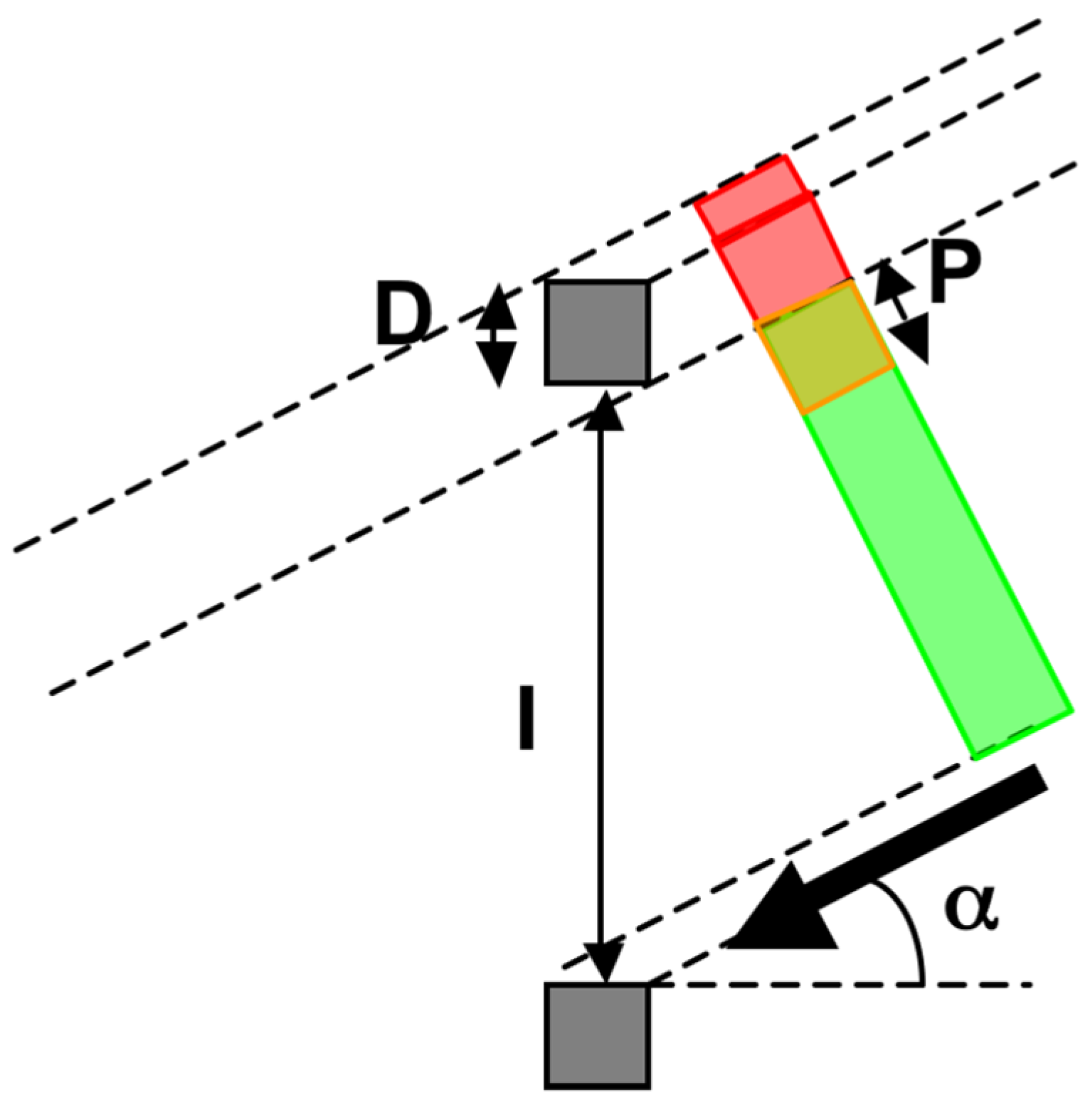
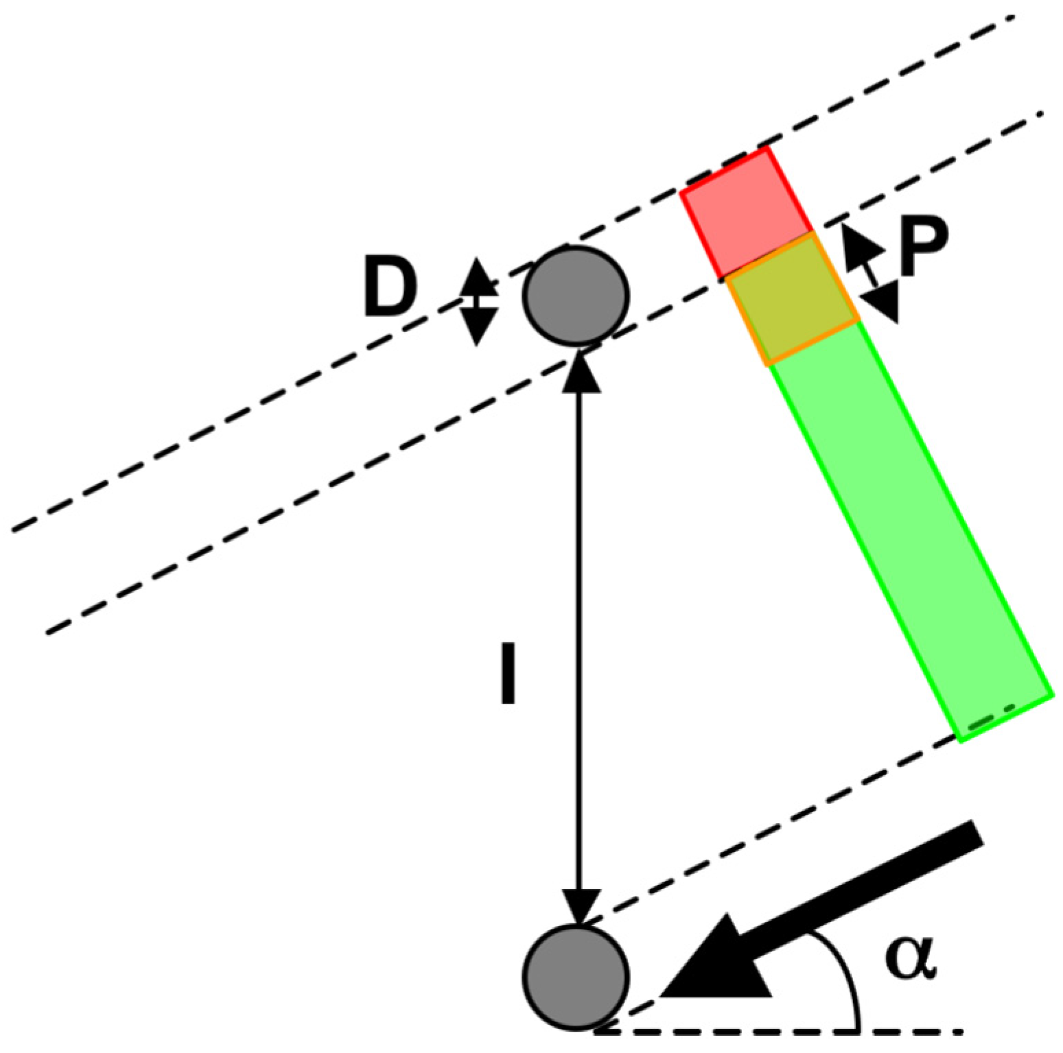
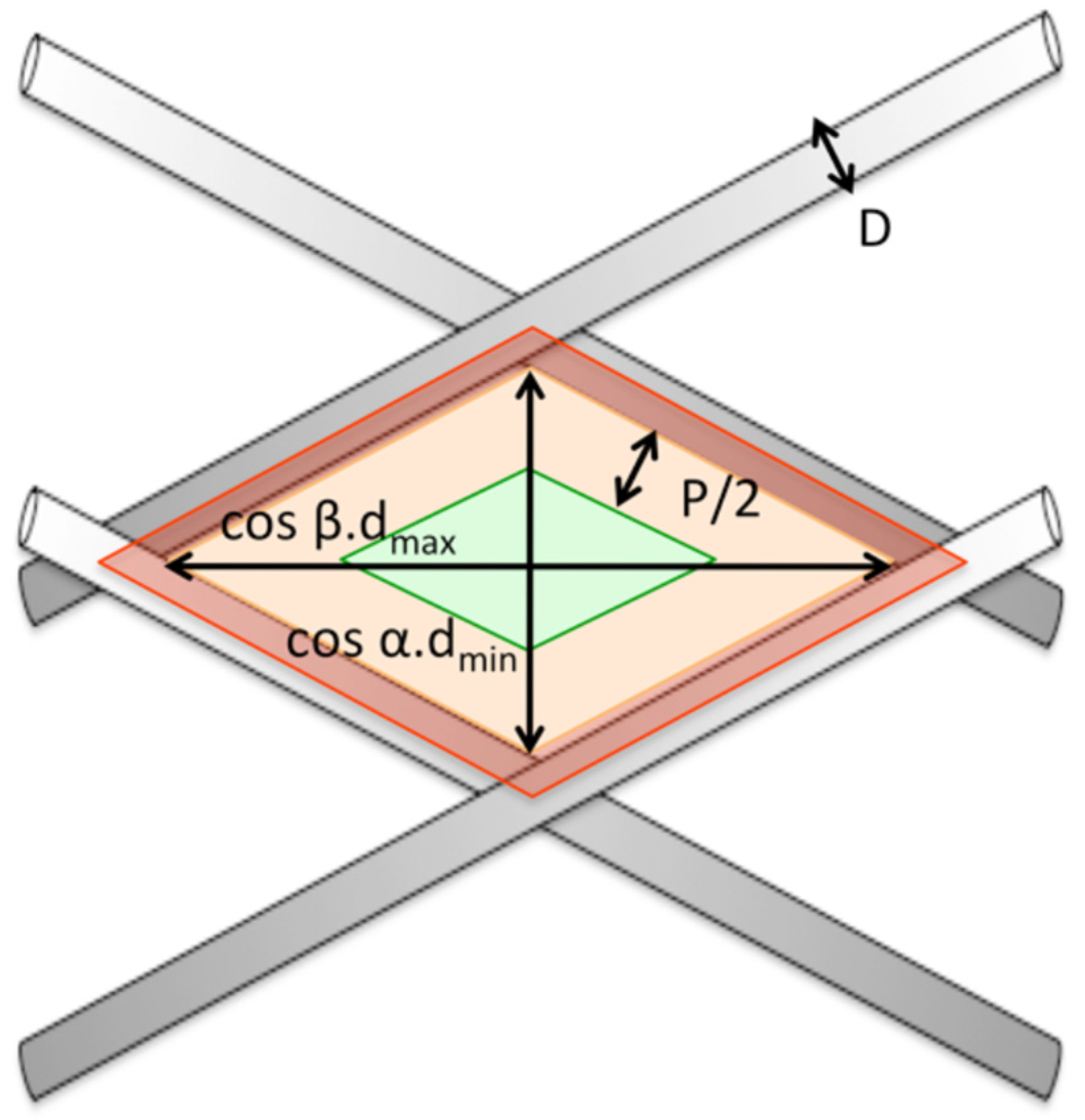
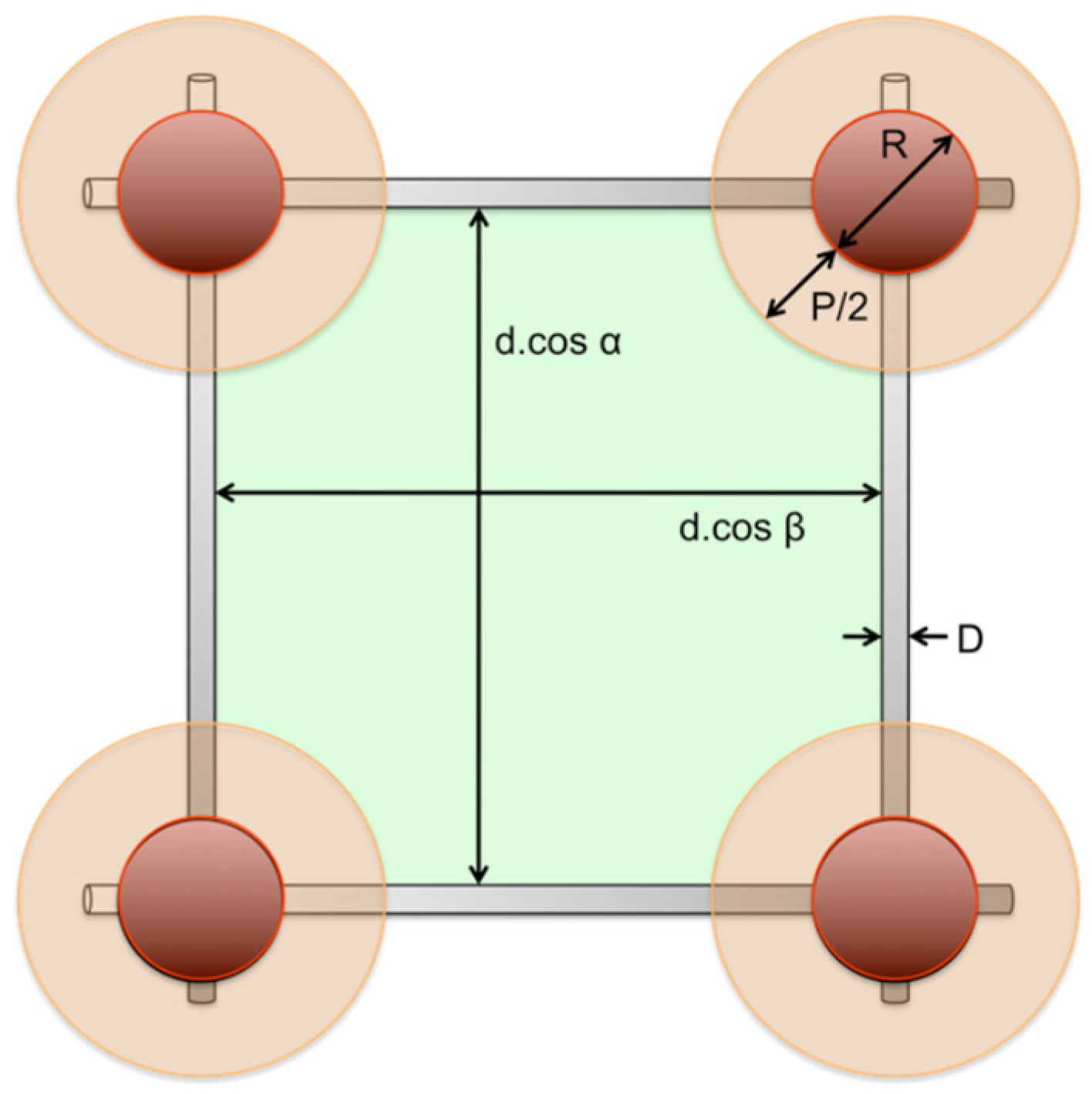
4.1.1. Geometrical Analysis

Determining the efficiency of a cage armour system is, for all metal-based systems fairly straightforward, at least approximatively. It theoretically suffices to determine the probability that the piezoelectric element will fall in between the components of the cage armour, while the projectile body comes into sufficient contact with these components to cause the required short-circuit in the detonation chain. Although small variations will exist depending on the exact interaction between the projectile and the cage armour system, a fairly accurate estimate can be based solely on a geometrical analysis. This approach has been followed by other research groups [10], yet without experimental validation. The latter will be provided in the next subsection of this paper.
The probability of correct functioning of the cage armour will vary as a function of vertical (elevation) and horizontal (azimuth) impact angle and with the specific threat (projectile) that is considered, as the dimensions of the projectile subcomponents change depending on the projectile type. Unfortunately, the perceived geometry of especially a net solution from the standpoint of the projectile will change considerably whenever the trajectory of the projectile leads to a compound (i.e., azimuth and elevation different from zero degrees) impact angle. For instance, a square mesh will transform into a parallelogram mesh when viewed from a compound angle. Determining rigorous analytical solutions for compound impact angles, is hence not as straightforward as one would initially think. Nevertheless, first-order analytical approximations can be relatively easily developed by assuming the influence of azimuth and elevation to be independent. These approximations are relatively accurate up to 60° compound impact angles. Although for higher impact angles more important deviations may appear, the more complex cage armour systems, e.g., based on nets, have an efficiency close to zero anyway due to the too-small remaining presented free spacing between the wires. Approximate mathematical expressions for the different considered cage armour systems are given in Appendix A.
It is important to notice that the determined expressions to calculate the cage armour efficiencies also do not take into account the possible presence of mountings or attachments needed to fix the cage armour system to the vehicle. Any presence of an item that might trigger the warhead before it can be short-circuited will lower the actual efficiency compared to the theoretically derived efficiency.

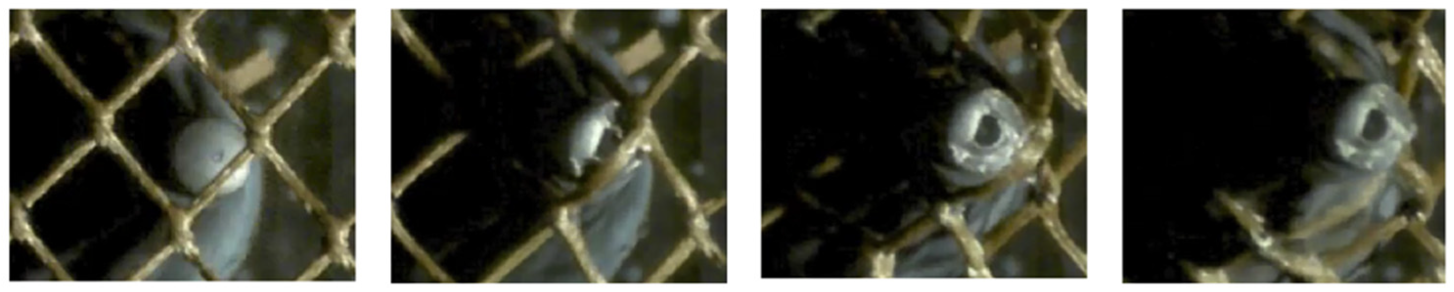
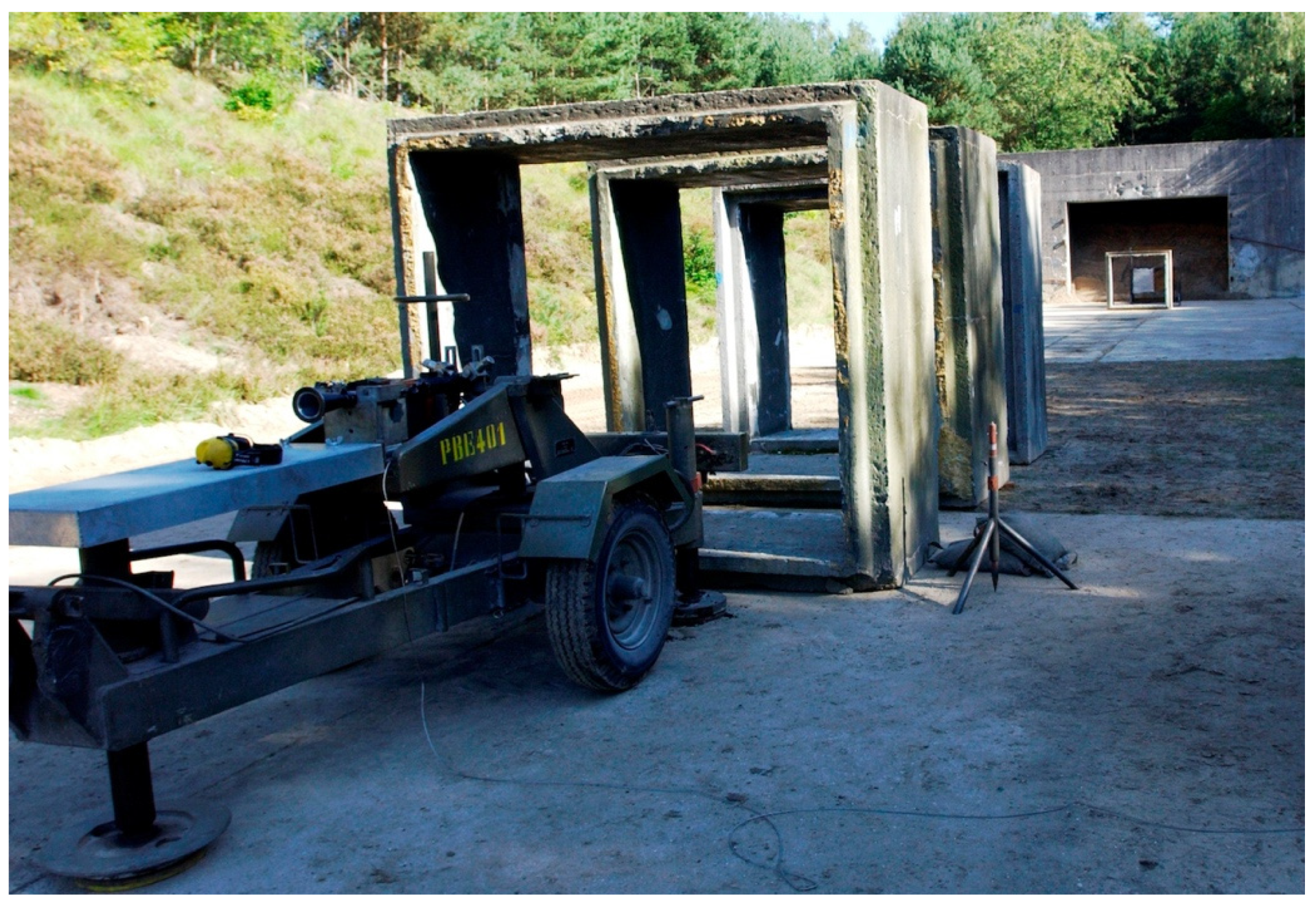
4.1.2. Experimental Validation

The previously developed mathematical expressions can be validated using experimental data. Due to the confidential nature of actual cage armour performance, only limited data are available that can be used to show the validity of the developed expressions. In the following sections, the results of experimental firings on four non-fielded experimental cage armour solutions (two lamellar systems and two net systems) will be compared to the theoretical results.

Case A: Lamellar Slat Armour

Two lamellar cage armour systems were tested against the PG-7 warhead. The two systems were composed of aluminium slats with respective thicknesses D of 6 mm and 8 mm (must be as thin as possible compared to the effective diameter P of the piezoelectrical element) and relative spacing I between the slats of 55 mm and 47 mm (see Table 1 for all relevant properties). These spacings were selected to be sufficiently smaller than the effective diameter Ceff of the PG-7 warhead to avoid non-proper functioning of the cage armour system. A regular RPG-7 launcher mounted on a gun carriage was used to fire at the sample targets (consisting of 1.5 m × 1.5 m prototype slat armour systems as shown in Figure 12). All impacts were made at 0° obliquity (NATO impact angle convention) at a shooting distance of 50 m. The impact point in reference to the slat armour was varied randomly in order to obtain a true sample (i.e., statistically independent testing) of the slat armour efficiency. The complete setup is shown in Figure 13.
Twenty-six shots were done on the 6 mm slat solution, while 25 shots were done on the 8 mm slat solution. The experimental results showed excellent agreement with the theoretically calculated efficiencies, as shown in Table 2.

Case B: Steel Fibre-Based Net Armour System

Data were also obtained on a steel net armour system against the PG-7 and PG-7L projectiles. The latter is similar in concept to the original PG-7 warhead but is equipped with a shaped charge cone with larger diameter (84 mm, giving a maximum projectile diameter of 93 mm). The net was built out of 4 mm thick high-strength steel wire with a diamond-shaped mesh. The horizontal diagonal of the diamond-shaped measured 192 mm, whereas the vertical diagonal measured 110 mm. Although most data concerns perpendicular impacts, a limited number of shots were also performed with both projectiles for a 45° azimuth impact angle. However, due to the very limited number of shots, the statistical value of the experimental results is limited. The different considered configurations (cases) are given in Table 3.
As in this case, the mesh size is large enough to let the projectile pass unaltered for certain impact locations; the effective diameter Ceff must be determined. As a first approximation, Ceff was for this case, considered to be equal to the cone diameter of the shaped charge, being 75 mm and 84 mm for, respectively, the PG-7 and PG-7L warhead.
The results for the different cases are shown in Table 4. It is clear that the model is able to reproduce the experimental trend for the two cases where a sufficiently large number of projectiles were shot to give a statistically valid sample size. The fit of the model could actually be improved by fitting the values for Ceff, as the latter is an indirect measure of the intensity of the interaction between the cage armour and the incoming projectile, which will vary with the actually considered cage armour system and type of projectile. Although the differences between the theoretical and experimental probabilities are larger for the angled shots, the model is able to capture the relative performance difference for the two considered projectiles. As already mentioned, the experimental sample size is, however, considered to be too small to be representative of the actual performance of the system.

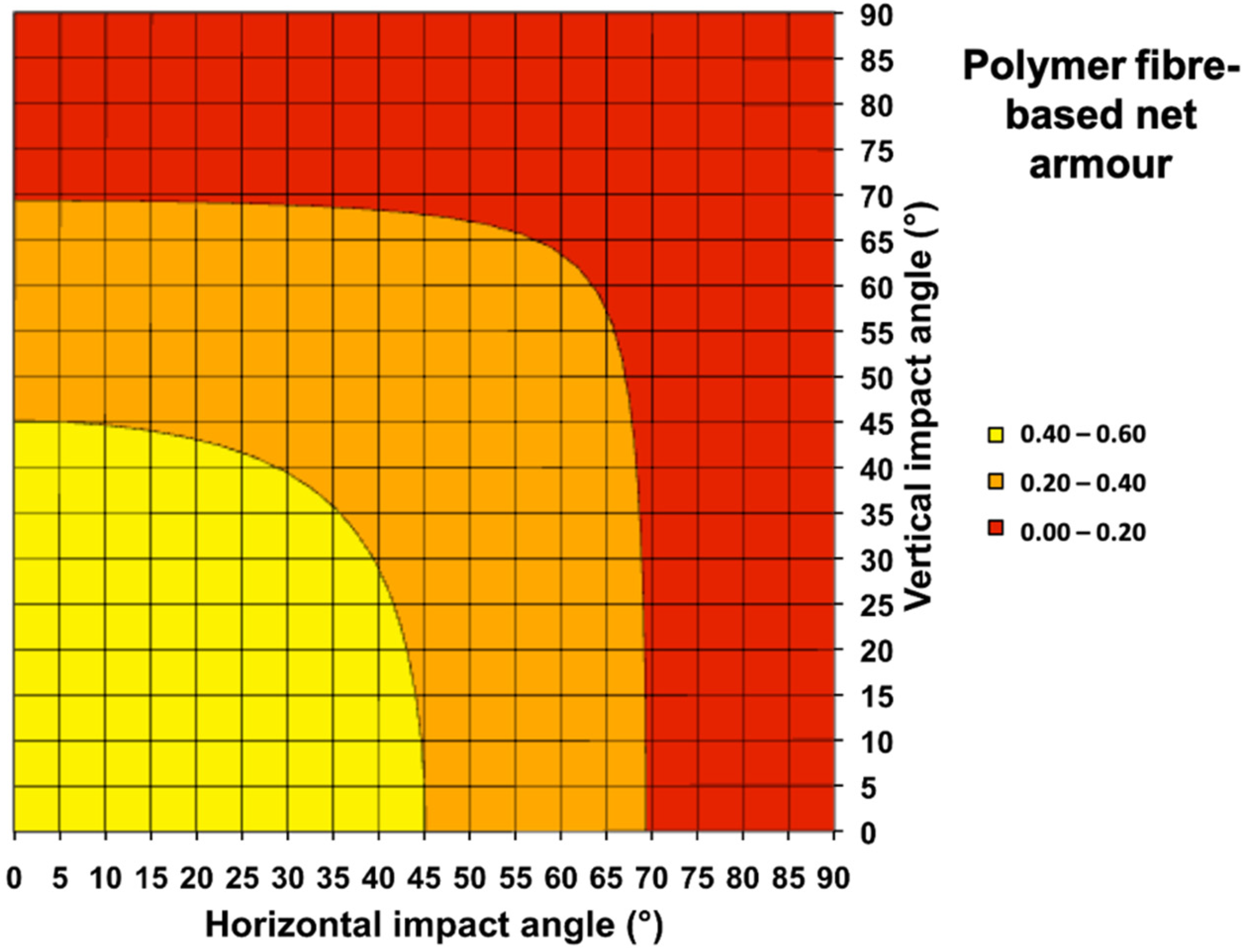
4.2. Polymer Fibre-Based Net Armour System

The efficiency of the net is again given by the probability that the piezoelectric fuse of the warhead does not hit on the part of the net that will have sufficient resistance to trigger the detonation chain. Although this is similar to what was seen with other metallic cage armour systems, a straightforward determination of the efficiency of the net as a function of impact angle, such as for other cage armour systems, is not as evident. This is due to the possible slipping of the net over the fuse, even for a direct impact of the fuse on the part of the net. Nevertheless, it is clear that in the cases where the net does not function correctly (initiation of the shaped charge), this is again due to a too violent interaction of the fuse and a part of the net upon initial impact. This means that the net can still be modelled using a geometrical approach, such as in the case of other cage armour systems, but that the initial configuration and areal density of ‘hard points’ (which in other systems is any structural part of the system) is unknown. Assuming that the configuration and areal density of ‘hard points’, which is any point of the net giving sufficient resistance to trigger the fuse of the warhead, are constant (e.g., from one net to another, independent from the exact mounting conditions) and that these can be considered as being ‘spherical’ in nature (at least as a first approximation), then the efficiency P t h e o , α of the net as a function of impact angle α can be described by:
P t h e o , α = P t h e o , 0 ° · c o s α  
In order to verify this, an experimental campaign was performed were, in total, 58 PG-7M projectiles were fired against a polyethylene fibre-based net system. Thirty shots were done perpendicular to the net; the remaining 28 were done with a 45° impact angle. Although the 45° impact angle was in the vertical plane, a 45° impact angle in the horizontal plane would have given similar results due to the square meshing of the considered net system.
The results for the two configurations are given in Table 5 and clearly indicate the validity of Equation (1). Just as for a metal-based net armour system, the efficiency of a polymer fibre-based net system will vary both with azimuth and elevation of the incoming projectile.
It is important to note that the aforementioned analysis made some important assumptions.
One of the factors that was not taken into account during this analysis but that may have a major influence on the outcome of the tests is the sensitivity of the fuse of the warhead and the variability of this sensitivity from one projectile to another or from one manufacturer to another. Experimental characterisation of the fuse sensitivity for different ammunition batches from different manufacturers might give interesting data to elucidate the influence of the sensitivity of the fuse on the net efficiency, but this would require a large experimental campaign outside the scope of this experimental campaign. It can also be noted that as a first approximation, the efficiency of all metallic cage armour systems can be assumed to be independent of the fuse sensitivity.
Next to this, if the ‘hard points’ cannot be considered to be spherical in nature, the projected area of the hard points will vary with the considered impact angle, and the derived mathematical formulation for the angular efficiency will be more complex.

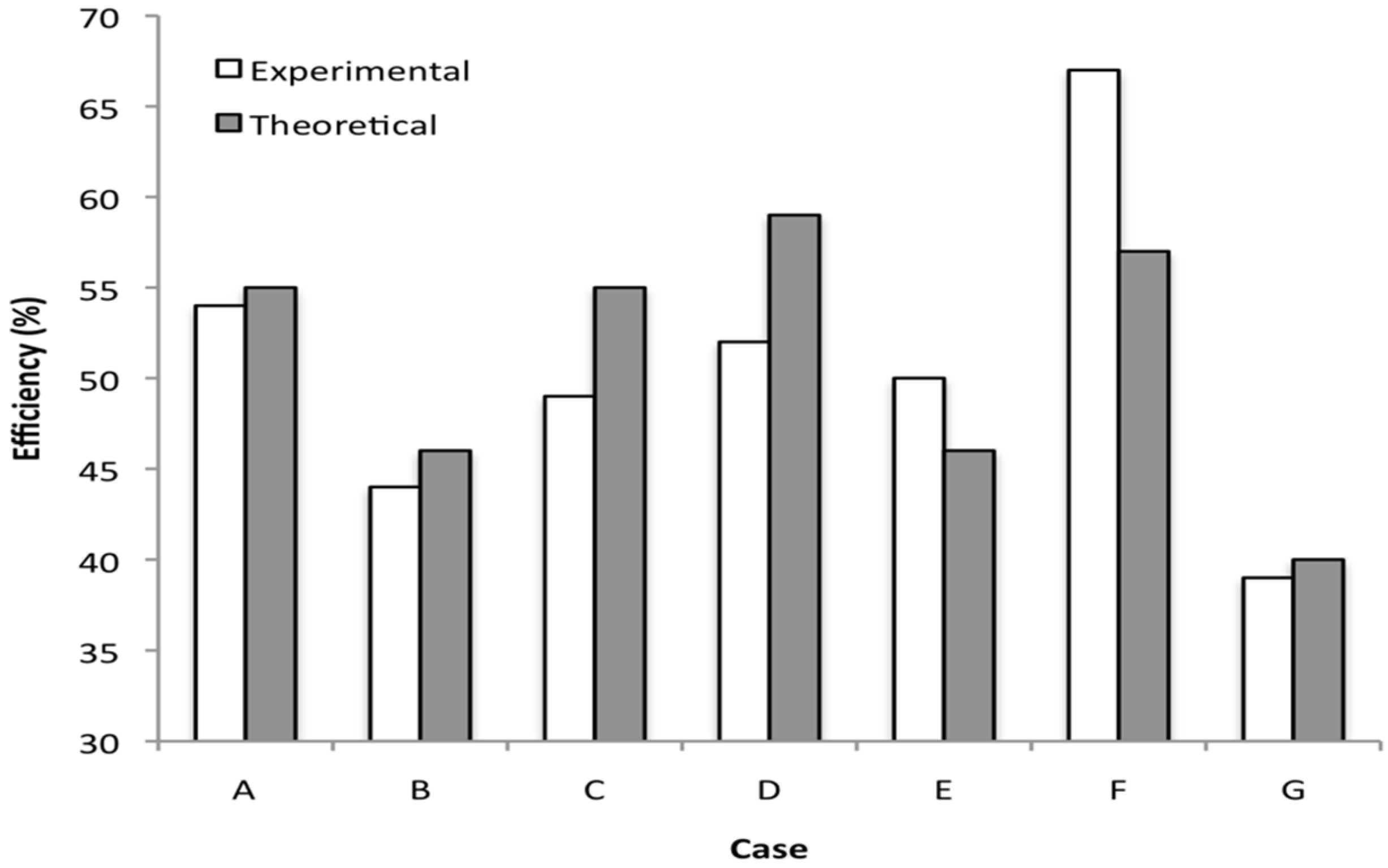
4.3. Final Comparison Experiment vs. Modeling

Figure 14 finally shows an overview of all considered experimental efficiencies and the calculated theoretical efficiencies. It can be concluded that the proposed geometrical analysis is indeed able to predict at least the tendencies in efficiency regarding the different cage armour systems and taking into account the impact angles in both the horizontal and the vertical plane. As already stated before, the models can be improved by fitting the parameters of the projectile (effective diameters of the projectile and the piezoelectric element) to the experimental data. In this way, accurate efficiency estimations can be done for a given cage armour system.

5. Comparison of Different Cage Armour Systems

In the following subsections, generic designs for different cage armour systems will be compared based on their ballistic and mass efficiency, using the equations developed in Appendix A and validated in the previous Section 4 using experimental data. The considered systems are notional systems and not actually fielded systems for matters of confidentiality and security, but are nevertheless representative of the relative performances of the different operational cage armour systems.

5.1. Description of the Considered Cage Armour Systems

Seven different systems were considered in total. The systems included two slat armour solutions (one with steel slats, one with aluminium slats), two bar armour systems (square and round steel bars), two net systems (steel fibre-based and polymer fibre-based) and one inertial distributed weight system (steel nodules). More details on the considered systems can be found in Table 6. The slat width for the aluminium slat armour (system 2) was selected to give the same stiffness in the horizontal plane for an orthogonal impact as the steel slat configuration (system 1). Although not optimized, the selected dimensions for all systems were based on a PG-7 threat and similar fielded systems.

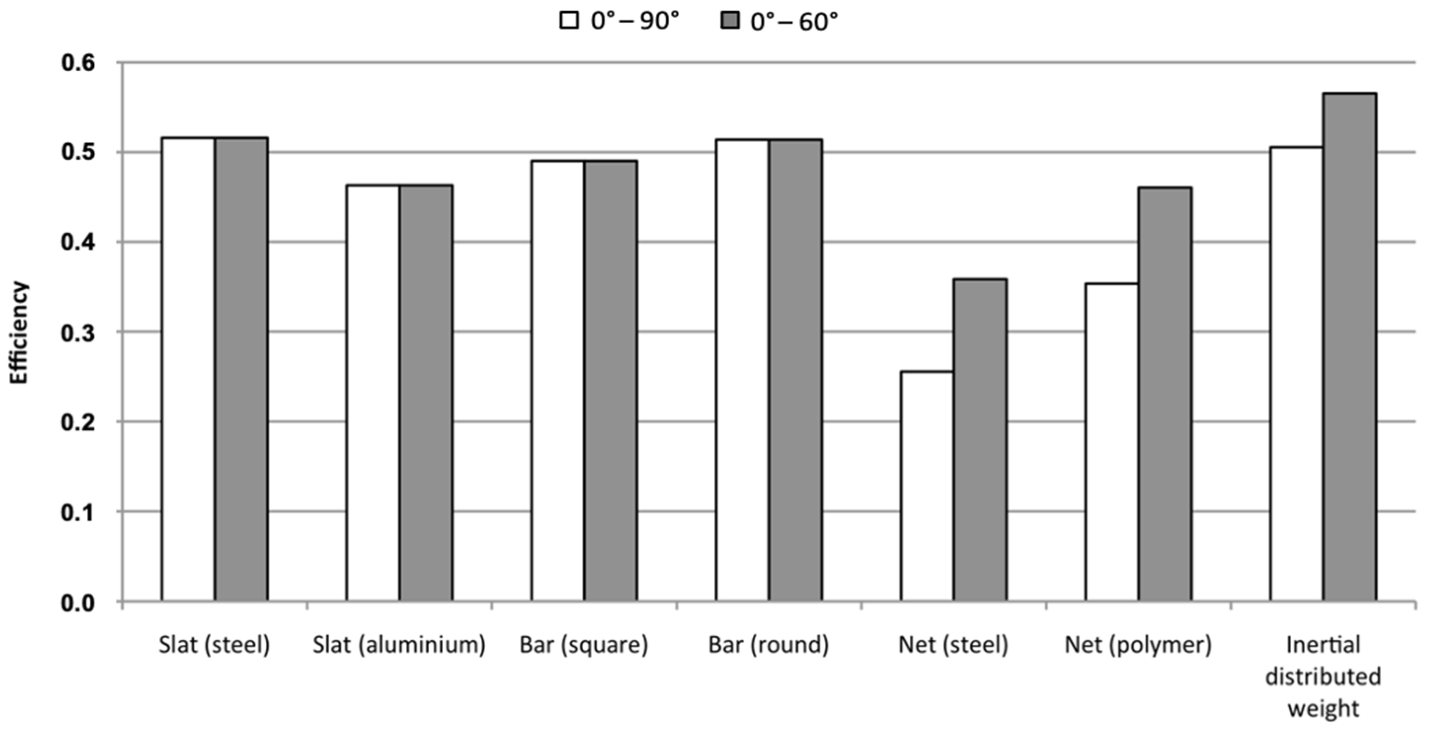
5.2. Ballistic Efficiency Comparison

Using the aforementioned approach, the efficiency of systems 1 to 5 can be readily calculated as a function of impact angle. The considered threat was the PG-7 projectile using the properties of Table 7. As aforementioned, the efficiency of system 6 cannot be determined based on a geometrical analysis only, as there is a possibility for the fibres to slip over the piezoelectric element without triggering the fuse. However, using the experimental results and Equation (1), the efficiency can again be calculated as a function of the impact angle. For system 7, a Monte Carlo approach was partially followed to determine the free space in between the nodules, as the mathematical expressions in Appendix A are only valid in a limited domain of impact angles.
As commonly done [17,18,19], the ballistic efficiency was first calculated as a function of the vertical impact angle only. This will assist in understanding some of the advantages and disadvantages of certain systems. However, an analysis in the vertical plane only is not sufficient to completely evaluate the efficiency of a cage armour system. All real impacts on a cage armour system will also have an impact angle component in the horizontal plane, which will have important consequences for the efficiency of the cage armour systems that have a vertical component (e.g., nets and inertial distributed mass systems) in their structure. Due to this, the efficiency of the different cage armour systems was also calculated for compound impact angles in order to be able to evaluate their performance under more realistic impact conditions.

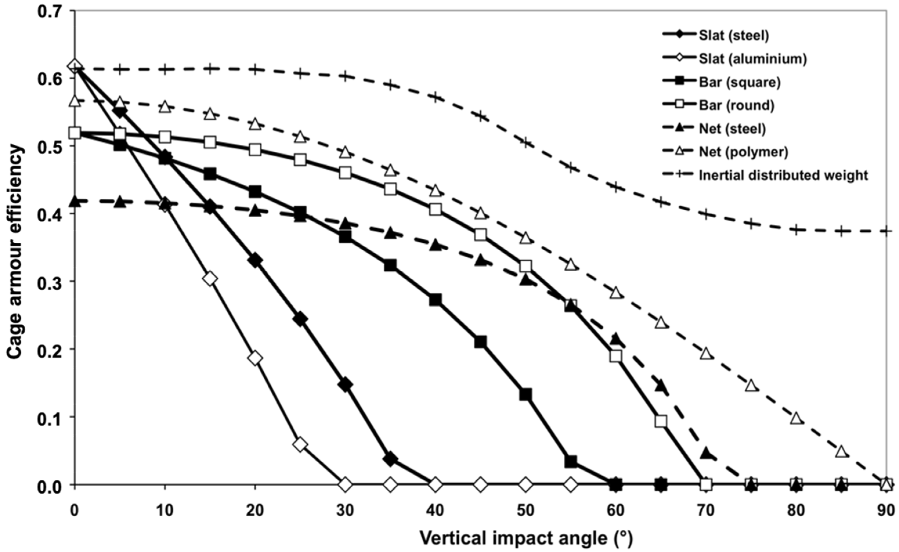
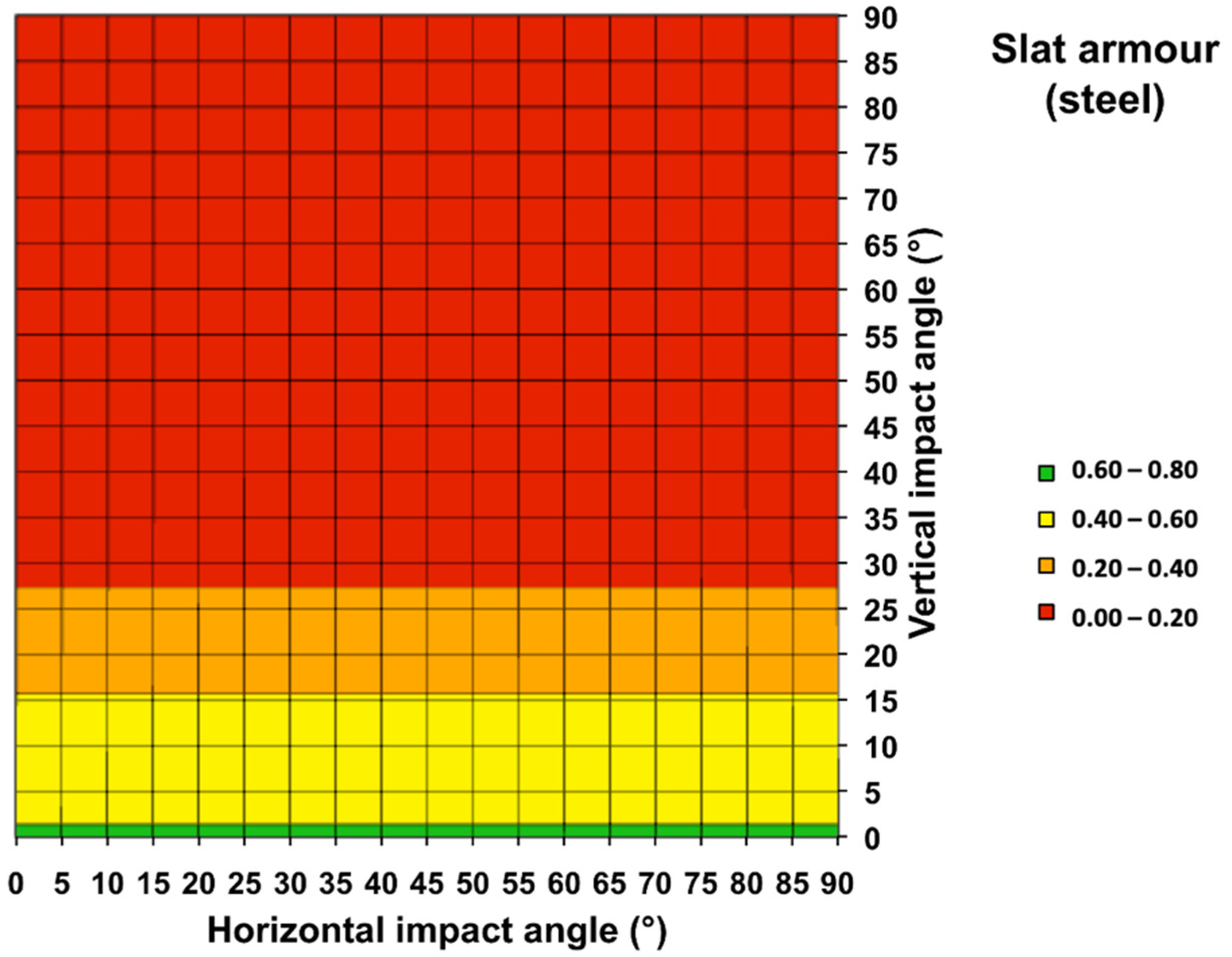
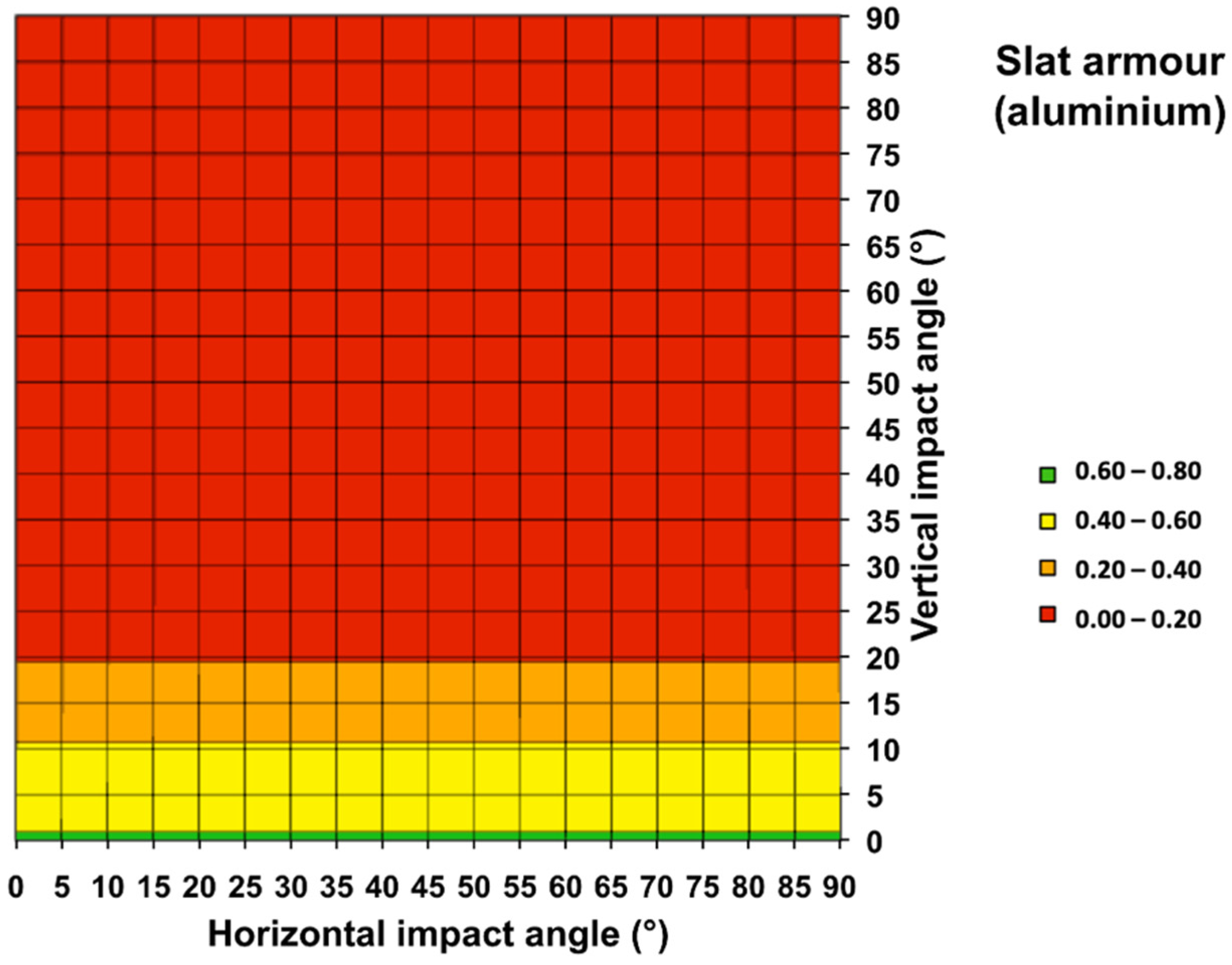
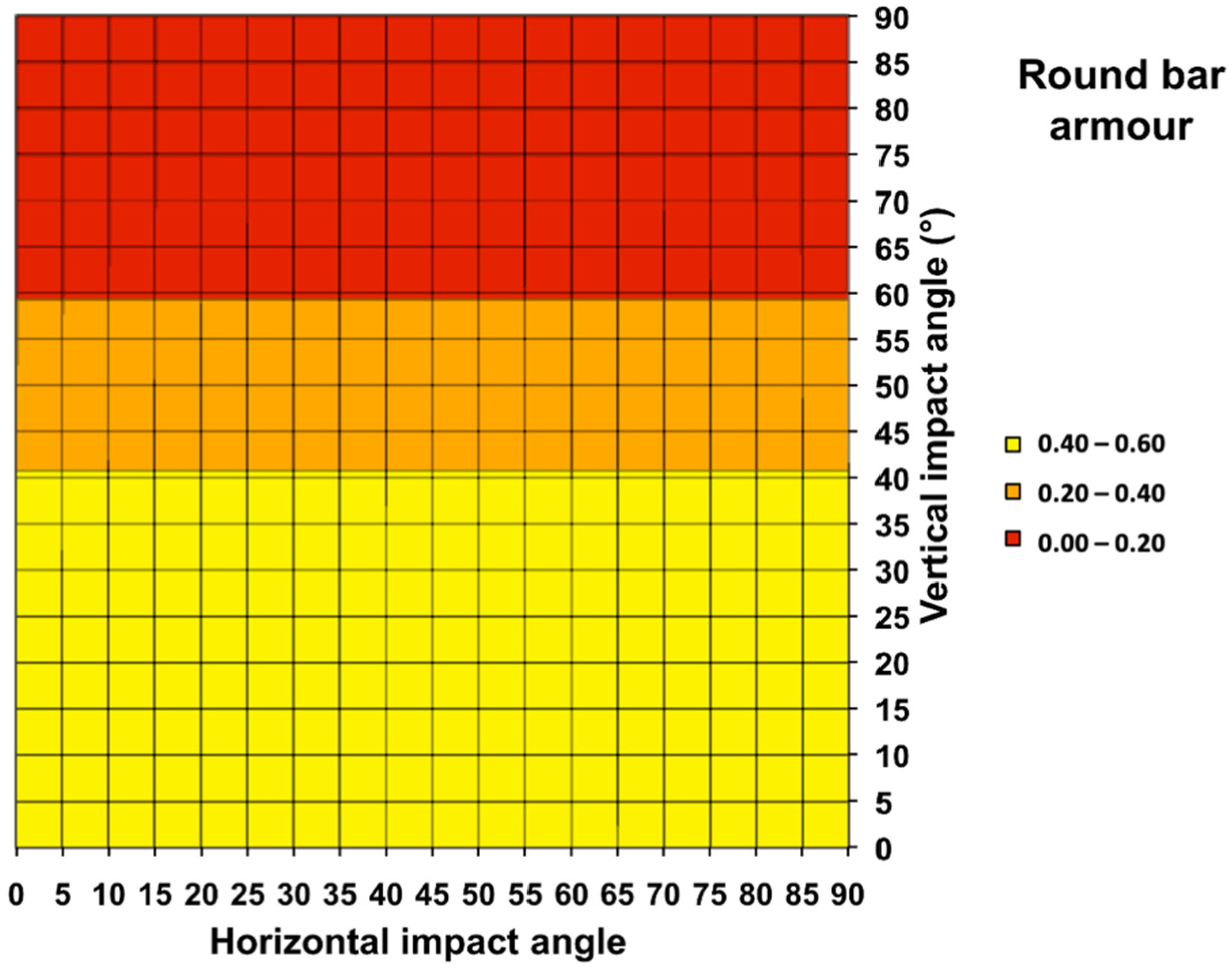
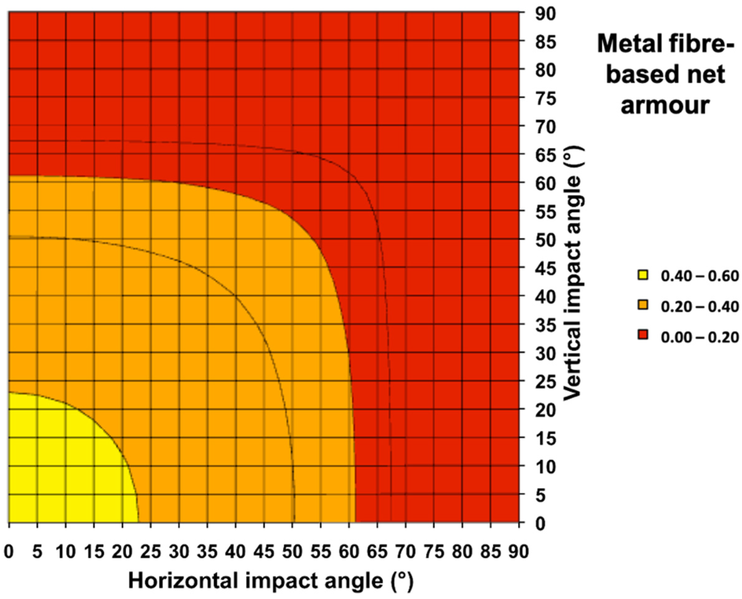
5.2.1. Influence of the Vertical Impact Angle

The efficiency of the different considered cage armour systems as a function of vertical impact angle can be seen in Figure 15. A first observation is that all systems perform relatively similarly for horizontal impacts, with the correct functioning of the cage armour approximately one out of two times. It is evident that the thinnest solutions with only horizontal elements (i.e., slats) have the highest probability of working correctly for vertical impact angles around 0°. This has led a number of countries to introduce V-shaped slats to maximize this probability, as shown in Figure 16. This, however, comes at a much-increased cost and complexity, with only a relatively minor increase in performance. This also further hyphenates the problem of all slat armour systems, namely that with increasing vertical impact angle, the efficiency drops rapidly due to the important width of the slats.
The latter problem is mitigated considerably with the use of a bar armour system but comes with reduced performance for vertical impact angles around 0°. This is due to the fact that relatively thick bars normally have to be used to assure the required stiffness for sufficient interaction with an impacting projectile, while this also helps in increasing the robustness of the system under operational, tactical conditions. It is typically also the cheapest solution, as it does not require any specialized materials, manufacturing equipment or knowhow to be produced.
The net solutions suffer from the fact that they also have a vertical structural component, which reduces their performance for almost horizontal impacts. They, however, conserve this efficiency up to much higher vertical impact angles, especially when compared to the slat armour systems again. Although the polymer fibre-based net solution shows a tendency to have zero efficiency only for vertical impact angles approaching 90°, it is likely that the performance drops to zero earlier, similar to the steel net solutions. The way in which the polymer fibre-based solution is modelled (based on Equation (1)), however, is unable to catch this effect. The exact evolution will, however, be a function of the distribution of the ‘hard points’ in the net. The highest performance is achieved by the inertial distributed weight cage armour system. Its specific geometry makes that even for vertical impact angles tending towards 90°, there is still free space between the nodules for the piezoelectric element of the projectile to pass through. For all other systems, the projected free space evolves to zero with increasing vertical impact angle, leading to zero efficiency.

5.2.2. Combined Influence of the Horizontal and Vertical Impact Angle

As already mentioned, real impacts under operational conditions will not only have an impact angle component in the vertical plane but also in the horizontal plane. As such, it is important to characterize the behaviour of the different cage armour solutions for compound impact angles (i.e., a combination of the horizontal and vertical impact angle). Using the same approach as in the previous section, the efficiency of the considered systems can again be calculated as a function of both the horizontal and the vertical impact angle. The results for this are shown in Figure 17, Figure 18, Figure 19, Figure 20, Figure 21, Figure 22 and Figure 23. When comparing the slat and bar armour solutions with the net solutions, it is immediately obvious that the absence of vertical components in the slat and bar cage armour systems leads to a constant efficiency independent of the horizontal angle (Figure 17, Figure 18, Figure 19 and Figure 20). This is not the case for the net systems: for these the decrease in efficiency as seen with increased vertical impact angle is mimicked when their efficiency is determined as a function of the horizontal impact angle (Figure 21 and Figure 22). The effect is aggravated for compound impact angles, where the combined effect of the horizontal and the vertical impact angle further reduces the efficiency of the net solutions. Although the probability of very shallow impact angles (e.g., >60°) is relatively low due to the reduction in the presented area, the efficiency of the net solutions diminishes already significantly for much smaller impact angles. This leads to the conclusion that for a random distribution of the attack directions in reference to the vehicle protected by the cage armour, net solutions will have a marked disadvantage when compared to slat and bar cage armour systems. Although a similar condition is valid for the inertial distributed weight systems (Figure 23), the relatively high initial efficiency and the conservation of a relatively large amount of free space up to relatively important horizontal and vertical impact angles lead to a less pronounced reduction of efficiency.
It is important to remind here once more that the shown efficiencies are based only on the active components of the considered cage armour systems. All supports, struts, mountings, etc., that are required to attach the cage armour on the vehicle will influence the probability that the shaped charge of the incoming projectile is triggered in the regular way, leading to a failure of the cage armour system. An evaluation for operational fielding must try as much as possible to take these additional items into account in order to come to a more accurate estimate of the actual efficiency of the system when mounted onto a specific vehicle.

5.3. Mass Efficiency Comparison

The different systems can also be compared based on their areal density. For all but the polymer fibre-based net solution, the areal density can be directly calculated based on the dimensions and geometrical distribution of the cage armour components. For the polymer fibre-based net solution, the density cannot be calculated directly but must be determined experimentally by measuring the areal density of an actual prototype or fielded solution. Typical densities for such systems are around 1.0 kg/m2.
The results for the different considered cage armour systems are given in Figure 24. As expected, the relatively massive slat armour systems turn out to be the heaviest, although using aluminium instead of steel slats can approximately halve the areal density. The areal density of an aluminium slat solution is comparable to the considered steel bar solutions. Although the areal density of the latter could also be significantly reduced by using aluminium instead of steel, this is generally not done as the relatively large diameter of the bars, already leading to a mediocre efficiency, would have to be increased to have sufficient stiffness. This would further reduce the efficiency to unacceptable levels. The net solutions lead by far to the lightest solutions, although the inertial distributed weight system is considerably heavier as the interaction with the projectile is purely based on the inertia effect, instead of using the structural strength of the cage armour such as the regular net systems. As shown in the previous section, this, however, comes at the cost of a reduced efficiency with increasing impact angle for the lightest systems.

6. Determining the Likely Range of Vertical Impact Angles

Although in the previous section, a more realistic approach was already followed to evaluate the operational efficiency of different cage armour systems, by taking compound impact angles into account, this can be taken another step further by looking at the likely trajectories of the incoming projectiles. This will lead to a more realistic range of possible vertical impact angles than the current considered range from 0° up to 90°. In order to do this, a basic trajectory model was developed for the RPG-7 weapon system.

6.1. PG-7 Trajectory Model

The trajectory of the PG-7 projectile was modelled using a two-dimensional point mass model (PMM). Only the drag and the gravity were taken into account. As a consequence, it was assumed that at any moment, the velocity vector is aligned with the projectile axis and hence that the yaw angle is always equal to zero. The trajectory model was based on the properties of the RPG-7 weapon system as described in [4] and shown in Figure 25. The specific propulsion of the projectile required the trajectory to be modelled in three distinct phases:
  • Booster phase: the tail part of the projectile (with the fins still folded), containing a booster charge, accelerates the projectile out of the RPG-7 launcher, giving the projectile an initial velocity of ±117 m/s at a distance of ±11 m. This phase starts with the ignition of the booster charge due to the firing of the weapon and ends with the ignition of the rocket engine. A constant accelerating force for the booster was assumed for this phase of the trajectory model, next to the gravity and drag forces.
  • Sustained flight phase: the rocket engine is ignited and further accelerates the projectile from its initial velocity of ±117 m/s up to its maximum velocity of ±300 m/s. The rocket engine is burned out after a flight distance of ±100 m (corresponding to the bending point in the curve in Figure 26). A constant accelerating force was again assumed for this phase of the trajectory model next to the gravity and drag forces.
  • Ballistic phase: on this part of its trajectory, the PG-7 projectile is no longer propelled by the rocket engine but continues following a purely ballistic trajectory only subjected to the gravity and drag forces.
The instantaneous horizontal and vertical accelerations ap,x en ap,y of the PG-7 projectile were finally calculated using the following basic set of equations of movement:
m p · a p , x = 1 2 · ρ a i r · π 4 · D p · C D 0 , p · v p 2 + F b o o s t e r + F r o c k e t   e n g i n e · c o s δ
m p · a p , y = 1 2 · ρ a i r · π 4 · D p · C D 0 , p · v p 2 + F b o o s t e r + F r o c k e t   e n g i n e · s i n δ m p · g
With:
  • ap [m/s2] = acceleration of the projectile
  • mp [kg] = mass of the projectile
  • Dp [m] = maximum diameter of the projectile
  • vp [m/s] = instantaneous velocity of the projectile
  • CD0,p [/] = drag coefficient of the projectile
  • δ [rad] = angle between the projectile axis/velocity vector and the horizontal plane
  • Fbooster [N] = accelerating force acting on the projectile generated by the booster
  • Frocket engine [N] = accelerating force acting on the projectile generated by the rocket engine
  • ρair [kg/m3] = specific density of the air
  • g [m/s2] = gravitational constant
By multiple integration, Equations (2) and (3) finally give the instantaneous velocity and position as a function of time.
The values for mp, Dp, ρair and g were assumed to be constants. This is strictly speaking not entirely correct for mp, as the mass of the projectile will diminish while the booster and rocket engine are burning. However, the final mass of the projectile is less than 10% lower than the initial mass, which was the rationale for taking mp constant. Although Dp is a purely geometrical parameter and hence is constant, only taking the maximum diameter of the projectile body into account to calculate the drag force ignores the effect of the fins folding out after the burning of the booster. However, the fitting of CD0,p to the actual flight data from [4] for maximum flight distance will largely mitigate the effects of this change in shape of the projectile. CD0,p was also supposed to be constant due to the subsonic velocity of the projectile on all of its trajectory. The values for CD0,p, Fbooster and Frocket engine were finally fitted to the flight data from [4] (Figure 25) using a least squares method. The finally used values to calculate the different PG-7 trajectories are given in Table 8. Using these parameters, the trajectory of the PG-7 projectile as a function of launch angle (elevation) can now be modelled. Figure 26 shows a comparison between the available trajectory data from [4] and the modelled trajectory for a launch angle of 0° (i.e., horizontal launch). Excellent agreement was achieved.

6.2. PG-7 Trajectory Characteristics

The validated PG-7 trajectory model can now be used to estimate the impact angle as a function of horizontal flight distance. The latter is determined by the launch angle of the projectile upon firing. The PG-7 is, however, limited in its maximum flight distance due to the presence of a self-destruction function in the fuse system. This self-destruction function will trigger the warhead after ±5 s of flight time. This gives a maximum range of the projectile of approximately 900 m, as already indicated in Figure 25.
Assuming that the target and the weapon system are at the same altitude, the trajectory as a function of launch angle can be calculated, taking into account the delay of the self-destruction system. Figure 27 shows that a maximum range is reached for a launch angle of ±9° (160 mils). For smaller launch angles, the projectile will normally impact the target (or the ground if the target is missed) before the self-destruction function is activated. For larger launch angles, the projectile will detonate in mid-air (this has led to the introduction of a new tactic among certain users of the RPG-7 weapon system, consisting of shooting at a maximum range just above the target in order to have a detonation in the air creating a more lethal and hence effective fragment cloud). As the impact angle increases with increasing launch angle, this also means that the maximum impact angle at the target is reached for a launch angle of 9°. This is illustrated in Figure 27, where the PG-7 trajectory model was used to determine the impact angle for a set of different firing ranges, including the maximum range. The as such determined impact angles are shown to vary from 0° (0 m range) to approximately 11° (900 m range), as shown in Figure 28.

6.3. Consequences for the Considered Cage Armour Systems

6.3.1. Ballistic Efficiency Comparison

The maximum impact angle of approximately 11° has as a practical consequence that for an RPG-7 shooter located at the same altitude as his/her intended target, the projectile will normally impact at an angle below 11°. The direct consequence for a cage armour system is then that it will normally be hit by a projectile at an angle below 11° in the vertical plane. Although the assumption of the shooter being at the same altitude as the target may seem fairly restrictive, this is actually not the case. Firstly, actual altitude differences between a shooter and the target tend to be relatively small, even in mountainous areas, due to the fairly limited accuracy of the RPG-7 weapon system. Due to this, most tactical firings tend to be at less than 500 m. Secondly, if there nevertheless is an important altitude difference between the target and the shooter, the roof section of the vehicle will rapidly present by far the largest projected area of the vehicle. As the roof section is normally not protected by the cage armour system, these large impact angles will only very seldom lead to impacts on the cage armour system.
The results of Section 5.2.2 can then be reassessed taking this maximum impact angle into account. Although no significant yaw angle components were observed in the vertical plane during all experimental campaigns, the results were reassessed, assuming a maximum vertical impact angle of 15°. This also takes into account the possible inaccuracy of the used PG-7 trajectory model. Assuming then a uniform distribution for the horizontal impact angles of 0° to 90°, and from 0° to 15° for the vertical impact angle, average efficiency of each considered cage armour system can be calculated. The results for the different considered cage armour systems are given in Figure 29. The limitation in maximum vertical impact angle largely negates the perceived drawback of the slat and bar armour systems, namely their reduced performance with increasing vertical impact angle. The more complex net systems show a significantly lower average efficiency due to their susceptibility to the horizontal impact angle and the relatively lower performance for close to horizontal impacts. The inertial distributed weight cage armour does not show a large increase in performance compared to the other systems, despite its relative complexity.
However, just as for the aforementioned decrease in the likelihood of impacting the vehicle sides with increasing vertical impact angle, the likelihood of impacting with a large horizontal impact angle decreases rapidly for horizontal impact angles above 60° due to rapidly diminishing corresponding projected area. Next to this, the standoff distance and projected armour thickness (seen by the jet) will also increase considerably, reducing the probability of a complete perforation and casualties on board the vehicle. Figure 29 hence also shows the average efficiency of the different considered cage armour systems assuming a uniform distribution for the horizontal impact angles of 0° to 60° instead of 0° to 90°. A uniform distribution is again presumed for the vertical impact angle from 0° to 15°. The slat and bar armour systems do not logically show any difference in performance, as the latter is independent of the horizontal impact angle for these systems. The net and inertial distributed weight systems, however, show a marked increase in performance. Whereas the net solutions approach the average efficiency of the slat and bar armour systems, the inertial distributed weight system clearly outperforms all other systems. If maximum performance is sought, the inertial distributed weight system is likely going to be the best option, although a more detailed analysis taking into account the specific vehicle and cage armour geometries should preferably be performed before the fielding of an operational cage armour system.

6.3.2. Mass Efficiency Comparison

The results as shown in Figure 24 and Figure 29 can also be combined to calculate another performance metric indicative of the mass efficiency of the different cage armour systems:
mass   efficiency = average   efficiency areal   density
The results of this analysis are shown in Figure 30 again for horizontal impact angles ranging, respectively, from 0° to 90° and from 0° to 60°. Contrary to the previous analysis, the net systems here clearly outperform all other systems. Especially the polymer fibre-based cage armour shows a very high mass efficiency. As a result, if a cage armour application must be found within a minimal weight envelope, the net systems are likely to give the best solution. It should, however, be reminded here that the analysis does not take into account the additional weight of all mountings, supports, attachments… necessary to mount the cage armour onto the vehicle and that a specific threat, namely the PG-7 projectile, was considered. Nevertheless, a polymer fibre-based net solution will give the highest mass efficiency in all practical cases.

7. Conclusions

Cage armour systems are an interesting way to increase the protection of armoured vehicles (especially lighter vehicles) to offer protection against a number of highly proliferated antitank rocket projectiles, especially from the RPG-7 family. This level of protection cannot be obtained using passive armour only. Different technical solutions, including slat, bar, net and inertial distributed weight systems, have been developed for cage armour applications. As was shown, the efficiency of such a cage armour system can as a first approximation be deduced from geometrical analysis only. This approach was validated based on an extensive number of tests done with different cage armour systems against different RPG-7 antitank rocket projectiles.
Although most evaluate the ballistic efficiency of cage armour systems only against the impact angle in the vertical plane, it was shown that the performance of especially the net solutions is also highly dependent on the impact angle in the horizontal plane. An analysis based on the compound impact angle shows that the perceived ballistic inefficiency of the simpler slat and bar armour systems as a function of the vertical impact angle is more than compensated for by their insensitivity to the horizontal impact angle. Furthermore, a trajectory model for the PG-7 projectile showed that the actual vertical impact angles should be lower than 11° for most practical cases, further accentuating the performance difference between slat and bar armour on the one hand and net solutions on the other hand. It was also shown that the inertial distributed weight armour has the highest ballistic efficiency of all considered cage armour systems.
Although the net solutions have an obvious disadvantage regarding ballistic efficiency, they do, however, come with the highest mass efficiency, especially the polymer fibre-base solutions. The latter is by far the most weight-efficient solution, and if the weight constraints for adding a cage armour solution to an armoured vehicle are severe, net systems offer the best practical solution.
Major drawbacks of the polymer fibre-based net armour and the inertial distributed weight armour are, however, their increased complexity and limited shelf and in-service life due to the use of polymers. Slat, bar and steel net solutions do not have the drawback of a limited shelf and in-service life, and especially bar and aluminium slat solutions give low-cost, low-complexity, high-performance cage armour systems.
Last but not least, it is important to point out the limitations of this analysis. Firstly, the geometrical analysis is approximate and does not take into account all intricacies of the interaction between a cage armour system and an incoming projectile. Secondly, the analysis only considered the active components of the cage armour system. The influence on the ballistic and mass efficiencies of all components, attachments, supports, etc., necessary to mount the cage armour onto the vehicle has been omitted from this analysis. Finally, most of the analysis was based on a specific threat, being the PG-7 projectile. Depending on the actual threat scenario, different threats might have to be considered leading to differences in efficiency.

Funding

This research received no external funding.

Conflicts of Interest

The author declare no conflict of interest.

Appendix A

Theoretical ballistic efficiencies of the different cage armour systems can be calculated based on their specific geometry and dimensions, and the dimensions and the trajectory of the incoming projectile. The main dimensional properties of the projectile affecting the efficiency and mathematical models to calculate this efficiency based on the specific cage armour design will be introduced in the following sections.

Appendix A.1. Projectile Dimensional Properties Affecting the Efficiency

The diameter P of the piezoelectric element in the nose of the projectile (with nose length L) determines the probability that the projectile is initiated as intended, whereas its effective diameter Ceff determines the probability of having a sufficient interaction between the projectile and the cage armour to achieve a short-circuit of the detonation chain. The effective diameter Ceff is actually slightly smaller than the actual maximum diameter C of the projectile and may vary, albeit relatively slightly, from one particular cage armour and projectile combination to another as a function of the specific interaction of the cage armour with the projectile body.
Calculating the probability of having correct functioning of the cage armour hence consists of determining the probability that the cage armour will sufficiently interact with the projectile while the piezoelectric fuze is not initiated by the cage armour itself.
Figure A1. Geometric properties of the projectile affecting the cage armour efficiency.
Applsci 12 05064 g0a1

Appendix A.2. Lamellar Slat Armour Efficiency

The theoretical probability Ptheo that a slat armour works correctly is almost solely dependent upon the vertical impact angle α and can be approximated by:
Case 1: I < Ceff, L·cosα > B until Ptheo = 0:
P t h e o = I + D · c o s α D · c o s α + B · s i n α + P I + D · c o s α
When I + D · c o s α D · c o s α + B · s i n α + P :
P t h e o = 0
Case 2: I > Ceff, L·cosα > B until Ptheo = 0:
If C e f f I + D · c o s α D · c o s α + B · s i n α :
P t h e o = C e f f P I + D · c o s α
When C e f f I + D · c o s α D · c o s α + B · s i n α :
P t h e o = I + D · c o s α D · c o s α + B · s i n α + P I + D · c o s α
When I + D · c o s α D · c o s α + B · s i n α + P :
P t h e o = 0
Case 3: L·cosα < B until Ptheo = 0:
Not applicable to actual slat armour systems.
Figure A2. Geometric analysis for the lamellar slat armour system. Red indicating complete impact of the fuze on the slat armour, orange grazing of the fuze on the slat armout, green correct functioning of the armour (same applies to following figures).
Applsci 12 05064 g0a2

Appendix A.3. Square Bar Armour Efficiency

The theoretical probability Ptheo that a square bar armour works correctly is again almost solely dependent upon the vertical impact angle α and can be approximated by (basically the same analysis as for lamellar slat armour but with B = D):
Case 1: I < Ceff, L·cosα > D until Ptheo = 0:
P t h e o = I + D · c o s α D · c o s α + D · s i n α + P I + D · c o s α
When I + D · c o s α D · c o s α + D · s i n α + P :
P t h e o = 0
Case 2: I > Ceff, L·cosα > D until Ptheo = 0:
If C e f f I + D · c o s α D · c o s α + D · s i n α :
P t h e o = C e f f P I + D · c o s α
When C e f f I + D · c o s α D · c o s α + D · s i n α :
P t h e o = I + D · c o s α D · c o s α + D · s i n α + P I + D · c o s α
When I + D · c o s α D · c o s α + D · s i n α + P :
P t h e o = 0
Case 3: L·cosα < D until Ptheo = 0:
Not applicable to actual square bar armour systems.
Figure A3. Geometric analysis for the square bar armour system.
Applsci 12 05064 g0a3

Appendix A.4. Round Bar Armour Efficiency

The theoretical probability Ptheo that a round bar armour works correctly is again almost solely dependent upon the vertical impact angle α and can be approximated by (basically the same analysis as for square bar armour but with the actual bar width D independent from the vertical impact angle):
Case 1: I < Ceff, L·cosα > D until Ptheo = 0:
P t h e o = I · c o s α + D D + P I · c o s α + D
When I · c o s α + D D + P :
P t h e o = 0
Case 2: I > Ceff, L·cosα > D until Ptheo = 0:
If C e f f I · c o s α :
P t h e o = C e f f P I · c o s α + D
When C e f f I · c o s α :
P t h e o = I · c o s α P I · c o s α + D
When I · c o s α P :
P t h e o = 0
Case 3: L·cosα < D until Ptheo = 0:
Not applicable to actual square bar armour systems.
Figure A4. Geometric analysis for the round bar armour system.
Applsci 12 05064 g0a4

Appendix A.5. Net/Mesh, Non-Rotated Square, Armour Efficiency

The theoretical probability Ptheo for a correct functioning of a net cage armour solution based on a non-rotated, square mesh composed of round wires is both dependent on the impact angle in the vertical (elevation) and the horizontal (azimuth) plane. For a non-rotated mesh, i.e., composed of horizontal wires and vertical wires, the probability of correct functioning can, however, be decomposed in the horizontal and the vertical direction:
P t h e o = P t h e o ,   h o r i z o n t a l   w i r e s · P t h e o ,   v e r t i c a l   w i r e s = P t h e o α · P t h e o β
With the two right-hand terms given by the solution for a round bar armour system. These terms are described by the same expressions and as they are independent of one another, their influence corresponds, respectively, to the influence of the horizontal wires and hence the impact angle α in the vertical plane (elevation), and the vertical wires and hence the impact angle β in the horizontal plane (azimuth). In the following equations, α , β should be interpretated as α or β, with each equation both valid for the vertical and horizontal impact angle (but depending upon the specific combination of values different equations should possibly be used) and where the total theoretical probability is then calculated according to the right-hand side of Equation (A16).
Case 1: I < Ceff, L·cos α , β   > D until Ptheo = 0:
P t h e o α , β = I · c o s α , β + D D + P I · c o s α , β + D
When I · c o s α , β + D D + P :
P t h e o α , β = 0
Case 2: I > Ceff, L·cos α , β > D until Ptheo = 0:
If C e f f I · c o s α , β :
P t h e o α , β = C e f f P I · c o s α , β + D
When C e f f I · c o s α , β :
P t h e o α , β = I · c o s α , β P I · c o s α , β + D
When I · c o s α , β P :
P t h e o α , β = 0
Case 3: L·cos α , β < D until Ptheo = 0:
Not applicable to actual net/mesh armour systems.

Appendix A.6. Net/Mesh, Rotated, Diamond-Shaped, Armour Efficiency

The theoretical probability Ptheo for a correct functioning of a net cage armour solution based on a diamond-shaped mesh (with mesh openings dmin and dmax) composed of round wires is both dependent on the impact angle in the vertical (elevation) and the horizontal (azimuth) plane. For a rotated mesh, i.e., composed of wires running along the x° and –x° directions, the probability of correct functioning can, however, be decomposed in the horizontal and the vertical direction:
P t h e o = S * S 0
With S* corresponding to the surface of the green diamond shape in Figure A5, and S0 to the surface of the red diamond shape. However, if the mesh size is too large, again a zone in the middle of each mesh will give insufficient or no interaction with the incoming projectile, reducing the total efficiency of the system.
Figure A5. Geometric analysis for the rotated, diamond-shaped net/mesh armour system, taking into account the horizontal and vertical impact angles.
Applsci 12 05064 g0a5
Assuming the net to be stretched in the horizontal direction (i.e., dmax is in the horizontal direction, see Figure A5) and the angle γ to correspond to:
γ = a r c t a n c o s α · d m i n c o s β · d m a x
In addition, assuming that as a first approximation the shape of the mesh viewed under a horizontal and vertical angle (valid for not too large angles) can still be considered to be diamond-shaped, the following cases can be identified:
Case 1: c o s α · d m i n < C e f f   c o s γ or c o s β · d m a x < C e f f   s i n γ until Ptheo = 0:
P t h e o = c o s α · d m i n P c o s γ · c o s β · d m a x P s i n γ D + c o s α · d m i n · D + c o s β · d m a x
When c o s α · d m i n P c o s γ or c o s β · d m a x P s i n γ
P t h e o = 0
Case 2: c o s α · d m i n C e f f   c o s γ and c o s β · d m a x C e f f   s i n γ until Ptheo = 0:
P t h e o = c o s α · d m i n P c o s γ · c o s β · d m a x P s i n γ D + c o s α · d m i n · D + c o s β · d m a x              c o s α · d m i n C e f f c o s γ · c o s β · d m a x C e f f s i n γ D + c o s α · d m i n · D + c o s β · d m a x

Appendix A.7. Inertial Distributed Weight Armour Efficiency

The theoretical probability Ptheo that a cage armour based on inertial distributed weights works correctly is again dependent upon both vertical impact angle α and the horizontal impact angle β:
P t h e o = S * S 0
With S* corresponding to the surface of the green zone in Figure A6, and S0 to the total surface of the orange and red zones overlapping the central square (rectangular if α and β are not equal) mesh. However, if the mesh size is too large, again a zone in the middle of each mesh will give insufficient or no interaction with the incoming projectile, reducing the total efficiency of the system.
Assuming spherical weights attached to a square grid (built from fibres that do not have sufficient resistance to trigger the fuse), this theoretical probability can be approximated by:
Case 1: d · c o s α + D 2 + d · c o s β + D 2 R + P < C e f f and C e f f + R + P > d · c o s α > R + P and C e f f + R + P > d · c o s β > R + P :
P t h e o = d · c o s α + D · d · c o s β + D π 4 · R + P 2 d · c o s α + D · d · c o s β + D
Case 2: C e f f + R + P < d · c o s α and C e f f + R + P < d · c o s β :
P t h e o = π 4 · C e f f 2 π 4 · R + P 2 d · c o s α + D · d · c o s β + D
Case 3: d · c o s α + D 2 + d · c o s β + D 2 R + P < 0 :
P t h e o = 0
For all other cases, a numerical method (e.g., Monte Carlo method) is preferable to an analytical model.
Figure A6. Geometric analysis for the inertial distributed weight cage armour system, taking into account the horizontal and vertical impact angles.
Applsci 12 05064 g0a6

References

  1. Coghe, F. Ballistic efficiency of lightweight cage armor systems. In Proceedings of the 31st International Symposium on Ballistics, (IBS 31), Hyderabad, India, 4–8 November 2019; pp. 2339–2349. [Google Scholar]
  2. Hogg, I. (Ed.) Jane’s Infantry Weapons; Jane’s Publishing Company Ltd.: London, UK, 1986; pp. 721–722. [Google Scholar]
  3. Rottman, G. The Rocket Propelled Grenade; Osprey Publishing Ltd.: Oxford, UK, 2010. [Google Scholar]
  4. US Army. Tradoc Bulletin No. 3: Soviet Rpg-7 Antitank Grenade Launcher: Capabilities and Countermeasures; US Army: Arlington County, VA, USA, 1976. [Google Scholar]
  5. Hasik, J. A Working Paper on Recent Fatalities in Military Vehicles in Iraq and Afghanistan (Version 3.1). Available online: http://img.bemil.chosun.com/nbrd/data/10040/upfile/200911/20091111165052.pdf (accessed on 5 May 2022).
  6. Hawkes, J. Russian Turret Cages. Available online: https://www.tanknology.co.uk/post/russian-turret-cages (accessed on 27 April 2022).
  7. Tollast, R. How Javelin Missiles Penetrate Russian Tank Cage Armour. Available online: https://www.thenationalnews.com/world/2022/04/07/how-javelin-missiles-penetrate-russian-tank-cage-armour/ (accessed on 27 April 2022).
  8. Shoaib, A. Russian Soldiers Appear to be Fixing Makeshift Cages to the Turrets of Their Tanks in a Crude Effort to Protect Themselves Against Ukraine’s Anti-Tank Missiles. Available online: https://www.businessinsider.com/russian-forces-are-attaching-cages-to-their-tanks-experts-say-they-demon?international=true&r=US&IR=T (accessed on 27 April 2022).
  9. Parker, C. Fearful Russian Crews Attach Cages to Tanks. Available online: https://www.thetimes.co.uk/article/fearful-russian-crews-attach-cages-to-tanks-rkr3dbjfz (accessed on 27 April 2022).
  10. Chevalier, T.; Lapotre, C.; Simoneti, J.; Guichard, G. Assessment of rate dysfunction of statistical armour against rpg-7 family threat. In Proceedings of the 30th 31st International Symposium on Ballistics (IBS 30), Long Beach, CA, USA, 11–15 September 2017; pp. 1226–1234. [Google Scholar]
  11. Malciu, A.; Puica, C.; Pupaza, C.; Pintilie, D.; Iancu, F. Research on the mitigation of shaped charge effect. Proc. Rom. Acad. Ser. A 2020, 21, 273–282. [Google Scholar]
  12. Fayed, A.; El Amaim, Y.A.; Elgohary, D. Investigating the Behavior of Manufactured Rocket Propelled Grenade (RPG) Armour Net Screens from Different Types of High Performance Fibers. Int. J. Sci. Res. 2018, 8, 2088. [Google Scholar]
  13. Soukos, K.N. Apparatus for Protecting at Arget from an Explosive Warhead. U.S. Patent US2010/0288114A1, 18 November 2010. [Google Scholar]
  14. Farinella, M.D.; Cardenas, R.L.; Lawson, W.R.; La, B.; Frances, B.; David, R.; Michael, H.; Michael, W.; Thomas, A.; Kanaan, M.A.; et al. Vehicle and Structure Shield. U.S. Patent US2009/0266227A1, 29 October 2009. [Google Scholar]
  15. Radstake, M.; Kaufmann, H. Protection of an Object from Hollow Charges. European Patent EP 2 455 702 B1, 12 December 2014. [Google Scholar]
  16. Shoshan, A.B.; Laor, A.; Eyal, S.; Showken, T. Hybrid Slat Armor. U.S. Patent US2015/0226526A1, 20 September 2017. [Google Scholar]
  17. Zochowski, P. Effectiveness of PG-7 grenade after passing through the net-armor—Numerical analysis. In Proceedings of the 24th International Symposium on Ballistics (IBS 24), New Orleans, LA, USA, 22–26 September 2008; pp. 67–76. [Google Scholar]
  18. Szudrowicz, M. Analysis of bar and net screens structure protecting vehicles against anti-tank grenades fired from rpg-7. J. KONES Powertrain Transp. 2011, 18, 639–644. [Google Scholar]
  19. Zochowski, P.; Podgorzaknu, P. Numerical analysis of effectiveness for vehicle net systems protecting against shaped charge projectiles. J. Probl. Mechatron. Armament Aviat. Saf. Eng. 2016, 139, 23–27. [Google Scholar] [CrossRef]
Figure 1. In order to counter the threat associated with the RPG-7 weapon system (a) many countries have equipped their vehicles with a cage armour system (b). The working principle is based on creating a short-circuit in the electrical circuit of the detonation chain and not, as often wrongly assumed, on increasing the standoff distance like the ‘bazooka plates’ as used in World War II (c). Source pictures: Wikipedia.org, all pictures released under GFDL or CC-BY 2.5.
Applsci 12 05064 g001
Figure 2. Schematic view of the PG-7 antitank round, consisting of a first part with the warhead and a fixed rocket engine and a second part containing the folding fins and the booster charge, which is screwed onto the base of the first part. The complete round, i.e., with the second part attached containing the folding fins and the booster, is actually designated as PG-7V (and PG-7VM for the complete round with the PG-7M warhead).
Applsci 12 05064 g002
Figure 3. The flow of the current through the detonation chain upon the impact of the piezoelectric element on a hard surface.
Applsci 12 05064 g003
Figure 4. Working principle of the cage armour showing the short-circuiting of the inner and outer cone before the impact of the piezoelectric element on the hull of the target. Due to the short-circuit the main current will pass through the short-circuit instead of through the detonator.
Applsci 12 05064 g004
Figure 5. Bar armour system.
Applsci 12 05064 g005
Figure 6. Slat armour system mounted on a Belgian engineering vehicle (Piranha AIV).
Applsci 12 05064 g006
Figure 7. Metal fibre-based net armour system.
Applsci 12 05064 g007
Figure 8. Polymer fibre-based net cage armour mounted on a light armoured vehicle.
Applsci 12 05064 g008
Figure 9. Sequence of stills from high-speed camera footage illustrating the slipping of the knot of a polymer fibre-based net cage armour system over the piezoelectric fuse.
Applsci 12 05064 g009
Figure 10. Inertial distributed weight cage armour system.
Applsci 12 05064 g010
Figure 11. Examples of chain/ball armour applied to a Swedish StrV 102 (a) and an Israeli Merkava (b).
Applsci 12 05064 g011
Figure 12. Example of a slat armour prototype (central stiffener removed before testing).
Applsci 12 05064 g012
Figure 13. Test setup showing the gun carriage with the launcher and the target area.
Applsci 12 05064 g013
Figure 14. Comparison between the experimental and theoretical results for different cage armour systems and different impact conditions (note: configurations E and F have a very limited number of tests and the statistical value of the data is limited).
Applsci 12 05064 g014
Figure 15. Efficiency of the different considered cage armour systems as a function of vertical impact angle.
Applsci 12 05064 g015
Figure 16. Example of a V-shaped slat armour system on a Danish Piranha vehicle.
Applsci 12 05064 g016
Figure 17. Efficiency of a steel slat cage armour solution as a function of the horizontal and vertical impact angle.
Applsci 12 05064 g017
Figure 18. Efficiency of an aluminium slat cage armour solution as a function of the horizontal and vertical impact angle.
Applsci 12 05064 g018
Figure 19. Efficiency of a steel square bar cage armour solution as a function of the horizontal and vertical impact angle.
Applsci 12 05064 g019
Figure 20. Efficiency of a steel round bar cage armour solution as a function of the horizontal and vertical impact angle.
Applsci 12 05064 g020
Figure 21. Efficiency of a metal fibre-based net cage armour solution as a function of the horizontal and vertical impact angle.
Applsci 12 05064 g021
Figure 22. Efficiency of a polymer fibre-based net cage armour solution as a function of the horizontal and vertical impact angle.
Applsci 12 05064 g022
Figure 23. Efficiency of an inertial distributed weight cage armour solution as a function of the horizontal and vertical impact angle.
Applsci 12 05064 g023
Figure 24. Areal densities for the different considered cage armour systems.
Applsci 12 05064 g024
Figure 25. Available open-source data regarding the trajectory and projectile flight characteristics of the PG-7 projectile reproduced from [4].
Applsci 12 05064 g025
Figure 26. Comparison between the modelled trajectory and the available trajectory data from [4].
Applsci 12 05064 g026
Figure 27. PG-7 projectile trajectory as a function of launch angle. Trajectory segments above the initial altitude of the weapon system are marked in green, trajectory segments below are marked in red. The trajectory corresponding to the maximum horizontal flight distance is marked in blue (9° launch angle). The maximum flight distance due to the 5 s delay of the self-destruction function is also indicated (orange line).
Applsci 12 05064 g027
Figure 28. Impact angle as a function of horizontal flight distance (range).
Applsci 12 05064 g028
Figure 29. Average efficiency of the different considered cage armour systems for a maximum vertical impact angle of 15° as a function of the considered horizontal impact angle range.
Applsci 12 05064 g029
Figure 30. Mass efficiency of the different considered cage armour systems for a maximum vertical impact angle of 15° as a function of the considered horizontal impact angle range.
Applsci 12 05064 g030
Table 1. Relevant slat armour and projectile properties.
CaseSlat Armour PropertiesProjectile Properties
D (mm)I (mm)P (mm)Impact Angle (°)
A65521.50
B84721.50
Table 2. Experimental results for the two considered slat armour prototype systems and a comparison with their theoretical efficiencies.
CaseNumber of ShotsShort-Circuited
Fuzes
Experimental
Probability (%)
Theoretical
Probability (%)
A26145455
B25114446
Table 3. Relevant metallic net armour and projectile properties.
CaseNet Armour PropertiesProjectile Properties
D (mm)Dmin (mm)Dmax (mm)TypeCeff (mm)P (mm)Impact Angle (°)
C4110192PG-77521.50
D4110192PG-7L8421.50
E4110192PG-77521.545
F4110192PG-7L8421.545
Table 4. Experimental results for the four considered metallic net armour configurations and a comparison with their theoretical efficiencies.
CaseNumber of ShotsShort-Circuited FuzesExperimental
Probability (%)
Theoretical
Probability (%)
C51254955
D52275259
E42(50)(46)
F32(67)(57)
Table 5. Experimental results for the two considered polymer fibre-based net armour configurations and a comparison with the predicted theoretical efficiency for the 45° impact angle based on the 0° impact angle results.
CaseImpact
Angle (°)
Number of ShotsShort-Circuited
Fuzes
Experimental
Probability (%)
Theoretical
Probability (%)
Benchmark0301757N/A
G4528113940
Table 6. Description of the considered cage armour systems.
SystemTypeMaterialDimensions
1SlatSteelSlat 6 mm × 50 mm
68 mm centre slat to centre slat
2SlatAluminiumSlat 6 mm × 77 mm
68 mm centre slat to centre slat
3Square barSteelRound bar 12.7 mm diameter
68 mm centre bar to centre bar
4Round barSteelSquare 12.7 mm sides
68 mm centre bar to centre bar
5NetSteelWire 4 mm diameter, mesh size 192 mm × 110 mm (horizontal × vertical)
6NetPolymerN/A
7Inertial distributed massSteelSpherical nodule 20 mm diameter, square grid 65 mm centre nodule to centre nodule
Table 7. Considered projectile properties for the ballistic efficiency comparison.
Projectile Properties
TypeCeff (mm)P (mm)
PG-77521.5
Table 8. Parameters for the PG-7 trajectory modelling.
Trajectory Model Parameters
mp[kg]2.25
Dp[m]0.085
CD0,p[/]1.041
Fbooster[N]1225
Frocket engine[N]1419
ρairkg/m31.225
gm/s29.81
Publisher’s Note: MDPI stays neutral with regard to jurisdictional claims in published maps and institutional affiliations.

