1. Introduction
Laser interferometer has widely been used in the field of precision displacement measurement [
1,
2] due to its advantages of meter traceability, high sensitivity, wide dynamic range, etc. For laser interferometers, improvements in measurement performance have focused on the optimization of phase demodulation and the optics. The optimization of phase demodulation aims to minimize the periodic non-linearities in measurement. Compared with the non-linear error of several nanometers, the measurement error of the optics due to the target rotation or the environmental disturbance is much larger [
3,
4,
5]. During the movement, the measured target will inevitably rotate, resulting in the deviation of the displacement measurement. To compensate for the measurement deviations, the angle of rotation must be measured simultaneously.
For simultaneous measurement of displacement and rotational angle, there are two techniques: multi-beam measurement and single-beam measurement. The multi-beam measurement method usually adopts an angle collimator [
6,
7] or interferometer [
8] attached to the displacement interferometer, to generate multiple beams for measurement. Although it can measure the displacement and rotational angle simultaneously, its bulky optical configuration limits its applicability. Compared with multi-beam measurement, the single-beam measurement method uses only one measuring beam to obtain displacement and rotational angle simultaneously, based on interference fringe analysis [
9,
10,
11] or differential sensing technology [
12,
13,
14,
15,
16,
17]. For interference fringe analysis, CCD is usually used to collect interference images to obtain the rotational angle and displacement information through fringe tilt and interval change analysis [
11]. For differential sensing technology, it is mainly divided into differential power sensing (DPS) technology and differential wavefront sensing (DWS) technology. The two technologies both adopt the four-quadrant detector (QD) as the detector, but the difference is that DPS technology uses QDs to obtain the power unbalanced signals, and DWS technology uses QDs to obtain the phase unbalanced signals. For DPS technology, the DPS signal is used for angle measurement, and the average phase of four interference signals is used for displacement measurement, but this will be limited by the performance of the detector itself [
12]. A Mach–Zehnder interferometer is developed by combining DPS and DWS; it uses the DWS signal to measure a large rotation range and the DPS signal to provide high measurement accuracy [
13]. In our previous study, we proposed a modulated laser homodyne interferometer using an integrated four-photodetector to obtain a DWS signal to measure the displacement and rotational angle simultaneously [
16]. An electro-optic phase modulator (EOM) was applied in the reference arm as a phase modulator. Although a high measurement sensitivity was achieved, the unbalanced environmental disturbances on the reference and measuring arms leads to an increase in measurement uncertainty.
To minimize the impact of unbalanced environmental disturbances, a series of differential interferometers have been developed [
17,
18,
19,
20]. For example, a differential interferometer was designed to eliminate the influence of environmental fluctuations by constructing a measuring interferometer and a reference interferometer that share the same reference arm [
17]. Displacement can be measured by detecting the phase change in the interference signals of two interferometers. However, using PZT as the phase modulator, its modulation speed limits the displacement measurement speed. An all-fiber differential interferometer was proposed to measure displacement, using two circulators as a reference arm and a measuring arm that do not affect each other [
18]. Furthermore, a compact, double-pass differential plane interferometer with coaxial four parallel and coplanar beams in the reference and measuring arms was presented [
19]. The interferometer has a non-linearity of less than 0.1 nm but is limited by complex fabrication processes and long-term temperature sensitivity.
In this paper, a differential phase-modulated interferometer (DPMI) with rotational error compensation for precision displacement measurement is proposed. In DPMI, by constructing the reference and measuring interferometers with a common reference arm, the unbalanced disturbance between the reference and measuring arms of the measuring interferometer is converted into a common-mode disturbance between the two interferometers, and the common-mode disturbance can be minimized by subtracting the displacement results of the two interferometers. Using DWS technology, an integrated 2 × 2 array photodetector is applied in the measuring interferometer for rotational angle compensation. With the proposed design, the displacement without unbalanced disturbance and rotational angle errors can be measured. The optical configuration is presented in
Section 2, the measurement principle is described in
Section 3, and experiments are carried out to verify the feasibility of DPMI in
Section 4.
2. Optical Configuration
The configuration of DPMI is shown in
Figure 1. The output beam of a stabilized He-Ne laser is adjusted into 45° linearly polarized light by an isolator (IO), followed by an incident beam on an electro-optic phase modulator (EOM). The beam is output from EOM and expanded by a beam expander (BE); then, it is split into two beams by a non-polarization beam splitting cube (NPBS). The transmitted (blue) beam serves as the source of the reference interferometer (RI), and the reflected (red) beam is reflected by a plane mirror (M) and serves as the source of the measuring interferometer (MI). In RI, the blue beam is split into two beams with orthogonal polarizations by a polarization beam splitting cube (PBS), and the reflected beam serves as the reference beam of RI and is reflected by a reference plane mirror (M
R). The beam transmitted via PBS serves as the measuring beam of RI and is reflected by a fixed measuring plane mirror (M
1). M
1 is fixed at a suitable position. As the reference beam and the measuring beam pass quarter-wave plates (QWP
1 and QWP
2) twice, the polarization directions of the two beams become perpendicular to their original polarization directions. Then, the two beams return to PBS. After the use of a polarizer (P) with an angle of 45°, the two beams interfere with each other in the same polarization direction, reaching a photodetector (PD). The measuring signal of PD is used to measure the displacement drift in M
1. Similarly, in MI, the reference beam is reflected by M
R, and the measuring beam is reflected by another measuring plane mirror (M
2). M
2 is mounted on the measured object and moves with it. The reference and measuring beams interfere with each other and reach an integrated 2 × 2 array photodetector (APD). The measuring signals of APD are used to measure the displacement and rotational angle of M
2 simultaneously.
3. Measurement Principles
Since the measuring and reference arms of RI or MI are perpendicular to each other, as shown in
Figure 1, the unbalanced environmental disturbance introduces drifts in the optical path difference (OPD) between the measuring and reference arms of RI or MI. Benefitting from the design of DPMI, the reference and measuring arms of the two interferometers are almost in the same optical path when M
1 and M
2 are in the initial position
p0, so the unbalanced disturbances are almost the same and can be converted into a common-mode disturbance between the two interferometers. The common-mode disturbance can be minimized by converting the measurement of OPD between the measuring and reference arms to the measurement of OPD between two measuring arms of RI and MI. When M
2 moves from the initial position
p0 to the current position
p1, the displacement of M
2 can be expressed as
where ΔL
M2-M1, ΔL
M2-MR, and ΔL
M1-MR are the OPD changes between M
2 and M
1, between M
2 and M
R, and between M
1 and M
R before and after the movement, respectively; λ is the wavelength of the laser in the air, while Δφ
1 and Δφ
2 are the phase changes corresponding to OPDs ΔL
M1-MR and ΔL
M2-MR.
For phase demodulation, the phase generated carrier (PGC) demodulation with a combined sinusoidal and triangular modulation signal [
20] was adopted. In DPMI, EOM is used to modulate the source beam, different from our previous study [
16], in which EOM was used to modulate the reference beam. When a combined modulation signal is applied to EOM, the x-direction polarization component of the source beam is modulated with respect to the y-direction polarization component. Then, the interference signals detected by PD and APD can be expressed as
where A
1 and B
1 are the amplitudes of the DC and AC components of the PD signal, respectively;
and
are the amplitudes of the DC and AC components of the n-th APD signal, respectively; m
x = V
m/V
πx and m
y = V
m/V
πy are the modulation depths of EOM corresponding to x-direction and y-direction, respectively; V
m is the amplitude of the sinusoidal modulated signal, V
πx and V
πy are the half-wave voltage of EOM corresponding to x-direction and y-direction, respectively; ω
c is the frequency of the sinusoidal modulated signal, φ
1 is the phase corresponding to the optical path difference (OPD) between the reference and measuring beams on PD;
is the phase corresponding to the OPD between the reference and measuring beams on the n-th detector of APD; φ
tri is the phase introduced by the triangular modulation signal.
The interference signals S
1(t) and
are processed in FPGA for phase modulation. Taking the signal S
1(t) as an example, it is multiplied with the sinusoidally modulated signal cosω
ct and its second harmonic carrier signal cos2ω
ct, and a pair of sinusoidal and cosinusoidal signals can be obtained by
where a(t) and b(t) are the amplitudes of the signal I
x(t) and I
y(t), x
0(t) and y
0(t) are the DC offsets of the signal I
x(t) and I
y(t). Real-time ellipse fitting is used to calculate the correct DC offsets and amplitudes of I
x(t) and I
y(t), thereby eliminating the influences of modulation depth drift and carrier phase delay. After arctangent calculation and removing the triangular modulated phase φ
tri with mean filter, the phases φ
1 and
can be recovered. During the movement of M
2, the phases are demodulated in real time, and the phase changes Δφ
1 and Δ
before and after the movement can be obtained. By averaging the phase changes Δ
and substituting them into Equation (1) with Δφ
1, the displacement can be re-expressed as
Using the differential design, the measurement deviation caused by the unbalanced environmental disturbance can be minimized. However, the measurement deviation caused by the rotation of the measuring mirror M2 with the measured object during the movement still remains.
To compensate for the rotation error, the DWS technology with APD was adopted. As shown in
Figure 2, when M
2 tilts with the measured object, the direction of the returned measuring beam changes. Since the reference beam direction does not change, the OPDs between the reference and measuring beams on each detector of APD become unequal. Using this OPD unbalance and the geometric relationship between the direction of the measuring beam and the rotational angle of M
2, the yaw angle θ
x and the pitch angle θ
y can be derived as
where d
1 and d
2 are the distance in the x-direction between first and second detectors, and the distance in the z-direction between first and third detectors of APD, respectively; ΔL
1–2 and ΔL
1–3 are the difference between the OPDs of the reference and measuring beams on first and second detectors, and on first and third detectors of APD, respectively. With the obtained rotational angles and the compensation analysis model [
16], the displacement can be compensated as
where S
0 and S
1 are the distances from M
2 to PBS and from PBS to APD, respectively; H
x and H
y are the distances from the center of the measuring beam on M
2 to the rotational center of M
2 in the x-direction and y-direction, respectively. Finally, using DPMI, the measurement deviations caused by the unbalanced environmental disturbance and the rotation of the measuring mirror can be minimized, and accurate displacement can be obtained.
4. Experiment and Result Analysis
In order to verify the feasibility of the proposed interferometer, an experimental setup was constructed, as shown in
Figure 3. A stabilized He-Ne laser (HRS150, Thorlabs, Newton, NJ, USA) was used as the laser source with a wavelength of
λ = 632.992 nm, and a rotation stage (M-038.DG1, Physik Instrumente, Singapore) was used to generate the rotational angle with a resolution of 3.5 × 10
−5°; a linear stage (M531.DD1, Physik Instrumente) was used to provide a linear movement with a motion range of 306 mm and unidirectional repeatability of ±0.1 μm, and APD was a self-designed 2 × 2 array photodetector. For comparison, a commercial interferometer (XL-80, Renishaw, Wotton-under-Edge, UK) was also used to measure the displacement with a resolution of 0.001 μm and the angle with a resolution of 2.78 × 10
−6°, respectively. Three experiments—namely, the differential displacement stability test, the rotational angle comparison experiment, and the differential displacement measurement with rotational angle compensation—were carried out.
4.1. Differential Displacement Stability Experiment
In this experiment, M
1 and M
2 were fixed at the same distance from PBS to minimize other uncontrollable influences on the measurement results. The experiment lasted for 100 min; during the experiment, the two interferometers MI and RI recorded the displacement simultaneously. The experimental results are shown in
Figure 4. In
Figure 4a, the red line and blue line represent the measurement results of MI and RI, respectively. The yellow line is the measurement results of DPMI obtained by the difference between the measurement results of MI and RI. The measurement results of MI and RI drift with the environmental change such as the changes in air temperature, air pressure, and humidity, as shown in
Figure 4b,c, during 100 min. The maximum measurement drifts in MI and RI were, respectively, 902.9 nm and 892.1 nm during the experiment. Additionally, in the subplots, the changes in measured displacement by MI and RI were, respectively, 61.1 nm and 60.7 nm between 80 and 90 min. However, the trends in the measurements of MI and RI were in good agreement. Due to the good consistency, there was no significant change trend in the measurements of DPMI. The maximum measurement drift of DPMI was 16.3 nm during the experiment, and the change in measured displacement by DPMI was 3.6 nm between 80 and 90 min, respectively. The experimental results verified that the designed DPMI can effectively reduce the influence of environmental disturbance.
4.2. Rotational Angle Comparison Experiment
According to Equation (7), the distances d1 and d2 are critical parameters for angle measurement. Therefore, they need to be calibrated before angle measurement. Calibration was performed using the angle measurement result of the Renishaw interferometer, and the final calibration value of d1 was 1.750 mm, and d2 was 1.910 mm. In this angle measurement experiment, the measuring mirror M2 of DPMI and the measuring reflector of the Renishaw interferometer were mounted back to back on an M-038.DG1 stage. As the inherent rotation angle of most linear stages is within 0.01°, the M-038.DG1 stage drove the two measuring reflectors to rotate from 0° to 0.01° with a step increment of 0.0001°, and the rotational angle was measured simultaneously via DPMI and Renishaw interferometer. The experiment was performed twice, and the stage was placed vertically to generate pitch motion and was placed horizontally to generate yaw motion.
The experimental results of pitch and yaw angles are shown in
Figure 5 and
Table 1. In
Figure 5, the red dots are the angle measurement results of DPMI, the blue dots are the angle measurement results of the Renishaw interferometer shifted by 0.001° for clear display, and the yellow dots are the deviations of the measurement results of the two interferometers. The experimental results are summarized in
Table 1; for pitch angle measurement, the maximum deviation was −4.74 × 10
−5°, the average deviation was −5.71 × 10
−6°, and the standard deviation was 1.68 × 10
−5°. For yaw angle measurement, the maximum deviation was 4.96 × 10
−5°, the average deviation was 9.71 × 10
−6°, and the standard deviation was 1.86 × 10
−5°. The results of comparison experiments showed that the proposed DPMI can accurately measure the rotational angle and is suitable for compensating for the displacement measurement of linear stages.
4.3. Differential Displacement Measurement with Rotational Angle Compensation
In this displacement measurement experiment, the measuring mirror M2 of DPMI and the measuring reflector of the Renishaw interferometer were mounted back to back on the M531.DD1 stage. After the setup was constructed, the displacement compensation parameters in Equation (8) were obtained. The distances S0 and S1 were 236 mm and 195mm, respectively, and the distances Hx and Hy were 90 mm and 12 mm. During the experiment, the M531.DD1 stage drove the two measuring reflectors to move from 0 mm to 300 mm, with a step increment of 2 mm, simultaneously measuring the displacement and rotation angle via DPMI and the displacement via the Renishaw interferometer, for comparison.
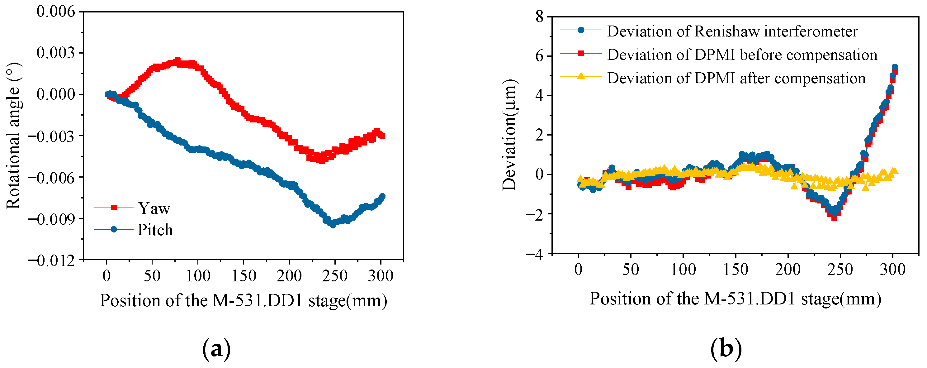
The experimental results of displacement comparison are shown in
Figure 6 and
Table 2. As shown in
Figure 6a, the maximum yaw and pitch angles of the M531.DD1 stage were −0.0048° and −0.0095°, respectively. As shown in
Figure 6b, the displacement measurement results of the Renishaw interferometer are shifted upward by 20 mm for clarity. The maximum deviation between the Renishaw interferometer and the stage positioning was 5.448 μm, with a standard deviation of 1.225 μm. Before rotational angle compensation, the maximum deviation between DPMI and the stage positioning was 5.207 μm, with a standard deviation of 1.214 μm. After rotational angle compensation, the maximum deviation between DPMI and the stage positioning was reduced to 0.719 μm, and the standard deviation was reduced to 0.263 μm. The experimental results showed that the proposed DPMI can effectively reduce the environmental disturbance in addition to reducing the rotation error in the displacement measurement and, therefore, can be applied for precise displacement measurement in the millimeter range.
4.4. Uncertainty Analysis
According to Equation (7), the uncertainty of yaw angle can be expressed as
where
u(λ) is the uncertainty of wavelength in the air;
u(d
1) is the uncertainty of distance in the x-direction between the first and second detectors in APD;
u(φ) is the uncertainty of phase demodulation accuracy. The maximum
−
is 59.86 mrad (3.43°), as the angle measurement range is from 0° to 0.01°. d
1 is 1750 μm, and the wavelength of the He-Ne laser is 0.632992 μm. As the uncertainty of the air refractive index is 3.0 × 10
−8, the standard air refractive index is 1.00027126, and the uncertainty of wavelength in air is 1.97 × 10
−5 nm. The uncertainty of d
1 is 1 μm, and the uncertainty of phase demodulation accuracy is 0.87 mrad (0.05°).
According to the above description, the uncertainties of the first, second, and third terms in Equation (9) are (3.07 × 10⁻¹²°)2, (5.64 × 10⁻⁸°)2, and (6.39 × 10⁻⁶°)2, respectively. Therefore, the total uncertainty of yaw angle u(θx) is 6.39 × 10⁻⁶°. Similarly, the uncertainty of pitch angle u(θy) is 5.85 × 10⁻⁶°. These uncertainty analyses are consistent with the experimental results.


