Article

Aerodynamics of a Train and Flat Closed-Box Bridge System with Train Model Mounted on the Upstream Track

1
School of Civil Engineering, Central South University, Changsha 410075, China
2
National Engineering Laboratory for High Speed Railway Construction, Changsha 410075, China
3
Joint International Research Laboratory of Key Technology for Rail Traffic Safety, Changsha 410075, China
*
Author to whom correspondence should be addressed.
Appl. Sci. 2022, 12(1), 276; https://doi.org/10.3390/app12010276
Submission received: 25 November 2021 / Revised: 23 December 2021 / Accepted: 25 December 2021 / Published: 28 December 2021
(This article belongs to the Special Issue New Advances in Fluid Structure Interaction)

Abstract

:
The aerodynamic features of a train and flat closed-box bridge system may be highly sensitive to train-bridge aero interactions. For the generally utilized railway bridge-deck with two tracks (the upstream and downstream ones), the aero interactions above are occupied-track-dependent. The present paper thus aims to reveal the aero interactions stated above via a series of wind tunnel tests. The results showed that the aero interactions of the present train-bridge system display four typical behaviors, namely, the underbody flow restraining effect, bridge deck shielding effect, flow transition promoting effect, and the flow separation intensifying effect. The above four aero interactions result in obvious reductions in the aerodynamic forces of the train in wind angle of attack α of [−4°, 12°] and in the static stall angle of the bridge-deck, and leads to sensible increases in the absolute values of the bridge aerodynamic forces in α of [−4°, 12°]. Upon comparing the results with the same train and bridge system but with the train model mounted on the downstream track, the quasi-Reynolds number effect was non-detectable when the train model was moved to the upstream track. Thus, no drag crisis and other saltatory aerodynamic behaviors were observed in the present study in α of [0°, 12°].

1. Introduction

Currently, railway vehicles need to run on or through long-span bridges, i.e., Hutong Yangtze river railway bridge, Jinshajiang railway bridge, and Strait of PingTan Bridge [1]. The serviceability of trains running on such long-span railway bridges is of major concern around the world [2,3,4]. In order to predict, control, and improve the serviceability of the train-bridge system in crosswinds, their aerodynamic properties and underlying flow physics should be fully investigated in advance.
From the train point of view, modern vehicles are more sensitive to crosswinds due to their higher operating speed and lighter weight [2,5]. To guarantee the operating comfortability and safety of a train running on scenarios of different types (flat ground, embankment, viaduct, and long-span bridge) in crosswinds, two kinds of risk analysis methods have been put forward, i.e., the mathematically rigorous approach developed by many previous researchers [4,6,7,8,9,10] and the characteristic wind curve (CSC) as documented in specification [11]. However, no matter which method is utilized, the wind loads acting on the train are the basic input parameters.
From the infrastructure scenario point of view, the long-span railway bridge is generally the most critical site in a segment [12]. Relative to other scenarios, the long-span railway bridge is characterized by smaller stiffness, lower damping, lighter weight, and severer wind environment. Moreover, the dynamic responses of the train and bridge system induced by crosswinds are chiefly resisted by the bridge. Given all the above characteristics, the crosswind aerodynamic properties of the railway bridge scenario should be taken into consideration in the risk analysis of the train and bridge system. Within the range of the CSC, the bridge deck may suffer from buffeting and vortex-induced vibration [13,14,15], which should have a strong negative effect on the serviceability of the train in crosswinds. To assess the dynamic responses of the long-span railway bridge induced by crosswinds, the aerodynamic properties of the bridge deck need to be measured, analyzed, and classified.
From the train-bridge system point of view, the aerodynamic and dynamic interactions between the train and bridge are very complex [16,17,18]. On one hand, the presence of the bridge deck should significantly impact the approaching and underbody flows of the train. For example, the leading-edge separated flow of the bridge-deck may lead to an overspeed effect on the approaching flow of the train, similar to Baker’s hypothesis [19]. Meanwhile, the flow separation-reattachment of the bridge-deck would be noticeably altered by the presence of the train. On the other hand, the dynamic responses of the train-bridge system are obviously intensified in crosswinds [4,6,7,8,9,10]. The above aerodynamic and dynamic interactions were mainly carried out on train-viaduct and train-truss bridge systems [4,18,20,21,22,23,24,25,26,27,28,29]. Associated studies on the train and flat closed-box bridge system are limited. Currently, the flat closed-box deck has been widely utilized in long-span railway bridges in China since 2014. For such a wind-sensitive bridge deck, systematic investigations on the aerodynamics of the train and flat closed-box bridge system are urgently required.
Generally, the relative spatial position of two objects (i.e., circular cylinders, square and rectangular prisms) plays a determining role in their aerodynamic forces, flow structures, pressure distributions, velocity fields, and near wakes [30,31,32]. When it comes to the train-infrastructure system, the change of the relative spatial position of the train and infrastructure is mainly influenced by the variations of the occupied track the train is running on. In the past decades, several studies have already been carried out to discuss the influences of the aforementioned occupied track variations on the aerodynamic properties of trains [12,22,26,33]. However, the influences of the occupied track variation on the crosswind aerodynamic characteristics and their underlying flow mechanisms of the train and bridge system are not yet fully understood. Thus, the present research carried out a series of wind tunnel tests to study the crosswind aerodynamic characteristics of a train and flat closed-box bridge system with the train model mounted on the upstream track, as well as the underlying flow physics. Compared to the case with the train model mounted on the downstream rack [34], the influences caused by the above occupied track variation are revealed.
Pressure field measurements and flow visualization results of a train and flat closed-box bridge are reported in the present study, which may be a meaningful complement to the aerodynamic interactions of the train-bridge system. The remainder of this paper is organized as follows. Section 2 depicts the detailed information of the wind tunnel test setups, including the wind tunnels, the testing models, the testing instruments, and the arrangements of the testing points. Section 3 and Section 4 discuss the aerodynamic interactions and properties of the train and flat closed-box bridge system, respectively. The results were then compared to the results of the same train-bridge system but with the train model mounted on the downstream track, and the influences caused by the occupied track variation were analyzed and classified. In Section 5, two core findings are summarized.

2. Configurations of Wind Tunnel Setup

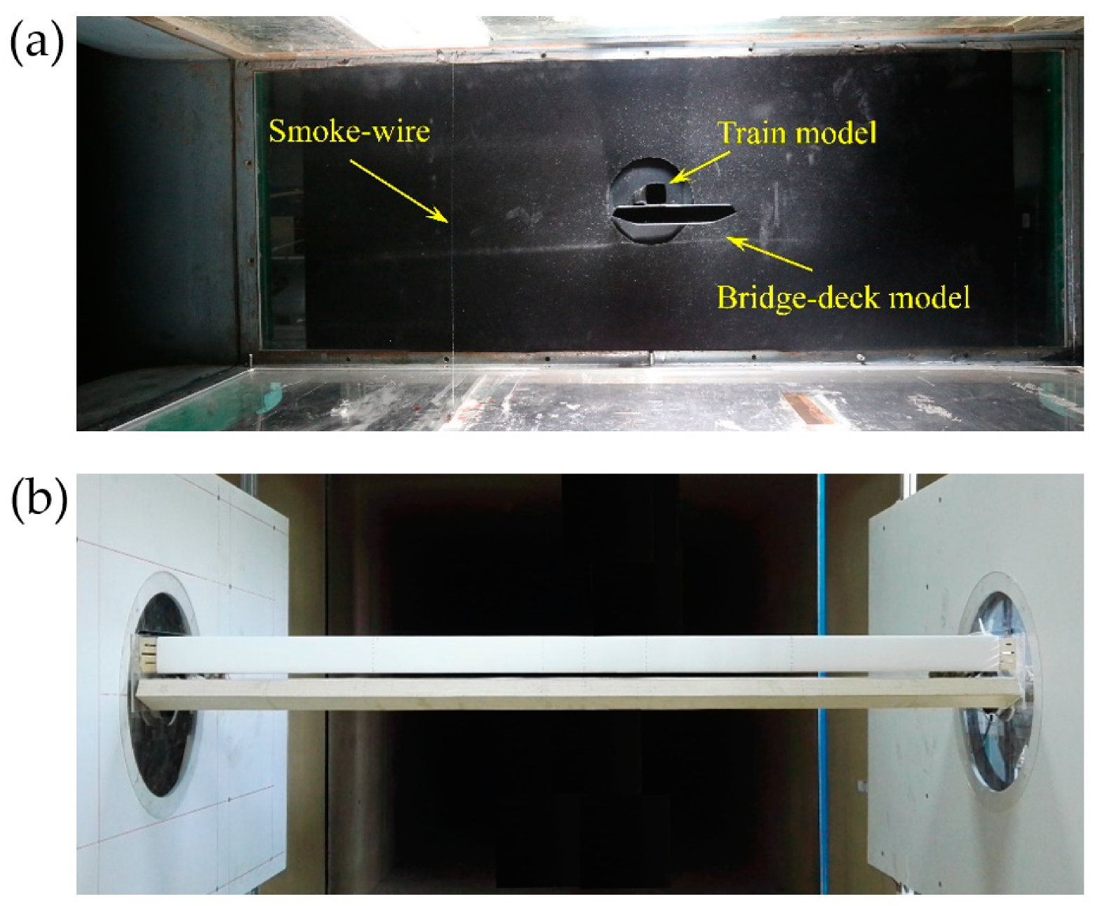
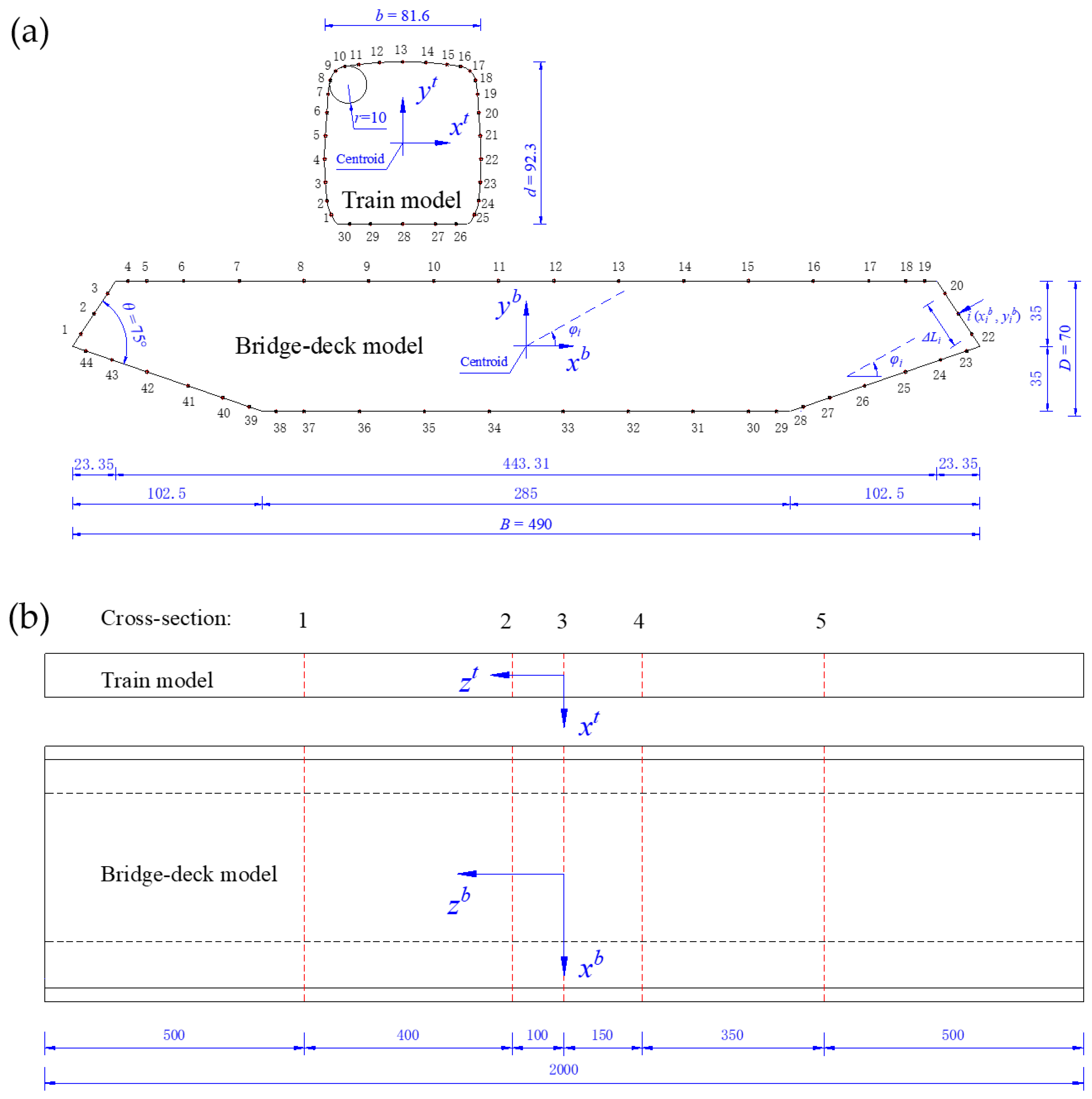
2.1. Wind Tunnels and Models

Two wind tunnels belonging to Central South University were utilized in these two experiment as shown in Figure 1a,b. The width and height of the test sections of these two wind tunnels are 450 mm × 450 mm and 3000 mm × 3000 mm, respectively. For clear representation, the smaller wind tunnel is named as WT-I, whereas the larger one is named as WT-II. Without any turbulence generators, the flow in the WT-I and WT-II with turbulence intensities smaller than 0.6% could be considered as uniform based on the current specification [11]. Please see [34] for more detailed geometric parameters of the above two wind tunnels.
Two groups of wind tunnel test models were made to match the WT-I and WT-II, which are simplified from a practical engineering model in China as shown in Figure 1. On one hand, as depicted in Figure 1a, the first group models scaled by 1:200 were used for smoke-wire visualization in WT-I. The widths, heights, and lengths of the train and bridge-deck models are b × d × l = 16.3 mm × 18.5 mm × 450.0 mm and B × D × L = 98.0 mm × 14.0 mm × 450.0 mm, respectively, resulting in a maximum blockage ratio of 6.2%. In this flow visualization experiment, the models were made by 3D printing technique. The wind angle of attack α was set in [−12°, 12°] with an interval of 2°. The incoming flow velocity is U = 2 m/s, and the corresponding Reynolds number (Re) based on U and d is of 2.5 × 10³. On the other hand, the second group of models scaled by 1:40 were used for pressure field and flow profile measurements as shown in Figure 1b in WT-II. The widths, heights, and lengths of the train and bridge-deck models are b × d × l = 81.6 mm × 92.3 mm × 2000.0 mm and B × D × L = 490.0 mm × 70.0 mm × 2000.0 mm, respectively, resulting in a maximum blockage ratio of 4.6%. For brevity, only the geometrics of this group of models are depicted in Figure 2. In the pressure field and profile measurement experiment, the train model was still made by 3D printing technique, whereas the bridge-deck model was made of wood with an aluminum spine embedded inside. The test range of α was also set in [−12°, 12°] with an interval of 2°, while the incoming flow velocity is U = 20 m/s corresponding to Re = 1.25 × 10⁵ (based on U and d). Please note that, only the train’s shoulders are rounded without any sharp corners, thus all the Reynolds numbers in this paper are calculated based on d.
As described in Figure 2, xtyt and xbyb denote the geometric coordinate systems of the train and bridge-deck models, respectively. The coordinate origins are fixed at the centroids of the cross sections of the test models.

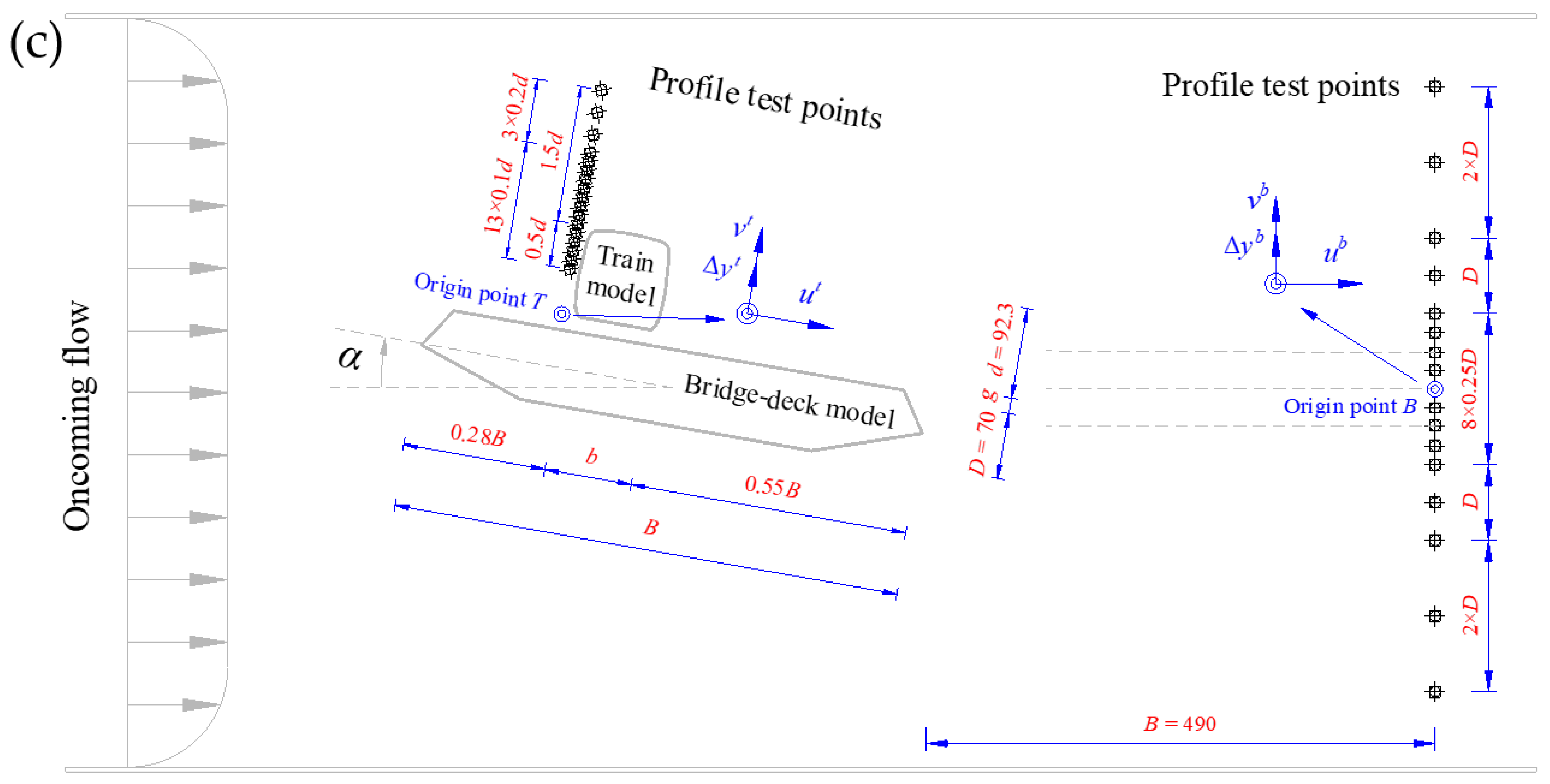
2.2. Testing Points and Instruments

The pressure fields around the test models were measured by pressure taps pre-installed on their surfaces as shown in Figure 2a,b. In the streamwise direction, there are 30 and 44 taps distributed around the train and bridge-deck models, respectively. In the spanwise direction, there are five pressure test cross-sections. In total, six scanner (Scanivalve, ZOC33/64PxX2) modes were used to record the pressure signals of all the above 370 pressure taps. The sampling frequency and duration of all six scanner modes were modulated as 625 Hz and 32 s, respectively. Note that, the Strouhal number of the present model is smaller than 0.18 corresponding to a vortex shedding mode less than 40 Hz, thus the time delay 1/625 s between any two taps caused by the scanner is neglected. The pressure tap and scanner were connected by PVC tubing system with a length of 500 mm. As demonstrated by [17], the influence caused by this PVC tubing system is less than 8%, which is also neglected in this research.
A Cobra probe was utilized to monitor the flow profiles of the present models, which was mounted on a 3D traverse system with a displacement resolution of 0.02 mm as demonstrated in Figure 2c. The sampling frequency and duration of the Cobra probe were modulated as 2000 Hz and 30 s, respectively.
As depicted in Figure 2c, the flow profile coordinate system is defined as u (the streamlined component) and v (the vertical component). For the train approaching flow, the coordinate origin A is fixed at the bottom of the train model. For the bridge-deck near wake, the coordinate origin B is fixed on the nose-tail line of the bridge-deck. Δytyb are the vertical coordinates of the test points.

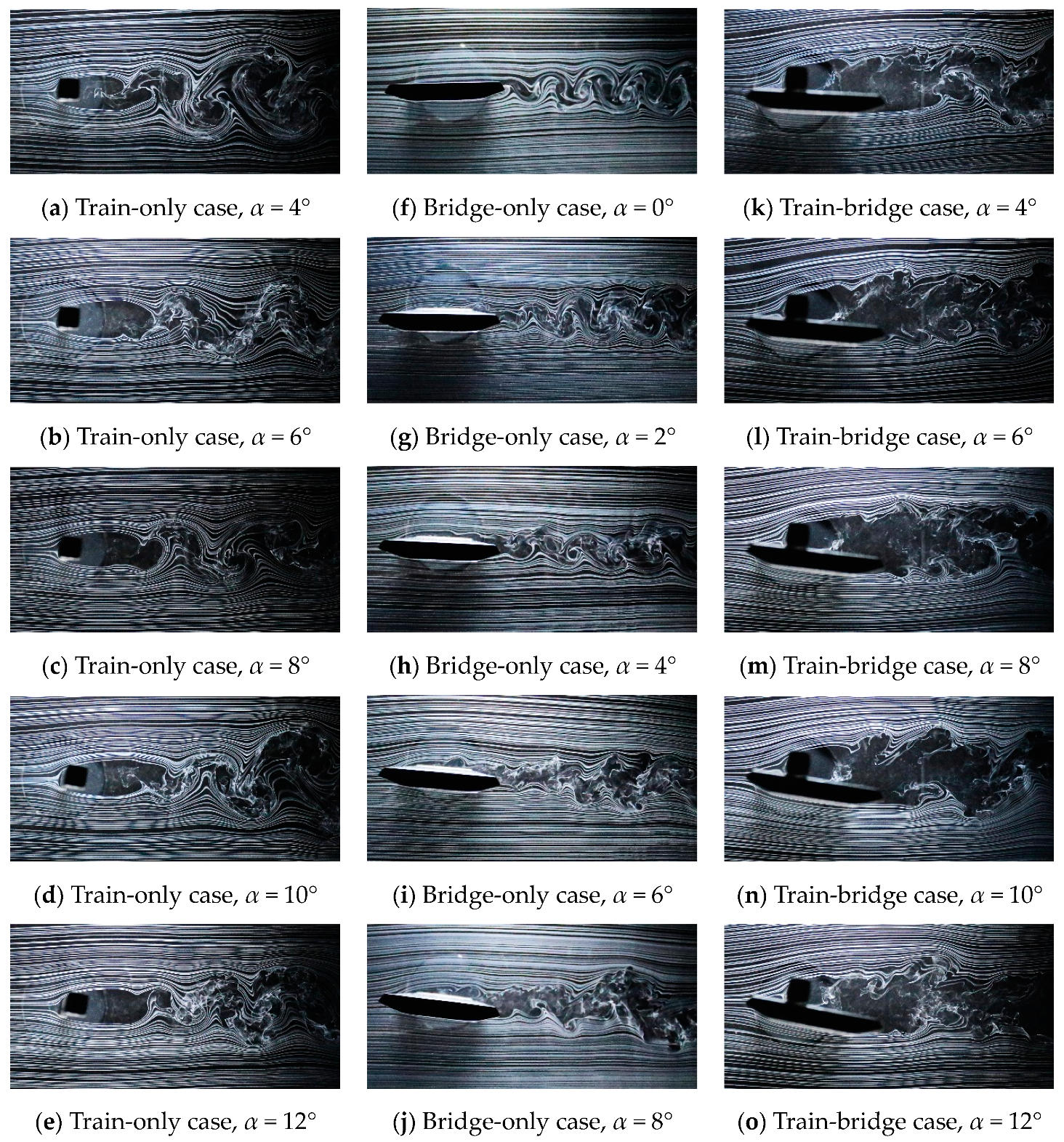
3. Aerodynamic Interactions

This section depicts the instantaneous flow structures around the present models, the approaching flow profiles of the train model, and the pressure fields and near wake profiles of the bridge-deck model. Based on the above experimental results, the train-bridge aero interactions in crosswinds were analyzed and compared to the study of [34] in order to reveal the effects of the occupied track variation (with train model mounted on the upstream or downstream track) on the aero interactions of the train and bridge system.

3.1. Train Model

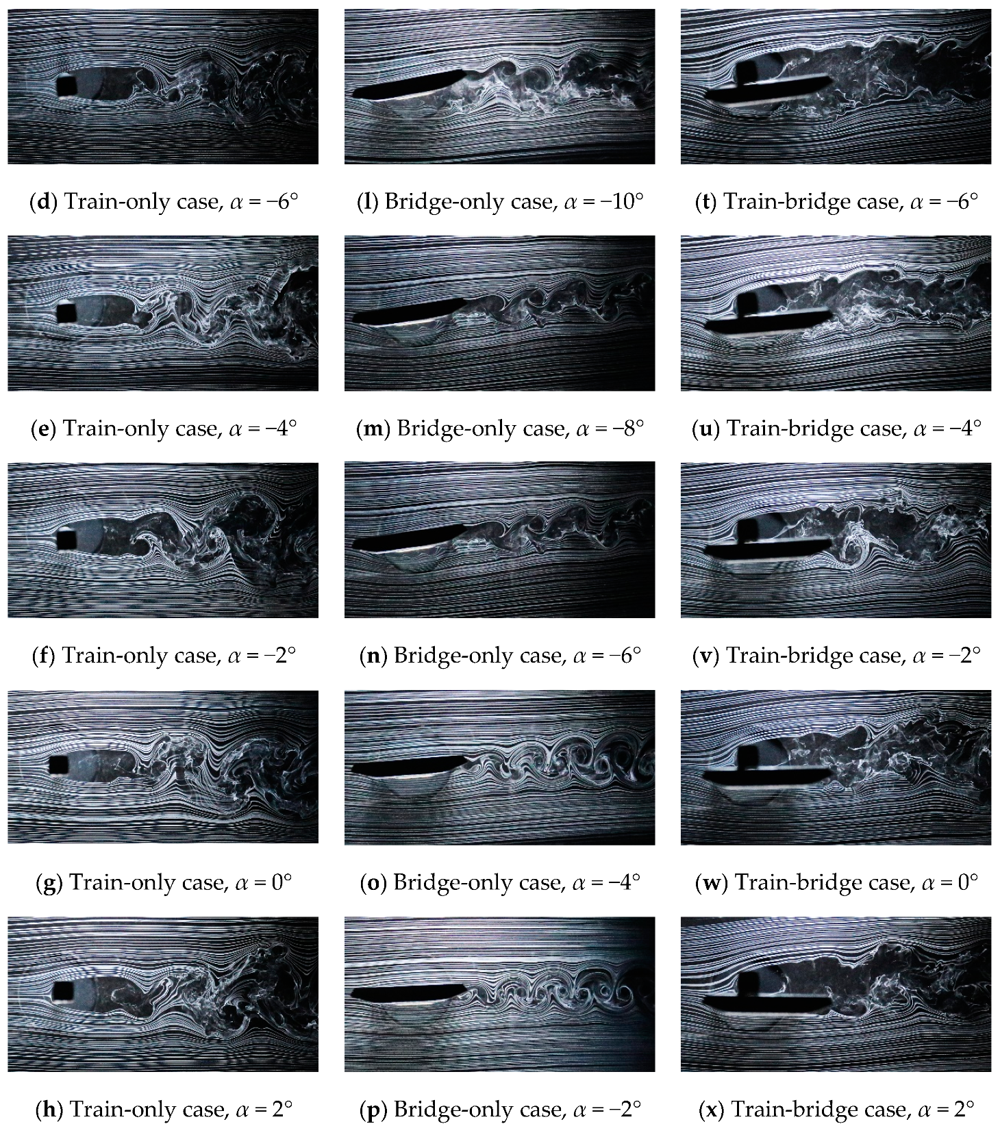
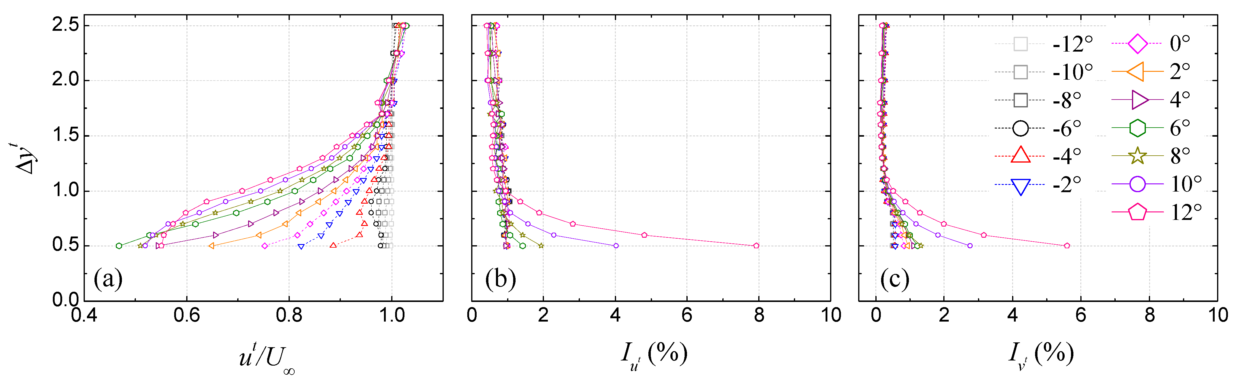
3.1.1. Underbody Flow Restraining Effect

Figure 3 and Figure 4 depict the instantaneous flow structures around the test models in the train-only, bridge-only, and train-bridge (with the train model mounted on the upstream track) cases. As shown in the left columns of Figure 3 and Figure 4, the underbody flow of the train-only model generally transits from full separation to intermittent reattachment with an increase in α in [−12°, 12°]. Interacting with the roof separated flow, a typical Karman vortex street appears in the near wake of the train model similar to that of a circular cylinder. However, as demonstrated in the right columns of Figure 3 and Figure 4, the underbody flow separation of the train model is noticeably decaying with the appearance of the bridge-deck model, as was evidenced by only a small piece of smoke-wire going through the gap between the train and bridge models. Even through the roof flow separation, reattachment is still detectable; no Karman vortex street can be observed in the near wake of the train model. Obviously, the chief reason for the above weakened underbody flow separation is the presence of the bridge deck model. Based on the above-mentioned discussion, the bridge deck has a strong restraining effect on the underbody flow separation of the train model.
In comparison with the study of [34], the underbody flow separation of the train model in the present study is still detectable, as evidenced by a small piece of smoke-wire, suggesting the underbody flow restraining effect is a smoother dependence in the occupied track variation.

3.1.2. Bridge Deck Shielding Effect

In the bridge-only case, the shear layer thickness of the leading-edge separated flow over the bridge-deck upper surface is limited in α = [−16°, 2°] as evidenced by the middle columns of Figure 3i–o and Figure 4f,g. With an increase in α = [4°, 8°], the above shear layer thickness increases noticeably as shown in Figure 4h–j. In the train-bridge case, the above leading-edge separated flow reattaches on the upstream surface of the train model, and then bifurcates into two parts, as shown in the right columns of Figure 3 and Figure 4. With an increase in α = [−12°, 12°], the stagnation point (bifurcation) of the leading-edge shear layer is always located at the 1/4 height of the train model, which is larger than the train-bridge gap, suggesting that this leading-edge shear layer may have a shielding effect on the train model.
To quantitatively identify the above-mentioned bridge deck shielding effect, the approaching flow profiles of the train model were monitored by a Cobra probe as shown in Figure 5. Due to the ±45° conical measurement area of the Cobra probe, the flow profiles in the range of 0 ≤ Δyt ≤ 0.5 could not be effectively tested and thus are not shown here. In Figure 5a, the streamlined component of the normalized mean velocity u/U is always smaller than 1.0 in Δyt = [0.5, 1.5], evidencing the above achieved shielding effect in all the test ranges of α = [−12°, 12°]. However, in the range of α = [−12°, −6°], this bridge-deck shielding effect was limited, as is evidenced by the u/U ≈ 1.0 flow profile. With an increase in α = [−4°, 12°], this bridge deck shielding effect is remarkably enhanced as is evidenced by the noticeably decaying u/U profile and obviously intensifying turbulence intensities Iu & Iv profiles in Δyt = [0.5, 1.0], respectively.
When compared to the study of [34], two striking differences can be summarized here. Firstly, no speed-up shear layer can be detected in the approaching flow of the train model mounted on the upstream track, which leads to the disappearance of the quasi-Reynolds number effect [34]. Then, the space upstream from the train is compressed when the train model is mounted on the upstream track, which leads to limited room for the development of the leading-edge shear layer of the bridge-deck model. Thus, the stagnation point of the train approaching flow is almost α-independent. Otherwise, the location of this stagnation point shall be a function of α as discussed in [34].

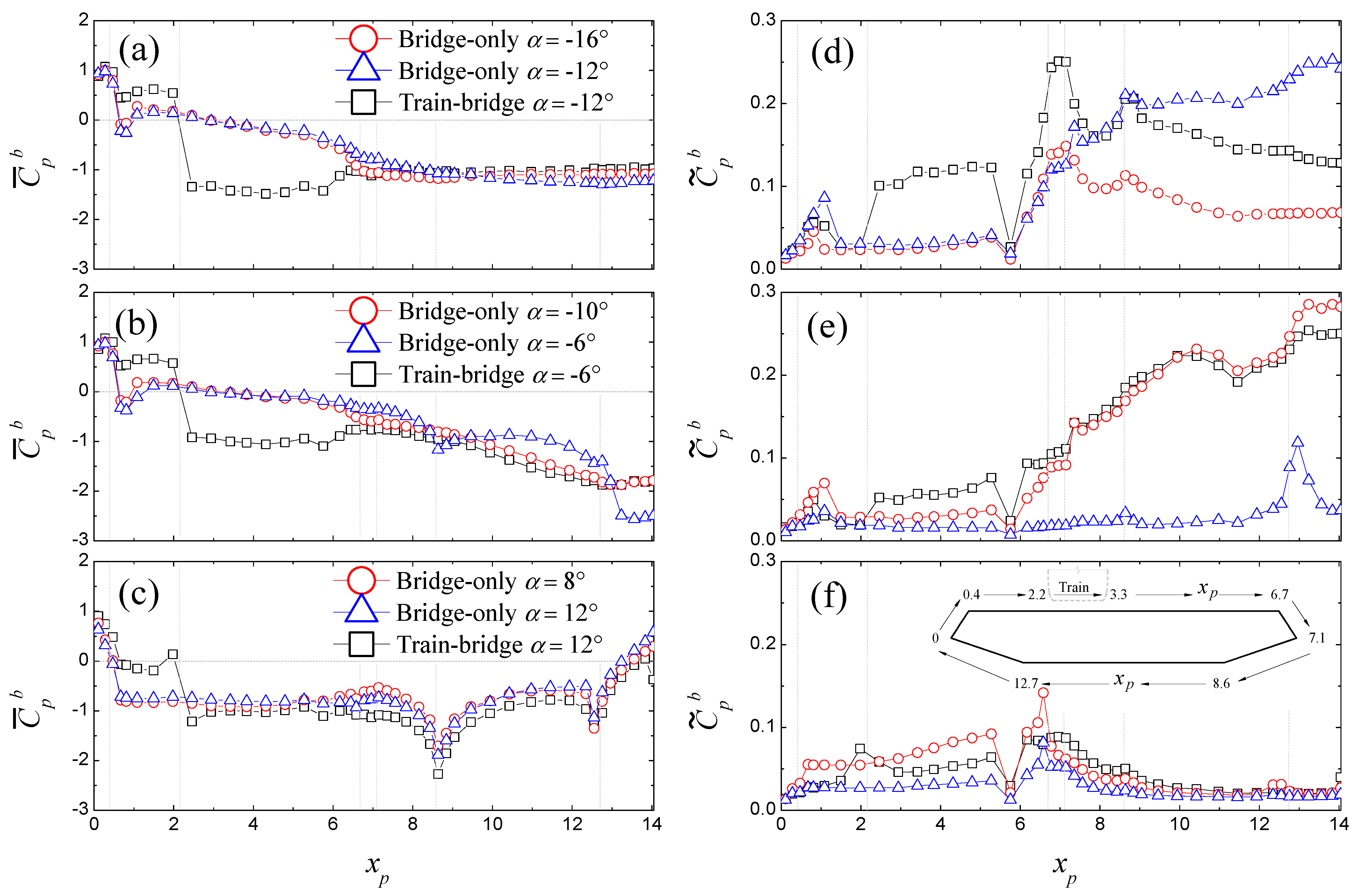
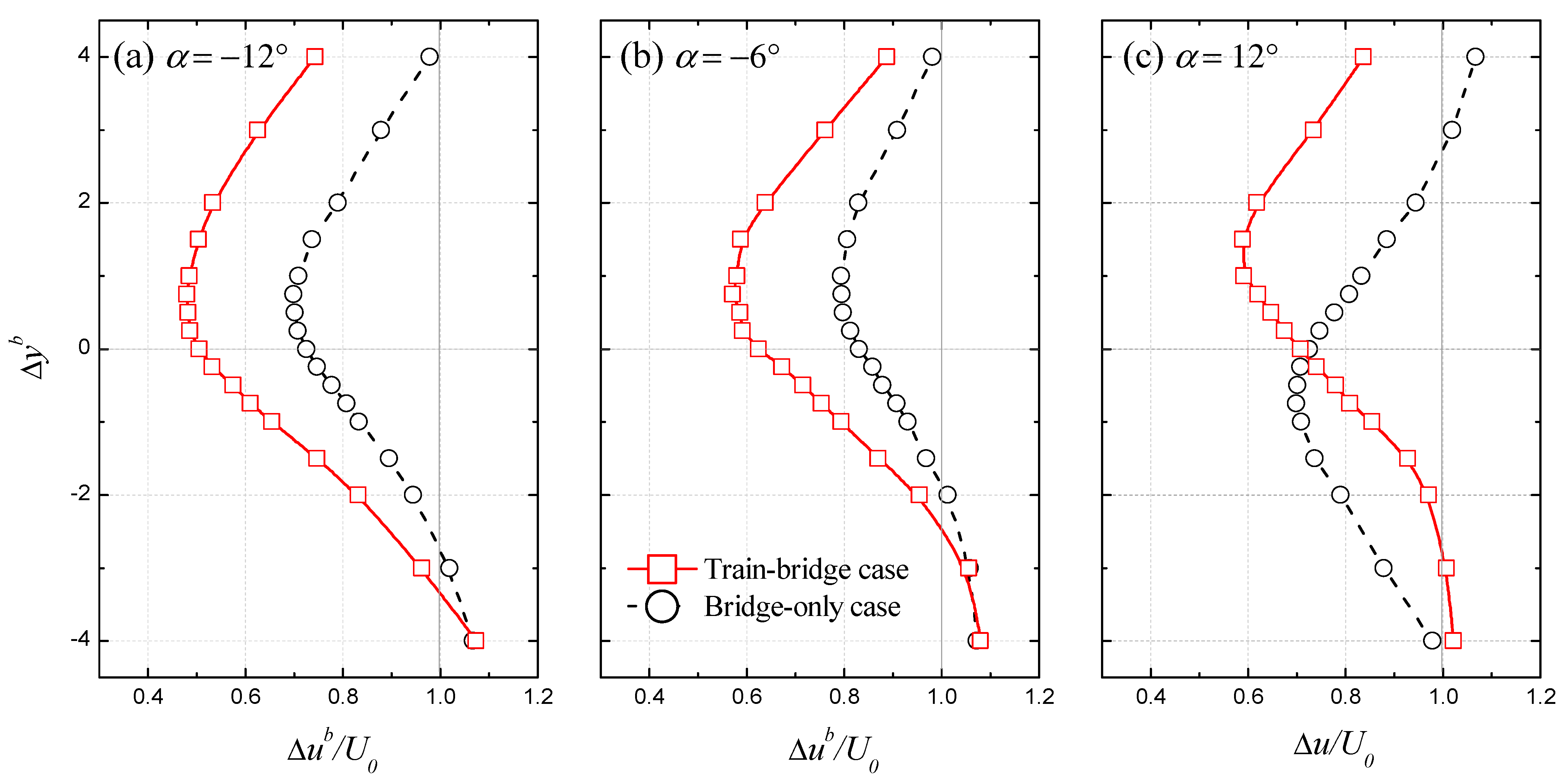
3.2. Bridge-Deck Model

3.2.1. Flow Transition Promoting Effect

In Figure 3 and Figure 4, the instantaneous flow structures of the bridge-only model in α = [−16°, 12°] are depicted in the middle columns. Based on previous studies [31,35,36], the lower half bridge-deck is characterized by leading-edge vortex shedding (LEVS) in α = [−16°, −12°], impinging leading-edge vortices (ILEV) in α = [−10°, −8°], and trailing-edge vortex shedding (TEVS) in α = [−6°, 12°]. However, the corresponding α ranges of the above three typical flow patterns (i.e., LEVS, ILEV, and TEVS) in the train-bridge case are α = [−12°, −8°], α = [−6°, −4°], and α = [−2°, 12°] as shown in the right columns of Figure 3 and Figure 4, respectively. In other words, the critical |α| of the above three typical flow patterns transiting from one to another on the lower half bridge-deck is reduced by about 4° with the presence of the train model. Moreover, Figure 6 can quantitively re-confirm the above flow transition promoting phenomenon. By comparison, the pressure distribution in xp = 7.3~14.1 at αi in the train-bridge case is in line with that at αi − 4° in the bridge-only case. That is to say, the critical |α| of the flow transition of the lower half bridge-deck model is reduced by about 4° with the presence of the train model.
Upon comparison with the study of [34], the flow behaviors around the lower half bridge-deck model are almost the same as when the train model is mounted on the upstream and downstream tracks, suggesting the flow transition promoting effect is insensitive to the occupied track variation.

3.2.2. Flow Separation Intensifying Effect

As shown in the middle columns of Figure 3 and Figure 4, the dominated flow patterns of the upper half bridge-deck model in the bridge-only case are still LEVS, ILEV, and TEVS, similar to those of the lower half bridge-deck. However, with the presence of the train model, the upper half bridge-deck model is always controlled by flow separation from the upper half of the train model, as described in the right columns of Figure 3 and Figure 4. Generally, the flow separated from the train roof overshoots the entire upper half bridge-deck model resulting in a wider near wake than that of the corresponding bridge-only case, which can also be evidenced by a selected comparison of the wake profiles of the bridge-deck model as shown in Figure 7.
The above comparisons of the instantaneous flow structures and near wake profiles between the train-bridge and bridge-only cases suggest that the intensity of the flow separated from the train model is much stronger than that of the bridge-deck model, namely, the flow separation intensifying effect.
Compared to the study of [34], the space downstream from the train model is expanded, which results in enough room for the development of the roof separated flow of the train model. Thus, the flow separation intensifying effect of the present study is much stronger as is evidenced by the wider and deeper near wake.

4. Aerodynamic Characteristics

This section presents the aerodynamic force coefficients of the present models. Compared to several previous studies, the present experiment is verified. The aerodynamic properties of the downstream case reported by [34] are also illustrated here to reveal the influences of the occupied track variation on the aerodynamic features of the train-bridge system.

4.1. Aerodynamic Force Coefficients
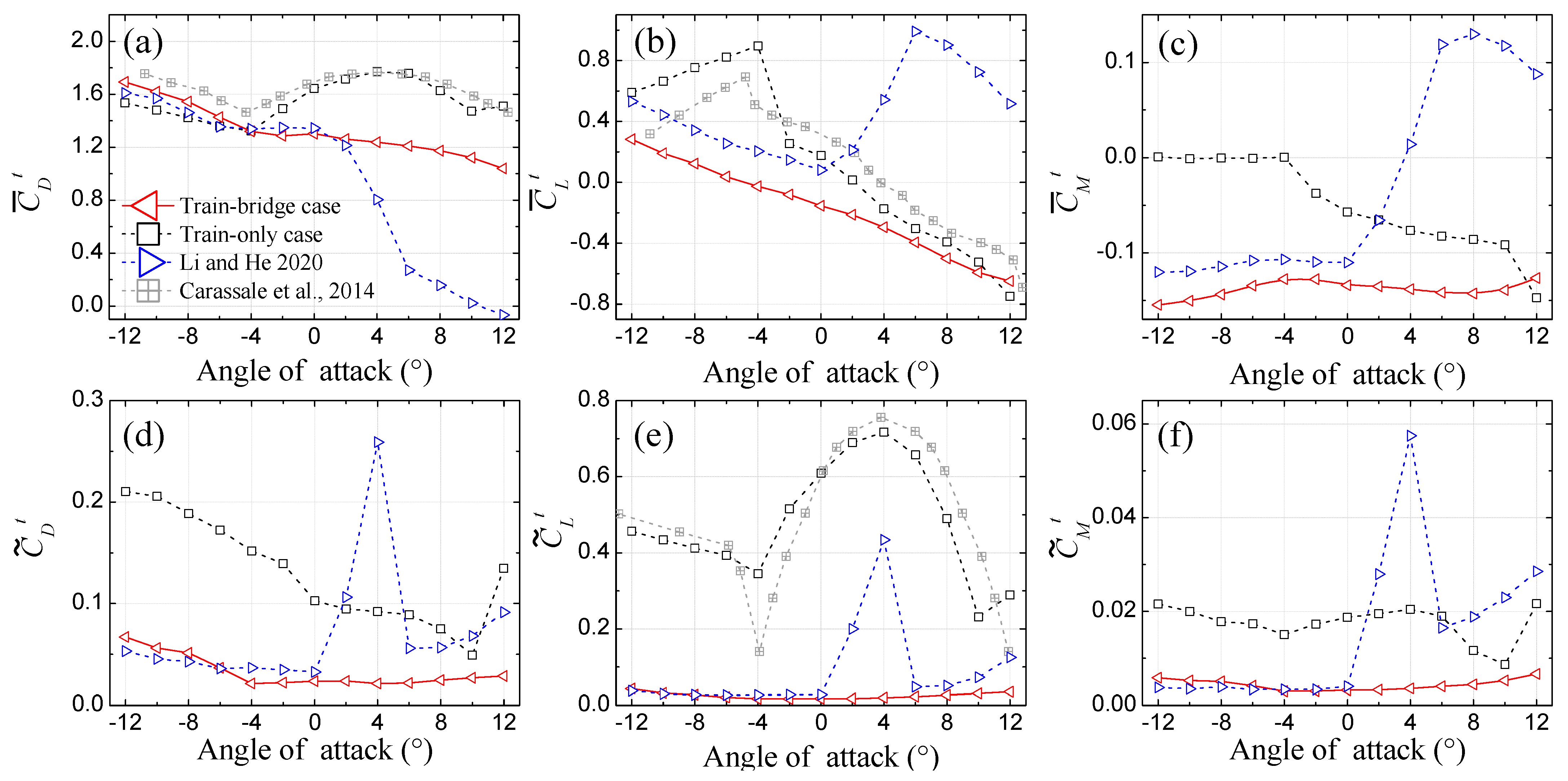
The aerodynamic force coefficients are calculated via the pressure field test results. C ¯ D t , C ¯ L t , C ¯ M t , C ˜ D t , C ˜ L t , and C ˜ M t are the mean and fluctuating drag, lift, and moment coefficients of the train model, whereas C ¯ D b , C ¯ L b , C ¯ M b , C ˜ D b , C ˜ L b , and C ˜ M b are the mean and fluctuating drag, lift, and moment coefficients of the bridge-deck model, respectively. The detailed definitions about the above force coefficients are available in [34].
Figure 8 and Figure 9 present the aerodynamic force coefficients of the train and bridge-deck models, respectively. For verification, the experimental results of the train-only case, bridge-only case, [37,38,39] are also illustrated here. As demonstrated in Figure 8a,b,e and Figure 9b,c, the results of the train-only and bridge-only cases show good agreements with those from previous studies when taking into consideration differences of the experimental models. Because all the present cases were carried out under similar conditions, the above comparisons verify the present investigation.
As shown in Figure 8a, C ¯ D t in the train-only and train-bridge cases is in good consistency with each other in α = [−12°, −6°], while C ¯ D t in the train-bridge case is much smaller than that in the train-only case in α = [−4°, 12°], suggesting a strong bridge-deck shielding effect. The above two typical behaviors of C ¯ D t in different ranges of α are in fair agreement with the flow visualization and flow profile test results as shown in Section 3.1.2. As demonstrated in Figure 8d–f, C ˜ D t , C ˜ L t , and C ˜ M t in the train-bridge case are much smaller than those in the train-only case, which shall be attributed to the underbody flow restraining effect as concluded in Section 3.1.1.
In comparison with the study of [34] the effects caused by the occupied track variation on the aerodynamic force coefficients of the train model can be concluded by the following two aspects as shown in Figure 8:
(a)
In α = [0°, 12°], no abrupt changes, i.e., drag crisis (Figure 8a), jumping and recovering of lift, moment, and three fluctuating force coefficients (Figure 8b–f), can be observed in the present study. As concluded in Section 3, these differences shall be chiefly caused by the disappearance of the quasi-Reynolds number effect.
(a)
In α = [−12°, 0°], the C ¯ D t , C ¯ L t , and C ¯ M t in the two cases with train model mounted on the upstream and downstream tracks share almost the similar behaviors, as described in Figure 8a–c. However, the C ¯ L t in the present study is reduced by 0.23 in the range of α = [−12°, 0°].
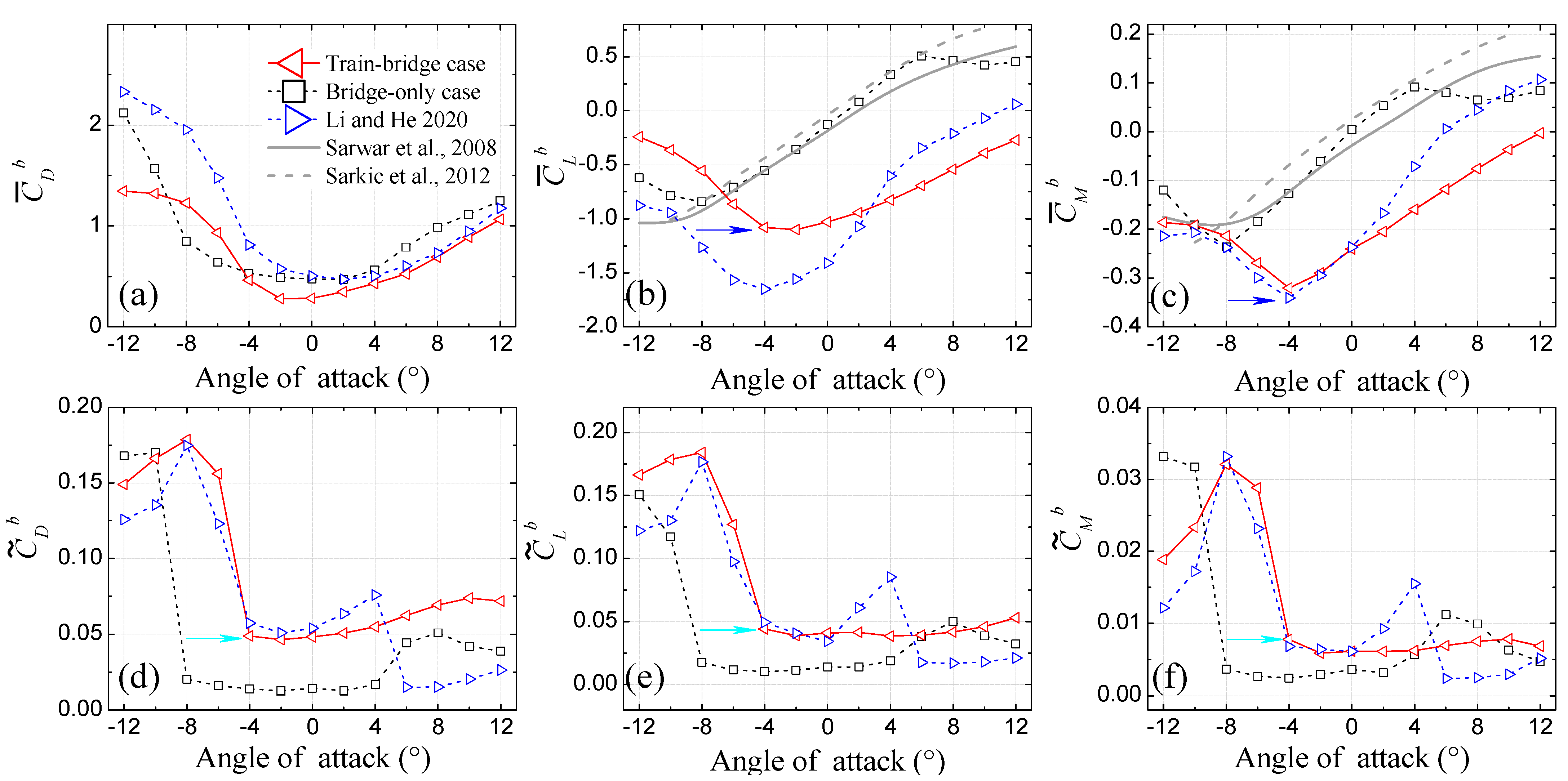
As demonstrated in Figure 9b–f, the stall angle of the bridge-deck model in the train-bridge case is about α = −4°, which is about 4° larger than that of the bridge-only case as highlighted by two blue arrows in Figure 9b,c. The variation of the stall angle shall be attributed to the flow transition promoting effect as summarized in Section 3.2.1. Moreover, the C ˜ D b , C ˜ L b , and C ˜ M b are enhanced with the appearance of the train model as shown in Figure 9d–f, which shall be ascribed to the flow separation intensifying effect as concluded in Section 3.2.2.
Similarly, the effects caused by the occupied track variation on the aerodynamic force coefficients of the bridge-deck model can also be summarized into two aspects as follows:
(a)
In α = [0°, 12°], no abrupt changes, i.e., jumping and recovering of C ¯ L b , C ¯ M b , C ˜ D b , C ˜ L b , and C ˜ M b can be observed in the present study relative to those of [34]. Obviously, this difference shall also be caused by the disappearance of the quasi-Reynolds number effect as concluded in Section 3.1.2.
(b)
In α = [−12°, 0°], C ¯ M b , C ˜ D b , C ˜ L b , and C ˜ M b in the two cases with train model mounted on the upstream and downstream tracks display similar behaviors, while the values of | C ¯ D b | and | C ¯ L b | in the present study are much smaller than those of [34].

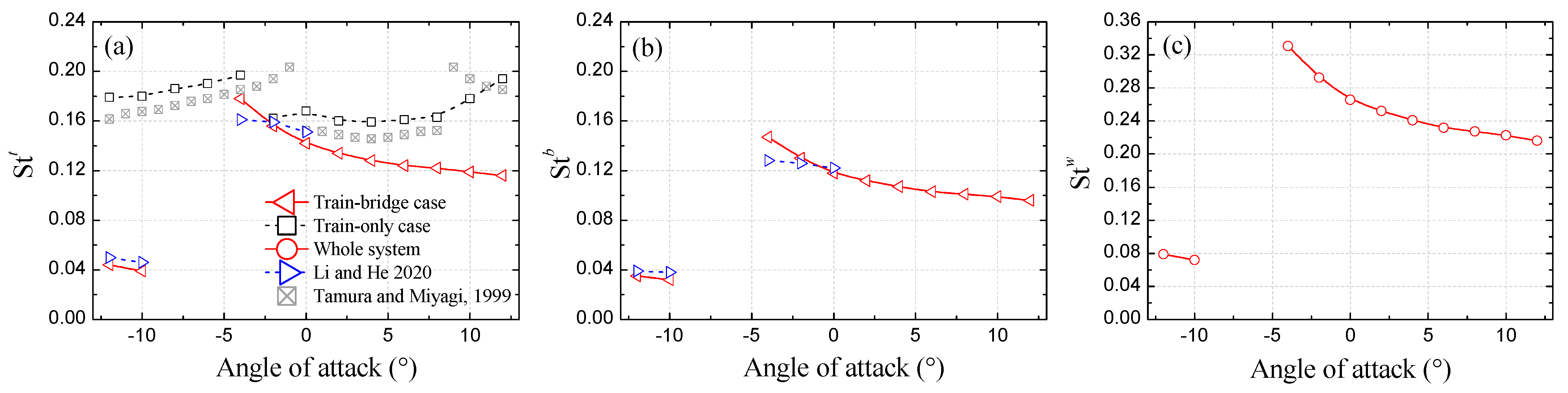
4.2. Strouhal Numbers

The Strouhal numbers (Stt, Stb, and Stw for the train, bridge-deck, and whole train-bridge models, respectively) are calculated via the power spectral densities (PSDs) of the model lifts based on d, D, and d + D, respectively.
Figure 10a,b depicts the Stt and Stb in the range of α = [−12°, 12°]. The results of an infinite prism tested by [40] and the train model in the train-only case are also demonstrated here for comparison. Generally, the train-only results highly mimic those of [40], again suggesting a validation of the present investigation.
The Strouhal numbers of the present models in the train-bridge case displays similar behavior but with different values as described in Figure 10a,b, respectively. That is expected because the train, bridge deck, and the whole train-bridge share a similar vortex shedding frequency.
As shown in Figure 10, the behaviors of the Strouhal numbers in the train-bridge case in all the test ranges of α = [−12°, 12°] can be classified into three aspects. In α = [−12°, −10°], the Strouhal numbers of the present models are about 0.04. In α = [−8°, −6°], no Strouhal numbers can be identified both on the train and bridge-deck models. If a rectangular bluff body is governed by the impinging leading-edge vortices flow pattern (as mentioned in Section 3.2.1) at large Reynolds number, the periodic vortex shedding from the model is almost imperceptible [31,41]. For the present train-bridge system, the lower half bridge-deck is governed by the ILEV flow pattern in this range of α as summarized in Section 3.2.1, and the inflow Reynolds number based on d is 1.25 × 10⁵ belonging to the large Reynolds number [41]. Thus, the underlying mechanism of this Strouhal number disappearance shall be this ILEV flow pattern. In α = [−4°, 12°], both the Strouhal numbers of the train and bridge-deck models decreases gradually.
Upon comparing with the study of [34] with the train model mounted on the downstream track, the present study with the train model mounted on the upstream track can still identify the Strouhal numbers in α = [0°, 12°]. As pointed out by [42], the periodic vortex shedding of a circular cylinder tends to cease with an increase in Reynolds number in critical, transcritical, and supercritical regimes. As discussed in [34], the quasi-Reynolds number effect highly mimics the classical Reynolds number effect. Moreover, the above quasi-Reynolds number effect governs the main flow features of the train-bridge system with the train model mounted on the downstream track in α = [0°, 12°]. Thus, due to the disappearance of the quasi-Reynolds number effect in the present study, the detectable Strouhal numbers in α = [0°, 12°] here are reasonable.

5. Concluding Remarks

The aerodynamic features of a train and flat closed-box bridge system with a train model mounted on the upstream track was investigated via wind tunnel tests. Compared to the train-only and bridge-only cases, the aero interactions of the train and bridge system were examined. Compared to the same train and bridge system but with the train model mounted on the downstream track, the effects of the occupied track (with the train model mounted on) variation of the train model on the aerodynamic properties of the train and bridge system are revealed. Core findings are summarized as follows.
(1) The aero interactions of the train and flat closed-box bridge system can be roughly categorized as the underbody flow restraining effect (UFR), bridge deck shielding effect (BDS), quasi-Reynolds number effect (Q-Rey), flow transition promoting effect (FTP), and flow separation intensifying effect (FSI). Among these, the FTP was insensitive to the occupied track variation of the train model, whereas the UFR, BDS, FSI, and Q-Rey were dependent on the occupied track variation, especially for Q-Rey, which disappeared when the train model was mounted on the upstream track. The Q-Rey disappearance was mainly attributed to the speed-up leading-edge shear layer of the bridge-deck not reattaching on the rounded shoulder of the train model mounted on the upstream track.
(2) The aerodynamic features of the train and flat closed-box bridge deck models are very sensitive to aero interactions and occupied track variations. The aero interaction resulted in obvious reductions in the aerodynamic forces of the train at the wind angle of attack α of [−4°, 12°] and in the static stall angle of the bridge, and led to sensible increases in the absolute values of the aerodynamic forces of the bridge in α of [−4°, 12°]. The occupied track variation caused the disappearance of the drag crisis and other saltatory aerodynamic behaviors of the train-bridge system in α = [0°, 12°].

Author Contributions

Conceptualization, X.H.; methodology, H.L.; experiments, H.W. and H.L.; software, H.W.; validation, H.L. and X.H.; writing, H.W. and H.L.; supervision, X.H.; funding acquisition, X.H. and H.L. All authors have read and agreed to the published version of the manuscript.

Funding

This research was funded by Natural Science Foundation of Hunan province under Grant No. 2021JJ40744, and by National Natural Science Foundations of China under Grant No. 51925808 and U1934209.

Institutional Review Board Statement

Not applicable.

Informed Consent Statement

Not applicable.

Data Availability Statement

Data are contained within this article.

Acknowledgments

The authors thank the reviewers for their great help on the article during its review progress.

Conflicts of Interest

The author(s) declared no potential conflict of interest with respect to the research, authorship, and/or publication of this article.

References

  1. He, X.; Wu, T.; Zou, Y.; Chen, Y.F.; Guo, H.; Yu, Z. Recent developments of high-speed railway bridges in China. Struct. Infrastruct. Eng. 2017, 13, 1584–1595. [Google Scholar] [CrossRef]
  2. Baker, C. The flow around high speed trains. J. Wind Eng. Ind. Aerodyn. 2010, 98, 277–298. [Google Scholar] [CrossRef]
  3. Baker, C.; Johnson, T.; Flynn, D.; Hemida, H.; Quinn, A.; Soper, D.; Sterling, M. Train Aerodynamics: Fundamentals and Applications; Butterworth-Heinemann: Cambridge, MA, USA, 2019. [Google Scholar]
  4. Li, Y.; Qiang, S.; Liao, H.; Xu, Y.L. Dynamics of wind–rail vehicle–bridge systems. J. Wind Eng. Ind. Aerodyn. 2005, 93, 483–507. [Google Scholar] [CrossRef]
  5. Baker, C. A review of train aerodynamics Part 1–Fundamentals. Aeronaut. J. 2014, 118, 201–228. [Google Scholar] [CrossRef]
  6. Olmos, J.M.; Astiz, M.A. Improvement of the lateral dynamic response of a high pier viaduct under turbulent wind during the high-speed train travel. Eng. Struct. 2018, 165, 368–385. [Google Scholar] [CrossRef]
  7. Olmos, J.M.; Astiz, M.A. Non-linear vehicle-bridge-wind interaction model for running safety assessment of high-speed trains over a high-pier viaduct. J. Sound Vib. 2018, 419, 63–89. [Google Scholar] [CrossRef]
  8. Xia, H.; Zhang, N.; Guo, W.W. Analysis of resonance mechanism and conditions of train-bridge system. J. Sound Vib. 2006, 297, 810–822. [Google Scholar] [CrossRef]
  9. Xu, Y.L.; Ding, Q.S. Interaction of railway vehicles with track in cross-winds. JFS 2006, 22, 295–314. [Google Scholar] [CrossRef]
  10. Xu, Y.L.; Zhang, N.; Xia, H. Vibration of coupled train and cable-stayed bridge systems in cross winds. Eng. Struct. 2004, 26, 1389–1406. [Google Scholar] [CrossRef]
  11. CEN. Railway Applications-Aerodynamics-Part 6: Requirements and Test Procedures for Cross Wind Assessment. 2010, 14067-6. Available online: https://standards.iteh.ai/catalog/standards/cen/a9acedac-3968-4b8c-a6cc-5a035c91e9b3/en-14067-6-2018 (accessed on 24 December 2021).
  12. Cheli, F.; Ripamonti, F.; Rocchi, D.; Tomasini, G. Aerodynamic behaviour investigation of the new EMUV250 train to cross wind. J. Wind Eng. Ind. Aerodyn. 2010, 98, 189–201. [Google Scholar] [CrossRef]
  13. Gao, D.; Chen, W.; Eloy, C.; Li, H. Multi-mode responses, rivulet dynamics, flow structures and mechanism of rain-wind induced vibrations of a flexible cable. J. Fluids Struct. 2018, 82, 154–172. [Google Scholar] [CrossRef]
  14. Gao, D.; Chen, W.-L.; Zhang, R.-T.; Huang, Y.-W.; Li, H. Multi-modal vortex- and rain–wind-induced vibrations of an inclined flexible cable. Mech. Syst. Signal Processing 2019, 118, 245–258. [Google Scholar] [CrossRef]
  15. Gao, D.; Deng, Z.; Yang, W.; Chen, W. Review of the excitation mechanism and aerodynamic flow control of vortex-induced vibration of the main girder for long-span bridges: A vortex-dynamics approach. J. Fluids Struct. 2021, 105, 103348. [Google Scholar] [CrossRef]
  16. He, X.H.; Li, H. Review of aerodynamics of high-speed train-bridge system in crosswinds. J. Cent. South Univ. 2020, 27, 1054–1073. [Google Scholar] [CrossRef]
  17. Li, H.; He, X.H.; Wang, H.F.; Kareem, A. Aerodynamics of a scale model of a high-speed train on a streamlined deck in cross winds. J. Fluids Struct. 2019, 91, 102717. [Google Scholar] [CrossRef]
  18. Li, X.-Z.; Wang, M.; Xiao, J.; Zou, Q.-Y.; Liu, D.-J. Experimental study on aerodynamic characteristics of high-speed train on a truss bridge: A moving model test. J. Wind Eng. Ind. Aerodyn. 2018, 179, 26–38. [Google Scholar] [CrossRef]
  19. Baker, C. The determination of topographical exposure factors for railway embankments. J. Wind Eng. Ind. Aerodyn. 1985, 21, 89–99. [Google Scholar] [CrossRef]
  20. Barcala, M.A.; Meseguer, J. Visualization study of the influence of parapets on the flow around a train vehicle under cross winds. WIT Trans. Built Environ. 2008, 103, 797–806. [Google Scholar] [CrossRef] [Green Version]
  21. Barcala, M.A.; Meseguer, J. An experimental study of the influence of parapets on the aerodynamic loads under cross wind on a two-dimensional model of a railway vehicle on a bridge. Proc. Inst. Mech. Eng. Part F J. Rail Rapid Transit 2007, 221, 487–494. [Google Scholar] [CrossRef]
  22. Bocciolone, M.; Cheli, F.; Corradi, R.; Muggiasca, S.; Tomasini, G. Crosswind action on rail vehicles: Wind tunnel experimental analyses. J. Wind Eng. Ind. Aerodyn. 2008, 96, 584–610. [Google Scholar] [CrossRef]
  23. Guo, W.; Xia, H.; Karoumi, R.; Zhang, T.; Li, X. Aerodynamic effect of wind barriers and running safety of trains on high-speed railway bridges under cross winds. Wind Struct. 2015, 20, 213–236. [Google Scholar] [CrossRef]
  24. He, X.H.; Li, H.; Hu, L.; Wang, H.F.; Kareem, A. Crosswind aerodynamic characteristics of a stationary interior railway carriage through a long-span truss-girder bridge. Eng. Struct. 2020, 210. [Google Scholar] [CrossRef]
  25. Ogueta-Gutiérrez, M.; Franchini, S.; Alonso, G. Effects of bird protection barriers on the aerodynamic and aeroelastic behaviour of high speed train bridges. Eng. Struct. 2014, 81, 22–34. [Google Scholar] [CrossRef]
  26. Suzuki, M.; Tanemoto, K.; Maeda, T. Aerodynamic characteristics of train/vehicles under cross winds. J. Wind Eng. Ind. Aerodyn. 2003, 91, 209–218. [Google Scholar] [CrossRef]
  27. Wang, M.; Li, X.-Z.; Xiao, J.; Zou, Q.-Y.; Sha, H.-Q. An experimental analysis of the aerodynamic characteristics of a high-speed train on a bridge under crosswinds. J. Wind Eng. Ind. Aerodyn. 2018, 177, 92–100. [Google Scholar] [CrossRef]
  28. Xiang, H.; Li, Y.; Chen, S.; Li, C. A wind tunnel test method on aerodynamic characteristics of moving vehicles under crosswinds. J. Wind Eng. Ind. Aerodyn. 2017, 163, 15–23. [Google Scholar] [CrossRef]
  29. Xiang, H.; Li, Y.; Liao, H.; Li, C. An adaptive surrogate model based on support vector regression and its application to the optimization of railway wind barriers. Struct. Multidiscip. Optim. 2016, 55, 701–713. [Google Scholar] [CrossRef]
  30. Gao, D.-L.; Chen, W.-L.; Li, H.; Hu, H. Flow around a circular cylinder with slit. Exp. Therm. Fluid Sci. 2017, 82, 287–301. [Google Scholar] [CrossRef]
  31. Naudascher, E.; Wang, Y. Flow-Induced Vibrations of Prismatic Bodies and Grids of Prisms. J. Fluids Struct. 1993, 7, 341–373. [Google Scholar] [CrossRef]
  32. Zhou, Y.; Alam, M.M. Wake of two interacting circular cylinders: A review. Int. J. Heat Fluid Flow 2016, 62, 510–537. [Google Scholar] [CrossRef]
  33. Ma, C.; Duan, Q.; Li, Q.; Chen, K.; Liao, H. Buffeting Forces on Static Trains on a Truss Girder in Turbulent Crosswinds. J. Bridge Eng. 2018, 23, 04018086. [Google Scholar] [CrossRef]
  34. Li, H.; He, X.H. Lateral aerodynamic interference between an interior train and a flat box bridge-deck. Exp. Therm. Fluid Sci. 2020, 117, 110115. [Google Scholar] [CrossRef]
  35. Deniz, S.; Staubli, T. Oscillating Rectangular and Octagonal Profiles: Interaction of Leading- and Trailing-Edge Vortex Formation. J. Fluids Struct. 1997, 11, 3–31. [Google Scholar] [CrossRef]
  36. Païdoussis, M.P.; Price, S.J.; De Langre, E. Fluid-Structure Interactions: Cross-Flow-Induced Instabilities; Cambridge University Press: Near York, NY, USA, 2010. [Google Scholar]
  37. Carassale, L.; Freda, A.; Marre-Brunenghi, M. Experimental investigation on the aerodynamic behavior of square cylinders with rounded corners. J. Fluids Struct. 2014, 44, 195–204. [Google Scholar] [CrossRef]
  38. Sarwar, M.W.; Ishihara, T.; Shimada, K.; Yamasaki, Y.; Ikeda, T. Prediction of aerodynamic characteristics of a box girder bridge section using the LES turbulence model. J. Wind Eng. Ind. Aerodyn. 2008, 96, 1895–1911. [Google Scholar] [CrossRef]
  39. Šarkić, A.; Fisch, R.; Höffer, R.; Bletzinger, K.-U. Bridge flutter derivatives based on computed, validated pressure fields. J. Wind Eng. Ind. Aerodyn. 2012, 104-106, 141–151. [Google Scholar] [CrossRef]
  40. Tamura, T.; Miyagi, T. The effect of turbulence on aerodynamic forces on a square cylinder with various corner shapes. J. Wind Eng. Ind. Aerodyn. 1999, 83, 135–145. [Google Scholar] [CrossRef]
  41. Nakamura, Y.; Ohya, Y.; Tsuruta, H. Experiments on vortex shedding from flat plates with square leading and trailing edges. J. Fluid Mech. 1991, 222, 437–447. [Google Scholar] [CrossRef]
  42. Norberg, C.; Sunden, B. Turbulence and reynolds number effects on the flow and fluid forces on a single cylinder in cross flow. J. Fluids Struct. 1987, 1, 337–357. [Google Scholar] [CrossRef]
Figure 1. Mode installations: (a) Models for flow visualization, and (b) Models for pressure field and flow profile measurements.
Applsci 12 00276 g001
Figure 2. Model geometric parameters: (a) pressure test points in the lateral direction; (b) pressure test sections in the longitudinal direction; and (c) flow profile test points. (Unit: mm).
Applsci 12 00276 g002aApplsci 12 00276 g002b
Figure 3. Instantaneous flow patterns: (ah) Train-only case at α = −12°~2°, (ip) Bridge-only case at α = −12°~2°, and (qx) Train-bridge case at α = −16°~−2°.
Applsci 12 00276 g003aApplsci 12 00276 g003b
Figure 4. Instantaneous flow patterns: (ae) Train-only case at α = 4°~12°, (fj) Bridge-only case at α = 4°~12°, and (ko) Train-bridge case at α = 0°~8°.
Applsci 12 00276 g004
Figure 5. Profiles of flow approaching the train model at various angles of attack: (a) Normalized mean velocity in streamwise direction; (b) Turbulence intensity in streamwise direction; and (c) Turbulence intensity in vertical direction.
Applsci 12 00276 g005
Figure 6. Pressure distributions around the bridge-deck model at various angles of attack: (ac) Mean pressure coefficients; (df) Fluctuating pressure coefficients.
Applsci 12 00276 g006
Figure 7. Wake profiles of the bridge-deck model at angles of attack of −12°, −6°, and 12°.
Applsci 12 00276 g007
Figure 8. Aerodynamic force coefficients of the train model: (a) Mean drag coefficients; (b) Mean lift coefficients; (c) Mean moment coefficients; (d) Fluctuating drag coefficients; (e) Fluctuating lift coefficients; and (f) Fluctuating moment coefficients.
Applsci 12 00276 g008
Figure 9. Aerodynamic force coefficients of the bridge-deck model: (a) Mean drag coefficients; (b) Mean lift coefficients; (c) Mean moment coefficients; (d) Fluctuating drag coefficients; (e) Fluctuating lift coefficients; and (f) Fluctuating moment coefficients.
Applsci 12 00276 g009
Figure 10. Strouhal numbers of the models: (a) the train model; (b) the bridge-deck model; and (c) the whole system.
Applsci 12 00276 g010
Publisher’s Note: MDPI stays neutral with regard to jurisdictional claims in published maps and institutional affiliations.

