Article

Effect of Fibre Reinforcement on Creep in Early Age Concrete

1
INGECID S.L. (Ingeniería de la Construcción, Investigación y Desarrollo de Proyectos), 39005 Santander, Spain
2
GiaDe (Grupo de Instrumentación y Análisis Dinámico de Estructuras de Obra Civil), 39005 Santander, Spain
3
LADICIM (Laboratory of Materials Science and Engineering), University of Cantabria, 39005 Santander, Spain
*
Author to whom correspondence should be addressed.
Appl. Sci. 2022, 12(1), 257; https://doi.org/10.3390/app12010257
Submission received: 26 November 2021 / Revised: 12 December 2021 / Accepted: 22 December 2021 / Published: 28 December 2021
(This article belongs to the Special Issue High-Performance of Eco-Efficient Concrete, Volume 3)

Abstract

:
This research analyses the strain behaviour of fibre-reinforced concrete (FRC) in the event of a creep episode. The analysis of creep experienced by FRC specimens during the test reflects better performance than that predicted by the EHE-08 standard. The authors propose a formulation for the evaluation of creep strain undergone by FRC. During the research, the evolution of the modulus of elasticity of FRC after a creep episode is analysed. After the test campaign, it can be concluded that FRC loaded at an earlier age stiffens after a creep episode. After the creep test is completed, the delayed elastic strain undergone by FRC is analysed and it is observed that FRC loaded at an earlier age undergoes less deformation. The authors propose a formulation for the evaluation of the delayed elastic strain undergone by FRC after a creep episode.

1. Introduction

Fibre-reinforced concrete (FRC) is being used more and more in structural applications due to the benefits it provides [1]. The addition of fibres to concrete improves the endurance limit, flexural strength, Young’s modulus, and the compressive strength. These improvements depend on the characteristics of the fibres, their material, and their dimensions. In addition, fibres or microfibres provide concrete with better behaviour after cracking [2,3,4,5,6,7].
The study of creep undergone by structural concretes has a great influence on the design of large structures, as well as on the definition of their construction process. Creep undergone by concrete at early ages influences the design of evolutionary construction processes, such as the construction of bridge decks using the successive cantilever technique [8], while the study of creep at infinite time influences the analysis of the countershafts used in the construction of boards with large spans [9,10,11].
Some authors have studied the influence of fibres on creep in concrete, finding that fibres have a positive influence as they improve creep behaviour compared with plain concrete [10,11,12,13]. Steel fibres are especially efficient for creep deformation compared to other types of fibres [1]. J. Blyszko [12] compared the influence of polypropylene fibres, time of load, and applied load in creep measurement, reporting that the use of fibres improves creep behaviour of concrete loaded at early-ages and finding that Young’s Modulus increases at the age of 24 h and that its influence in later stages is insignificant. He also found differences between the creep calculated based on the Code and the measured creep. Qingxin Zhao et al. [14] concluded that it is possible to predict the creep behaviour of FRC by comparing its elasticity modulus at 28 days with that of plain concrete. That is, the modulus of FRC at 28 days is inversely proportional to its long-term specific creep. They also concluded that fibres with elastic modulus lower than concrete can increase creep and the addition of steel fibres at less than 2% can reduce creep. In addition, it was shown that temperature influences creep in concrete; the higher the temperature, the greater the creep displacement [15].
Several authors have formulated different models for prediction of creep in non-reinforced concrete [16,17,18,19]. In addition, different models can be found in the literature, including the AASHTO (American Association of State Highway and Transportation Officials, Washington, DC, US) model [20], the ACI (American Concrete Institute) model [21] or the EHE-08 model [22]. However, despite great progress in studying the short-term properties of fibre-reinforced concrete, research on the creep behaviour of FRC has not kept up [1].
In this paper, the influence of loading age of the specimens on creep evolution at early age and long-term was analysed using a reinforced concrete with hooked-end steel fibres. In addition, after performing creep analysis, the instantaneous and delayed deformation was measured. With the results obtained, the authors proposed a formulation for the calculation of the creep evolution and for the delayed elastic strain, depending on loading age. The characterization of this reinforced concrete is a continuation of another study performed by some of the authors [7].

2. Materials and Methods
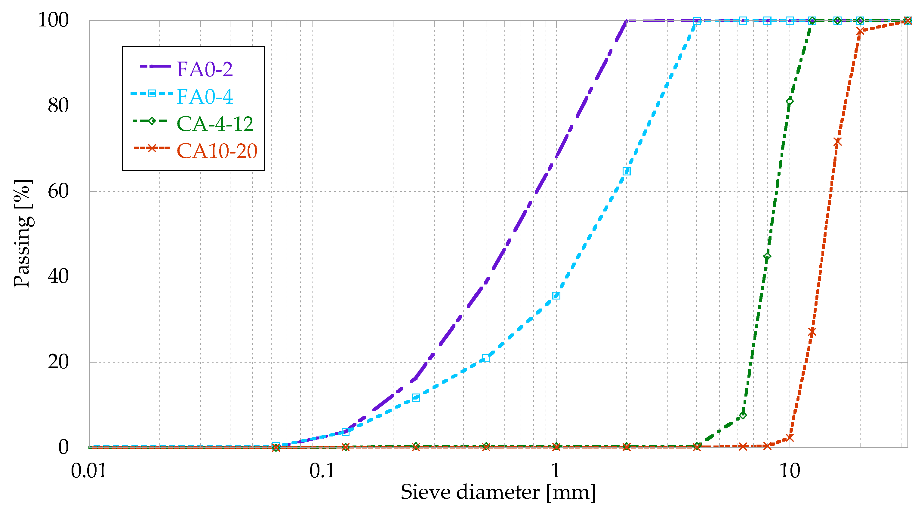
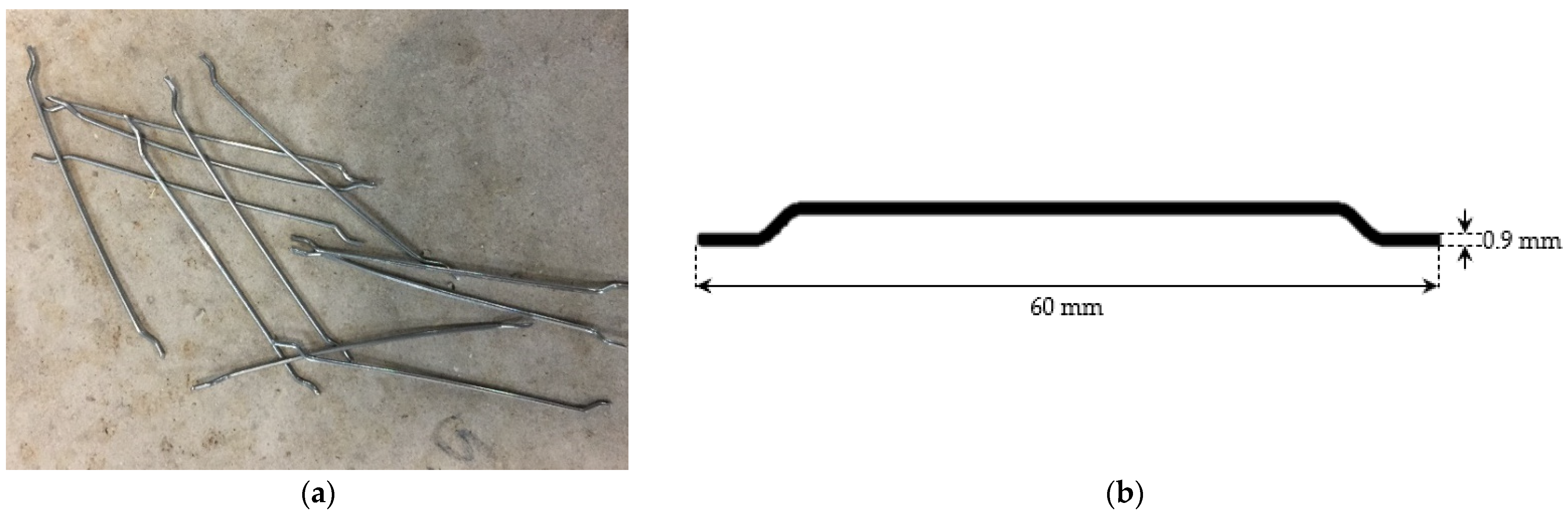
2.1. Materials

Four different fractions of limestone aggregates, two fine aggregates (0/2 mm and 0/4 mm), coded FA0-2 and FA0-4, respectively, and two coarse aggregates (10/20 mm and 4/12 mm), coded CA4-12 and CA10-20, respectively, were selected to manufacture the concrete. Physical properties and grading of these aggregates, obtained according to EN 933-1 [23], are shown in Table 1 and Figure 1, respectively. Cement CEM I 52.5N type was used, according to EN 197-1:2011 [24], with a density of 3120 kg/m3, obtained according to UNE 80103:2013 [25]. The quantity of cement used was 390 kg/m3 and its composition can be seen in Table 2. A superplasticizer additive, Master Ease 5025, was added in the proportion of 1% wt. of cement.
A quantity of 35 kg/m3 of the selected Hooked-end steel fibres was added, with a tensile strength of 1200 MPa, a length of 60 mm and a diameter of 0.9 mm (Figure 2). The concrete mix proportions obtained according to the Fuller method are shown in Table 3.

2.2. Methods

2.2.1. Compressive Strength
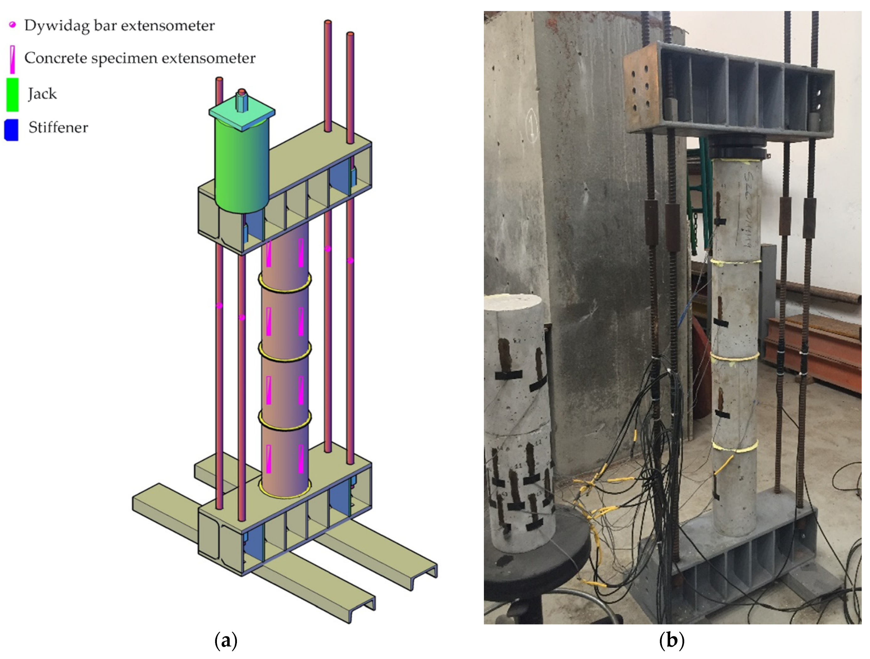
EN 83507:2004 [26] was followed to determine the compressive strength at 24 h, 3, 7 and 28 days. The tested specimens were cubic of 150 × 150 × 150 mm3, cured in a humidity chamber under controlled conditions (20 ± 2 °C and 95 ± 5% humidity).

2.2.2. Creep Test

The specimens manufactured for this test were cylinders with a diameter of 15 cm and a height of 30 cm. Until the time of the test, the specimens were cured in a humidity chamber under controlled conditions (20 ± 2 °C and 95 ± 5% humidity). To determine the creep deformation of the concrete, three strain gauges were installed on each specimen to measure the deformation due to applied load.
For the loading of the specimens, the authors designed a loading gantry that enabled the analysis of the evolution of creep deformation of several specimens simultaneously. In this investigation, four concrete specimens with fibres were loaded in each load frame. These frames were composed of two reaction beams, four Dywidag bars that perform the loading of the specimens, and a spherical hinge that enabled the specimen to be axially loaded, avoiding the introduction of bending stresses (as shown in Figure 3).
The Dywidag bars load the specimens, which are tensed using a 60-ton hollow jack in four load steps, corresponding to 25%, 50%, 75%, and 100% of the stressing strength. To control the stress in the Dywidag bars, it was decided to fit these structural elements by installing two bidirectional extensometers per bar, connected to each other by means of an electronic assembly in a complete Wheatstone bridge [27]. The deformation experienced by the fibre-reinforced concrete specimens is experimentally measured by installing three unidirectional strain gauges in three generatrices at 120° in each specimen. These bands are individually connected with control strain gauges that enable compensation for thermal effects during the test. The connection of the bands is made by means of an electronic mounting in a half Wheatstone bridge [27] (Figure 4).
In order to analyse the creep evolution of the concrete specimens with fibres and obtain the creep curves associated with this type of concrete at different loading ages, the specimens were divided into four groups and each group was tested at four different loading ages. The loading configuration for each specimen is shown in Table 4. The need to submit specimens of different ages, 24 h and 3 d, and 7 d and 28 d, to the same load, arises from the availability of only two loading frames. In one of the loading frames, the analysis of the creep undergone by the specimens loaded at 24 h and 3 d is carried out, and in the other the specimens loaded at 3 d and 28 d. Young specimens (loaded at 1 and 3 days) were loaded at 265 kN (around 80% of the compressive strength at 24 h and 40% at 3 d), while the others (loaded at 7 and 28 days) were loaded at 353 kN (around 50% of the compressive strength at these ages). In the case of 24 h and 3 d age specimens, the load was chosen to be sufficiently representative at 3 d, but to be able to be supported by 24 h age specimens. In the case of 7 and 28 d age specimens, a load of 50% of its compressive strength was considered adequate to see a significant evolution in the concrete.

2.2.3. Modulus of Elasticity

During the loading and unloading of the specimens arranged on each load frame, the following physical magnitudes were monitored: (a) the stress applied by tensioning the diwydag bars; (b) the deformation experienced by the fibre-reinforced concrete specimens. The stress/strain curve of the specimens obtained during their loading and unloading made it possible to obtain the initial and residual modulus of elasticity of FRC for the different ages of loading analysed.

2.2.4. Delayed Elastic Strain

Once the creep test was completed and the load applied to the FRC specimens removed, the evolution over time of the strain undergone by the specimens is monitored. This monitoring makes it possible to evaluate the delayed elastic strain undergone by the specimens after the creep test.

2.2.5. Microscopic Analysis

Microscopic images using a scanning electron microscope (SEM) were obtained of the concrete with fibres used for this study.
Although the scanning electron microscope was used to obtain images at high magnifications of almost all materials, it could also be used in combination with an energy dispersive spectrometer (EDX), which also allows us to know the elements present in specific sections of a sample. For this, a Carl Zeiss EVO MA15 SEM was used, fitted with an Oxford Instruments X-ray detector.

3. Results and Discussion

3.1. Compressive Strength

As starting data for the analysis of the creep undergone by the fibre-reinforced concrete specimens, the compressive strength of the concrete was obtained at the different loading ages. Figure 5 shows the evolution curve of the compressive strength of FRC over time.
Between 3 and 28 days of age of the FRC, it is observed that there is no significant difference, with the greatest evolution occurring in the first 72 h of age.

3.2. Creep Test

Figure 6 shows the evolution of creep deformation over time, differentiating between specimens that were subjected to a load of 15 MPa (24 h and 3 d of age) and those that were subjected to a load of 20 MPa (7 d and 28 d of age). In the following figures, the joint results of each age rage are shown as the average evolution experienced by the two test specimens.
Analysing the evolution of the deformation of the FRC due to the creep episode to which it was subjected during the test, differences in strain rates are observed according to the age in the specimens loaded at 15 and 20 MPa. As can be seen in Figure 6, in the first stage of the creep episode, the deformation of the specimens loaded at a younger age is greater. This is due to the fact that the cement in the younger specimens has not hydrated sufficiently and deforms more in the first days of loading, in agreement with other authors [28].
However, for a loading age of 150 days in the specimens loaded at 15 MPa, and for a loading age of 200 days in the specimens loaded at 20 MPa, there is an inflection point from which the deformations of the specimens loaded at different ages are equalized. This is due to the fact that from high ages onwards, the age of loading is not so relevant since in the long term they are similar. In other words, the effect of the load does not penalise the hydration of the cement in the long term. This tendency of creep evolution to stabilise at high loading ages has been corroborated by other authors [1]. It also coincides with the conclusion reached by other studies that greater creep evolution occurs in the first hours of aging of the reinforced concrete [29].

3.2.1. Proposed Creep Formulation

Comparing the evolution of the creep deformation of the FRC with the theoretical curve reflected in the EHE-08 standard [22], an important divergence is observed. The evolution of creep deformation undergone by FRC specimens loaded 24 h after their manufacture is the one that deviates the most from the theoretical curve defined in the EHE-08 standard. For the rest of the test specimens, loaded at the ages of three, seven and twenty-eight days, there is still a divergence between their experimental behaviour and that predicted by the EHE-08 standard, but this divergence is much smaller. The maximum divergence between experimental and theoretical creep deformation is recorded for the first stage of the creep process to which the FRC specimens have been subjected during the test. Equation (1) shows the formulation proposed by the EHE-08 standard for estimating creep deformation in concrete.
ε c σ ( t , t 0 ) = σ ( t o ) E c , t o + σ ( t o ) · φ H R · β ( f c m ) · β ( t o ) · β c ( t t o ) E c , 28
β ( t 0 ) γ = 1 0 , 1 + t 0 α ( t 0 )
β c ( t t 0 ) γ = ( ( t t 0 ) β H + ( t t 0 ) ) α ( t t 0 )
where:
-
σ(to) is stress on specimens during creep test.
-
Ec,to is the initial modulus of elasticity in specimens.
-
Ec,28 is the modulus of elasticity of the specimens at 28 days.
-
φHR is the coefficient of influence of relative humidity [22].
-
β(fcm) is the coefficient of influence of concrete strength [22].
-
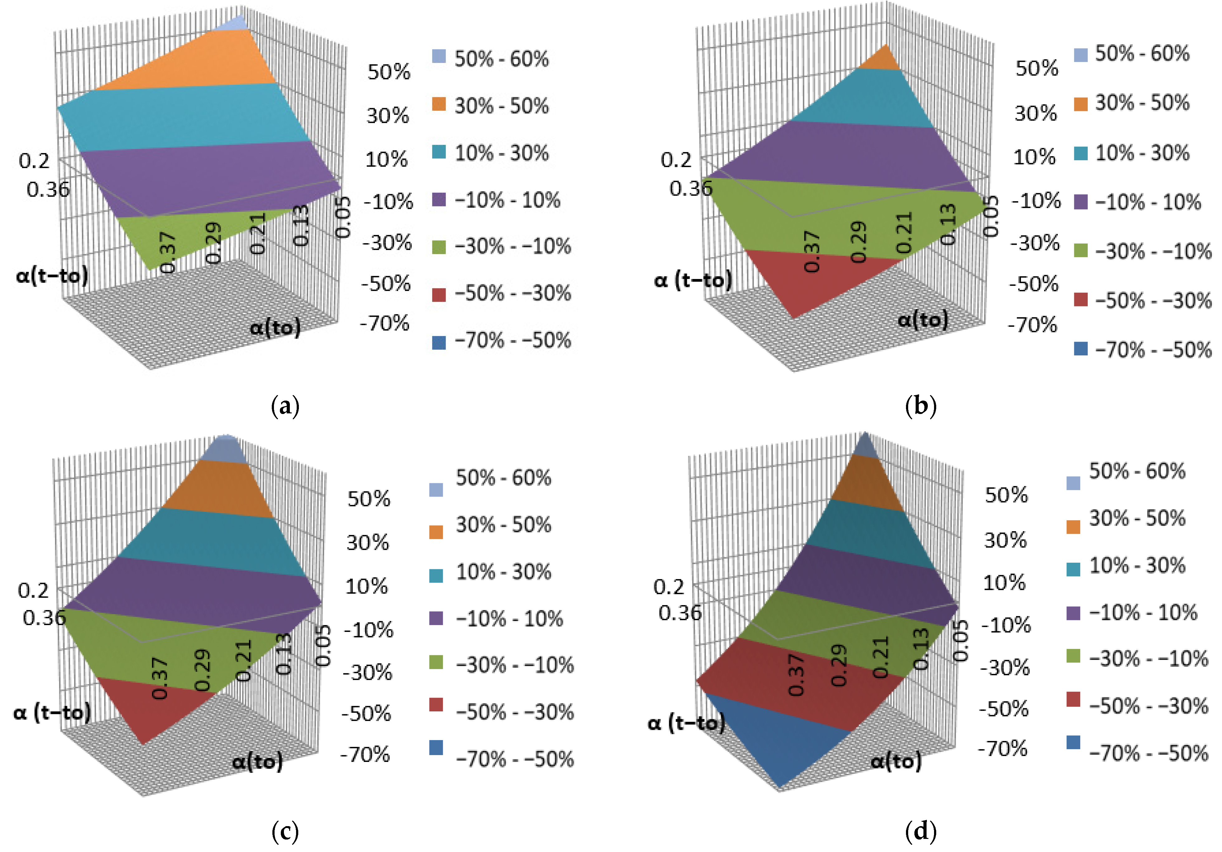
α(t0) is the coefficient associated with the loading age proposed by the authors;
-
α(tt0) is the coefficient associated with the evolution of creep with time proposed by the authors.
Figure 7 shows the evolution of the error of the model proposed by the authors with the variation of the value of the coefficients “α(t0)” and “α(tt0)”, while Figure 8 shows the range of optimal coefficients of the model proposed by the authors to minimize the deviation of the predictive model compared with the experimental results obtained in the laboratory.
To determine the optimal creep coefficients, the authors have scanned all possible combinations of values of these coefficients and have obtained the error of the final proposed formulation for each load age analysed in the study. Figure 8 represents the traces of the interval corresponding to a maximum deviation of 5% for the different ages of FRC loading: (a) green trace for FRC loaded at 24 h; (b) cyan trace for FRC loaded at 3 d; (c) blue trace for FRC loaded at 7 d; (d) pink trace for FRC loaded at 28 days. The optimal interval is taken as the area in which the divergence intervals of less than 5% converge for all the load ages analysed in the creep test. The authors propose the following values for the coefficients associated with the loading age and the evolution of creep with time: α(t0) = 0.13; α(tt0) = 0.39.

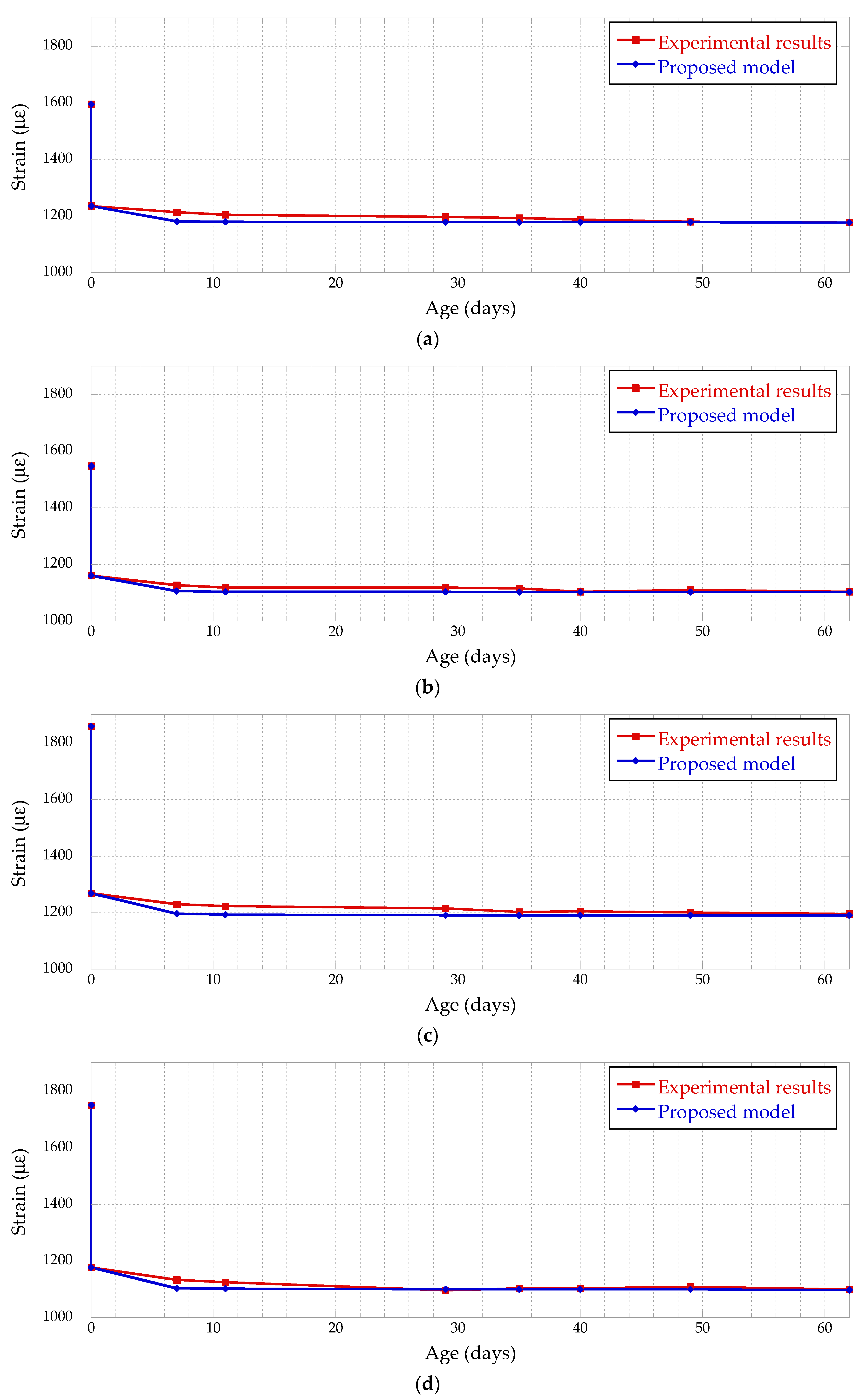
3.2.2. Verification of Creep Formulation

Figure 9 represents the evolution of the deferred creep strain over time. The values obtained in the laboratory (“experimental results”) are compared with the predictive model of the EHE-08 (“normative prediction”) and the predictive model proposed by the authors (“proposed model”).
The normative prediction fits relatively well with the experimental results in FRC loaded at 28 d of age. However, the standard does not accurately reproduce the experimental results at early loading ages of the FRC, especially at 24 h of age. Other authors have already detected discrepancies between standards and experimental creep results [28,30].

3.3. Modulus of Elasticity

The specimens loaded 24 h after their manufacture were subjected to a tension equivalent to 78% of their compressive strength. Figure 10a shows the stress/strain curve of the FRC specimens loaded at 24 h and at 3 d. As expected, for the same compression stress of 15 MPa, the deformation of the loaded specimens at 24 h is much greater than that corresponding to the specimens loaded at 3 d. In the case of the FRC specimens loaded at the age of seven and twenty-eight days, the stress level during the creep test was similar, equivalent to 53 and 47% of their compressive strength respectively. In Figure 10b, we can see the similarity of the stress/strain curves of the specimens loaded at the age of seven and twenty-eight days.
From the analysis of the stress/strain curves of the specimens during their loading, the modulus of elasticity of the FRC is obtained at the time corresponding to the start of the creep test. As expected, and according to the values obtained for the compressive strength of concrete, the value of the modulus of elasticity increases with the age of the concrete, as reflected in Figure 11.
It can be observed that the modulus of elasticity evolves with age in a similar way to the evolution of the compressive strength (Figure 5).
Figure 12 shows the stress/strain curves of the specimens during their unloading.
Once the creep test was completed, the analysis of the stress/strain curves of the specimens during their unloading (Figure 12) makes it possible to obtain the residual modulus of elasticity of the FRC after the 384-day duration of the creep test. In the case of the residual modulus of elasticity of FRC, it is observed that its value decreases with the increase in the loading age of the concrete.
As can be seen in Figure 13, the FRC specimens with the highest stiffness are those that were loaded 24 h after their manufacture.
Performing a comparative analysis of the stress/strain curves of the specimens during their loading with the curves corresponding to their unloading, it can be observed that the influence of the creep of FRC on its deformation behaviour is different for concrete loaded at early age than for concrete loaded with an age greater than 3 d. Whereas in a concrete loaded at an early age, its modulus of elasticity increases after having been subjected to a creep episode, in concrete loaded at an age greater than 3 d, its modulus of deformation remains unchanged (Table 5).
The difference between the initial and residual modulus of elasticity depends on the loading age. Furthermore, the two moduli of elasticity evolve in an inversely proportional way, so early loaded specimens have lower initial modulus of elasticity and higher residual modulus of elasticity.

3.4. Delayed Elastic Strain

Figure 14 shows the evolution of the delayed elastic strain after the creep test. The specimens were monitored for 62 d after the removal of the load.
Analysing the evolution of the delayed elastic strain after the creep test, and confirming the behaviour observed in the analysis of the instantaneous elastic strain when removing the load to which the FRC specimens were subjected, it is observed that the strain of the FRC specimens loaded at an early age is significantly less than that of samples loaded at an age greater than 3 d.
After analysing the data obtained in the laboratory, the authors propose the formulation in Equation (4) to predict the delayed elastic strain of FRC after a creep episode (Figure 15).
ε e = ε e , i + ε e , d = σ E c , t d · ( 1 + 0.14 · ( ( t t d ) ( 1.5 · ( t t d ) ) ) 0.39 )
where:
-
ɛe,i is the instantaneous elastic strain.
-
ɛe,d is the delayed elastic strain.
-
td is the unloading age.
-
Ec,td is the modulus of elasticity of the specimens at unloading age.
It can be observed that the instantaneous deformation is greater when the age of loading of the reinforced concrete is greater. This is due to the increase in the elastic behaviour of the concrete with age.
Furthermore, the proposed model very accurately reproduces the evolution of the deformation after removal of the load, especially the instantaneous strain and the strain produced long term.

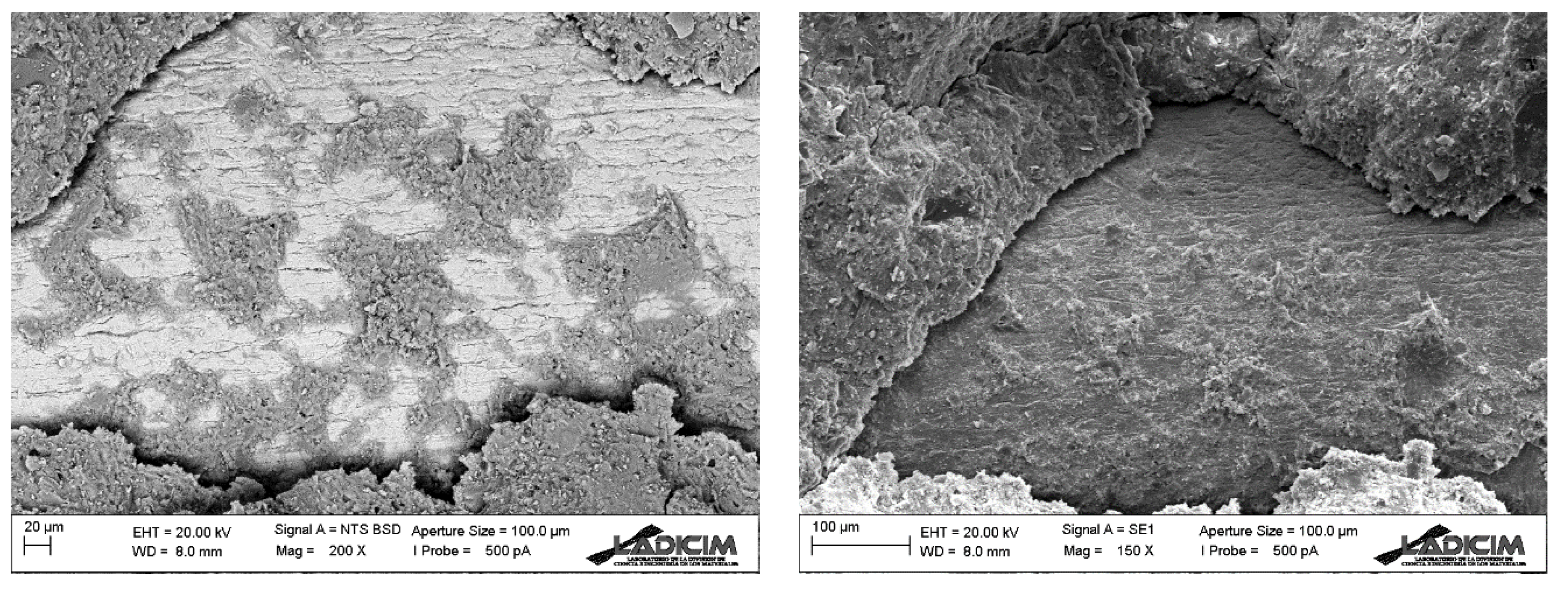
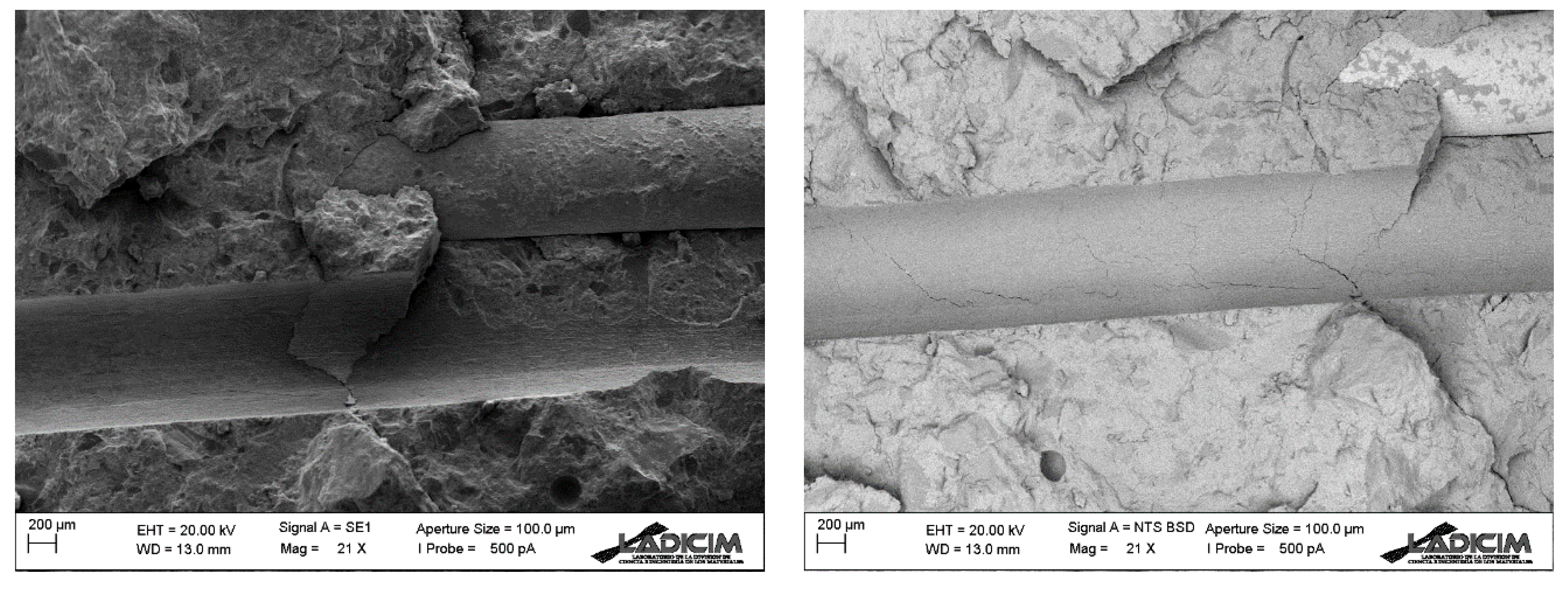
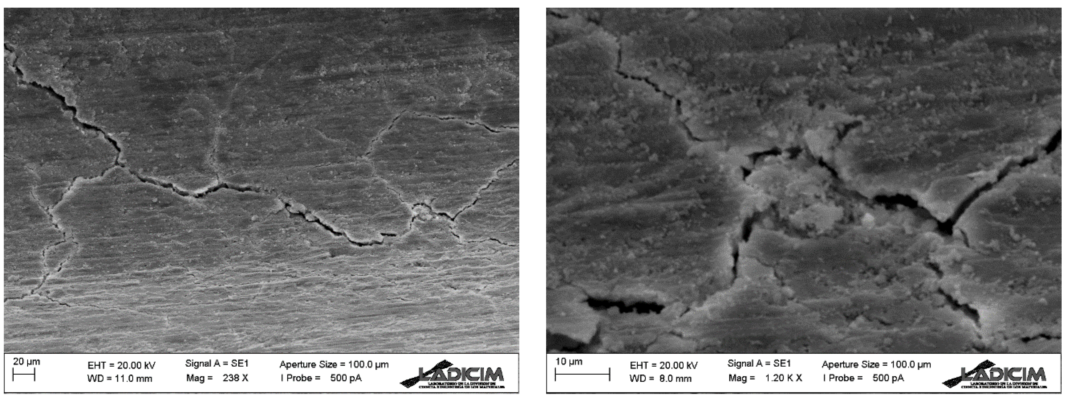
3.5. Microscopic Analysis

In the Figure 16, Figure 17 and Figure 18, the imprint of a fibre that reinforced the concrete and its “bed” can be seen after the mechanical tests were carried out (at different magnitudes).
In Figure 16, two fibres appear to penetrate the concrete. There is paste adhering to the fibres, which is a sign of good bonding between paste and fibres. On the other hand, small cracks can be seen in the microscopic images.
Microscopic images (Figure 16, Figure 17 and Figure 18) show that the mechanical tests do not cause the fibres to fissure or deform, but that the metal fibres appear detached and hardly deformed. In addition, a nodule is seen to form at the junction of several microcracks.

4. Conclusions

From this work, the following conclusions can be drawn:
-
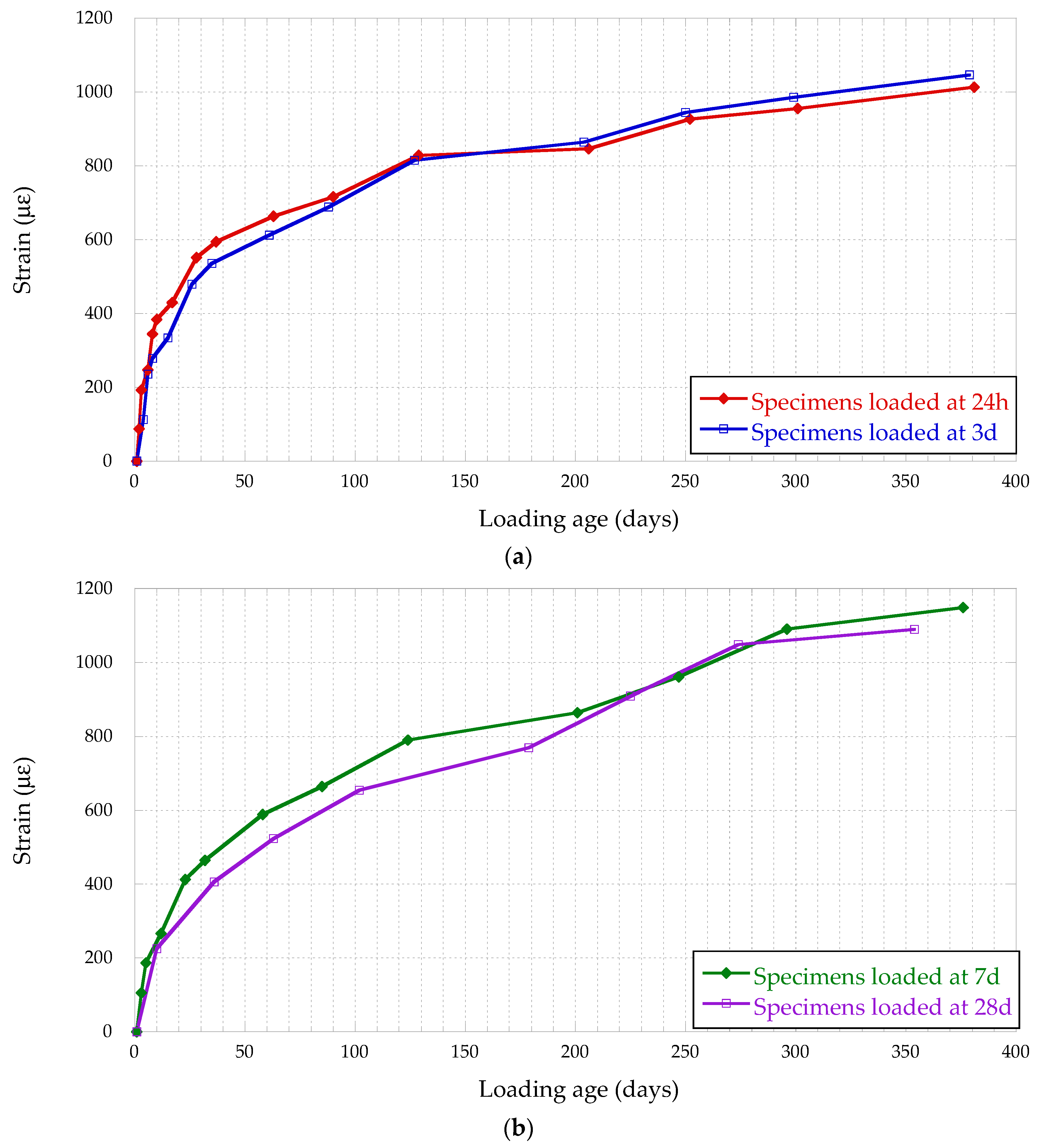
From the analysis of the creep strain undergone by the FRC specimens analysed during the test, two stages can be distinguished: (a) in a first stage, the creep deformation of the specimens loaded at an earlier age shows a greater strain; (b) in the second stage, the creep strain is equalized for the different loading ages.
-
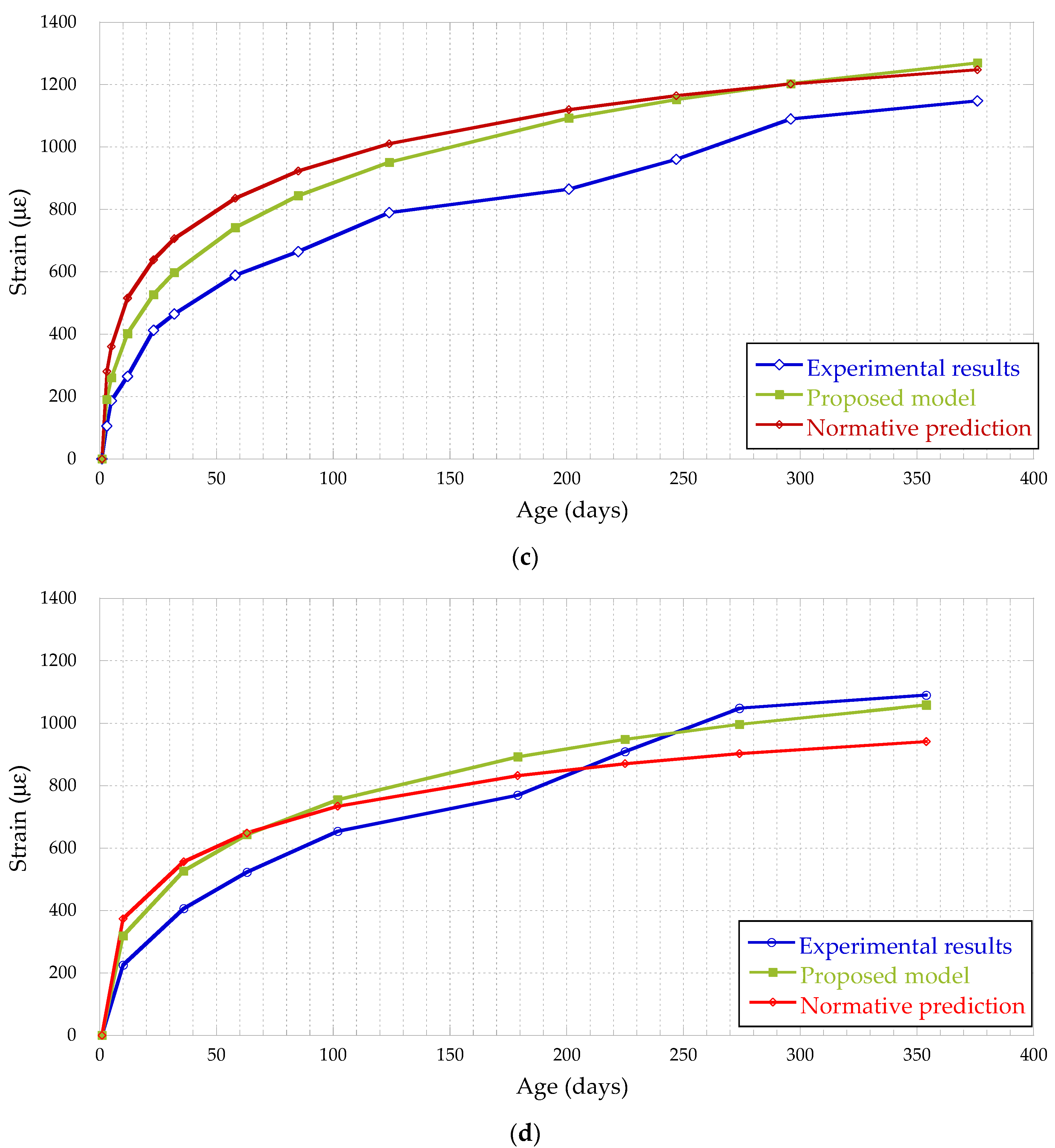
The strain undergone by FRC specimens loaded at an earlier age, 24 h after their manufacture, shows a much lower level than predicted by the formulation proposed by the EHE-08 standard. In the case of the specimens loaded at the ages of three, seven and twenty-eight days, the strain is also less than that foreseen in the EHE-08 standard, although the difference is not so high.
-
The authors propose an adjustment of the creep coefficients proposed in the EHE-08 equation associated with the loading age β(t0) and the evolution of the creep in time βc(tt0).
-
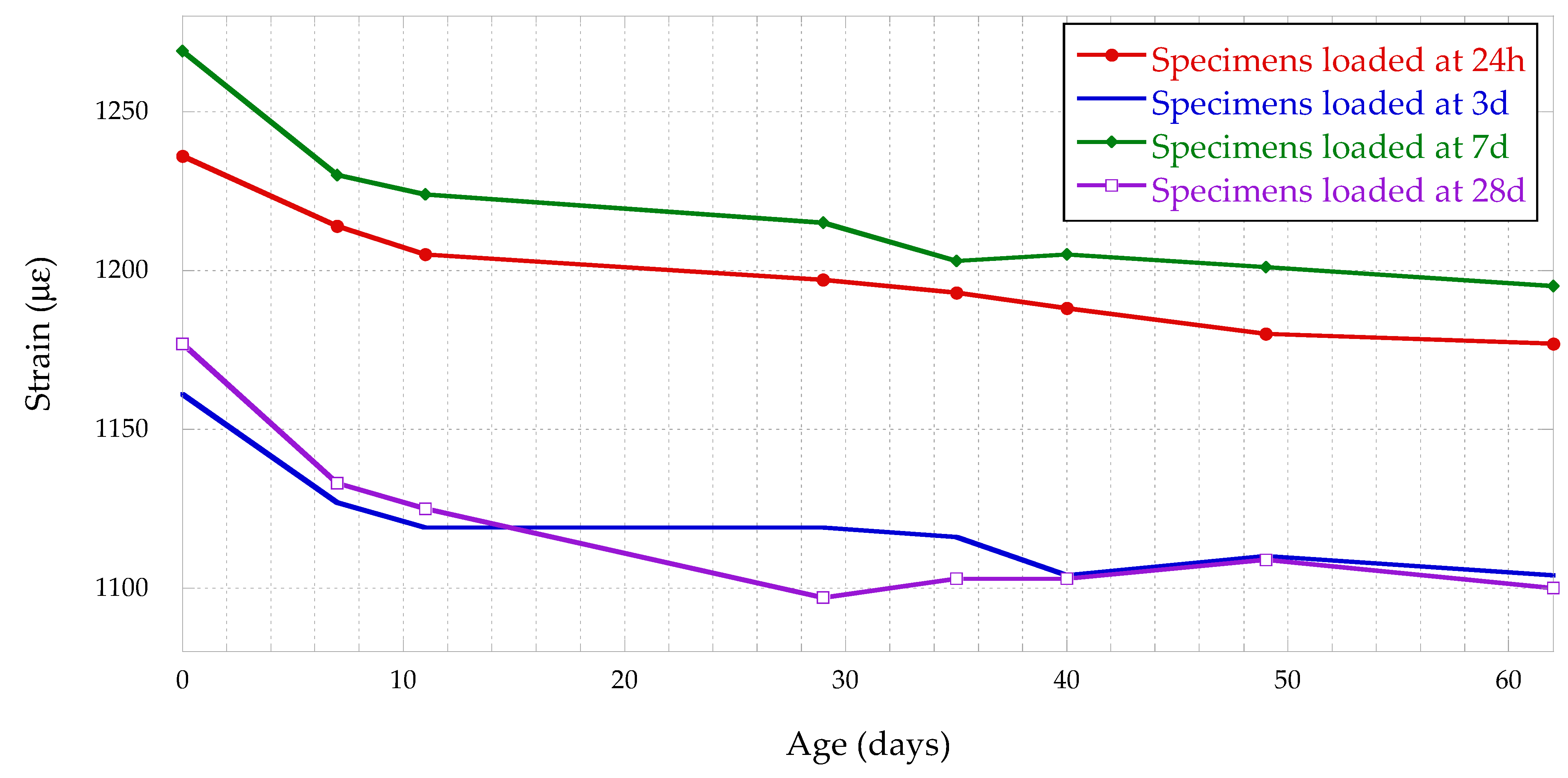
From a comparative analysis of the stress/strain curves of the FRC specimens during their loading and unloading, it can be concluded that the FRC loaded at an earlier age stiffens after a creep episode.
-
Once the results of the creep test of FRC loaded at different ages was analysed, it could be concluded that FRC had better creep behaviour than conventional concrete.
-
Analysing the evolution of the delayed elastic deformation of the FRC specimens after the end of the creep test, it is concluded that, the FRC loaded at an earlier age, undergoes less deformation.
-
The authors propose a formulation for the analysis of the delayed elastic deformation of FRC after a creep episode.

Author Contributions

Conceptualization, L.G., Á.G., J.R. and C.T.; methodology L.G. and Á.G.; validation J.R. and C.T. formal analysis, L.G., Á.G. and C.T.; investigation, L.G. and Á.G.; resources, J.R. and C.T.; writing—original draft preparation, L.G. and Á.G.; writing—review and editing, J.R. and C.T.; supervision, C.T.; project administration, J.R. and C.T.; funding acquisition, J.R. and C.T. All authors have read and agreed to the published version of the manuscript.

Funding

This research was co-funded by Cantabria Government, thought the grant for Industrial Doctoral Program (CVE-2020-8540) and by Ministry of Economy and Competitiveness of Spain, through S2C project (2017-6013-3).

Institutional Review Board Statement

Not applicable.

Informed Consent Statement

Not applicable.

Data Availability Statement

Not applicable.

Acknowledgments

The authors would like to thank: LADICIM, the Laboratory of Materials Science and Engineering of the University of Cantabria, for making the facilities used in this research available to the authors, ArcelorMittal for providing the fibres and BASF for providing the additive to manufacture the reinforced concrete. The authors would like to thank the “industrial doctoral” grant program of the Government of Cantabria for their support.

Conflicts of Interest

The authors declare no conflict of interest.

References

  1. Tosic, N.; Aidarov, S.; De la Fuente, A. Systematic Review on the Creep of Fiber-Reinforced Concrete. Materials 2020, 13, 5098. [Google Scholar] [CrossRef] [PubMed]
  2. Ríos, J.D.; Cifuentes, H.; Blasón, S.; López-Aenlle, M.; Martínez-De La Concha, A. Flexural fatigue behaviour of a heated ultra-high-performance fibre-reinforced concrete. Constr. Build. Mater. 2021, 276, 122209. [Google Scholar] [CrossRef]
  3. Atea, R.S. A Case Study On Concrete Column Strength Improvement with Different steel fibers and polypropylene fibers. J. Mater. Res. Technol. 2019, 8, 6106–6114. [Google Scholar] [CrossRef]
  4. Saba, A.M.; Khan, A.H.; Akhtar, M.N.; Khan, N.A.; Rahimian Koloor, S.S.; Petrů, M.; Radwan, N. Strength and flexural behavior of steel fiber and silica fume incorporated self-compacting concrete. J. Mater. Res. Technol. 2021, 12, 1380–1390. [Google Scholar] [CrossRef]
  5. Banjara, N.K.; Ramanjaneyulu, K. Experimental and numerical study on behaviour of HSFRC overlay strip strengthened flexural deficient RC beams. Eng. Struct. 2019, 198, 109561. [Google Scholar] [CrossRef]
  6. Norambuena-Contreras, J.; Thomas, C.; Borinaga-Treviño, R.; Lombillo, I. Influence of recycled carbon powder waste addition on the physical and mechanical properties of cement pastes. Mater. Struct. 2016, 49, 5147–5159. [Google Scholar] [CrossRef]
  7. Sainz-Aja, J.; Gonzalez, L.; Thomas, C.; Rico, J.; Polanco, J.; Carrascal, I.; Setién, J. Effect of Steel Fibre Reinforcement on Flexural Fatigue Behaviour of Notched Structural Concrete. Materials 2021, 14, 5854. [Google Scholar] [CrossRef] [PubMed]
  8. Shi, J.X.; Ran, Z.H. Calculation of Creep Effect of Extradosed Cable-stayed bridge based on Midas Civil. Mater. Sci. Eng. 2018, 423, 012113. [Google Scholar] [CrossRef]
  9. Bazant, Z.; Asce, H.; Yu, Q.; Li, G.-H. Excessive Long-Time Deflections of Prestressed Box Girders. I: Record-Span Bridge in Palau and Other Paradigms. J. Struct. Eng. 2012, 138, 676–686. [Google Scholar] [CrossRef] [Green Version]
  10. Mangat, P.S.; Azari, M.M. Compression creep behaviour of steel fibre reinforced cement composites. Mater. Struct. 1986, 19, 361–370. [Google Scholar] [CrossRef]
  11. Nakov, D.; Mark, P. Experimental and Analytical Analysis of Creep of Steel Fibre Reinforced Concrete. Period. Polytech. Civ. Eng. 2017, 62. [Google Scholar] [CrossRef] [Green Version]
  12. Błyszko, J. Comparative Analysis of Creep in Standard and Fibre Reinforced Concretes under different Load Conditions. Procedia Eng. 2017, 193, 478–485. [Google Scholar] [CrossRef]
  13. Zhang, J. Modeling of the influence of fibers on creep of fiber reinforced cementitious composite. Compos. Sci. Technol. 2003, 63, 1877–1884. [Google Scholar] [CrossRef]
  14. Zhao, Q.; Yu, J.; Geng, G.; Jiang, J.; Liu, X. Effect of fiber types on creep behavior of concrete. Constr. Build. Mater. 2016, 105, 416–422. [Google Scholar] [CrossRef]
  15. Madureira, E.L.; Fontes, B.V. Temperature influence on creep of reinforced concrete. Revista IBRACON de Estruturas e Materiais 2020, 13. [Google Scholar] [CrossRef]
  16. Jin, S.-S.; Cha, S.-L.; Jung, H.-J. Improvement of concrete creep prediction with probabilistic forecasting method under model uncertainty. Constr. Build. Mater. 2018, 184, 617–633. [Google Scholar] [CrossRef]
  17. Reddy, D.H.; Ramaswamy, A. Experimental and numerical modeling of creep in different types of concrete. Heliyon 2018, 4, e00698. [Google Scholar] [CrossRef] [PubMed] [Green Version]
  18. Liu, R.; Ye, H.; Liu, Y.; Zhao, H.; Correia, J.A.F.O.; Xin, H. Numerical simulation of concrete creep behaviour using integral creep algorithm with alternating stresses. Structures 2021, 29, 1979–1987. [Google Scholar] [CrossRef]
  19. Havlásek, P.; Šmilauer, V.; Dohnalová, L.; Sovják, R. Shrinkage-induced deformations and creep of structural concrete: 1-year measurements and numerical prediction. Cem. Concr. Res. 2021, 144, 106402. [Google Scholar] [CrossRef]
  20. American Association of State Highway and Transportation Officials (AASHTO). AASHTO LRFD Bridge Design Specifications Chemistry; AASHTO: Washington, DC, USA, 2012. [Google Scholar]
  21. A.C. Institute. Creep and Shrinkage. Guide for Modeling and Calculating Shrinkage and Creep in Hardened Concrete. ACI Committee 209. 2008. Available online: http://www.civil.northwestern.edu/people/bazant/PDFs/Papers/R21.pdf (accessed on 1 December 2021).
  22. Ministerio de Fomento, Gobierno de España. EHE-08. Instrucción de Homigón Estructural; Ministerio de Fomento: Madrid, Spain, 2008; pp. 175–177. [Google Scholar]
  23. GEN, E.N. 933-1:2012; Tests for Geometrical Properties of Aggregates-Part 1: Determination of Particle Size Distribution-Sieving Method. Spanish Association for Standardisation, UNE: Madrid, Spain, 2012.
  24. CEN, EN 197-1; Cement Part 1: Composition, Specifications and Conformity Criteria for Common Cements. Spanish Association for Standardisation, UNE: Madrid, Spain, 2011.
  25. CEN, EN 80103:2013; Test Methods of Cements. Physical Analysis. Actual Density Determination. Spanish Association for Standardisation, UNE: Madrid, Spain, 2013.
  26. CEN, EN 83507; Concrete with Fibres. Testing in Compression. Spanish Association for Standardisation, UNE: Madrid, Spain, 2004.
  27. William, F.R.; James, W.D. Experimental Stress Analysis; McGraw-Hill Book Company: New York, NY, USA, 1978. [Google Scholar]
  28. Delsaute, B.; Torrenti, J.-M.; Staquet, S. Modeling basic creep of concrete since setting time. Cem. Concr. Compos. 2017, 83, 239–250. [Google Scholar] [CrossRef]
  29. Altoubat, S. Early Age Stresses and Creep-Shrinkage Interaction of Restrained Concrete. Ph.D. Thesis, University of Illinois Urbana-Champaign, Champaign, IL, USA, 2000. [Google Scholar]
  30. Landsberger, G.A.; Gomez, J. Evaluación de las Deformaciones por Fluencia del Hormigón Autocompactante; JSSN 008-8919, Nº927; Cemento Hormigón: Valencia, Spain, 2008; pp. 42–52. [Google Scholar]
Figure 1. Grading curve of the aggregates used.
Applsci 12 00257 g001
Figure 2. Hooked-end fibres used. (a) photograph; (b) schematic diagram.
Applsci 12 00257 g002
Figure 3. Test gantry configuration. (a) Schematic drawing; (b) photograph.
Applsci 12 00257 g003
Figure 4. Electronic assembly of sensors: (a) full Wheatstone bridge; (b) half Wheatstone bridge.
Applsci 12 00257 g004
Figure 5. Evolution of the compressive strength of FRC.
Applsci 12 00257 g005
Figure 6. Evolution of creep deformation undergone by FRC: (a) specimens loaded at 15 MPa; (b) specimens loaded at 20 MPa.
Applsci 12 00257 g006
Figure 7. Analysis of the error induced by the variation of the exponent of the creep coefficients α(t0) and α(tt0) in the model proposed by the authors to determine the creep strain undergone by FRC: (a) FRC specimens loaded at 24 h (a); at 3 d (b); at 7 d (c); and at 28 d (d).
Applsci 12 00257 g007
Figure 8. Optimization of the coefficients “α(t0)” and “α(tt0)” of the model proposed by the authors for calculating the creep strain of FRC.
Applsci 12 00257 g008
Figure 9. Creep deformation undergone by FRC specimens: FRC loaded at 24 h (a); (b) 3 d; (c) 7 d; (d) 28 d.
Applsci 12 00257 g009aApplsci 12 00257 g009b
Figure 10. Tension-deformation curve during loading of the specimens: (a) FRC specimens loaded at 15 MPa; (b) FRC specimens loaded at 20 MPa.
Applsci 12 00257 g010
Figure 11. Evolution of the modulus of elasticity of FRC with age.
Applsci 12 00257 g011
Figure 12. Stress/strain curve during the unloading of the specimens: (a) FRC specimens loaded at 15 MPa; (b) FRC specimens loaded at 20 MPa.
Applsci 12 00257 g012
Figure 13. Evolution of the modulus of elasticity of FRC with its loading age.
Applsci 12 00257 g013
Figure 14. Evolution of the delayed elastic strain of FRC after a creep episode.
Applsci 12 00257 g014
Figure 15. Evolution of the elastic strain of FRC after a creep episode. Experimental strain versus strain predicted by the model proposed by the authors: FRC specimens loaded at (a) 24 h; (b) 3 d; (c) 7 d; (d) 28 d.
Applsci 12 00257 g015
Figure 16. Fibre (left) and “bed” fibre (right) at 21×.
Applsci 12 00257 g016
Figure 17. Fibre “bed” at 238× (left) and 1200× (right).
Applsci 12 00257 g017
Figure 18. Fibre “bed” at 200× (left) and 150× (right).
Applsci 12 00257 g018
Table 1. Physical properties of the limestone aggregates.
Fraction of AggregateAbsorption [wt.%]Density [kg/m3]Sand Equivalent
FA0-20.492690>75
FA0-40.492690>80
CA4-120.542700-
CA10-200.542680-
Table 2. Chemical composition of the cement used.
Fe2O3CaOSiO2Al2O3MgOTiO2SO3K2OOthers
Compound [wt.%]3.3866.6017.814.791.300.204.490.78<0.5
Table 3. Concrete mix proportions.
MaterialMix [kg/m3]
FA0-2480
FA0-4480
CA4-12480
CA10-20480
Cement390
Water 165
Additive Master Ease 50253.9 (1% wt. cement)
Fibres35
w/c0.45
Table 4. Configuration of test load.
Specimen CodeGroupLoading Age [d]Test Load [kN]Test Stress [MPa]
CF-11126515
CF-21126515
CF-32326515
CF-42326515
CF-53735320
CF-63735320
CF-742835320
CF-842835320
Table 5. Evolution of the modulus of elasticity of FRC after a creep episode. Initial “Eo” and residual “Er” modulus of elasticity.
Loading Age (d)Eo (GPa)Er (GPa)
121.91341.712
333.50038.842
733.66733.904
2836.10034.918
Publisher’s Note: MDPI stays neutral with regard to jurisdictional claims in published maps and institutional affiliations.

