
Unmanned Aerial Traffic Management System Architecture for U-Space In-Flight Services


Abstract
Featured Application
Abstract
1. Introduction
2. Background
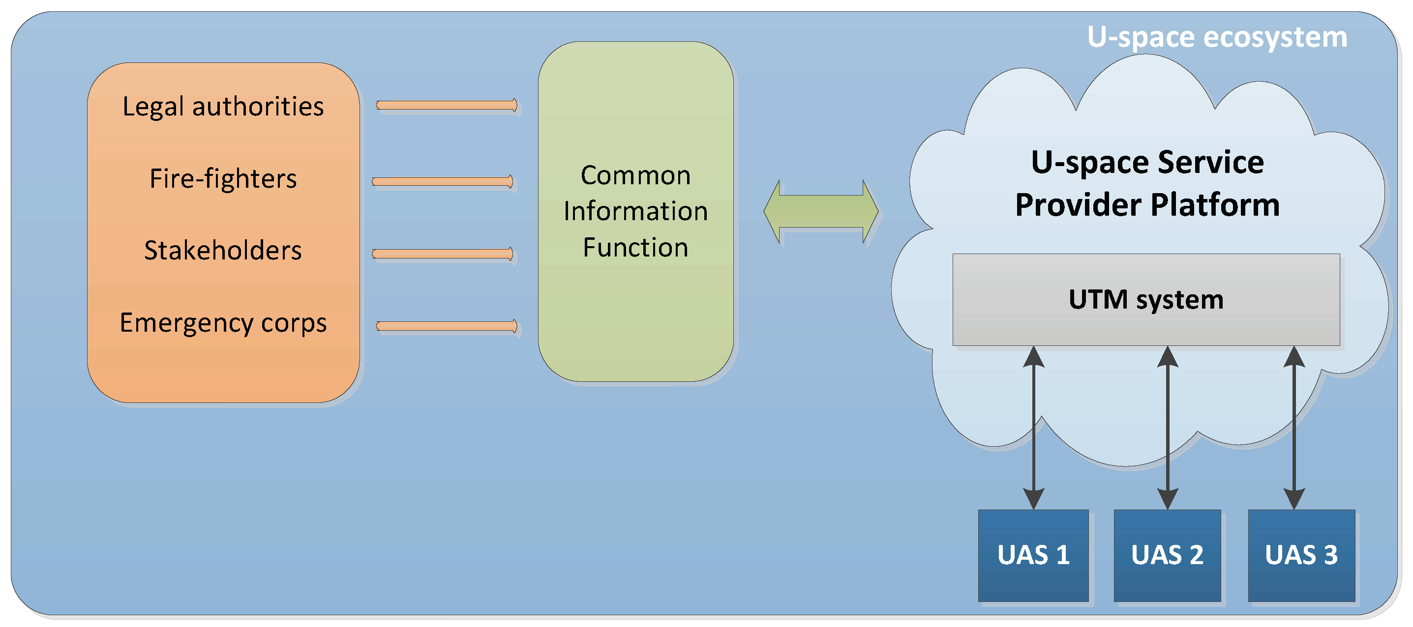
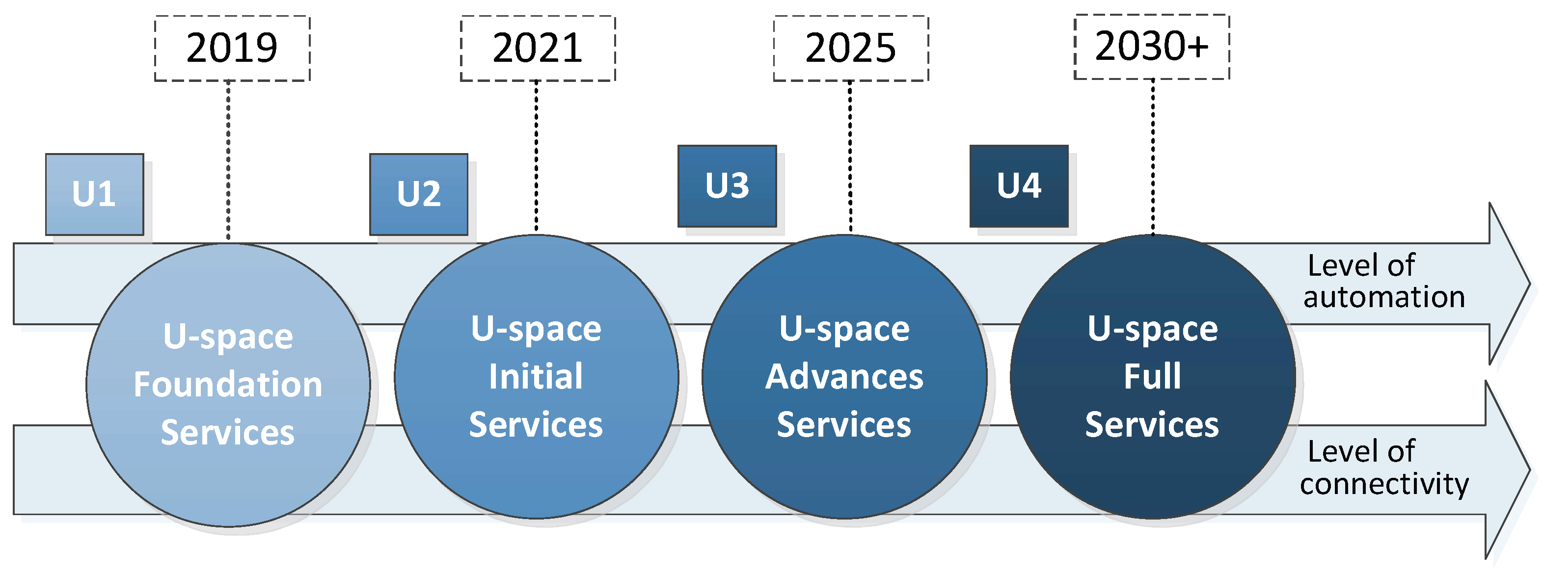
2.1. U-Space
- Pre-flight services are those related with the functionalities needed to prepare and schedule a UAS operation. The vehicle and the operator need to register (E-registration), and the initial flight plan has to be handled before being accepted (Flight planning management). Then, the pilot may get assistance through information about predefined restricted areas (Pre-tactical geofencing) and the resolution of possible conflicts before flying (Strategic deconfliction).
- In-flight services deal with the functionalities required to handle the operation after the UAS flight has started. This means the possibility to update the operator (Tactical geofencing) or the UAS itself (Dynamic geofencing) with geofencing information during the flight, and to track the current position and predicted trajectory for each UAS (Tracking). This updated information is then used to create a situation of the airspace (Monitoring) and to generate warnings and contingency actions under possible threats (Emergency management). Alternative plans could also be suggested in-flight to maintain the required separation between aircraft and with geofences (Tactical deconfliction).
- There are other services that could be used either before flying or during the flight. These are functionalities that aim to provide identification (E-identification), weather forecasts (Weather Information), or more generic information (Drone Aeronautical Information Management), to create an interface with the ATC (Procedural Interface with ATC and Collaborative interface with ATC), and to control and manage the UAS density in the airspace (Dynamic Capacity Management).
2.2. Related Work
3. Design Framework
3.1. Guidelines for System Design
- Digital. The process of system digitization consists of making the communication between the different actors and components digital, and introducing automated decision-making procedures. This is a key aspect in UTM to reduce the operators’ workload in an efficient and secure manner. Moreover, it enables the real-time exchange of data between the relevant parties for situation awareness and an easier integration of the UTM services.
- Flexible and modular. A UTM architecture should be flexible and adaptable to incorporate new actors (e.g., stakeholders) and functionalities (e.g., services), as they appear. Besides, the system should be modular, i.e., made of composable and reusable modules, in order to ease the process of creating more complex functionalities.
- Scalable. A scalable architecture is needed to grow with new actors and services. In order to achieve that, not only is the aforementioned modularity desirable, but also a paradigm with distributed responsibilities, rather than the obsolete scheme with a centralized ATC.
- Safe and secure. These two features are top priorities in any UTM ecosystem. In this sense, the system should know who is flying each unmanned aircraft, where they are flying (or intend to fly) to, and whether they are conforming (or not) to mandatory operating requirements.
- Automated. A UTM system providing automated services to assist the UAS operators will be more efficient and secure. Therefore, the system should provide support through automated functionalities for flight planning, monitoring, and real-time deconfliction, in order to ensure safe operations for both manned and unmanned aircraft.
- Open-source. The use of open-source technologies is preferable, as they offer a global approach towards creating and evolving the necessary services and protocols for scalable operations. Moreover, open-source components can speed up the development and the deployment of UTM services.
3.2. Robot Operating System
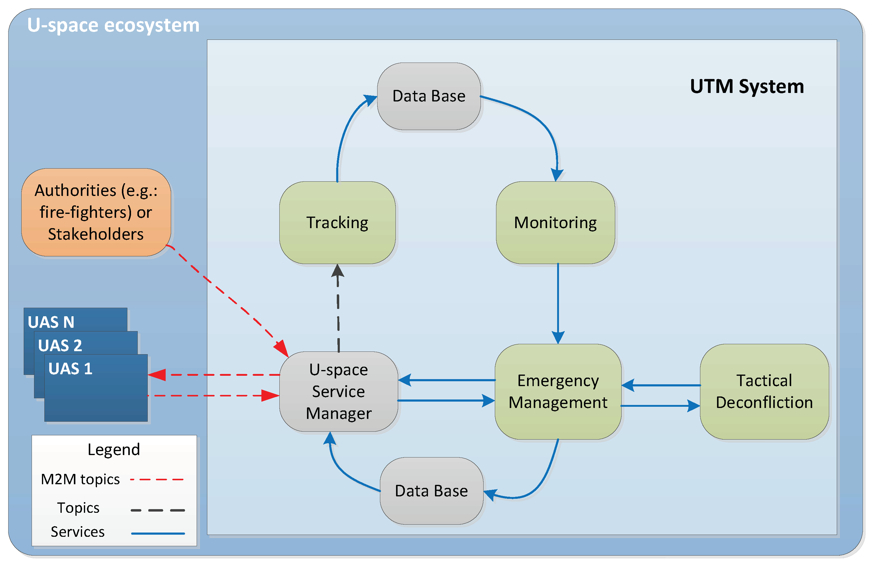
4. UTM System Architecture
4.1. U-Space Service Manager
4.2. Data Base
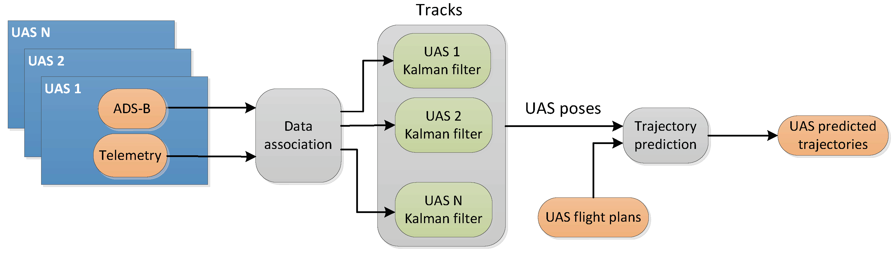
4.3. Tracking
4.4. Monitoring
4.5. Emergency Management
4.6. Tactical Deconfliction
4.7. Discussion
- Tracking. This service is supposed to consider cooperative and non-cooperative UAS, but our current implementation only manages cooperative UAS. This is because we have focused on enabling automated decision-making for the operating UAS, which makes no sense for non-cooperative vehicles. Those should be treated as uncontrollable intruders (i.e., threats) in the airspace. However, our Tracking module does have the capability to update and record data in real time from different sources. Other services can also access these data through the DB module if needed.
- Monitoring. As in the previous case, our current implementation does not consider non-cooperative UAS. We did not establish a specific communication link to provide traffic information to the UAS operators either, though this could be easily done through the USM. However, our Monitoring module does accomplish all the other expected functionalities, i.e., it detects and alerts in real time about conflicts related to flight non-conformances, geofences, and inter-UAS separation.
- Emergency Management. This service is expected to provide the UAS operators with notifications about alerts and any other emergency assistance. Besides, our EM module includes automated decision-making capabilities, in order to manage threats in real time by proposing safe and optimal actions to the UAS.
- Tactical Deconfliction. Although this service is supposed to provide deconfliction information to the UAS operators through the USM, in our scheme this role is played by the EM module. This is because the automated decision-making capability is implemented in the EM module, which uses the TD module to get support generating possible alternative plans. Then, the EM is the one in charge of deciding the best option for real-time deconfliction.
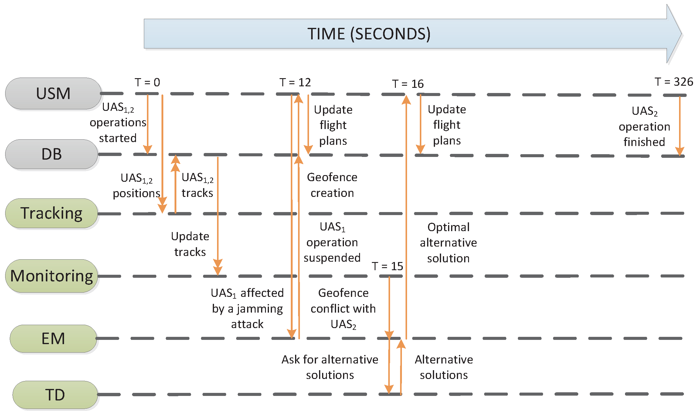
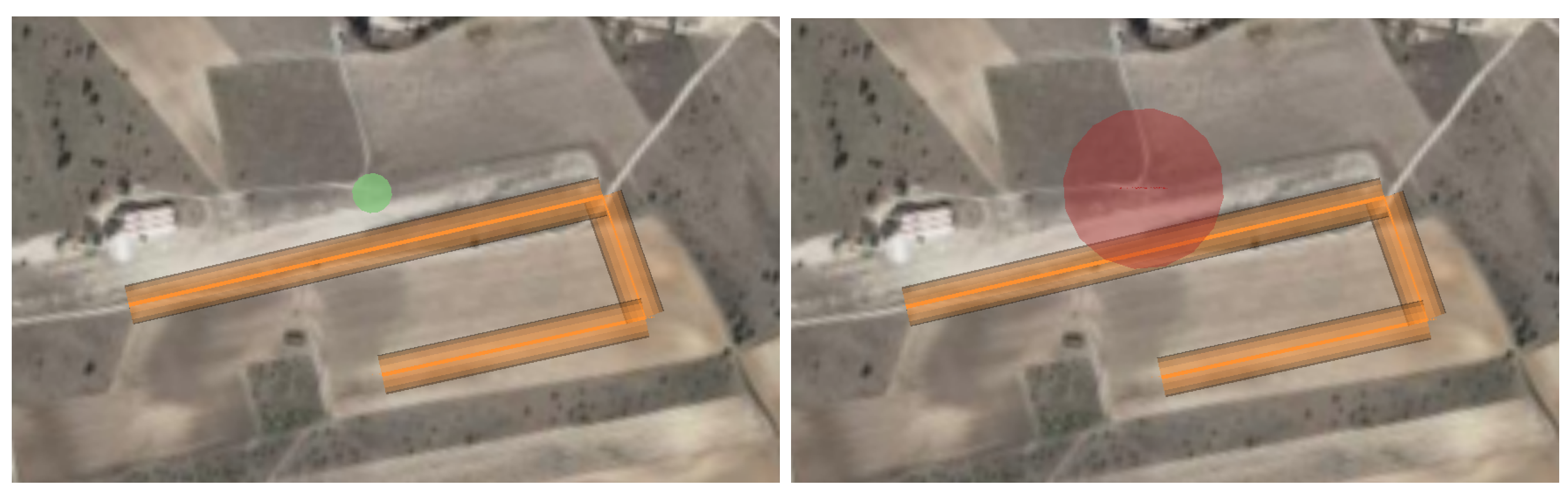
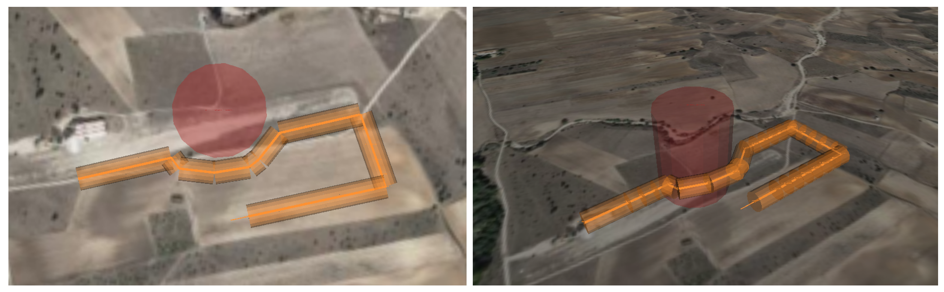
5. Experiments
5.1. Use Cases Definition
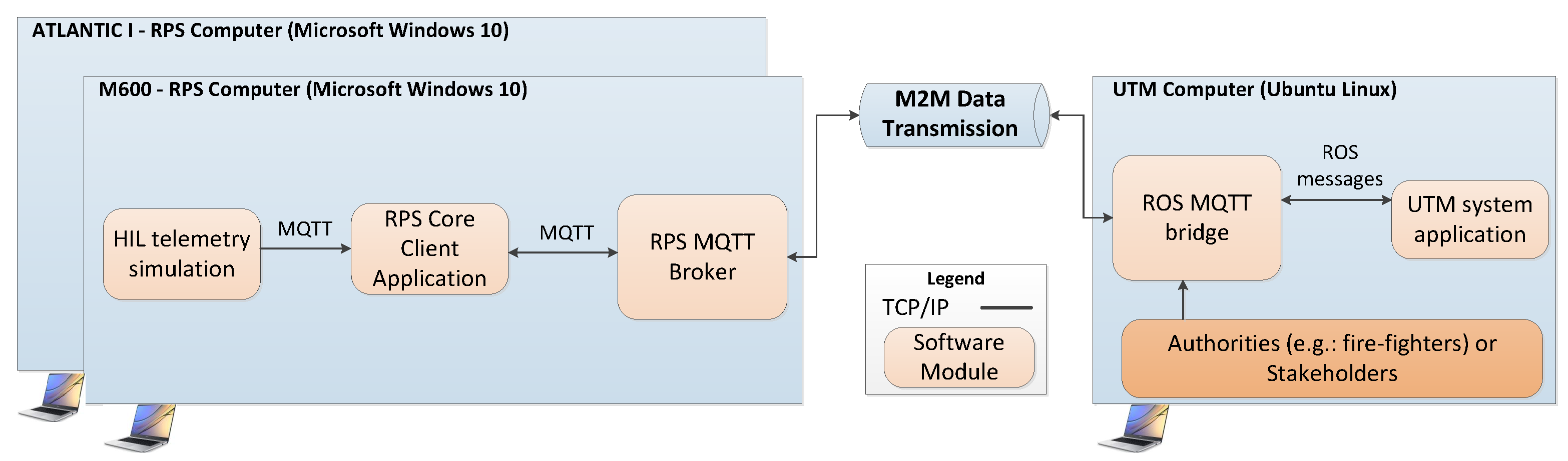
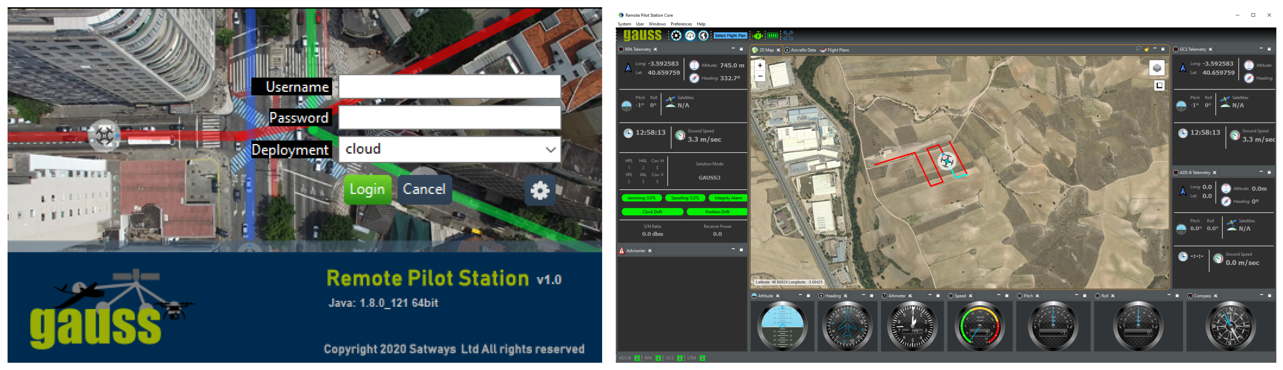
5.2. Experimental Setup
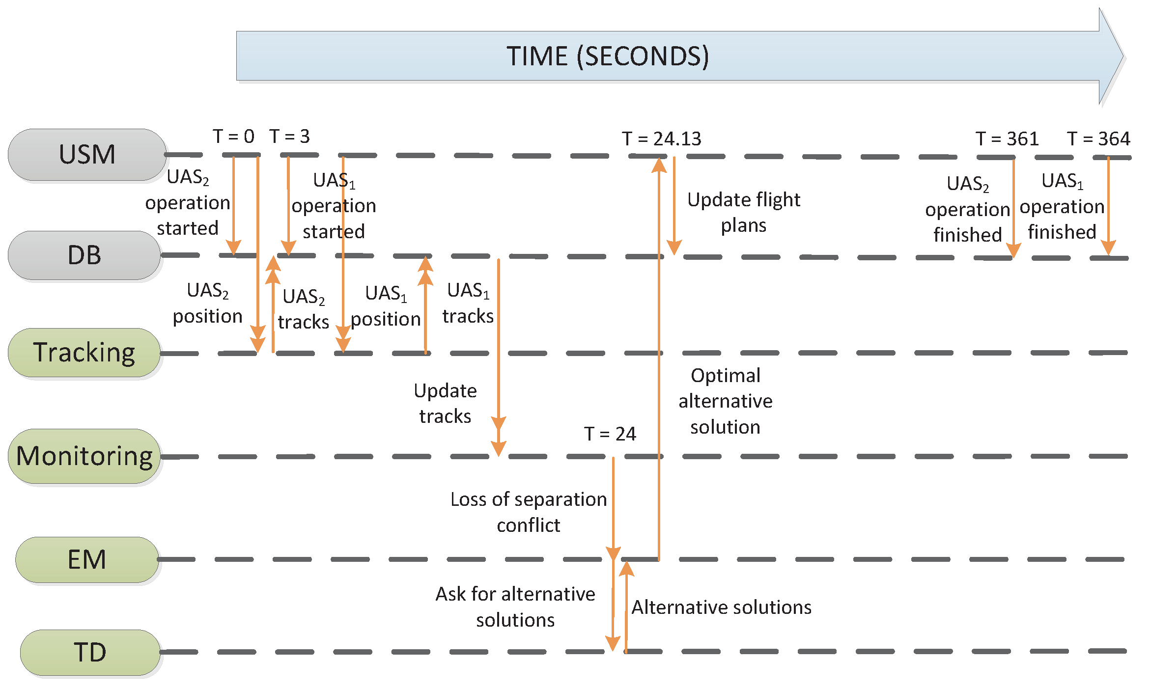
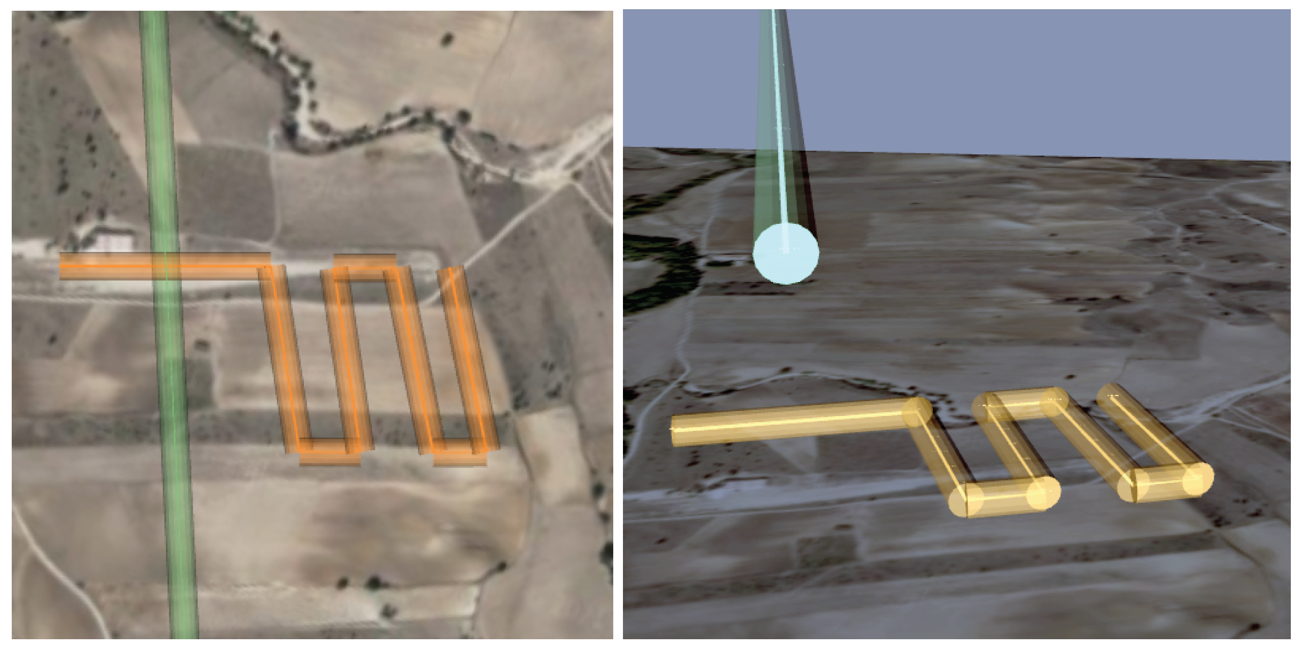
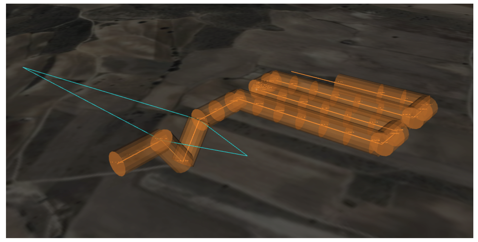
5.3. Results
6. Conclusions
Author Contributions
Funding
Institutional Review Board Statement
Informed Consent Statement
Data Availability Statement
Conflicts of Interest
Abbreviations
| ADS-B | Automatic Dependent Surveillance Broadcast |
| ATC | Air Traffic Control |
| ATM | Air Traffic Management |
| DB | Data Base |
| DDS | Data Distribution Service |
| EASA | European Aviation Safety Agency |
| EM | Emergency Management |
| GNSS | Global Navigation Satellite System |
| GUTMA | Global UTM Association |
| HITL | Hardware-In-The-Loop |
| ICAO | International Civil Aviation Organization |
| JSON | JavaScript Object Notation |
| MQTT | Message Queuing Telemetry Transport |
| NASA | National Aeronautics and Space Administration |
| NTP | Network Time Protocol |
| QoS | Quality of Service |
| ROS | Robot Operating System |
| RPS | Remote Pilot Station |
| RTPS | Real-Time Publish-Subscribe |
| SITL | Software-In-The-Loop |
| TD | Tactical Deconfliction |
| UAS | Unmanned Aircraft System |
| USM | U-space Service Manager |
| UTM | Unmanned aerial system Traffic Management |
| VLL | Very Low Level |
References
- SESAR. European Drones Outlook Study; Technical Report; SESAR: Brussels, Belgium, 2016. [Google Scholar] [CrossRef]
- Aurambout, J.P.; Gkoumas, K.; Ciuffo, B. Last mile delivery by drones: An estimation of viable market potential and access to citizens across European cities. Eur. Transp. Res. Rev. 2019, 11, 1–21. [Google Scholar] [CrossRef]
- Capitan, J.; Merino, L.; Ollero, A. Cooperative Decision-Making Under Uncertainties for Multi-Target Surveillance with Multiples UAVs. J. Intell. Robot. Syst. 2016, 84, 371–386. [Google Scholar] [CrossRef]
- Sanchez-Cuevas, P.J.; Gonzalez-Morgado, A.; Cortes, N.; Gayango, D.B.; Jimenez-Cano, A.E.; Ollero, A.; Heredia, G. Fully-Actuated Aerial Manipulator for Infrastructure Contact Inspection: Design, Modeling, Localization, and Control. Sensors 2020, 20, 4708. [Google Scholar] [CrossRef] [PubMed]
- Garcia-Aunon, P.; Roldán, J.J.; Barrientos, A. Monitoring traffic in future cities with aerial swarms: Developing and optimizing a behavior-based surveillance algorithm. Cogn. Syst. Res. 2019, 54, 273–286. [Google Scholar] [CrossRef]
- Alcantara, A.; Capitan, J.; Torres-Gonzalez, A.; Cunha, R.; Ollero, A. Autonomous Execution of Cinematographic Shots with Multiple Drones. IEEE Access 2020, 8, 201300–201316. [Google Scholar] [CrossRef]
- Kramar, V. UAS (drone) in Response to Coronavirus. In Proceedings of the Conference of Open Innovations Association (FRUCT), Trento, Italy, 9–11 September 2020; pp. 90–100. [Google Scholar] [CrossRef]
- Peinecke, N.; Kuenz, A. Deconflicting the urban drone airspace. In Proceedings of the IEEE/AIAA Digital Avionics Systems Conference (DASC), St. Petersburg, FL, USA, 17–21 September 2017; pp. 1–6. [Google Scholar] [CrossRef]
- Kopardekar, P. Unmanned Aerial System (UAS) Traffic Management (UTM): Enabling Civilian Low-Altitude Airspace and Unmanned Aerial System Operations; Technical Report; NASA: Washington, DC, USA, 2015.
- Kopardekar, P.; Rios, J.; Prevot, T.; Johnson, M.; Jung, J.; Robinson, J.E. Unmanned Aircraft System Traffic Management (UTM) Concept of Operations. In Proceedings of the AIAA Aviation Technology, Integration, and Operations Conference, Washington, DC, USA, 13–17 June 2016. [Google Scholar] [CrossRef]
- SESAR. U-Space Blueprint; Technical Report; SESAR: Brussels, Belgium, 2017. [Google Scholar] [CrossRef]
- European Aviation Safety Agency (EASA). High-Level Regulatory Framework for the U-Space; Technical Report 18; EASA: Cologne, Germany, 2020.
- Global UTM Association. Designing UTM for Global Success; Technical Report; Global UTM Association: Lausanne, Switzerland, 2020. [Google Scholar]
- Barrado, C.; Boyero, M.; Brucculeri, L.; Ferrara, G.; Hately, A.; Hullah, P.; Martin-Marrero, D.; Pastor, E.; Rushton, A.P.; Volkert, A. U-Space Concept of Operations: A Key Enabler for Opening Airspace to Emerging Low-Altitude Operations. Aerospace 2020, 7, 24. [Google Scholar] [CrossRef]
- Eurocontrol. U-Space Services Implementation Monitoring Report; Technical Report; Eurocontrol: Brussels, Belgium, 2020. [Google Scholar]
- Jiang, T.; Geller, J.; Ni, D.; Collura, J. Unmanned Aircraft System traffic management: Concept of operation and system architecture. Int. J. Transp. Sci. Technol. 2016, 5, 123–135. [Google Scholar] [CrossRef]
- NASA. Google UAS Airspace System Overview; NASA: Washington, DC, USA, 2015.
- Amazon Prime Air. Revising the Airspace Model for the Safe Integration of Small Unmanned Aircraft Systems; NASA: Washington, DC, USA, 2015; pp. 2–5.
- AirMap. Five Critical Enablers or Safe, Efficient, and Viable UAS Traffic Management (UTM); Technical Report; AirMap: Santa Monica, CA, USA, 2018. [Google Scholar]
- Unifly. Unifly UTM Platform. Available online: https://www.unifly.aero/solutions/unmanned-traffic-management (accessed on 26 April 2021).
- Thales. Thales Launches ECOsystem UTM and Joins Forces with Unifly to Facilitate Drone Use; Technical Report; Thales: La Defense, France, 2017. [Google Scholar]
- Rumba, R.; Nikitenko, A. The wild west of drones: A review on autonomous- UAV traffic-management. In Proceedings of the International Conference on Unmanned Aircraft Systems (ICUAS), Athens, Greece, 1–4 September 2020; pp. 1317–1322. [Google Scholar] [CrossRef]
- Lin, C.E.; Chen, T.; Shao, P.; Lai, Y.; Chen, T.; Yeh, Y. Prototype Hierarchical UAS Traffic Management System in Taiwan. In Proceedings of the Integrated Communications, Navigation and Surveillance Conference (ICNS), Washington, DC, USA, 9–11 April 2019; pp. 1–13. [Google Scholar] [CrossRef]
- Lundberg, J.; Palmerius, K.L.; Josefsson, B. Urban Air Traffic Management (UTM) Implementation In Cities—Sampled Side-Effects. In Proceedings of the IEEE/AIAA 37th Digital Avionics Systems Conference (DASC), London, UK, 23–27 September 2018; pp. 1–7. [Google Scholar] [CrossRef]
- Aweiss, A.; Homola, J.; Rios, J.; Jung, J.; Johnson, M.; Mercer, J.; Modi, H.; Torres, E.; Ishihara, A. Flight Demonstration of Unmanned Aircraft System (UAS) Traffic Management (UTM) at Technical Capability Level 3. In Proceedings of the IEEE/AIAA Digital Avionics Systems Conference (DASC), San Diego, CA, USA, 8–12 September 2019; pp. 1–7. [Google Scholar] [CrossRef]
- Alarcon, V.; Garcia, M.; Alarcon, F.; Viguria, A.; Martinez, A.; Janisch, D.; Acevedo, J.J.; Maza, I.; Ollero, A. Procedures for the Integration of Drones into the Airspace Based on U-Space Services. Aerospace 2020, 7, 128. [Google Scholar] [CrossRef]
- Millan-Romera, J.A.; Acevedo, J.J.; Perez-Leon, H.; Capitan, C.; Castaño, A.R.; Ollero, A. A UTM simulator based on ROS and GAZEBO. In Proceedings of the International Workshop on Research, Education and Development of Unmanned Aerial Systems (RED-UAS), Cranfield, UK, 25–27 November 2019. [Google Scholar]
- Tan, Q.; Wang, Z.; Ong, Y.; Low, K.H. Evolutionary Optimization-based Mission Planning for UAS Traffic Management (UTM). In Proceedings of the International Conference on Unmanned Aircraft Systems (ICUAS), Atlanta, GA, USA, 11–14 June 2019; pp. 952–958. [Google Scholar] [CrossRef]
- Ho, F.; Geraldes, R.; Gonçalves, A.; Rigault, B.; Oosedo, A.; Cavazza, M.; Prendinger, H. Pre-Flight Conflict Detection and Resolution for UAV Integration in Shared Airspace: Sendai 2030 Model Case. IEEE Access 2019, 7, 170226–170237. [Google Scholar] [CrossRef]
- Sacharny, D.; Henderson, T.C.; Cline, M. Large-Scale UAS Traffic Management (UTM) Structure. In Proceedings of the IEEE International Conference on Multisensor Fusion and Integration for Intelligent Systems (MFI), Karlsruhe, Germany, 14–16 September 2020; pp. 7–12. [Google Scholar] [CrossRef]
- Rubio-Hervas, J.; Gupta, A.; Ong, Y.S. Data-driven risk assessment and multi-criteria optimization of UAV operations. Aerosp. Sci. Technol. 2018, 77, 510–523. [Google Scholar] [CrossRef]
- Real, F.; Torres-Gonzalez, A.; Ramon-Soria, P.; Capitan, J.; Ollero, A. Unmanned aerial vehicle abstraction layer: An abstraction layer to operate unmanned aerial vehicles. Int. J. Adv. Robot. Syst. 2020, 17, 1–13. [Google Scholar] [CrossRef]
- Acevedo, J.J.; Castaño, A.R.; Andrade-Pineda, J.L.; Ollero, A. A 4D grid based approach for efficient conflict detection in large-scale multi-UAV scenarios. In Proceedings of the International Workshop on Research, Education and Development of Unmanned Aerial Systems (RED-UAS), Cranfield, UK, 25–27 November 2019; pp. 18–23. [Google Scholar] [CrossRef]
- Capitán, C.; Castaño, A.R.; Capitán, J.; Ollero, A. A framework to handle threats for UAS operating in the U-space. In Proceedings of the International Workshop on Research, Education and Development on Unmanned Aerial Systems (RED-UAS), Cranfield, UK, 25–27 November 2019. [Google Scholar]
- Acevedo, J.J.; Capitán, C.; Capitán, J.; Castaño, A.R.; Ollero, A. A Geometrical Approach based on 4D Grids for Conflict Management of Multiple UAVs operating in U-space. In Proceedings of the International Conference on Unmanned Aircraft Systems (ICUAS), Athens, Greece, 1–4 September 2020; pp. 263–270. [Google Scholar]


| Phase | Service | Overall Implementation Level | Covered in Our UTM System |
|---|---|---|---|
| U1 Foundation Services | E-registration | 19% | |
| E-identification | 17% | ||
| Pre-tactical geofencing | 23% | ||
| U2 Initial Services | Tactical geofencing | 13% | |
| Flight planning management | 6% | ||
| Weather information | 3% | ||
| Tracking | 4% | ✓ | |
| Monitoring | 5% | ✓ | |
| Drone aeronautical information management | 18% | ||
| Procedural interface with ATC | 20% | ||
| Emergency management | 9% | ✓ | |
| Strategic deconfliction | 6% | ||
| U3 Advanced Services | Dynamic geofencing | 5% | |
| Collaborative interface with ATC | 8% | ||
| Tactical deconfliction | 0% | ✓ | |
| Dynamic capacity management | 4% | ||
| U4 Full Services | To be defined | 0% |
| Attribute | Data Type | Description |
|---|---|---|
| Identifier | Integer | Unique number for geofence identification |
| Type | Enum | Cylindrical or polygonal |
| Geometry | List of 2D waypoints | Definition of the horizontal shape, defined by a circle or a polygon |
| Min/max altitude | Float | Altitude range where the geofence is active |
| Start/end time | Float | Time period in which the geofence is active |
| Attribute | Data Type | Description |
|---|---|---|
| Identifier | Integer | Unique identification of the aircraft |
| Priority | Enum | Priority of the operation in the airspace |
| Flight plan | List of waypoints (x, y, z, t) | Reserved 4D trajectory for the operation |
| Next waypoint | Integer | Waypoint index that the UAS is currently targeting |
| Predicted trajectory | Float | Prediction of the future UAS trajectory |
| ConOps | String | Description of the concept of the operation |
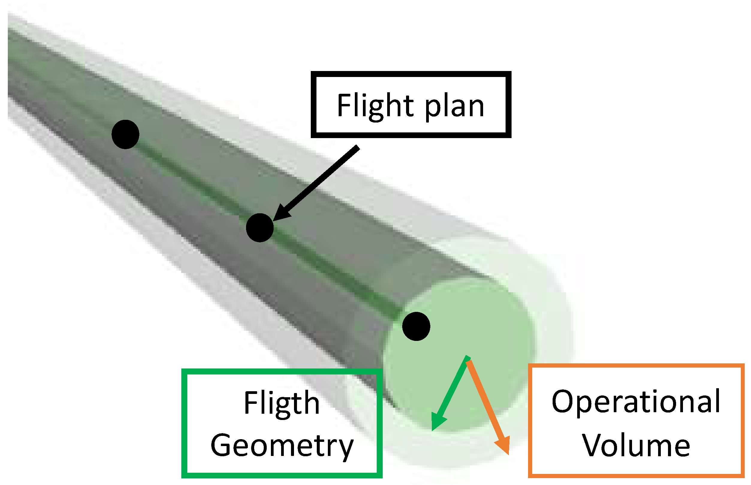
| Flight Geometry | Float | Radius of the cylindrical volume where the UAS is intended to remain during its operation |
| Operational Volume | Float | Radius of the outer cylindrical volume to account for environmental or performance uncertainties |
| U-Space Service | Functionalities | Covered in Our UTM System |
|---|---|---|
| Tracking | Cooperative UAS tracking | ✓ |
| Non-cooperative UAS tracking | ✗ | |
| Capability to exchange data with other services | ✓ | |
| Real-time tracking with data fusion from multiple sources | ✓ | |
| Tracking data recording | ✓ | |
| Monitoring | Air situation monitoring | ✓ |
| Non-cooperative UAS identification | ✗ | |
| Flight non-conformance detection | ✓ | |
| Restricted area infringement detection | ✓ | |
| Provision of traffic information for UAS operators | ✗ | |
| Conflict alerts | ✓ | |
| Emergency Management | Emergency alerts | ✓ |
| Provision of assistance information for UAS operators | ✓ | |
| Tactical Deconfliction | Transmission of deconfliction information from the USM to the UAS | ✗ |
| Transmission of deconfliction information in real time | ✓ |
| Operation 1.1 | Operation 1.2 | |
|---|---|---|
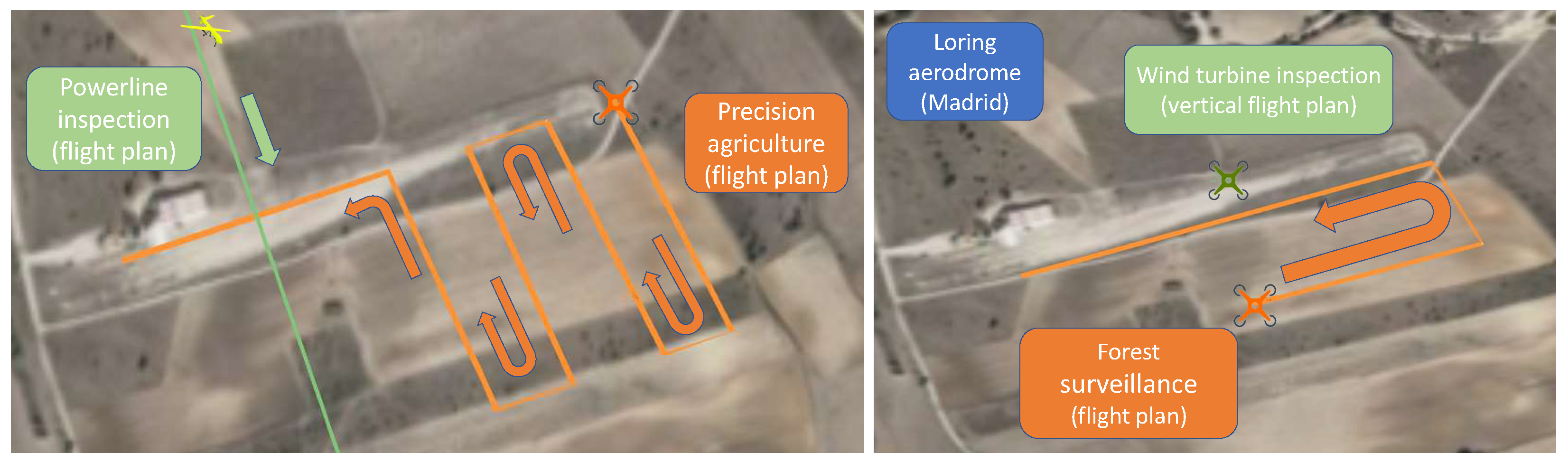
| ConOps | Precision agriculture | Powerline inspection |
| UAS type | M600 (UAS) | Atlantic I (UAS) |
| Cruising speed | 3.3 m/s | 30 m/s |
| Altitude (Above Ground Level) | 40 m | 100 m |
| Operation priority | Low | High |
| Events involved | Loss of separation | Loss of separation |
| Operation 2.1 | Operation 2.2 | |
|---|---|---|
| ConOps | Wind turbine inspection | Forest surveillance |
| UAS type | M600 (UAS) | M600 (UAS) |
| Cruising speed | 1 m/s | 1 m/s |
| Altitude (Above Ground Level) | 30–90 m | 70 m |
| Operation priority | High | High |
| Events involved | Jamming attack | Geofence conflict |
Publisher’s Note: MDPI stays neutral with regard to jurisdictional claims in published maps and institutional affiliations. |
© 2021 by the authors. Licensee MDPI, Basel, Switzerland. This article is an open access article distributed under the terms and conditions of the Creative Commons Attribution (CC BY) license (https://creativecommons.org/licenses/by/4.0/).
Share and Cite
Capitán, C.; Pérez-León, H.; Capitán, J.; Castaño, Á.; Ollero, A. Unmanned Aerial Traffic Management System Architecture for U-Space In-Flight Services. Appl. Sci. 2021, 11, 3995. https://doi.org/10.3390/app11093995
Capitán C, Pérez-León H, Capitán J, Castaño Á, Ollero A. Unmanned Aerial Traffic Management System Architecture for U-Space In-Flight Services. Applied Sciences. 2021; 11(9):3995. https://doi.org/10.3390/app11093995
Chicago/Turabian StyleCapitán, Carlos, Héctor Pérez-León, Jesús Capitán, Ángel Castaño, and Aníbal Ollero. 2021. "Unmanned Aerial Traffic Management System Architecture for U-Space In-Flight Services" Applied Sciences 11, no. 9: 3995. https://doi.org/10.3390/app11093995
APA StyleCapitán, C., Pérez-León, H., Capitán, J., Castaño, Á., & Ollero, A. (2021). Unmanned Aerial Traffic Management System Architecture for U-Space In-Flight Services. Applied Sciences, 11(9), 3995. https://doi.org/10.3390/app11093995