Article

Adaptive Sliding Mode Control for a Robotic Manipulator with Unknown Friction and Unknown Control Direction

1
Mechanical System Engineering Department, Tongyeong Campus, Gyeongsang National University, Tongyeong 53064, Korea
2
Automatic Control Department, Ho Chi Minh City University of Technology and Education, Ho Chi Minh City 700000, Vietnam
*
Author to whom correspondence should be addressed.
Appl. Sci. 2021, 11(9), 3919; https://doi.org/10.3390/app11093919
Submission received: 6 February 2021 / Revised: 22 March 2021 / Accepted: 19 April 2021 / Published: 26 April 2021

Abstract

:
This paper is aimed at addressing the tracking control issue for an n-DOF manipulator regardless of unknown friction and unknown control direction. In order to handle the above issues, an adaptive sliding mode control (ASMC) is developed with a Nussbaum function. The sliding mode control (SMC) in the proposed control guarantees the tracking problem and fast responses for the manipulator. Additionally, there are adaptive laws for the robust gain in the SMC to deal with the unknown external disturbance and reduce the chattering effect in the system. In practice, the mistakes in the connection between actuators and drivers, named unknown control direction, cause serious damage to the manipulator. To overcome this issue, the Nussbaum function is multiplied by the ASMC law. A Lyapunov approach is investigated to analyze the stability and robustness of the whole system. Finally, several simulations are implemented on a 3-DOF manipulator and their results are compared with those of the existing controllers to validate the advantages of the proposed method.

1. Introduction

For the past few decades, manipulators have been widely applied in many areas, such as drilling [1], deburring [2], and object grasping [3,4]. Due to large intrinsic nonlinearities, modeling errors, high couplings, and substantial parametric uncertainties in robot dynamics, control design for the manipulator has continued to be an exciting task for researchers. In order to obtain reasonable control performance, several robust advanced control methods have been developed, such as adaptive control, backstepping control [5,6], sliding mode control [7,8,9,10], and neural control [6,7].
Sliding mode control is well known as a robust control for nonlinear systems to deal with uncertainties [11]. The principle of SMC is based on discontinuous control to force the control system’s error state variable toward zero. Therefore, this method has been developed in many application fields [12]. However, the challenge of this method is the chattering effect which is stimulated in situations of large control gain. This phenomenon can excite high-frequency dynamics and cause instability in the controlled system [13]. In order to overcome this issue, some methods, such as boundary layer methods [13,14,15] and disturbance approximators [16,17,18], have been integrated into SMC. In [13,14,15], the sign function in SMC was swapped with the sigmoid function, saturation function, and fuzzy logic system (FLS). Since these methods operate as low-pass filters, the chattering reduction and robustness should be traded off in these situations. Disturbance approximators [16,17,18] were used to estimate the disturbance and uncertainties and indirectly decrease the magnitude of the switching gain control and chattering phenomenon. In other approaches, switching gain adaptive laws [11,19] have been applied to SMC to adjust the switching gain regarding the uncertainties and disturbances without knowledge of them. In recent years, the unknown control direction [20,21,22], which is the wrong connection in the actuator, has been interesting to many researchers. The Nussbaum gain technique is well known as a control gain estimator for handling the unknown control directions and it was first presented in 1983 by Nussbaum in Systems and Control Letters. In [23], a fault-tolerant control conducted based on feedback linearization is combined with a Nussbaum gain function and an online parameter estimator for a hypersonic vehicle. In [24], a robust adaptive and fault-tolerant control scheme was developed from a novel PID-based fault-tolerant controller with a Nussbaum-type function for a wind turbine. In [25], a command filter-based adaptive tracking controller was designed based on FLS, a command filter, and Nussbaum functions for a class of nonlinear systems with unknown control directions. In [26], Wang et al. developed an adaptive consensus tracking control based on some Nussbaum functions to manage the unknown control directions and the time-varying actuator faults simultaneously. In [27], Liu Y., etc. provided an adaptive fuzzy prescribed performance tracking control for a nonlinear switched stochastic system with unknown control directions. In this study, the adaptive controller also used a Nussbaum-type function to handle the control direction problem. From this literature, there has not been any study integrating the unknown control direction issue into the SMC design for a manipulator. Therefore, this is one of the motivations for our study.
This paper presents a novel adaptive SMC for an n-degree of freedom (DOF) robotic manipulator regardless of the existence of the unknown friction and unknown control direction. The proposed control is designed based on the SMC, adaptive switching gain laws, and Nussbaum function. The adaptive switching gain laws are investigated to regulate the robust gain of the SMC online. This approach helps in not only reducing the chattering effect but also deal with the time-varying external disturbance in the system. Moreover, a Nussbaum function is integrated into the adaptive SMC to manage the wrong control connection. Additionally, the stability and robustness of the whole system with the proposed control are analyzed by a Lyapunov theorem. Finally, some simulations are implemented on a 3-DOF manipulator and their results are compared with those of previous methods to demonstrate the superiority of the proposed control.
The rest of the paper is as follows: In Section 2, robotic dynamics and the preliminary are exhibited. In Section 3, the design procedures of the ASMC and the proposed control for the manipulator are presented and analyzed. Several simulations are presented in Section 4. Finally, several conclusions and future works are discussed in Section 5.

2. Problem Formulation and Preliminary

2.1. Manipulator Dynamics Description

The n-DOF manipulator dynamics are presented by:
M ( θ ) θ ¨ + C ( θ , θ ˙ ) θ ˙ + G ( θ ) + d ( t ) = B τ
where θ , θ ˙ , θ ¨ R n × 1 , respectively, presents angular position, angular velocity, and angular acceleration vectors of each joint, M ( θ ) R n × n is the symmetric and positive definite matrix, C ( θ , θ ˙ ) R n × n is the Coriolis and centrifugal matrix, G ( θ ) R n × 1 is the gravity vector, τ derives the torque vector, B R n × n presents the unknown control direction which is a diagonal matrix, M ˙ ( θ ) 2 C ( θ , θ ˙ ) is a skew-symmetric matrix, defined as X T [ M ˙ ( θ ) 2 C ( θ , θ ˙ ) ] X = 0 , and d(t) expresses the disturbance.
When we define x 1 = θ R n and x 2 θ ˙ R n , (1) can be rewritten as follows:
x ˙ 1 = x 2 x ˙ 2 = M 1 ( x 1 ) ( B u C ( x 1 , x 2 ) x 2 G ( x 1 ) d ( t ) )
where u = τ expresses the control input vector.
Assumption 1.
The joint trajectories x 1 d R n × n , x 2 d R n × n , and x ˙ 2 d R n × n are bounded by predefined thresholds as x 1 d < δ 1 , x 2 d < δ 2 , and x ˙ 2 d < δ 3 where δ i ( i = 1 , 2 , 3 ) are positive constants.
Assumption 2.
We suppose that the external disturbance, d ( t ) , is bounded and the inequality d ( t ) δ holds.
Control objective: Provide an advanced control for a manipulator under the presence of unknown friction and unknown control direction to not only guarantee the tracking requirements but also reduce the chattering effect in the control signal.

2.2. Nussbaum Function

A function N ( ζ ) can be called a Nussbaum-like function if it satisfies the following properties [28]:
lim s sup s 0 s N ( ζ ) d ζ = +
lim s inf s 0 s N ( ζ ) d ζ =
In this study, the Nussbaum function N ( ζ ) = e ζ 2 cos ( π 2 ζ ) is considered.
Lemma 1
([29,30]). Let V ( t ) and ζ i ( t ) be smooth functions defined on [ 0 , t f ) with V ( t ) > 0 , for any t [ 0 , t f ) , if the following inequality is satisfied:
V ( t ) < c 0 ± 0 t i = 1 n ( g i N ( ζ i ) ± 1 ) ζ ˙ i d τ
where g i is a non-zero constant and c 0 expresses some suitable constant, then V ( t ) ζ i ( t ) and 0 t i = 1 n ( g i N ( ζ i ) ± 1 ) ζ ˙ i d τ must be bounded on [ 0 , t f ) .

3. Control Design

3.1. Adaptive Sliding Mode Control

Remark 1.
This section presents an ASMC for the robotic manipulator under the existence of disturbance. The unknown control direction does not happen in this case. Therefore, B = I n × n .
e = x 1 x 1 d is the trajectory tracking error and x i d presents the desired trajectory. A sliding mode surface is selected as follows:
s = e ˙ + λ e
where λ = d i a g ( λ 1 , λ 2 , , λ n ) R n × n , ( i = 1 , 2 ) are positive definite matrices.
The time derivative of the sliding surface is computed as
s ˙ = e ¨ + λ e ˙
Replacing (2) into (7), it is rewritten as follows:
s ˙ = λ e ˙ + M 1 ( x 1 ) ( B u C ( x 1 , x 2 ) x 2 G ( x 1 ) d ( t ) ) x ¨ 1 d
Based on assumption 2 and the sliding mode design procedure, an SMC can be designed as
u = u e q + u r
where
u e q = B 1 ( M ( x 1 ) ( x ¨ 1 d λ e ˙ ) + C ( x 1 , x 2 ) ( x ˙ 1 d λ e ) + G ( x 1 ) k s )
is an equivalent control with k = d i a g ( [ k 1 , , k n ] ) R n × n , and
u r = B 1 η s i g n ( s )
is used to ensure the stability of the system with the existence of the uncertainties, η = d i a g ( [ η 1 , , η n ] ) R n × n expresses a diagonal positive matrix which is chosen for the condition η i | δ i | . The function is s i g n ( x ) = [ s i g n ( x 1 ) , , s i g n ( x n ) ] T R n × 1 . In practice, the external disturbance usually changes with respect to time, and the robust gains can cause the chattering effect when the robust gains are significantly larger than the external disturbance. In order to overcome this disadvantage, fast adaptive laws are developed to adjust the robust gain online with respect to the external disturbance. The robust control (11) is replaced by the equation below:
u r = B 1 η ^ s i g n ( s )
The adaptive laws are selected as follows:
η ^ ˙ i = { κ 1 i ( κ 2 i 1 | s i | ) γ ( t ) γ ( t ) , if   0 < η ^ i , min i   | s i | ε 2 κ 1 i κ 2 i | s i | 1 if   η ^ = 0 ,   min i   | s i | ε 2 0 o t h e r w i s e
where γ ( t ) = s i g n ( | s i | ε 1 ) , κ j i ( j = 1 , 2 ; i = 1 , , n ) are positive constants, ε 1 are predefined error boundaries, ε 1 = 10 ε 2 0 .
These adaptive robust gain laws do not need knowledge of the upper boundary of the external disturbance. The adaptive robust gains will rapidly grow and drive the sliding surface s i ( i = 1 , , n ) to the desired areas that are smaller than ε 1 i . Otherwise, when the sliding variable stays in these regions, the gains will gradually reduce. From the property of the adaptive robust gain laws, the chattering effect is significantly reduced under the existence of the time-varying external disturbance.
Theorem 1.
When we consider the external disturbance in the robot manipulator with the known control direction described in (2), the sliding mode surface presented in (6), and the controller defined in (9), then the sliding variables, s i , are bounded. Additionally, the chattering effect is reduced significantly.
Proof. 
The Lyapunov function is selected as follows:
V 1 = 1 2 s T M ( x 1 ) s + 1 2 η ˜ T κ 1 1 κ 2 η ˜
where η ˜ i = η i * η ^ i , ( i = 1 , , n ) are robust gain errors.
Assumption 3.
The robust gain error term (14) is bounded. The condition 1 2 η ˜ T κ 1 1 κ 2 η ˜ ζ η holds.
Taking the derivative of the Lyapunov function, V 1 , with respect to time, we have
V ˙ 1 = s T M ( x 1 ) s ˙ + 1 2 s T M ˙ ( x 1 ) s + η ˜ T κ 1 1 κ 2 η ˜ ˙ = s T M ( x 1 ) ( λ e ˙ + M 1 ( x 1 ) ( B u C ( x 1 , x 2 ) x 2 G ( x 1 ) d 1 ( t ) ) x ¨ d ) ) + 1 2 s T M ˙ ( x 1 ) s + η ˜ T κ 1 1 κ 2 η ˜ ˙
By applying the control laws (9) and skew-matrix property in (15), the result is presented as follows:
V ˙ 1 = s T ( k s η ^ s i g n ( s ) d ( t ) ) + η ˜ T κ 1 1 κ 2 η ˜ ˙ s T k s i = 1 n ( η ^ i | d i ( t ) | ) | s i | i = 1 n η ˜ i κ 1 i 1 κ 2 i η ^ ˙ i i = 1 n ( k i s i 2 η ˜ i ( | s i | κ 1 i 1 κ 2 i η ^ ˙ i ) )
Now, we take into account two adaptive cases: s ε 1 and s < ε 1 . In the first case, s ε 1 , the differential Lyapunov function is presented as follows:
V ˙ 1 = i = 1 n k i s i 2 i = 1 n k i ε 1 2
This result shows that V 1 is decreasing and bounded since 0 V 1 ( t ) V 1 ( 0 ) . It means that the sliding variable s i reaches the small region of the sliding surface, i.e., | s i | ε 1 .
In the other cases, s ε 1 , it means that all sliding variables s i approach the regions | s i | ε 1 , and they may move in or leave the regions because V ˙ 1 is not guaranteed to be semi-negative in the vicinity of the sliding manifold. If any sliding variable s i moves out of the region | s i | ε 1 , then V ˙ 1 will become negative again. This result will force the variable to go back toward the sliding surfaces.
When all the sliding variables, s i , stay in the region | s i | ε 1 , the upper bound of the sliding variable is computed as follows:
1 2 s T M ( x 1 ) s V 1 1 2 s T M ( x 1 ) s + 1 2 η ˜ κ 1 1 κ 2 η ˜
Since 1 2 η ˜ κ 1 1 κ 2 η ˜ in (18) is bounded, we have
V 1 < 1 2 λ m ax ( M ( x 1 ) ) n ε 2 + 1 2 ζ η
Based on (18) and (19), we obtain
1 2 λ min ( M ( x 1 ) ) i = 1 n s i 2 < 1 2 λ m ax ( M ( x 1 ) ) n ε 1 2 + 1 2 ζ η i = 1 n s i 2 < λ m ax ( M ( x 1 ) ) λ min ( M ( x 1 ) ) n ε 1 2 + ζ η λ min ( M ( x 1 ) )
This means that
i = 1 n s i 2 < λ m ax ( M ( x 1 ) ) λ min ( M ( x 1 ) ) n ε 1 2 + ζ η λ min ( M ( x 1 ) )
Equation (21) means that sliding variables, s i , are ultimately uniform bounded. The upper boundary in (21) can be adjusted by the parameters κ 1 , κ 2 , ε 1 . □

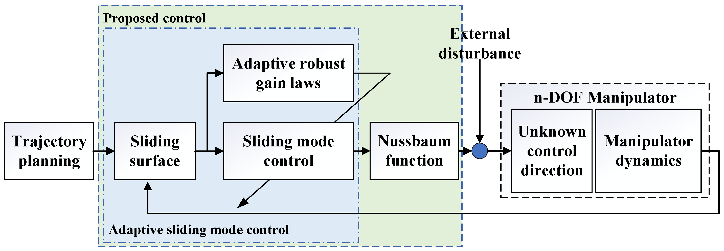
3.2. Proposed Control

The schematic of the proposed control presented in Figure 1 is developed from the adaptive SMC. Therefore, the proposed control can deal with the external disturbance and chattering effect. Moreover, a Nussbaum function is added in the adaptive SMC to overcome the unknown control direction in the robot system.
Remark 2.
The proposed control is developed to overcome the unknown control direction which means that the signal of the control input gains can be nonpositive.
The proposed control is chosen as follows:
u ( t ) = N ( ζ ) u 0 R n × 1
where u 0 = ( M ( x 1 ) ( x ¨ d λ e ˙ ) + C ( x 1 , x 2 ) ( x ˙ d λ e ) + G ( x 1 ) k s η ^ s i g n ( s ) ) R n × 1
N ( ζ ) = d i a g ( [ N ( ζ 1 ) N ( ζ n ) ] ) R n × n ,   N ( ζ i ) = e ζ i 2 cos ( π 2 ζ i ) . ζ ˙ i = s i u 0 i , ( i = 1 , , n )
Theorem 2.
When we consider the external disturbance in the robot manipulator with unknown control direction described in (2), the SM surface presented in (6), the controller defined in (22), and the adaptive robust gain laws provided in (13), then the sliding variables, s i , are bounded and the unknown control direction is overcome. Consequently, the closed-loop system is proven to be semi-globally uniformly ultimately bounded (SGUUB).
Proof of Stability.
The stability of the whole system is proven by using the Lyapunov function (14), and the analysis is implemented as follows:
The time derivative of the Lyapunov function (14) is presented as follows:
V ˙ 1 = s T M ( x 1 ) s ˙ + 1 2 s T M ˙ ( x 1 ) s + η ˜ T κ 1 1 κ 2 η ˜ ˙ = s T ( M ( x 1 ) ( λ e ˙ x ¨ d ) + B u C ( x 1 , x 2 ) ( x ˙ d λ e ) G ( x 1 ) d 1 ( t ) ) + η ˜ T κ 1 1 κ 2 η ˜ ˙
By replacing the proposed control (22) into (24), the result is yielded as follows:
V ˙ 1 = s T M ( x 1 ) s ˙ + 1 2 s T M ˙ ( x 1 ) s + η ˜ T κ 1 1 κ 2 η ˜ ˙ = s T ( M ( x 1 ) ( λ e ˙ x ¨ d ) C ( x 1 , x 2 ) ( λ e x ˙ d ) G ( x 1 ) d 1 ( t ) + B N ( ζ ) ( ( M ( x 1 ) ( x ¨ d λ e ˙ ) + C ( x 1 , x 2 ) ( x ˙ d λ e ) + G ( x 1 ) k s η ^ s i g n ( s ) ) ) + η ˜ T κ 1 1 κ 2 η ˜ ˙ = s T ( M ( x 1 ) ( λ e ˙ x ¨ d ) C ( x 1 , x 2 ) ( x ˙ d λ e ) G ( x 1 ) + k s + η ^ s i g n ( s ) k s η ^ s i g n ( s ) d 1 ( t ) + B N ( ζ ) ( ( M ( x 1 ) ( x ¨ d λ e ˙ ) + C ( x 1 , x 2 ) ( x ˙ d λ e ) + G ( x 1 ) k s η ^ s i g n ( s ) ) ) + η ˜ T κ 1 1 κ 2 η ˜ ˙ = s T k s s T ( η ˜ s i g n ( s ) + ε ) ( 1 B N ( ζ ) ) ζ ˙ + η ˜ T κ 1 1 κ 2 η ˜ ˙ c V ( 1 B N ( ζ ) ) ζ ˙ + δ
By multiplying two sides of (25) with e c t and integrating over [ 0 , t f ] , the result is presented as follows:
0 V ( t ) δ c + ( V ( 0 ) δ c ) e c t e c t 0 t f ( 1 B N ( ζ ) ) ζ ˙ e c τ d τ
From Lemma 1 and (26), we conclude that V ( t ) , ζ i , and 0 t f ( 1 B N ( ζ ) ) ζ ˙ e c τ d τ are bounded and semi-globally uniformly ultimately bounded (SGUUB). □

4. Numerical Simulations

4.1. Simulation Descriptions

In this section, two simulations on a 3-DOF manipulator are implemented to show the efficiencies of the proposed method. In the first simulation, the controllers are applied on the manipulator under the presence of the friction model and known control direction. In the second simulation, besides the friction model, the unknown control direction is taken into account in the manipulator dynamics. The simulation environment is MATLAB 2020a with a sampling time of 10 3 s. The 3-DOF manipulator dynamics are mentioned in [5]. Their parameters are presented in Table 1.
The friction model in the manipulator dynamics consists of the viscous and Coulomb frictions, presented as follows:
d ( t ) = b x 2 ( t ) + c s i g n ( x 2 ( t ) )
where b = 0.05 I 3 × 3 ( Nms / rad ) and c = 0.05 I 3 × 3 .
The trajectory reference in the Cartesian coordination is presented as x d = 0.4 + 0.15 cos ( 0.2 π ) ( m ) , y d = 0 ( m ) , z d = 0.15 cos ( 0.2 π + π / 2 ) ( m ) , and the rotary angle around the z-axis is zero.

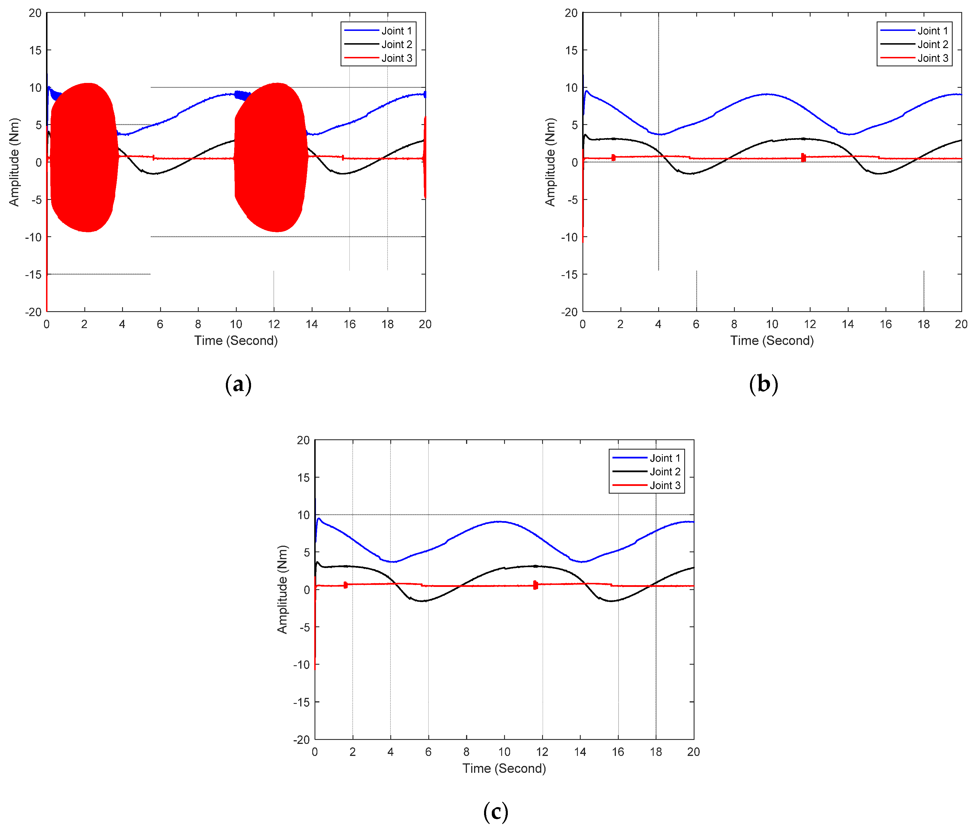
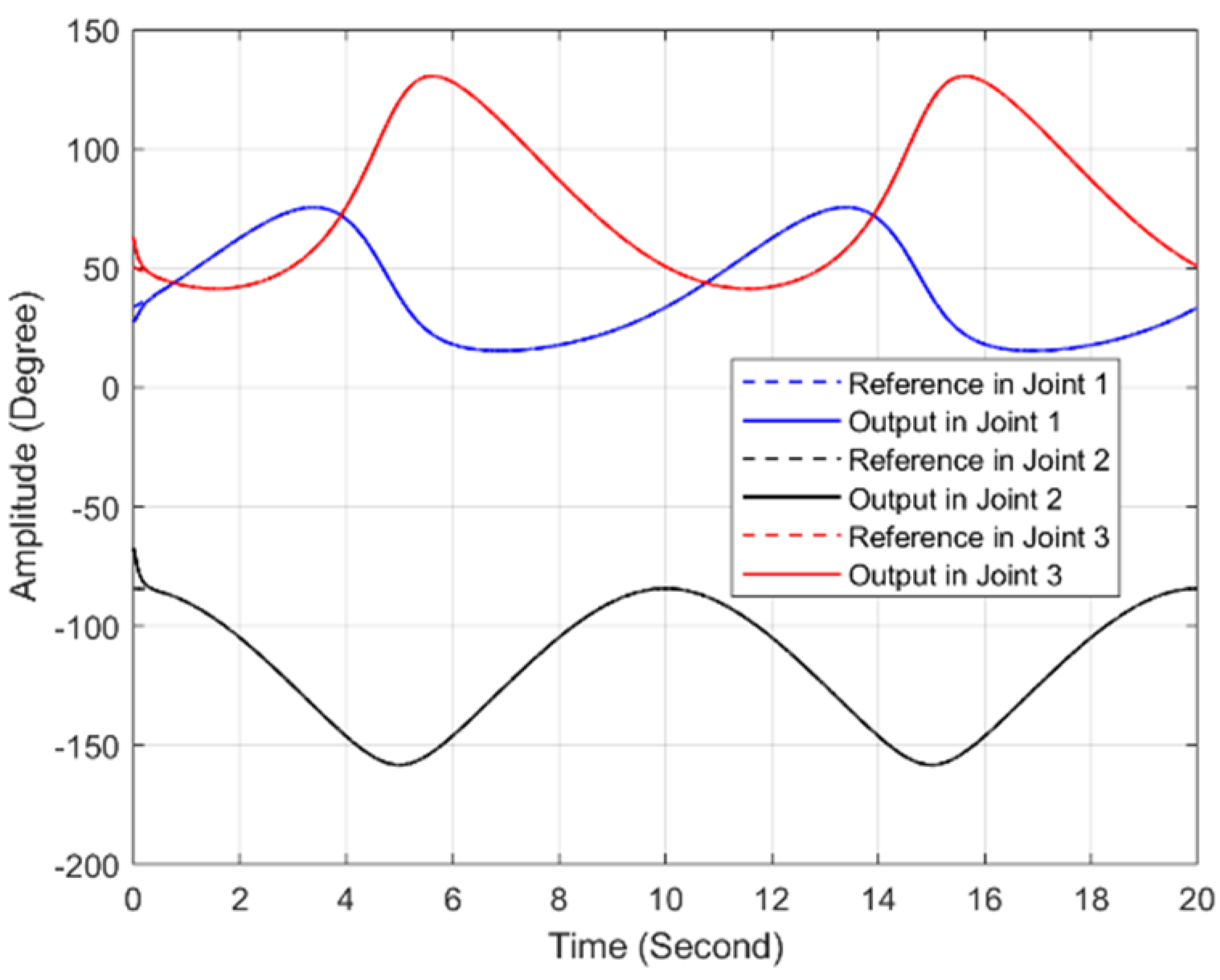
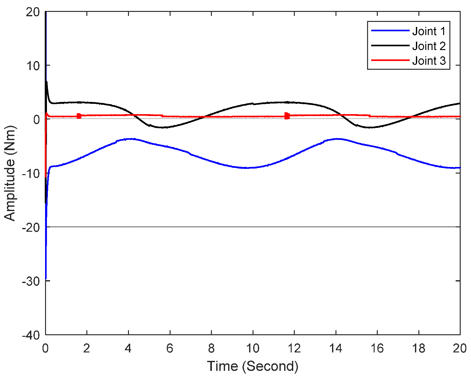
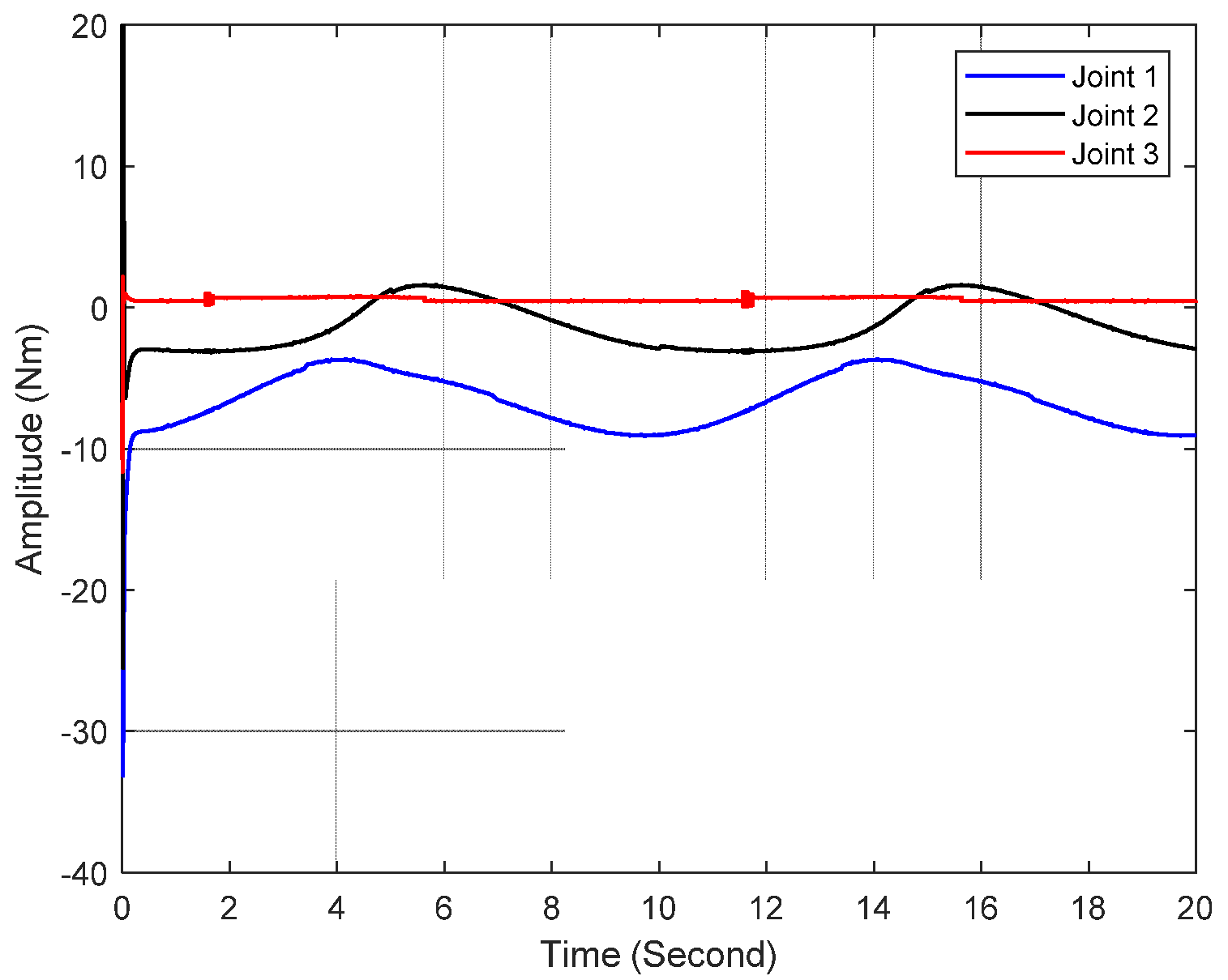
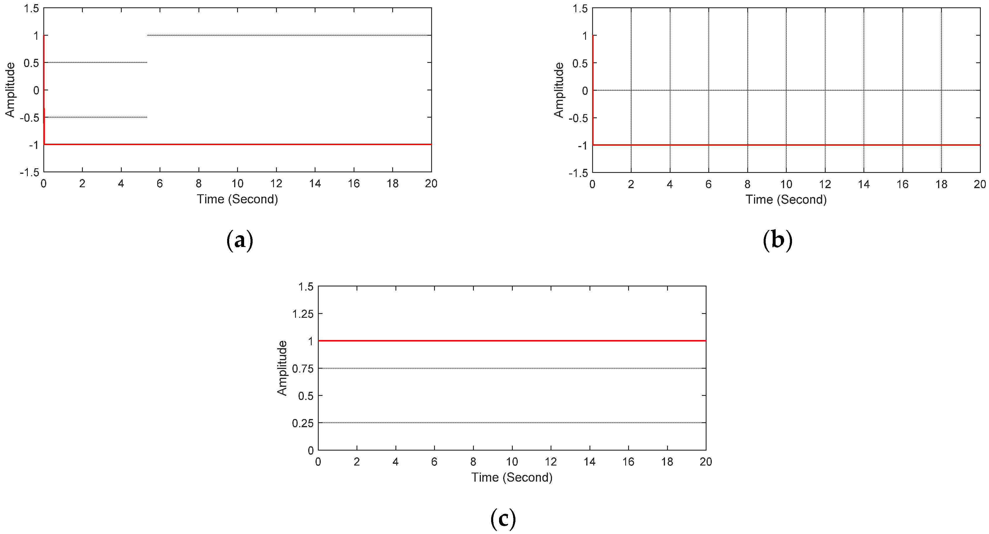
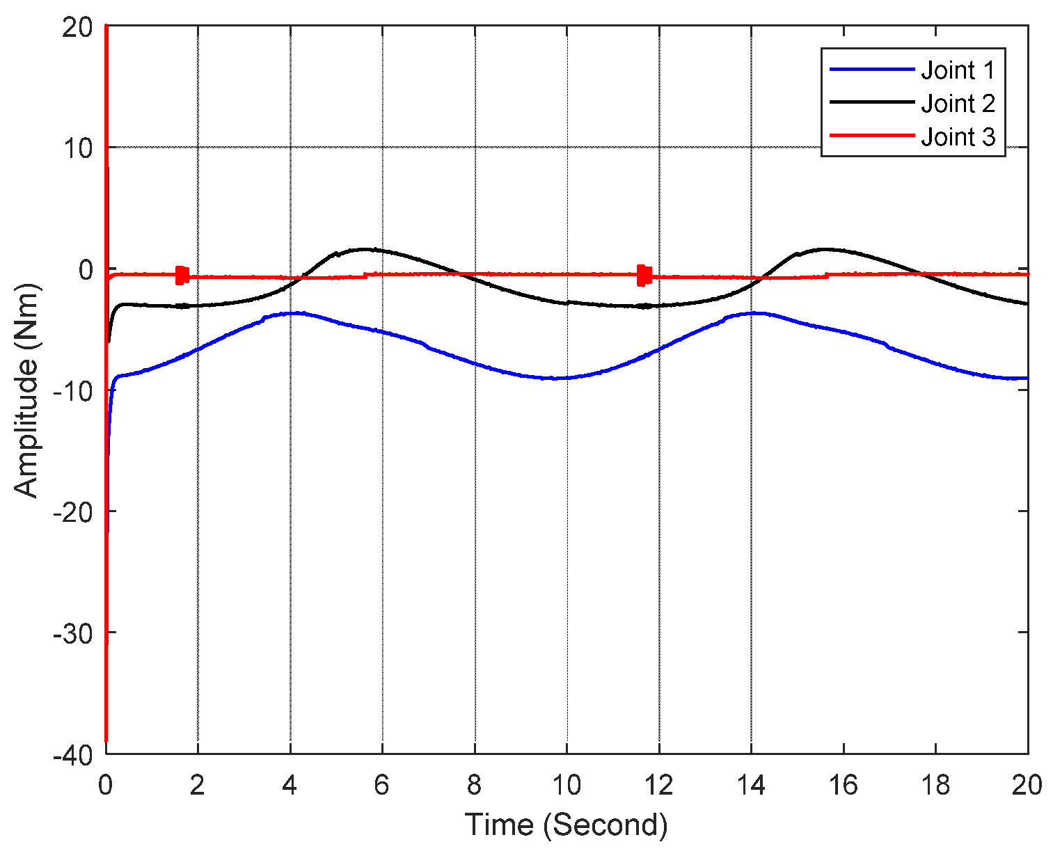
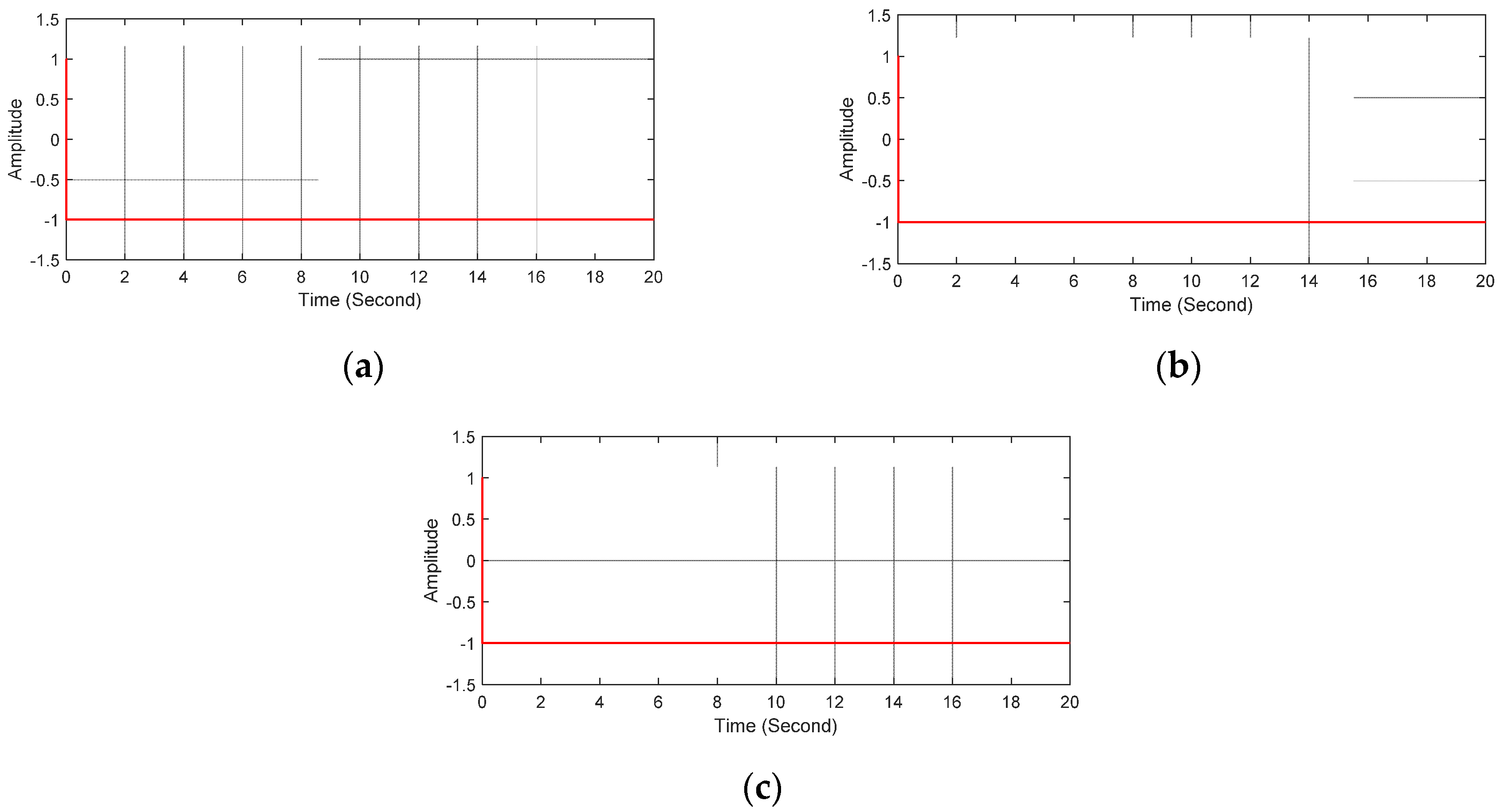
4.2. Simulation Comparisons

In order to demonstrate the advantages of the proposed control, the results of the proposed control are compared with those of the sliding mode control (SMC) and adaptive SMC (ASMC). The SMC is presented in (6), (9), (10) and (11). The ASMC is computed by (6), (9), (10), (12) and (13).
Remark 1.
The parameters of the three controllers are presented in Table 2. As the SMC is designed based on the manipulator dynamics, the ASMC is developed from the SMC and the proposed control inherits from the ASMC, so the parameters of the ASMC inherit from the SMC and the parameters of the proposed control inherit from the ASMC to maintain the fairness in comparisons.
Remark 2.
The data are multiplied with a constant to convert from radian units to degree units before they are plotted in the figures of Section 4.3.
Remark 3.
In order to improve the ability of the Nussbaum functions in control direction detection, the Nussbaum function in the simulation is modified as follows:
N ( ζ i ) = s i g n ( e ζ i 2 cos ( π 2 ζ i ) )

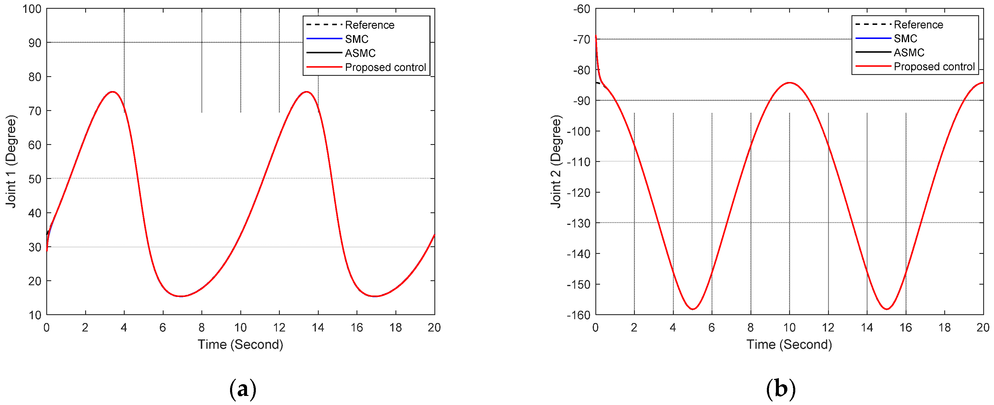
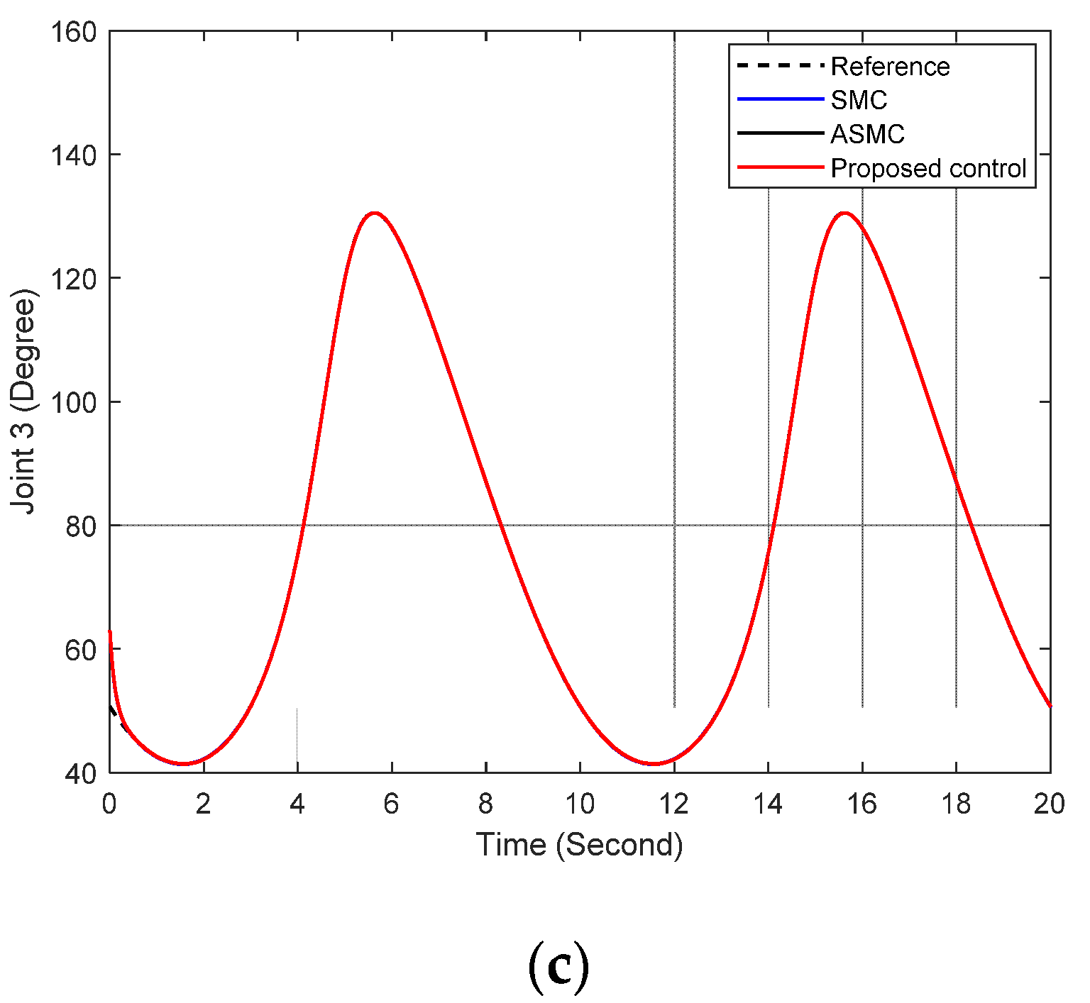
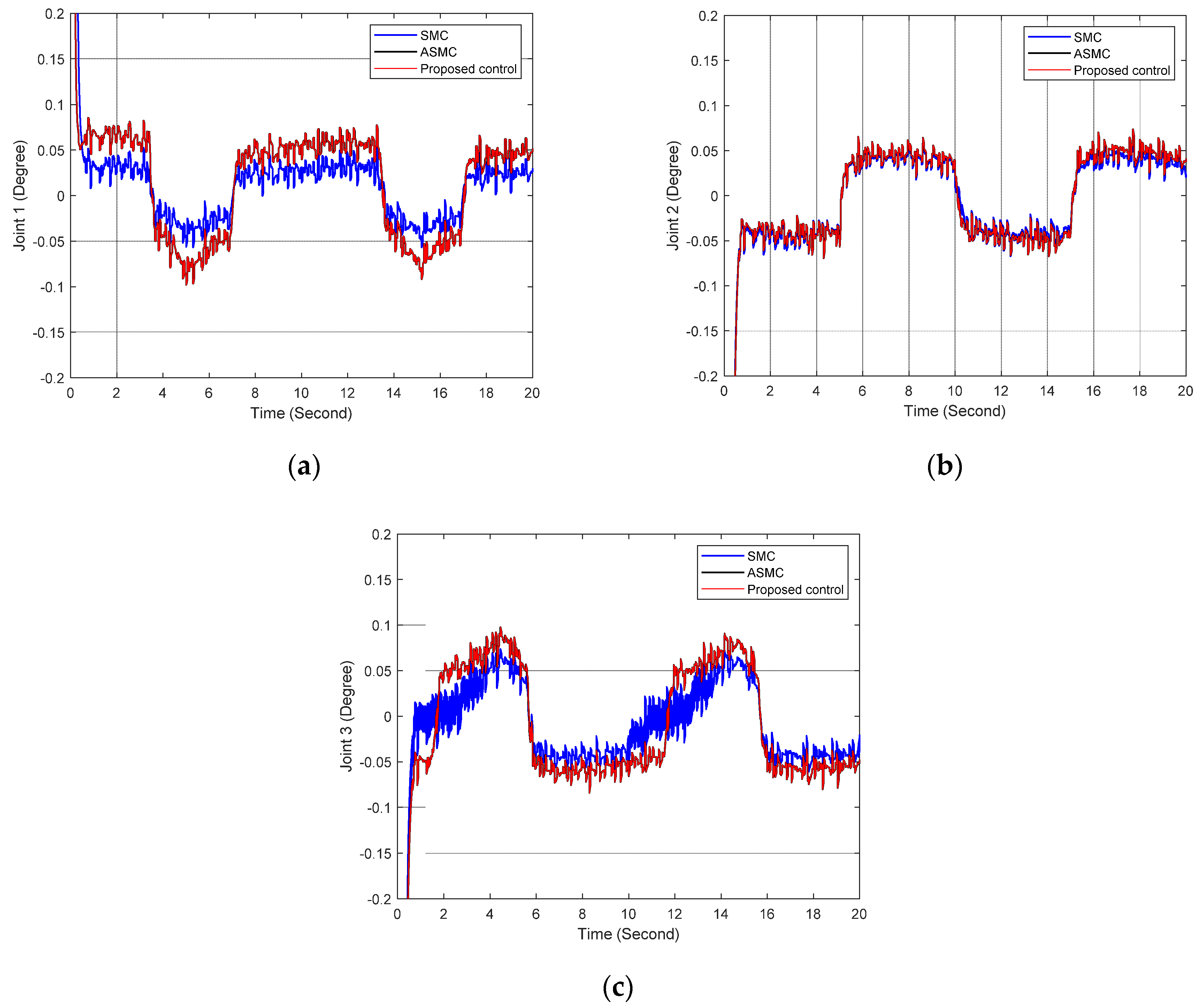
4.3. Simulation Results

In the first simulation case, the results in Figure 2 show the output performances at three joints of the SMC (blue line), the ASMC (black line), and the proposed control (red line), tracked to the reference signals. Figure 3 presents the error responses of the SMC with a blue line, the ASMC with a black line, and the proposed control with a red line. Figure 4 presents the control signal performance of SMC in Figure 4a, ASMC in Figure 4b, and proposed control in Figure 4c. These results show the effectiveness of the adaptive laws for robust gain in chattering suppression in the ASMC and the proposed controller.
In the second case, three wrong connection situations are implemented to prove the superiority of the proposed control. These situations are the wrong connection in an actuator, B = d i a g ( [ 1 1 1 ] T ) , two actuators B = d i a g ( [ 1 1 1 ] T ) , and all three actuators B = d i a g ( [ 1 1 1 ] T ) . Figure 5 shows the output responses of the 3-DOF manipulator with the proposed control with the wrong connection in actuator 1. These results show good tracking performances. Figure 6 presents the control signals of the proposed control at each joint of the manipulator. Comparing to Figure 4c, the control signal of joint 1 in Figure 6 has a different direction, which exhibits the wrong connection in actuator 1. Figure 7 plots the Nussbaum function at each joint to help the controlled system overcome the unknown control direction. The response of the Nussbaum function in Figure 7a changed from +1 to −1 to compensate for the connection issue in actuator 1.
Next, the advantages of the proposed control are taken into account with the wrong connections in actuators 1 and 2, B = d i a g ( [ 1 1 1 ] T ) . Figure 8 is the control responses of the proposed controller. The results show that the control signals in actuator 1 and 2 are different directions when compared to the control signals in actuator 1 and 2 with the normal case in Figure 4c. The effectiveness is shown in Figure 9, which presents Nussbaum function responses at each joint with the wrong connection in actuator 1 and 2. The results in Figure 9a,b turn from +1 into −1 to overcome the wrong connections.
In the final subcase, the wrong connection at all three actuators, B = d i a g ( [ 1 1 1 ] T ) , is considered. Figure 10 presents the control signals of the proposed controllers. The sign of the control responses of the proposed control in three actuators is different compared to the control responses in the normal case, as shown in Figure 4c. Additionally, Figure 11 shows the Nussbaum function responses which turn into −1 to help the proposed control to deal with the unknown control direction.

5. Conclusions

This paper was aimed at addressing the tracking control issue for an n-DOF manipulator with the existence of unknown friction and unknown control direction. To overcome these issues, an adaptive sliding mode control (ASMC) is developed with a Nussbaum function. The SMC in the proposed control ensures the tracking problem and fast responses for the manipulator. Additionally, there are adaptive laws for the robust gain in the SMC to deal with the unknown friction and suppress the chattering effect in the system. In practice, the mistakes in the connection between actuators and drivers, named unknown control direction, cause serious damage to the manipulator. To manage this issue, the Nussbaum function is multiplied by the ASMC law. A Lyapunov approach is investigated to analyze the stability and robustness of the whole system in theory. Finally, several simulations are implemented on a 3-DOF manipulator and their results are compared with those of the existing controllers to prove the advantages of the proposed method.
For future works, some experiments will be carried out to demonstrate the advantages of the proposed methods. The results in the paper can be used to conduct advanced fault-tolerant controllers for robotic manipulators.

Author Contributions

Conceptualization, S.-H.H. and D.-T.T.; Data curation, M.S.T.; Formal analysis, S.-H.H. and M.S.T.; Investigation, S.-H.H.; Methodology, S.-H.H. and D.-T.T.; Resources, S.-H.H. and D.-T.T.; Software, S.-H.H. and M.S.T.; Supervision, D.-T.T.; Validation, S.-H.H., M.S.T. and D.-T.T.; Visualization, S.-H.H. and M.S.T.; Writing—original draft, S.-H.H. and D.-T.T.; Writing—review & editing, D.-T.T. All authors have read and agreed to the published version of the manuscript.

Funding

This research received no external funding.

Conflicts of Interest

The authors declare no conflict of interest.

References

  1. Zanchettin, A.M.; Rocco, P.; Robertsson, A.; Johansson, R. Exploiting task redundancy in industrial manipulators during drilling operations. Proc. IEEE Int. Conf. Robot. Autom. 2011, 128–133. [Google Scholar] [CrossRef]
  2. Kazerooni, H.; Bausch, J.J.; Kramer, B.M. An Approach to Automated Deburring by Robot Manipulators. J. Dyn. Syst. Meas. Control. 1986, 108, 354–359. [Google Scholar] [CrossRef]
  3. Li, G.; Huang, H.; Guo, H.; Li, B. Dynamic Modeling and Control for a Deployable Grasping Manipulator. IEEE Access 2019, 7, 23000–23011. [Google Scholar] [CrossRef]
  4. Li, Z.; Zhao, T.; Chen, F.; Hu, Y.; Su, C.Y.; Fukuda, T. Reinforcement Learning of Manipulation and Grasping Using Dynamical Movement Primitives for a Humanoidlike Mobile Manipulator. IEEE/ASME Trans. Mechatron. 2018, 23, 121–131. [Google Scholar] [CrossRef]
  5. Tran, D.T.; Dao, H.V.; Dinh, T.Q.; Ahn, K.K. Output feedback control via linear extended state observer for an uncertain manipulator with output constraints and input dead-zone. Electronics 2020, 9, 1355. [Google Scholar] [CrossRef]
  6. Tran, D.-T.; Truong, H.-V.-A.; Ahn, K.K. Adaptive backstepping sliding mode control based RBFNN for a hydraulic manipulator including actuator dynamics. Appl. Sci. 2019, 9, 1265. [Google Scholar] [CrossRef] [Green Version]
  7. Yen, V.T.; Nan, W.Y.; van Cuong, P. Robust Adaptive Sliding Mode Neural Networks Control for Industrial Robot Manipulators. Int. J. Control. Autom. Syst. 2019, 17, 783–792. [Google Scholar] [CrossRef]
  8. Van, M.; Mavrovouniotis, M.; Ge, S.S. An adaptive backstepping nonsingular fast terminal sliding mode control for robust fault-tolerant control of robot manipulators. IEEE Trans. Syst. Man, Cybern. Syst. 2019, 49, 1448–1458. [Google Scholar] [CrossRef] [Green Version]
  9. Le, Q.D.; Kang, H.-J. Finite-Time Fault-Tolerant Control for a Robot Manipulator Based on Synchronous Terminal Sliding Mode Control. Appl. Sci. 2020, 10, 2998. Available online: https://www.mdpi.com/2076-3417/10/9/2998 (accessed on 25 April 2020). [CrossRef]
  10. Lee, J.; Chang, P.H.; Jin, M. Adaptive Integral Sliding Mode Control With Time-Delay Estimation for Robot Manipulators. IEEE Trans. Ind. Electron. 2017, 64, 6796–6804. [Google Scholar] [CrossRef]
  11. Tran, D.T.; Ba, D.X.; Ahn, K.K. Adaptive Backstepping Sliding Mode Control for Equilibrium Position Tracking of an Electrohydraulic Elastic Manipulator. IEEE Trans. Ind. Electron. 2020, 67, 3860–3869. [Google Scholar] [CrossRef]
  12. Utkin, V.; Guldner, J.; Shi, J. Sliding Mode Control in Electro-Mechanical Systems; CRC Press: Boca Ration, FL, USA, 2009. [Google Scholar]
  13. Perruquetti, W.; Barbot, J.-P. Sliding Mode Control in Engineering; CRC Press: Boca Ration, FL, USA, 2002. [Google Scholar]
  14. Roopaei, M.; Jahromi, M.Z. Chattering-free fuzzy sliding mode control in MIMO uncertain systems. Nonlinear Anal. Theory Methods Appl. 2009, 71, 4430–4437. [Google Scholar] [CrossRef]
  15. Amer, A.F.; Sallam, E.A.; Elawady, W.M. Adaptive fuzzy sliding mode control using supervisory fuzzy control for 3 DOF planar robot manipulators. Appl. Soft Comput. J. 2011, 11, 4943–4953. [Google Scholar] [CrossRef]
  16. Jung, S. Improvement of Tracking Control of a Sliding Mode Controller for Robot Manipulators by a Neural Network. Int. J. Control. Autom. Syst. 2018, 16, 937–943. [Google Scholar] [CrossRef]
  17. Zhao, L.; Li, Q.; Liu, B.; Cheng, H. Trajectory Tracking Control of a One Degree of Freedom Manipulator Based on a Switched Sliding Mode Controller with a Novel Extended State Observer Framework. IEEE Trans. Syst. Man Cybern. Syst. 2019, 49, 1110–1118. [Google Scholar] [CrossRef]
  18. Wang, Y.; Jiang, S.; Yan, F.; Chen, B. Sliding Mode Control of A Newly Designed Cable-Driven Manipulator with Time Delay Estimation. In Proceedings of the 17th International Conference on Control, Automation and Systems (ICCAS), Jeju, Korea, 18–21 October 2017; No. 51705243. pp. 1605–1609. [Google Scholar]
  19. Roy, S.; Kar, I.N. Adaptive sliding mode control of a class of nonlinear systems with artificial delay. J. Franklin Inst. 2017, 354, 8156–8179. [Google Scholar] [CrossRef]
  20. Yu, J.; Shi, P.; Lin, C.; Yu, H. Adaptive Neural Command Filtering Control for Nonlinear MIMO Systems with Saturation Input and Unknown Control Direction. IEEE Trans. Cybern. 2020, 50, 2536–2545. [Google Scholar] [CrossRef] [PubMed]
  21. Zhai, D.; An, L.; Li, X.; Zhang, Q. Adaptive fault-tolerant control for nonlinear systems with multiple sensor faults and unknown control directions. IEEE Trans. Neural Netw. Learn. Syst. 2018, 29, 4436–4446. [Google Scholar] [CrossRef]
  22. Wang, H.; Karimi, H.R.; Liu, P.X.; Yang, H. Adaptive neural control of nonlinear systems with unknown control directions and input dead-zone. IEEE Trans. Syst. Man Cybern. Syst. 2018, 48, 1897–1907. [Google Scholar] [CrossRef]
  23. Xu, B.; Qi, R.; Jiang, B. Adaptive Fault-Tolerant Control for HSV with Unknown Control Direction. IEEE Trans. Aerosp. Electron. Syst. 2019. [Google Scholar] [CrossRef]
  24. Habibi, H.; Nohooji, H.R.; Howard, I. Adaptive PID control of wind turbines for power regulation with unknown control direction and actuator faults. IEEE Access 2018, 6, 37464–37479. [Google Scholar] [CrossRef]
  25. Xia, J.; Zhang, J.; Feng, J.; Wang, Z.; Zhuang, G. Command Filter-Based Adaptive Fuzzy Control for Nonlinear Systems With Unknown Control Directions. IEEE Trans. Syst. Man Cybern. Syst. 2019, 1–9. [Google Scholar] [CrossRef]
  26. Wang, C.; Wen, C.; Guo, L. Adaptive Consensus Control for Nonlinear Multi-Agent Systems With Unknown Control Directions and Time-Varying Actuator Faults. IEEE Trans. Autom. Control. 2020, 1. [Google Scholar] [CrossRef]
  27. Liu, Y.; Ma, H. Adaptive Fuzzy Tracking Control of Nonlinear Switched Stochastic Systems With Prescribed Performance and Unknown Control Directions. IEEE Trans. Syst. Man Cybern. Syst. 2020, 50, 590–599. [Google Scholar] [CrossRef]
  28. Ge, S.S.; Wang, J. Robust adaptive neural control for a class of perturbed strict feedback nonlinear systems. IEEE Trans. Neural Netw. 2002, 13, 1409–1419. [Google Scholar] [CrossRef]
  29. Boulkroune, A.; Tadjine, M.; M’Saad, M.; Farza, M. Fuzzy adaptive controller for MIMO nonlinear systems with known and unknown control direction. Fuzzy Sets Syst. 2010, 161, 797–820. [Google Scholar] [CrossRef] [Green Version]
  30. Ramezani, Z.; Arefi, M.M.; Zargarzadeh, H.; Jahed-Motlagh, M.R. Neuro observer-based control of pure feedback MIMO systems with unknown control direction. IET Control Theory Appl. 2017, 11, 213–224. [Google Scholar] [CrossRef]
Figure 1. Schematic of the proposed control.
Applsci 11 03919 g001
Figure 2. Output responses of the SMC, ASMC, and proposed control in (a) link 1, (b) link 2, (c) link 3.
Applsci 11 03919 g002aApplsci 11 03919 g002b
Figure 3. Error efforts with the SMC, ASMC, and proposed control in (a) link 1, (b) link 2, (c) link 3.
Applsci 11 03919 g003
Figure 4. Control performance of (a) SMC, (b) ASMC, and (c) proposed controller in the 3-DOF manipulator.
Applsci 11 03919 g004
Figure 5. The output responses of the proposed control under the presence of the wrong connection in actuator 1, B = d i a g ( [ 1 1 1 ] T ) .
Applsci 11 03919 g005
Figure 6. Control responses of the proposed controller with the wrong connection in actuator 1, B = d i a g ( [ 1 1 1 ] T ) .
Applsci 11 03919 g006
Figure 7. Nussbaum function performance of the proposed control in (a) joint 1, (b) joint 2, and (c) joint 3.
Applsci 11 03919 g007
Figure 8. Control responses of the proposed controller with the wrong connection in actuator 1 and actuator 2, B = d i a g ( [ 1 1 1 ] T ) .
Applsci 11 03919 g008
Figure 9. Nussbaum function performance of the proposed control in (a) joint 1, (b) joint 2, and (c) joint 3, B = d i a g ( [ 1 1 1 ] T ) .
Applsci 11 03919 g009
Figure 10. Control responses of the proposed controller with the wrong connection in all three actuators, B = d i a g ( [ 1 1 1 ] T ) .
Applsci 11 03919 g010
Figure 11. Nussbaum function performance of the 3-DOF manipulator with the proposed control in (a) joint 1, (b) joint 2, and (c) joint 3, B = d i a g ( [ 1 1 1 ] T ) .
Applsci 11 03919 g011
Table 1. Parameters of the 3-DOF robotic manipulator.
Variable DescriptionVariable Description
l 1 = 0.46   m Length of the 1st link m 1 = 0.7   kg Mass of the 1st link
l 2 = 0.4   m Length of the 2nd link m 2 = 0.6   kg Mass of the 2nd link
l 3 = 0.2   m Length of the 3rd link m 3 = 0.3   kg Mass of the 3rd link
g = 9.81   ms 2 Gravity constant
Table 2. Coefficients of the SMC, ASMC, and the proposed control.
ControllersParameters
SMC λ = 10 I 3 × 3 , k = 3 I 3 × 3 , η = 15 d i a g ( [ 2 1 1 ] T )
ASMC λ = 10 I 3 × 3 , k = 3 I 3 × 3 , ε 1 = 0.001 , κ 1 = 10 2 [ 2.5 2.5 1 ] , κ 2 = 5 · 10 4 [ 1 1 1 ]
Proposed control λ = 10 I 3 × 3 , k = 3 I 3 × 3 , ε 1 = 0.001 , κ 1 = 10 2 [ 2.5 2.5 1 ] , κ 2 = 5 · 10 4 [ 1 1 1 ]
Publisher’s Note: MDPI stays neutral with regard to jurisdictional claims in published maps and institutional affiliations.

